EP2100657B1 - Rauchgasreinigungsvorrichtung - Google Patents
Rauchgasreinigungsvorrichtung Download PDFInfo
- Publication number
- EP2100657B1 EP2100657B1 EP09008295A EP09008295A EP2100657B1 EP 2100657 B1 EP2100657 B1 EP 2100657B1 EP 09008295 A EP09008295 A EP 09008295A EP 09008295 A EP09008295 A EP 09008295A EP 2100657 B1 EP2100657 B1 EP 2100657B1
- Authority
- EP
- European Patent Office
- Prior art keywords
- flue gas
- sump
- absorbing agent
- purification unit
- gas purification
- Prior art date
- Legal status (The legal status is an assumption and is not a legal conclusion. Google has not performed a legal analysis and makes no representation as to the accuracy of the status listed.)
- Active
Links
- 238000004140 cleaning Methods 0.000 title description 13
- UGFAIRIUMAVXCW-UHFFFAOYSA-N Carbon monoxide Chemical compound [O+]#[C-] UGFAIRIUMAVXCW-UHFFFAOYSA-N 0.000 claims description 41
- 239000003546 flue gas Substances 0.000 claims description 41
- 238000005276 aerator Methods 0.000 claims description 20
- 239000013535 sea water Substances 0.000 claims description 19
- 238000005273 aeration Methods 0.000 claims description 18
- 238000005201 scrubbing Methods 0.000 claims description 13
- 238000000746 purification Methods 0.000 claims description 11
- 239000006096 absorbing agent Substances 0.000 claims description 10
- 238000005507 spraying Methods 0.000 claims 1
- 230000002745 absorbent Effects 0.000 description 33
- 239000002250 absorbent Substances 0.000 description 33
- 239000007788 liquid Substances 0.000 description 20
- 239000007800 oxidant agent Substances 0.000 description 17
- 230000001590 oxidative effect Effects 0.000 description 17
- 238000009423 ventilation Methods 0.000 description 15
- 238000005406 washing Methods 0.000 description 9
- 239000000126 substance Substances 0.000 description 8
- XTQHKBHJIVJGKJ-UHFFFAOYSA-N sulfur monoxide Chemical class S=O XTQHKBHJIVJGKJ-UHFFFAOYSA-N 0.000 description 8
- 229910052815 sulfur oxide Inorganic materials 0.000 description 8
- 239000007789 gas Substances 0.000 description 7
- 239000011148 porous material Substances 0.000 description 6
- 239000012528 membrane Substances 0.000 description 5
- BVKZGUZCCUSVTD-UHFFFAOYSA-M Bicarbonate Chemical compound OC([O-])=O BVKZGUZCCUSVTD-UHFFFAOYSA-M 0.000 description 4
- QVGXLLKOCUKJST-UHFFFAOYSA-N atomic oxygen Chemical compound [O] QVGXLLKOCUKJST-UHFFFAOYSA-N 0.000 description 4
- 238000000034 method Methods 0.000 description 4
- 229910052760 oxygen Inorganic materials 0.000 description 4
- 239000001301 oxygen Substances 0.000 description 4
- 238000010521 absorption reaction Methods 0.000 description 3
- VTYYLEPIZMXCLO-UHFFFAOYSA-L calcium carbonate Substances [Ca+2].[O-]C([O-])=O VTYYLEPIZMXCLO-UHFFFAOYSA-L 0.000 description 3
- 238000006243 chemical reaction Methods 0.000 description 3
- 239000012530 fluid Substances 0.000 description 3
- LSNNMFCWUKXFEE-UHFFFAOYSA-L sulfite Chemical class [O-]S([O-])=O LSNNMFCWUKXFEE-UHFFFAOYSA-L 0.000 description 3
- QAOWNCQODCNURD-UHFFFAOYSA-L Sulfate Chemical compound [O-]S([O-])(=O)=O QAOWNCQODCNURD-UHFFFAOYSA-L 0.000 description 2
- 230000001133 acceleration Effects 0.000 description 2
- 235000010216 calcium carbonate Nutrition 0.000 description 2
- OSGAYBCDTDRGGQ-UHFFFAOYSA-L calcium sulfate Chemical compound [Ca+2].[O-]S([O-])(=O)=O OSGAYBCDTDRGGQ-UHFFFAOYSA-L 0.000 description 2
- 238000010586 diagram Methods 0.000 description 2
- 239000002803 fossil fuel Substances 0.000 description 2
- 230000003647 oxidation Effects 0.000 description 2
- 238000007254 oxidation reaction Methods 0.000 description 2
- 150000003467 sulfuric acid derivatives Chemical class 0.000 description 2
- 238000013022 venting Methods 0.000 description 2
- 238000012935 Averaging Methods 0.000 description 1
- 235000008733 Citrus aurantifolia Nutrition 0.000 description 1
- 229920002943 EPDM rubber Polymers 0.000 description 1
- LSNNMFCWUKXFEE-UHFFFAOYSA-N Sulfurous acid Chemical compound OS(O)=O LSNNMFCWUKXFEE-UHFFFAOYSA-N 0.000 description 1
- 235000011941 Tilia x europaea Nutrition 0.000 description 1
- 239000003513 alkali Substances 0.000 description 1
- 229910052784 alkaline earth metal Inorganic materials 0.000 description 1
- 150000001342 alkaline earth metals Chemical group 0.000 description 1
- 230000015572 biosynthetic process Effects 0.000 description 1
- 239000006227 byproduct Substances 0.000 description 1
- NKWPZUCBCARRDP-UHFFFAOYSA-L calcium bicarbonate Chemical compound [Ca+2].OC([O-])=O.OC([O-])=O NKWPZUCBCARRDP-UHFFFAOYSA-L 0.000 description 1
- 229910000020 calcium bicarbonate Inorganic materials 0.000 description 1
- 229910000019 calcium carbonate Inorganic materials 0.000 description 1
- AXCZMVOFGPJBDE-UHFFFAOYSA-L calcium dihydroxide Chemical compound [OH-].[OH-].[Ca+2] AXCZMVOFGPJBDE-UHFFFAOYSA-L 0.000 description 1
- 239000000920 calcium hydroxide Substances 0.000 description 1
- 229910001861 calcium hydroxide Inorganic materials 0.000 description 1
- 235000011116 calcium hydroxide Nutrition 0.000 description 1
- BRPQOXSCLDDYGP-UHFFFAOYSA-N calcium oxide Chemical compound [O-2].[Ca+2] BRPQOXSCLDDYGP-UHFFFAOYSA-N 0.000 description 1
- 239000000292 calcium oxide Substances 0.000 description 1
- ODINCKMPIJJUCX-UHFFFAOYSA-N calcium oxide Inorganic materials [Ca]=O ODINCKMPIJJUCX-UHFFFAOYSA-N 0.000 description 1
- 235000012255 calcium oxide Nutrition 0.000 description 1
- 239000001175 calcium sulphate Substances 0.000 description 1
- 235000011132 calcium sulphate Nutrition 0.000 description 1
- 239000003245 coal Substances 0.000 description 1
- 238000002485 combustion reaction Methods 0.000 description 1
- 238000004891 communication Methods 0.000 description 1
- 238000010276 construction Methods 0.000 description 1
- 238000013461 design Methods 0.000 description 1
- 238000011161 development Methods 0.000 description 1
- 230000000694 effects Effects 0.000 description 1
- 238000005265 energy consumption Methods 0.000 description 1
- 238000005516 engineering process Methods 0.000 description 1
- 230000007613 environmental effect Effects 0.000 description 1
- 229910052602 gypsum Inorganic materials 0.000 description 1
- 239000010440 gypsum Substances 0.000 description 1
- 238000002347 injection Methods 0.000 description 1
- 239000007924 injection Substances 0.000 description 1
- 238000009434 installation Methods 0.000 description 1
- 239000004571 lime Substances 0.000 description 1
- 239000000203 mixture Substances 0.000 description 1
- 239000002245 particle Substances 0.000 description 1
- 239000000243 solution Substances 0.000 description 1
- 229910021653 sulphate ion Inorganic materials 0.000 description 1
- 239000000725 suspension Substances 0.000 description 1
- XLYOFNOQVPJJNP-UHFFFAOYSA-N water Substances O XLYOFNOQVPJJNP-UHFFFAOYSA-N 0.000 description 1
Images

Classifications
-
- B—PERFORMING OPERATIONS; TRANSPORTING
- B01—PHYSICAL OR CHEMICAL PROCESSES OR APPARATUS IN GENERAL
- B01D—SEPARATION
- B01D53/00—Separation of gases or vapours; Recovering vapours of volatile solvents from gases; Chemical or biological purification of waste gases, e.g. engine exhaust gases, smoke, fumes, flue gases, aerosols
- B01D53/34—Chemical or biological purification of waste gases
- B01D53/46—Removing components of defined structure
- B01D53/48—Sulfur compounds
- B01D53/50—Sulfur oxides
- B01D53/501—Sulfur oxides by treating the gases with a solution or a suspension of an alkali or earth-alkali or ammonium compound
- B01D53/504—Sulfur oxides by treating the gases with a solution or a suspension of an alkali or earth-alkali or ammonium compound characterised by a specific device
-
- B—PERFORMING OPERATIONS; TRANSPORTING
- B01—PHYSICAL OR CHEMICAL PROCESSES OR APPARATUS IN GENERAL
- B01D—SEPARATION
- B01D53/00—Separation of gases or vapours; Recovering vapours of volatile solvents from gases; Chemical or biological purification of waste gases, e.g. engine exhaust gases, smoke, fumes, flue gases, aerosols
- B01D53/14—Separation of gases or vapours; Recovering vapours of volatile solvents from gases; Chemical or biological purification of waste gases, e.g. engine exhaust gases, smoke, fumes, flue gases, aerosols by absorption
- B01D53/1456—Removing acid components
- B01D53/1481—Removing sulfur dioxide or sulfur trioxide
-
- B—PERFORMING OPERATIONS; TRANSPORTING
- B01—PHYSICAL OR CHEMICAL PROCESSES OR APPARATUS IN GENERAL
- B01D—SEPARATION
- B01D53/00—Separation of gases or vapours; Recovering vapours of volatile solvents from gases; Chemical or biological purification of waste gases, e.g. engine exhaust gases, smoke, fumes, flue gases, aerosols
- B01D53/34—Chemical or biological purification of waste gases
- B01D53/46—Removing components of defined structure
- B01D53/48—Sulfur compounds
- B01D53/50—Sulfur oxides
- B01D53/507—Sulfur oxides by treating the gases with other liquids
-
- B—PERFORMING OPERATIONS; TRANSPORTING
- B01—PHYSICAL OR CHEMICAL PROCESSES OR APPARATUS IN GENERAL
- B01D—SEPARATION
- B01D53/00—Separation of gases or vapours; Recovering vapours of volatile solvents from gases; Chemical or biological purification of waste gases, e.g. engine exhaust gases, smoke, fumes, flue gases, aerosols
- B01D53/34—Chemical or biological purification of waste gases
- B01D53/74—General processes for purification of waste gases; Apparatus or devices specially adapted therefor
- B01D53/77—Liquid phase processes
- B01D53/78—Liquid phase processes with gas-liquid contact
-
- B—PERFORMING OPERATIONS; TRANSPORTING
- B01—PHYSICAL OR CHEMICAL PROCESSES OR APPARATUS IN GENERAL
- B01D—SEPARATION
- B01D53/00—Separation of gases or vapours; Recovering vapours of volatile solvents from gases; Chemical or biological purification of waste gases, e.g. engine exhaust gases, smoke, fumes, flue gases, aerosols
- B01D53/34—Chemical or biological purification of waste gases
- B01D53/74—General processes for purification of waste gases; Apparatus or devices specially adapted therefor
- B01D53/86—Catalytic processes
- B01D53/8603—Removing sulfur compounds
- B01D53/8609—Sulfur oxides
Definitions
- the invention relates to a flue gas cleaning device.
- Flue gas which is produced in particular during the combustion of fossil fuels, often contains a considerable proportion of sulfur oxides, among other things. Due to their aggressiveness towards the environment, the emission of sulfur oxides should be avoided as much as possible.
- flue gas cleaning devices are used.
- Generic devices for the purification of flue gas are already known, for example in power plants, in which energy is generated from fossil fuels, in particular coal power plants, oil power plants, gas power plants or the like.
- Generic devices typically include a scrubber with scrubbing liquid nozzles that are often arranged in multiple levels, a scrubbing liquid sump in which scrubbing liquid is collected, and an absorption area extending in a cylindrical container portion of the scrubber from the scrubbing liquid sump to the upper scrubbing liquid nozzle level. Flue gas is in a lower portion of the absorption area is passed into the scrubber, flows therefrom substantially vertically upward and leaves the scrubber through an outlet opening provided above the scrubbing liquid nozzles.
- the washing liquid also called absorbent, contains substances which, among other things, bind or chemically convert sulfur oxides.
- the flue gas comes into contact with washing liquid emerging from the scrubbing liquid nozzles and is cleaned, in particular desulfurized, which is described in more detail below.
- a cleaning device is for example from the DE-A-10058548 known.
- the washing liquid preferably comprises substances with alkali and / or alkaline earth metal parts which react with the sulfur oxides present in the flue gas and with the sulfur oxides produced in the scrubber.
- alkali and / or alkaline earth metal parts which react with the sulfur oxides present in the flue gas and with the sulfur oxides produced in the scrubber.
- calcium oxide, calcium hydroxide, calcium hydrogencarbonate, calcium carbonate or the like is used.
- alkaline substances, in particular bicarbonate are already present in the washing liquid.
- the alkaline substances react when using seawater as washing liquid with the sulfur oxides present in the flue gas substantially to sulfates, which are then dissolved in seawater.
- the flue gas is thus purified of the unwanted sulfur oxides and exits the purifier.
- the washing liquid on the other hand, together with the sulphate particles held in suspension, it enters the scrubbing liquid sump and is collected there.
- seawater As a washing liquid, sulfites are formed as unwanted by-products corresponding to the dissolved alkaline substances.
- the formed sulfite is oxidized in the absorber sump. By oxidation air CO 2 should be expelled.
- the amount of washing liquid should be adjusted so that in the sump, a pH of 3.5 to 5 prevails. Decisive is the excess of bicarbonate.
- a seawater additional stream can be performed to compensate for the bicarbonate demand via an additional line in the scrubber sump.
- the aerated scrubbing liquid is then passed into a post-reaction tank and mixed with fresh seawater which is fed via separate lines.
- Generic flue gas cleaning devices are known as scrubbers and often designed as a scrubber tower.
- the scrubber tower usually has at least one lower inlet for the unpurified flue gas, below the flue gas inlet a sump for an absorbent, above the flue gas inlet a unit with which the absorbent is sprayed into the incoming flue gas and arranged in the upper region of the scrubber outlet for the purified flue gas.
- Processes are used which use seawater as the absorbent. Seawater contains in addition to alkaline substances, especially bicarbonate, which also react with the sulfur oxides.
- a flue gas purification system with improved process technology is sought.
- the invention proposes a solution as a flue gas cleaning apparatus according to claim 1.
- the basin or a vessel are fluidly connected to the bottom of the scrubber tower.
- the absorbent is the substantially spent fluid absorbent derived from the absorption reaction, optionally mixed with fresh absorbent.
- the plate aerator allows the oxidant, for example air, to be supplied to the absorbent over an enlarged area.
- an acceleration of the sulfate formation and a higher efficiency can be achieved.
- sulphite residual values of ⁇ about 1.5% by weight, In particular, ⁇ about 1.0 wt .-% can be achieved.
- the goal is complete oxidation.
- the returning seawater then has a quality that complies with current environmental regulations.
- the venting area is part of the venting device in which the absorbent can be contacted with the oxidant.
- the plate aerator may, for example, be formed by plates having a cavity in fluid communication with an oxidant source.
- the surface of a plate of the plate aerator is provided with at least one opening through which the oxidant can enter the absorbent.
- the oxidant is often gaseous and is injected through the opening in the absorbent.
- the plate aerator may have a plurality of plates of this kind, which may be stacked or the like, for example.
- the plates are fluidically connected to a common oxidant source.
- seawater is used as the absorbent. This can reduce costs. In particular, this is advantageous for systems that are installed in the coastal area, so where seawater can be provided inexpensively.
- a ventilation area is formed by a ventilation basin communicating fluidly with a sump of the flue gas purification device.
- This makes it possible to form a ventilation device separately even after the scrubber, so that both devices can be formed independently of each other for their intended purpose optimally.
- the ventilation device does not need to be adapted in terms of its dimensions to the dimensions of the scrubber tower, whose dimensions are fixed by its intended operation as a scrubber tower.
- the optimal design possibility of the aeration basin the efficiency can be further increased.
- the ventilation device can be optimized according to fluidic aspects to reduce energy consumption for flow generation.
- the connection between sump and aeration basin takes place via a passage.
- the plate aerators may extend substantially throughout the entire ventilation area. This allows the aeration basin be as small as possible in terms of its dimensions. Costs can be saved.
- the ventilation device has a circulation unit for the absorbent.
- the circulation unit an additional increase in the effect of the ventilation device can be achieved.
- By circulating the absorbent moreover, an increased amount of oxidant can be introduced into the absorbent, so that an acceleration of the reaction can be achieved.
- Plate aerator and circulating unit may be integral.
- circulating pumps or the like may be provided on the plates.
- the procedure can be further optimized.
- a circulation can also be generated by a fluidic arrangement of the plate aerators, flow obstacles / installations and / or gas injection.
- the plate aerator is arranged on a grid.
- the arrangement on a grid makes it easy to arrange the plate aerators in the aeration basin.
- the grid holds the plate aerators in their intended position so that they can perform their intended function optimally.
- the grid may be formed by conduits through which the oxidant may be supplied to the individual plates of the plate aerator. In this way, at the same time a simple and convenient feeding of the plates of Plattenbelfurfur achieved with the oxidant.
- the invention makes possible a method for aerating an absorbent, wherein a gaseous oxidant is supplied to the liquid absorbent disposed in a ventilation region of the aeration device by means of a plate aerator immersed in the absorbent.
- the oxidant-containing gas bubbles are formed in the absorbent, the mean diameter of which is substantially ⁇ about 1.5 mm, preferably ⁇ about 1.0 mm, in particular ⁇ about 0.7 mm. It has been found that the gas bubbles remain in contact with the absorbent for a longer period of time compared with known aerators because they are only exposed to a small buoyancy force in the absorbent due to their size.
- a surface enlargement of the oxidant can be achieved with the absorbent at the same Oxidansmenge, so that a reaction can be accelerated in the desired direction and achieved with high efficiency.
- oxygen air or a gas or gas mixture which contains oxygen or releases oxygen when introduced into the absorbent can be used as the oxidant.
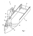
- FIG. 1 is a perspective and partially cutaway view of a flue gas cleaning device 10 is shown having a scrubber tower 20 and a ventilation device 12. For the sake of clarity, the feed area of the flue gas to be cleaned and the discharge area are not shown.
- the scrubber tower 20 has in its lower region a sump 18 in which an absorbent, in the present case seawater, is arranged. Other substances may be added to the seawater to improve the operation of the flue gas cleaning device 10.
- pumps 28 are arranged, which lead via lines 24, the absorbent to a Eindüs Scheme 26 within the scrubber tower 20.
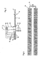
- FIG. 2 shows the flue gas cleaning device 10 according to FIG. 1 in a schematic block diagram.
- each grid 34 has a width of about 20 m and a length of about 70 m ( FIG. 3 ).
- the individual Plattenbelbyer 16 are arranged and are supplied via this with air as oxidant.
- each grid 34 has a length of about 9 m, wherein on each grid 34 Plattenbelpresenter 16 are arranged in stacked construction ( FIG. 4 ).
- Each plate aerator 16 is substantially plate-shaped and oval.
- the large half-axis of the oval extension is aligned approximately parallel to the liquid surface of the absorbent.
- the dimension of the large half-axis is about 0.7 m and the small half-axis about 0.2 m.
- the thickness of the plate aerator 16 is about 0.02 m.
- the plate aerators 16 are arranged at a distance of about 0.1 m. From a Oxidans provoke not shown is supplied via lines 30 to the grid 34 air as oxidant. This flows through the grid 34 in the plate aerator 16 and exits there through a membrane, not shown in the absorbent. As a result, a good supply of the absorbent with oxidant is achieved.
Description
- Die Erfindung betrifft eine Rauchgasreinigungsvorrichtung.
- Rauchgas, welches insbesondere bei der Verbrennung fossiler Brennstoffe entsteht, enthält unter anderem oftmals einen beachtlichen Anteil an Schwefeloxiden. Auf Grund deren Aggressivität gegenüber der Umwelt soll der Ausstoß an Schwefeloxiden so weit wie möglich vermieden werden.
- Hierzu werden Rauchgasreinigungsvorrichtungen eingesetzt.
- Vorrichtungen zur Reinigung von Rauchgas sind bereits bekannt, beispielsweise bei Kraftwerken, in denen aus fossilen Brennstoffen Energie erzeugt wird, insbesondere Kohlekraftwerke, Ölkraftwerke, Gaskraftwerke oder dergleichen. Gattungsgemäße Vorrichtungen umfassen normalerweise einen Wäscher mit Waschflüssigkeitsdüsen, die häufig in mehreren Ebenen angeordnet sind, einen Waschflüssigkeitssumpf, in dem Waschflüssigkeit gesammelt wird und einen Absorptionsbereich, der sich in einem zylindrischen Behälterabschnitt des Wäschers vom Waschflüssigkeitssumpf bis zur oberen Waschflüssigkeitsdüsenebene erstreckt. Rauchgas wird in einem unteren Abschnitt des Absorptionsbereiches in den Wäscher geleitet, strömt von dort im Wesentlichen vertikal aufwärts und verlässt den Wäscher durch eine oberhalb der Waschflüssigkeitsdüsen vorgesehene Austrittsöffnung. Die Waschflüssigkeit, auch Absorbens genannt, enthält Stoffe, die unter anderem Schwefeloxide binden beziehungsweise chemisch umwandeln. Auf seinem Weg durch den Wäscher kommt das Rauchgas mit aus den Waschflüssigkeitsdüsen austretender Waschflüssigkeit in Kontakt und wird gereinigt, insbesondere entschwefelt, was nachfolgend näher beschrieben ist. Eine derartige Reinigungsvorrichtung ist beispielsweise aus der
DE-A-10058548 bekannt. - Die Waschflüssigkeit umfasst neben Wasser vorzugsweise Stoffe mit Alkali- und/oder Erdalkalianteilen, die mit den im Rauchgas vorhandenen Schwefeloxiden und mit den im Wäscher erzeugten Schwefeloxiden reagieren. Es wird insbesondere Calciumoxid, Calciumhydroxid, Calciumhydrogencarbonat, Calciumcarbonat oder dergleichen verwendet. Bei der Verwendung von Seewasser als Waschflüssigkeit sind bereits erhebliche Mengen an alkalischen Stoffen, insbesondere Hydrogencarbonat, in der Waschflüssigkeit enthalten.
- Die alkalischen Stoffe reagieren bei Verwendung von Seewasser als Waschflüssigkeit mit den in dem Rauchgas vorhandenen Schwefeloxiden im Wesentlichen zu Sulfaten, die dann im Seewasser gelöst sind. Das Rauchgas wird auf diese Weise von den unerwünschten Schwefeloxiden gereinigt und tritt aus der Reinigungsvorrichtung aus. Die Waschflüssigkeit hingegen gelangt zusammen mit den in dieser schwebend gehaltenen Sulfatteilchen in den Waschflüssigkeitssumpf und wird dort gesammelt.
- Wird die Rauchgasreinigungsanlage mit Kalk betrieben, entsteht im Wesentlichen Calciumsulfat.
- Im Fall der Verwendung von Seewasser als Waschflüssigkeit entstehen entsprechend der gelösten alkalischen Stoffe Sulfite als unerwünschte Nebenprodukte. Bei der Rauchgasreinigungsvorrichtung gemäß
DE 295 17 698 U undEP 0756890 B1 wird das gebildete Sulfit im Absorbersumpf oxidiert. Durch Oxidationsluft soll CO2 ausgetrieben werden. Dabei soll die Menge an Waschflüssigkeit so eingestellt werden, dass im Sumpf ein pH-Wert von 3,5 bis 5 herrscht. Maßgebend ist dabei der Überschuss an Bicarbonat. Ein Meerwasserzusatzstrom kann zum Ausgleich des Bicarbonat-Bedarfs über eine Zusatzleitung in den Wäschersumpf geführt werden. Die belüftete Waschflüssigkeit wird anschließend in ein Nachreaktionsbecken geleitet und mit frischem Seewasser gemischt, das über separate Leitungen zugeführt wird. - Gattungsgemäße Rauchgasreinigungsvorrichtungen sind als Wäscher bekannt und oftmals als Wäscherturm ausgebildet. Der Wäscherturm weist in der Regel wenigstens einen unteren Einlass für das ungereinigte Rauchgas auf, unterhalb des Rauchgaseinlasses einen Sumpf für ein Absorbens, oberhalb des Rauchgaseinlasses eine Einheit, mit der das Absorbens in das eintretende Rauchgas gesprüht wird sowie einen im oberen Bereich des Wäscherturms angeordneten Auslass für das gereinigte Rauchgas. Es kommen Verfahren zum Einsatz, die als Absorbens Seewasser verwenden. Seewasser enthält neben alkalischen Stoffen insbesondere Hydrogencarbonat, welche ebenfalls mit den Schwefeloxiden reagieren.
- Bei der Verwendung von Seewasser als Absorbens fällt kein Gips an. Zu diesem Zweck wird dem verbrauchten Absorbens Sauerstoff zugeführt, so dass ein möglichst hoher Anteil an Sulfiten zu Sulfaten weiteroxidiert wird.
- Es wird eine Rauchgasreinigungsanlage mit verbesserter Verfahrenstechnik gesucht.
- Die Erfindung schlägt als Lösung eine Rauchgasreinigungsvorrichtung gemäß Anspruch 1 vor.
- Das Becken beziehungsweise ein Gefäß stehen fluidtechnisch mit dem Sumpf des Wäscherturms in Verbindung.
- Bei dem Absorbens handelt es sich um das aus der Absorptionsreaktion abgeleitete, im Wesentlichen verbrauchte fluide Absorptionsmittel, gegebenenfalls gemischt mit frischem Absorptionsmittel.
- Der Plattenbelüfter erlaubt es, das Oxidans, beispielsweise Luft, über einen vergrößerten Bereich dem Absorbens zuzuführen. Hierdurch kann eine Beschleunigung der Sulfatbildung sowie ein höherer Wirkungsgrad erreicht werden. Theoretisch können Sulfit Restwerte von < als etwas 1,5 Gew.-%, insbesondere < als etwa 1,0 Gew.-% erreicht werden. Angestrebt ist eine vollständige Oxidation. Das rückfließende Seewasser hat dann eine Qualität, die den gängigen Umweltvorschriften entspricht. Der Belüftungsbereich ist ein Teil der Belüftungsvorrichtung, in dem das Absorbens mit dem Oxidans in Kontakt gebracht werden kann.
- Der Plattenbelüfter kann beispielsweise durch Platten gebildet sein, die einen Hohlraum aufweisen, der mit einer Oxidansquelle in fluidtechnischer Verbindung steht. Die Oberfläche einer Platte des Plattenbelüfters ist mit wenigstens einer Öffnung versehen, durch die das Oxidans in das Absorbens eintreten kann. Das Oxidans ist oft gasförmig und wird durch die Öffnung in das Absorbens eingeblasen. Der Plattenbelüfter kann mehrere Platten dieser Art aufweisen, die beispielsweise gestapelt oder dergleichen angeordnet sein können. Vorzugsweise sind die Platten mit einer gemeinsamen Oxidansquelle strömungstechnisch verbunden.
- Für den Plattenbelüfter sind folgende Ausführungsformen möglich: Im Wesentlichen tellerförmig, im Wesentlichen oval, mit einer perforierten Membran, mit einer austauschbaren Membran, mit Poren für ein fluides Oxidans, wobei die Poren im Mittel einen Durchmesser von etwa 0,1 bis 1,5 mm, vorzugsweise von etwa 0,25 bis 0,9 mm, besonders bevorzugt von etwa 0,4 bis 0,8 mm aufweisen, wobei eine Häufigkeit der Poren in einem Bereich von etwa 1 bis 10 Poren pro cm2 liegen kann, die Membran kann anstelle von Poren oder zusätzlich zu Poren wenigstens einen Schlitz aufweisen, die Membran kann aus EPDM gebildet sein.
- Gemäß der Erfindung wird Seewasser als Absorbens verwendet. Dadurch können die Kosten reduziert werden. Insbesondere ist dies vorteilhaft für Anlagen, die im Bereich der Küsten installiert sind, bei denen also Seewasser kostengünstig bereitgestellt werden kann.
- Ein Belüftungsbereich wird durch ein fluidtechnisch mit einem Sumpf der Rauchgasreinigungsvorrichtung in Verbindung stehendes Belüftungsbecken gebildet. Dies erlaubt es, auch nach dem Wäscher eine Belüftungsvorrichtung separat auszubilden, so dass beide Vorrichtungen voneinander unabhängig für ihre bestimmungsgemäße Aufgabe optimal ausgebildet werden können. Es braucht beispielsweise die Belüftungsvorrichtung hinsichtlich ihrer Abmessungen nicht an die Abmessungen des Wäscherturms angepasst zu werden, dessen Abmessungen durch seinen bestimmungsgemäßen Betrieb als Wäscherturm fest vorgegeben sind. Durch die optimale Ausgestaltungsmöglichkeit des Belüftungsbeckens kann der Wirkungsgrad weiter erhöht werden. Darüber hinaus kann die Belüftungsvorrichtung nach strömungstechnischen Gesichtspunkten optimiert werden, um einen Energieaufwand für eine Strömungserzeugung zu reduzieren. Die Verbindung zwischen Sumpf und Belüftungsbecken erfolgt über einen Durchlass.
- Die Plattenbelüfter können sich im Wesentlichen über den gesamten Belüftungsbereich erstrecken. Dies erlaubt es, das Belüftungsbecken hinsichtlich seiner Abmessungen so klein wie möglich auszugestalten. Kosten können eingespart werden.
- Gemäß einer Weiterbildung weist die Belüftungsvorrichtung eine Umwälzeinheit für das Absorbens auf. Mit der Umwälzeinheit kann eine zusätzliche Erhöhung der Wirkung der Belüftungsvorrichtung erreicht werden. Durch das Umwälzen des Absorbens kann zudem eine erhöhte Oxidansmenge in das Absorbens eingeführt werden, so dass eine Beschleunigung der Reaktion erreicht werden kann. Plattenbelüfter und Umwälzeinheit können einstückig sein. So können beispielsweise an den Platten Umwälzpumpen oder dergleichen vorgesehen sein. Der Verfahrensablauf kann weiter optimiert werden. Alternativ oder zusätzlich kann eine Umwälzung auch durch eine strömungstechnische Anordnung der Plattenbelüfter, Strömungshindernisse/Einbauten und/oder Gaseinblasung erzeugt werden.
- Ferner wird vorgeschlagen, dass der Plattenbelüfter an einem Gitter angeordnet ist. Die Anordnung an einem Gitter erlaubt es, die Plattenbelüfter auf einfache Weise im Belüftungsbecken anzuordnen. Das Gitter hält die Plattenbelüfter in ihrer vorgesehenen Stellung, so dass sie ihre bestimmungsgemäße Funktion optimal wahrnehmen können. Das Gitter kann beispielsweise durch Rohrleitungen gebildet sein, durch die das Oxidans den einzelnen Platten des Plattenbelüfters zugeleitet werden kann. Auf diese Weise wird zugleich eine einfache und bequeme Speisung der Platten des Plattenbelüfters mit dem Oxidans erreicht.
- Mit der Erfindung wird ein Verfahren zum Belüften eines Absorbens möglich, wobei dem in einem Belüftungsbereich der Belüftungsvorrichtung angeordneten, flüssigen Absorbens mittels eines in dem Absorbens eingetauchten Plattenbelüfters ein gasförmiges Oxidans zugeführt wird, wobei im Absorbens das Oxidans enthaltende Gasblasen gebildet werden, deren mittlerer Durchmesser im Wesentlichen < als etwa 1,5 mm, vorzugsweise < als etwa 1,0 mm, insbesondere < als etwa 0,7 mm ist. Es hat sich gezeigt, dass die Gasblasen in Vergleich zu bekannten Belüftungsvorrichtungen länger in Kontakt mit dem Absorbens bleiben, da sie auf Grund ihrer Größe nur einer geringen Auftriebskraft im Absorbens ausgesetzt sind. Durch die Erhöhung der Anzahl der Gasblasen kann bei gleicher Oxidansmenge eine Oberflächenvergrößerung des Oxidans mit dem Absorbens erreicht werden, so dass eine Reaktion im gewünschten Sinne beschleunigt und mit einem hohen Wirkungsgrad erreicht werden kann.
- Als Oxidans kann im Wesentlichen Sauerstoff, Luft oder ein Gas oder Gasgemisch verwendet werden, das Sauerstoff enthält oder bei Einführen in das Absorbens Sauerstoff freisetzt.
- Weitere Merkmale und Vorteile können der folgenden Beschreibung eines Ausführungsbeispiels entnommen werden. Im Wesentlichen gleich bleibende Bauteile sind mit den gleichen Bezugszeichen bezeichnet. Ferner wird bezüglich gleicher Merkmale und Funktionen auf die Beschreibung zum Ausführungsbeispiel in
Figur 1 verwiesen. Die Zeichnungen sind Schemazeichnungen und dienen nur der Erläuterung des folgenden Ausführungsbeispiels. Es zeigen - Figur 1:
- Eine perspektivische Ansicht in teilweise geschnittener Darstellung einer Rauchgasreinigungsvorrichtung mit einer Belüftungsvorrichtung und einem Wäscherturm gemäß der Erfindung.
- Figur 2:
- Ausschnittweise ein Blockschaltbild für die Rauchgasreinigungsvorrichtung gemäß
Figur 1 . - Figur 3:
- Eine Draufsicht auf ein Belüftungsbecken der Belüftungsvorrichtung mit an einem Gitter angeordneten Plattenbelüftern, und
- Figur 4:
- In vergrößerter Darstellung einen Gitterausschnitt mit Plattenbelüftern.
- In
Figur 1 ist perspektivisch und teilweise als aufgeschnittene Darstellung eine Rauchgasreinigungsvorrichtung 10 dargestellt, die einen Wäscherturm 20 sowie eine Belüftungsvorrichtung 12 aufweist. Der Übersichtlichkeit halber sind der Zuführbereich des zu reinigenden Rauchgases sowie der Abführbereich nicht dargestellt. Der Wäscherturm 20 weist in seinem unteren Bereich einen Sumpf 18 auf, in dem ein Absorbens, im vorliegenden Fall Seewasser, angeordnet ist. Zum Seewasser können noch weitere Stoffe hinzugefügt sein, um die Wirkungsweise der Rauchgasreinigungsvorrichtung 10 zu verbessern. Neben dem Wäscherturm 20 strömungstechnisch in Verbindung mit dem Sumpf 18 sind Pumpen 28 angeordnet, die über Leitungen 24 das Absorbens zu einem Eindüsbereich 26 innerhalb des Wäscherturms 20 führen. Dort wird über nicht näher dargestellte Düsen das Absorbens in Gegenströmung in das dem Wäscherturm 20 von unten nach oben durchströmende Rauchgas eingedüst. Dabei werden unerwünschte chemische Bestandteile im Rauchgas ausgewaschen und/oder chemisch gebunden. Das eingedüste Absorbens sammelt sich wieder im Sumpf 18.Figur 2 zeigt die Rauchgasreinigungsvorrichtung 10 gemäßFigur 1 in schematischer Blockdarstellung. - Aus diesem Grund steht der Sumpf 18 mit einem Belüftungsbecken 14 einer Belüftungseinrichtung 12 strömungstechnisch über einen Durchlass 32 in Verbindung. Im Belüftungsbecken 14 ist ein Gitter 34 mit Plattenbelüftern 16 im Absorbens eingetaucht angeordnet. Das Belüftungsbecken 14 weist eine Breite von etwa 20 m und eine Länge von etwa 70 m auf (
Figur 3 ). Am Gitter 34 sind die einzelnen Plattenbelüfter 16 angeordnet und werden über dieses mit Luft als Oxidans versorgt. In der vorliegenden Ausgestaltung weist jedes Gitter 34 eine Länge von etwa 9 m auf, wobei an jedem Gitter 34 Plattenbelüfter 16 in Stapelbauweise angeordnet sind (Figur 4 ). Jeder Plattenbelüfter 16 ist im Wesentlichen tellerförmig und oval ausgebildet. Dabei ist die große Halbachse der ovalen Erstreckung etwa parallel zur Flüssigkeitsoberfläche des Absorbens ausgerichtet. In der vorliegenden Ausgestaltung beträgt die Abmessung der großen Halbachse etwa 0,7 m und die kleine Halbachse etwa 0,2 m. Die Dicke des Plattenbelüfters 16 liegt bei etwa 0,02 m. Am Gitter 34 sind die Plattenbelüfter 16 im Abstand von etwa 0,1 m angeordnet. Aus einer nicht näher dargestellten Oxidansquelle wird über Leitungen 30 dem Gitter 34 Luft als Oxidans zugeführt. Diese strömt über die Gitter 34 in die Plattenbelüfter 16 und tritt dort durch eine nicht näher dargestellte Membran in das Absorbens aus. Hierdurch wird eine gute Versorgung des Absorbens mit Oxidans erreicht. - Das in den Figuren dargestellte Ausführungsbeispiel dient lediglich der Erläuterung der Erfindung und ist für diese nicht beschränkend.
Claims (8)
- Rauchgasreinigungsvorrichtung mit einem Wäscherturm (20), der mindestens einen unteren Einlass für ungereinigtes Rauchgas aufweist, ferner unterhalb des Rauchgaseinlasses einen Sumpf (18) für ein Seewasser-Absorbens und oberhalb des Rauchgaseinlasses eine Einheit, mit der das Absorbens in das eintretende Rauchgas gespritzt wird, sowie einen im oberen Bereich des Wäscherturms (20) angeordneten Auslass für gereinigtes Abgas, gekennzeichnet durch folgende Merkmale:a) neben dem Wäscherturm (20) sind Pumpen (28) strömungstechnisch in Verbindung mit dem Sumpf (18) angeordnet, so dass Seewasser-Absorbens über eine Wand durch einen Durchlass in den Sumpf (18) fließen kann, wobei die Pumpen (28), über Leistungen (24) das Seewasser-Absorbens zu einem Eindüsbereich (26) innerhalb des Wäscherturms (20) führen,b) der Sumpf (18) steht fluidtechnisch mit einem BelüftungsBecken (14) in Verbindung, welches einen Belüftungsbereich einer Belüftungsvorrichtung (12) bildet,c) der Belüftungsbereich weist mindestens einen Plattenbelüfter (16) auf, der in das im Belüftungsbereich angeordnete Seewasser-Absorbens eingetaucht ist.
- Rauchgasreinigungsvorrichtung nach Anspruch 1, bei der der Sumpf (18) und das Becken (14) durch eine Öffnung strömungstechnisch in Verbindung stehen.
- Rauchgasreinigungsvorrichtung nach Anspruch 1, bei der der Sumpf (18) und das Becken (14) über einen Durchlass (32) strömungstechnisch in Verbindung stehen.
- Rauchgasreinigungsvorrichtung nach Anspruch 1, bei der der Sumpf (18) und das Becken (14) durch eine Rohrleitung strömungstechnisch in Verbindung stehen.
- Rauchgasreinigungsvorrichtung nach Anspruch 1, bei der der Sumpf (18) und das Becken (14) ein gemeinsames Becken bilden.
- Rauchgasreinigungsvorrichtung nach Anspruch 1, bei der ein Belüftungsbereich des Beckens (14) außerhalb eines Bereichs angeordnet ist, der den Sumpf (18) bildet.
- Rauchgasreinigungsvorrichtung nach Anspruch 1, bei der die Belüftungsvorrichtung (12) eine Umwälzeinheit für das Absorbens aufweist.
- Rauchgasreinigungsvorrichtung nach Anspruch 1, bei der das Seewasser-Absorbens ein verbrauchtes Seewasser-Absorptionsmittel, gemischt mit frischem Absorptionsmittel, ist.
Priority Applications (1)
| Application Number | Priority Date | Filing Date | Title |
|---|---|---|---|
| DK09008295T DK2100657T3 (da) | 2006-12-23 | 2006-12-23 | Røggasrensningsenhed |
Applications Claiming Priority (2)
| Application Number | Priority Date | Filing Date | Title |
|---|---|---|---|
| PCT/EP2006/012527 WO2008077430A1 (de) | 2006-12-23 | 2006-12-23 | Belüftungsvorrichtung für eine rauchgasreinigungsvorrichtung |
| EP06841162A EP1960088A1 (de) | 2006-12-23 | 2006-12-23 | Belüftungsvorrichtung für eine rauchgasreinigungsvorrichtung |
Related Parent Applications (2)
| Application Number | Title | Priority Date | Filing Date |
|---|---|---|---|
| EP06841162.8 Division | 2006-12-23 | ||
| EP06841162A Division EP1960088A1 (de) | 2006-12-23 | 2006-12-23 | Belüftungsvorrichtung für eine rauchgasreinigungsvorrichtung |
Publications (2)
| Publication Number | Publication Date |
|---|---|
| EP2100657A1 EP2100657A1 (de) | 2009-09-16 |
| EP2100657B1 true EP2100657B1 (de) | 2013-01-23 |
Family
ID=38372457
Family Applications (2)
| Application Number | Title | Priority Date | Filing Date |
|---|---|---|---|
| EP06841162A Withdrawn EP1960088A1 (de) | 2006-12-23 | 2006-12-23 | Belüftungsvorrichtung für eine rauchgasreinigungsvorrichtung |
| EP09008295A Active EP2100657B1 (de) | 2006-12-23 | 2006-12-23 | Rauchgasreinigungsvorrichtung |
Family Applications Before (1)
| Application Number | Title | Priority Date | Filing Date |
|---|---|---|---|
| EP06841162A Withdrawn EP1960088A1 (de) | 2006-12-23 | 2006-12-23 | Belüftungsvorrichtung für eine rauchgasreinigungsvorrichtung |
Country Status (8)
| Country | Link |
|---|---|
| EP (2) | EP1960088A1 (de) |
| JP (1) | JP2008155195A (de) |
| KR (3) | KR20090087029A (de) |
| CN (1) | CN101300061A (de) |
| BR (1) | BRPI0622233A2 (de) |
| ES (1) | ES2400262T3 (de) |
| PT (1) | PT2100657E (de) |
| WO (1) | WO2008077430A1 (de) |
Cited By (1)
| Publication number | Priority date | Publication date | Assignee | Title |
|---|---|---|---|---|
| EP3293153A1 (de) | 2016-09-09 | 2018-03-14 | Doosan Lentjes GmbH | A seawater aeration system |
Families Citing this family (2)
| Publication number | Priority date | Publication date | Assignee | Title |
|---|---|---|---|---|
| JP5754877B2 (ja) | 2009-03-31 | 2015-07-29 | 三菱日立パワーシステムズ株式会社 | 酸化槽、海水処理装置及び海水脱硫システム |
| DE102009052670B4 (de) * | 2009-11-12 | 2017-10-05 | Sartorius Stedim Biotech Gmbh | Begasungsvorrichtung für Bioreaktoren |
Family Cites Families (16)
| Publication number | Priority date | Publication date | Assignee | Title |
|---|---|---|---|---|
| US4495163A (en) * | 1982-02-25 | 1985-01-22 | Domtar Inc. | Fluidized bed sulfur dioxide removal |
| DE3227187C1 (de) * | 1982-07-21 | 1988-12-01 | Gottfried Bischoff Bau kompl. Gasreinigungs- und Wasserrückkühlanlagen GmbH & Co KG, 4300 Essen | Waschturm fuer eine Anlage zur Entschwefelung von Rauchgas |
| CN1075743C (zh) | 1994-05-11 | 2001-12-05 | 巴布考克日立株式会社 | 采用固体脱硫剂的湿式烟道气脱硫设备和方法 |
| US5494614A (en) | 1994-05-23 | 1996-02-27 | The Babcock & Wilcox Company | Wet flue gas desulfurization scrubber in situ forced oxidation retrofit |
| DE19527836A1 (de) * | 1995-07-29 | 1997-01-30 | Gottfried Bischoff Gmbh & Co | Verfahren zum Abtrennen von Schwefeldioxid aus Abgas |
| DE29517697U1 (de) | 1995-07-29 | 1996-01-18 | Gottfried Bischoff Gmbh & Co | Rauchgasentschwefelungsanlage |
| JPH09239233A (ja) * | 1996-03-05 | 1997-09-16 | Mitsubishi Heavy Ind Ltd | 排煙脱硫方法及び装置並びに該装置を搭載した船舶 |
| US5928615A (en) | 1996-07-12 | 1999-07-27 | Mcdermott Technology, Inc. | Wet scrubber oxidation air sparger arrangement |
| JP2001129352A (ja) | 1999-11-02 | 2001-05-15 | Fujikasui Engineering Co Ltd | 海水による排ガス脱硫高度処理プロセス |
| DE10058548C1 (de) | 2000-11-24 | 2001-10-25 | Lurgi Lentjes Bischoff Gmbh | Waschturm für eine Anlage zur Entschwefelung von Rauchgas |
| US20020070164A1 (en) | 2000-12-11 | 2002-06-13 | Huber & Suhner Ag | Aeration device for water and a method for aerating water |
| US6543753B1 (en) | 2001-10-12 | 2003-04-08 | Environmental Dynamics, Inc. | Air diffuser membrane treated with biocide |
| US7044453B2 (en) | 2004-01-08 | 2006-05-16 | Environmental Dynamics, Inc. | Membrane diffuser with uniform gas distribution |
| JP4460975B2 (ja) | 2004-08-20 | 2010-05-12 | 三菱重工業株式会社 | 海水処理方法および海水処理装置 |
| EP1707874A1 (de) * | 2005-03-18 | 2006-10-04 | Lurgi Lentjes AG | Rauchgasreinigungsvorrichtung |
| EP1707875A1 (de) * | 2005-03-18 | 2006-10-04 | Lurgi Lentjes AG | Rauchgasreinigungsvorrichtung mit verbesserter Oxidationseinrichtung im Waschflüssigkeitssumpf |
-
2006
- 2006-12-23 PT PT90082959T patent/PT2100657E/pt unknown
- 2006-12-23 BR BRPI0622233-1A patent/BRPI0622233A2/pt not_active Application Discontinuation
- 2006-12-23 KR KR1020097011425A patent/KR20090087029A/ko not_active IP Right Cessation
- 2006-12-23 WO PCT/EP2006/012527 patent/WO2008077430A1/de active Application Filing
- 2006-12-23 KR KR1020137020277A patent/KR101398118B1/ko active IP Right Grant
- 2006-12-23 EP EP06841162A patent/EP1960088A1/de not_active Withdrawn
- 2006-12-23 KR KR1020127006840A patent/KR20120061888A/ko active Application Filing
- 2006-12-23 ES ES09008295T patent/ES2400262T3/es active Active
- 2006-12-23 EP EP09008295A patent/EP2100657B1/de active Active
- 2006-12-23 CN CNA2006800011974A patent/CN101300061A/zh active Pending
-
2007
- 2007-07-12 JP JP2007183026A patent/JP2008155195A/ja active Pending
Cited By (3)
| Publication number | Priority date | Publication date | Assignee | Title |
|---|---|---|---|---|
| EP3293153A1 (de) | 2016-09-09 | 2018-03-14 | Doosan Lentjes GmbH | A seawater aeration system |
| WO2018046184A1 (en) | 2016-09-09 | 2018-03-15 | Doosan Lentjes Gmbh | A seawater aeration system |
| US10919004B2 (en) | 2016-09-09 | 2021-02-16 | Doosan Lentjes Gmbh | Seawater aeration system |
Also Published As
| Publication number | Publication date |
|---|---|
| JP2008155195A (ja) | 2008-07-10 |
| EP1960088A1 (de) | 2008-08-27 |
| EP2100657A1 (de) | 2009-09-16 |
| WO2008077430A1 (de) | 2008-07-03 |
| CN101300061A (zh) | 2008-11-05 |
| ES2400262T3 (es) | 2013-04-08 |
| KR20130096327A (ko) | 2013-08-29 |
| KR20120061888A (ko) | 2012-06-13 |
| BRPI0622233A2 (pt) | 2012-01-03 |
| KR101398118B1 (ko) | 2014-05-28 |
| KR20090087029A (ko) | 2009-08-14 |
| PT2100657E (pt) | 2013-02-26 |
Similar Documents
| Publication | Publication Date | Title |
|---|---|---|
| DE2708497C3 (de) | Verfahren und Vorrichtung zur Entfernung von Verunreinigungen aus einem Abgas | |
| DE102007050904B4 (de) | Anlage und Verfahren zur Reinigung von Rauchgasen | |
| DE112007003270B4 (de) | Entschwefelungsanlage für nasses Rauchgas | |
| DE2532373C3 (de) | Verfahren und Vorrichtung zum Reinigen von Rauchgasen und anderen Abgasen, die Schwefeldioxyd enthalten | |
| DE112006003662T5 (de) | Feuchtrauchgas-Entschwefelungsgerät | |
| DE69828815T2 (de) | Gas-flüssigkeit-kontaktapparat mit einer flüssigkeits-wiederverteilungsvorrichtung | |
| DE102010019510B4 (de) | Verfahren zum Einbringen chemischer Zusätze in Gewässer | |
| DE2133481A1 (de) | Verfahren und einrichtung zur schutzgasreinigung fuer rohoeltanks von schiffen | |
| DE19516660C2 (de) | Verfahren und Einrichtung mit gasbeschichteter Siebplatte zur nassen Entschwefelung von Rauchgas | |
| DE112011101262B4 (de) | Nass-Rauchgasentschwefelungs-Einrichtung | |
| EP0229587B1 (de) | Verfahren zum Entschwefeln von schwefelwasserstoffhaltigem Gas und Vorrichtung zur Durchführung des Verfahrens | |
| EP2687281B1 (de) | Anlage und Verfahren zur Absorption von Einzelkomponenten in Gasen | |
| EP1970116B1 (de) | Anlage und Verfahren zur Rauchgasreinigung | |
| DE3329633A1 (de) | Verfahren und waschturm zur entschwefelung von industriellen rauchgasen | |
| EP2100657B1 (de) | Rauchgasreinigungsvorrichtung | |
| DE3410109C3 (de) | Vorrichtung zur nassen Entschwefelung von Rauchgasen | |
| DE2847047A1 (de) | Verfahren zur entschwefelung schwefelhaltiger prozessgase | |
| CH617867A5 (de) | ||
| EP1682249A1 (de) | Verfahren und anlage zur gasreinigung | |
| EP1707875A1 (de) | Rauchgasreinigungsvorrichtung mit verbesserter Oxidationseinrichtung im Waschflüssigkeitssumpf | |
| WO2016141988A1 (de) | Rauchgasreinigungsanlage und verfahren zur reinigung von rauchgas | |
| DE10222915A1 (de) | Verfahren und Vorrichtung zur erneuten Aktivierung wabenförmig aufgebauter Katalysatorelemente für die Entstickung von Rauchgasen | |
| EP1707874A1 (de) | Rauchgasreinigungsvorrichtung | |
| EP1707877A1 (de) | Rauchgasreinigungsvorrichtung mit geteiltem Waschflüssigkeitssumpf | |
| DE19753227A1 (de) | Absorberturm |
Legal Events
| Date | Code | Title | Description |
|---|---|---|---|
| PUAI | Public reference made under article 153(3) epc to a published international application that has entered the european phase |
Free format text: ORIGINAL CODE: 0009012 |
|
| AC | Divisional application: reference to earlier application |
Ref document number: 1960088 Country of ref document: EP Kind code of ref document: P |
|
| AK | Designated contracting states |
Kind code of ref document: A1 Designated state(s): AT BE BG CH CY CZ DE DK EE ES FI FR GB GR HU IE IS IT LI LT LU LV MC NL PL PT RO SE SI SK TR |
|
| RIN1 | Information on inventor provided before grant (corrected) |
Inventor name: PELKMAN, AAT Inventor name: WEITEMEIER, MARTIN Inventor name: DELLE, FRANK Inventor name: ZIEMANN-NOETHE, ANNETTE Inventor name: OBERHEID, FRANK |
|
| 17P | Request for examination filed |
Effective date: 20100310 |
|
| 17Q | First examination report despatched |
Effective date: 20100409 |
|
| RAP1 | Party data changed (applicant data changed or rights of an application transferred) |
Owner name: DOOSAN LENTJES GMBH |
|
| GRAP | Despatch of communication of intention to grant a patent |
Free format text: ORIGINAL CODE: EPIDOSNIGR1 |
|
| GRAS | Grant fee paid |
Free format text: ORIGINAL CODE: EPIDOSNIGR3 |
|
| GRAA | (expected) grant |
Free format text: ORIGINAL CODE: 0009210 |
|
| AC | Divisional application: reference to earlier application |
Ref document number: 1960088 Country of ref document: EP Kind code of ref document: P |
|
| AK | Designated contracting states |
Kind code of ref document: B1 Designated state(s): AT BE BG CH CY CZ DE DK EE ES FI FR GB GR HU IE IS IT LI LT LU LV MC NL PL PT RO SE SI SK TR |
|
| REG | Reference to a national code |
Ref country code: GB Ref legal event code: FG4D Free format text: NOT ENGLISH |
|
| REG | Reference to a national code |
Ref country code: CH Ref legal event code: EP |
|
| REG | Reference to a national code |
Ref country code: DK Ref legal event code: T3 |
|
| REG | Reference to a national code |
Ref country code: AT Ref legal event code: REF Ref document number: 594645 Country of ref document: AT Kind code of ref document: T Effective date: 20130215 Ref country code: CH Ref legal event code: EP |
|
| REG | Reference to a national code |
Ref country code: SE Ref legal event code: TRGR Ref country code: PT Ref legal event code: SC4A Free format text: AVAILABILITY OF NATIONAL TRANSLATION Effective date: 20130218 |
|
| REG | Reference to a national code |
Ref country code: IE Ref legal event code: FG4D Free format text: LANGUAGE OF EP DOCUMENT: GERMAN |
|
| REG | Reference to a national code |
Ref country code: DE Ref legal event code: R096 Ref document number: 502006012465 Country of ref document: DE Effective date: 20130321 |
|
| REG | Reference to a national code |
Ref country code: NL Ref legal event code: T3 |
|
| REG | Reference to a national code |
Ref country code: ES Ref legal event code: FG2A Ref document number: 2400262 Country of ref document: ES Kind code of ref document: T3 Effective date: 20130408 |
|
| REG | Reference to a national code |
Ref country code: GR Ref legal event code: EP Ref document number: 20130400535 Country of ref document: GR Effective date: 20130418 |
|
| REG | Reference to a national code |
Ref country code: LT Ref legal event code: MG4D |
|
| PG25 | Lapsed in a contracting state [announced via postgrant information from national office to epo] |
Ref country code: LT Free format text: LAPSE BECAUSE OF FAILURE TO SUBMIT A TRANSLATION OF THE DESCRIPTION OR TO PAY THE FEE WITHIN THE PRESCRIBED TIME-LIMIT Effective date: 20130123 Ref country code: BG Free format text: LAPSE BECAUSE OF FAILURE TO SUBMIT A TRANSLATION OF THE DESCRIPTION OR TO PAY THE FEE WITHIN THE PRESCRIBED TIME-LIMIT Effective date: 20130423 |
|
| PG25 | Lapsed in a contracting state [announced via postgrant information from national office to epo] |
Ref country code: LV Free format text: LAPSE BECAUSE OF FAILURE TO SUBMIT A TRANSLATION OF THE DESCRIPTION OR TO PAY THE FEE WITHIN THE PRESCRIBED TIME-LIMIT Effective date: 20130123 Ref country code: SI Free format text: LAPSE BECAUSE OF FAILURE TO SUBMIT A TRANSLATION OF THE DESCRIPTION OR TO PAY THE FEE WITHIN THE PRESCRIBED TIME-LIMIT Effective date: 20130123 Ref country code: PL Free format text: LAPSE BECAUSE OF FAILURE TO SUBMIT A TRANSLATION OF THE DESCRIPTION OR TO PAY THE FEE WITHIN THE PRESCRIBED TIME-LIMIT Effective date: 20130123 |
|
| PG25 | Lapsed in a contracting state [announced via postgrant information from national office to epo] |
Ref country code: RO Free format text: LAPSE BECAUSE OF FAILURE TO SUBMIT A TRANSLATION OF THE DESCRIPTION OR TO PAY THE FEE WITHIN THE PRESCRIBED TIME-LIMIT Effective date: 20130123 Ref country code: SK Free format text: LAPSE BECAUSE OF FAILURE TO SUBMIT A TRANSLATION OF THE DESCRIPTION OR TO PAY THE FEE WITHIN THE PRESCRIBED TIME-LIMIT Effective date: 20130123 Ref country code: CZ Free format text: LAPSE BECAUSE OF FAILURE TO SUBMIT A TRANSLATION OF THE DESCRIPTION OR TO PAY THE FEE WITHIN THE PRESCRIBED TIME-LIMIT Effective date: 20130123 Ref country code: EE Free format text: LAPSE BECAUSE OF FAILURE TO SUBMIT A TRANSLATION OF THE DESCRIPTION OR TO PAY THE FEE WITHIN THE PRESCRIBED TIME-LIMIT Effective date: 20130123 |
|
| PG25 | Lapsed in a contracting state [announced via postgrant information from national office to epo] |
Ref country code: CY Free format text: LAPSE BECAUSE OF FAILURE TO SUBMIT A TRANSLATION OF THE DESCRIPTION OR TO PAY THE FEE WITHIN THE PRESCRIBED TIME-LIMIT Effective date: 20130123 |
|
| PLBE | No opposition filed within time limit |
Free format text: ORIGINAL CODE: 0009261 |
|
| STAA | Information on the status of an ep patent application or granted ep patent |
Free format text: STATUS: NO OPPOSITION FILED WITHIN TIME LIMIT |
|
| 26N | No opposition filed |
Effective date: 20131024 |
|
| REG | Reference to a national code |
Ref country code: DE Ref legal event code: R097 Ref document number: 502006012465 Country of ref document: DE Effective date: 20131024 |
|
| REG | Reference to a national code |
Ref country code: CH Ref legal event code: PL |
|
| PG25 | Lapsed in a contracting state [announced via postgrant information from national office to epo] |
Ref country code: MC Free format text: LAPSE BECAUSE OF FAILURE TO SUBMIT A TRANSLATION OF THE DESCRIPTION OR TO PAY THE FEE WITHIN THE PRESCRIBED TIME-LIMIT Effective date: 20130123 Ref country code: LU Free format text: LAPSE BECAUSE OF FAILURE TO SUBMIT A TRANSLATION OF THE DESCRIPTION OR TO PAY THE FEE WITHIN THE PRESCRIBED TIME-LIMIT Effective date: 20131223 |
|
| PG25 | Lapsed in a contracting state [announced via postgrant information from national office to epo] |
Ref country code: LI Free format text: LAPSE BECAUSE OF NON-PAYMENT OF DUE FEES Effective date: 20131231 Ref country code: CH Free format text: LAPSE BECAUSE OF NON-PAYMENT OF DUE FEES Effective date: 20131231 |
|
| PG25 | Lapsed in a contracting state [announced via postgrant information from national office to epo] |
Ref country code: HU Free format text: LAPSE BECAUSE OF FAILURE TO SUBMIT A TRANSLATION OF THE DESCRIPTION OR TO PAY THE FEE WITHIN THE PRESCRIBED TIME-LIMIT; INVALID AB INITIO Effective date: 20061223 |
|
| REG | Reference to a national code |
Ref country code: FR Ref legal event code: PLFP Year of fee payment: 10 |
|
| REG | Reference to a national code |
Ref country code: FR Ref legal event code: PLFP Year of fee payment: 11 |
|
| PGFP | Annual fee paid to national office [announced via postgrant information from national office to epo] |
Ref country code: TR Payment date: 20151223 Year of fee payment: 10 |
|
| REG | Reference to a national code |
Ref country code: FR Ref legal event code: PLFP Year of fee payment: 12 |
|
| PGFP | Annual fee paid to national office [announced via postgrant information from national office to epo] |
Ref country code: PT Payment date: 20191217 Year of fee payment: 14 Ref country code: IE Payment date: 20191217 Year of fee payment: 14 Ref country code: FI Payment date: 20191217 Year of fee payment: 14 Ref country code: NL Payment date: 20191217 Year of fee payment: 14 |
|
| PGFP | Annual fee paid to national office [announced via postgrant information from national office to epo] |
Ref country code: DK Payment date: 20191217 Year of fee payment: 14 Ref country code: IT Payment date: 20191216 Year of fee payment: 14 Ref country code: BE Payment date: 20191217 Year of fee payment: 14 Ref country code: GR Payment date: 20191213 Year of fee payment: 14 Ref country code: IS Payment date: 20191213 Year of fee payment: 14 |
|
| PGFP | Annual fee paid to national office [announced via postgrant information from national office to epo] |
Ref country code: ES Payment date: 20200122 Year of fee payment: 14 Ref country code: GB Payment date: 20191220 Year of fee payment: 14 |
|
| REG | Reference to a national code |
Ref country code: FI Ref legal event code: MAE |
|
| REG | Reference to a national code |
Ref country code: DK Ref legal event code: EBP Effective date: 20201231 |
|
| PG25 | Lapsed in a contracting state [announced via postgrant information from national office to epo] |
Ref country code: PT Free format text: LAPSE BECAUSE OF NON-PAYMENT OF DUE FEES Effective date: 20210623 Ref country code: FI Free format text: LAPSE BECAUSE OF NON-PAYMENT OF DUE FEES Effective date: 20201223 |
|
| REG | Reference to a national code |
Ref country code: NL Ref legal event code: MM Effective date: 20210101 |
|
| GBPC | Gb: european patent ceased through non-payment of renewal fee |
Effective date: 20201223 |
|
| REG | Reference to a national code |
Ref country code: BE Ref legal event code: MM Effective date: 20201231 |
|
| PG25 | Lapsed in a contracting state [announced via postgrant information from national office to epo] |
Ref country code: NL Free format text: LAPSE BECAUSE OF NON-PAYMENT OF DUE FEES Effective date: 20210101 |
|
| PG25 | Lapsed in a contracting state [announced via postgrant information from national office to epo] |
Ref country code: IE Free format text: LAPSE BECAUSE OF NON-PAYMENT OF DUE FEES Effective date: 20201223 Ref country code: IT Free format text: LAPSE BECAUSE OF NON-PAYMENT OF DUE FEES Effective date: 20201223 |
|
| PG25 | Lapsed in a contracting state [announced via postgrant information from national office to epo] |
Ref country code: GB Free format text: LAPSE BECAUSE OF NON-PAYMENT OF DUE FEES Effective date: 20201223 Ref country code: GR Free format text: LAPSE BECAUSE OF NON-PAYMENT OF DUE FEES Effective date: 20210707 |
|
| PG25 | Lapsed in a contracting state [announced via postgrant information from national office to epo] |
Ref country code: DK Free format text: LAPSE BECAUSE OF NON-PAYMENT OF DUE FEES Effective date: 20201231 |
|
| PGFP | Annual fee paid to national office [announced via postgrant information from national office to epo] |
Ref country code: FR Payment date: 20211220 Year of fee payment: 16 Ref country code: SE Payment date: 20211220 Year of fee payment: 16 Ref country code: AT Payment date: 20211216 Year of fee payment: 16 Ref country code: DE Payment date: 20211115 Year of fee payment: 16 |
|
| REG | Reference to a national code |
Ref country code: ES Ref legal event code: FD2A Effective date: 20220222 |
|
| PG25 | Lapsed in a contracting state [announced via postgrant information from national office to epo] |
Ref country code: ES Free format text: LAPSE BECAUSE OF NON-PAYMENT OF DUE FEES Effective date: 20201224 |
|
| PG25 | Lapsed in a contracting state [announced via postgrant information from national office to epo] |
Ref country code: TR Free format text: LAPSE BECAUSE OF NON-PAYMENT OF DUE FEES Effective date: 20201223 |
|
| PG25 | Lapsed in a contracting state [announced via postgrant information from national office to epo] |
Ref country code: BE Free format text: LAPSE BECAUSE OF NON-PAYMENT OF DUE FEES Effective date: 20201231 |
|
| REG | Reference to a national code |
Ref country code: DE Ref legal event code: R119 Ref document number: 502006012465 Country of ref document: DE |
|
| REG | Reference to a national code |
Ref country code: SE Ref legal event code: EUG |
|
| REG | Reference to a national code |
Ref country code: AT Ref legal event code: MM01 Ref document number: 594645 Country of ref document: AT Kind code of ref document: T Effective date: 20221223 |
|
| PG25 | Lapsed in a contracting state [announced via postgrant information from national office to epo] |
Ref country code: SE Free format text: LAPSE BECAUSE OF NON-PAYMENT OF DUE FEES Effective date: 20221224 Ref country code: DE Free format text: LAPSE BECAUSE OF NON-PAYMENT OF DUE FEES Effective date: 20230701 Ref country code: AT Free format text: LAPSE BECAUSE OF NON-PAYMENT OF DUE FEES Effective date: 20221223 |
|
| PG25 | Lapsed in a contracting state [announced via postgrant information from national office to epo] |
Ref country code: FR Free format text: LAPSE BECAUSE OF NON-PAYMENT OF DUE FEES Effective date: 20221231 |