EP3293084A1 - Lateral energy absorption system - Google Patents
Lateral energy absorption system Download PDFInfo
- Publication number
- EP3293084A1 EP3293084A1 EP17189833.1A EP17189833A EP3293084A1 EP 3293084 A1 EP3293084 A1 EP 3293084A1 EP 17189833 A EP17189833 A EP 17189833A EP 3293084 A1 EP3293084 A1 EP 3293084A1
- Authority
- EP
- European Patent Office
- Prior art keywords
- carbon structure
- vehicle
- tubes
- carbon
- side beam
- Prior art date
- Legal status (The legal status is an assumption and is not a legal conclusion. Google has not performed a legal analysis and makes no representation as to the accuracy of the status listed.)
- Withdrawn
Links
Images


Classifications
-
- B—PERFORMING OPERATIONS; TRANSPORTING
- B62—LAND VEHICLES FOR TRAVELLING OTHERWISE THAN ON RAILS
- B62D—MOTOR VEHICLES; TRAILERS
- B62D21/00—Understructures, i.e. chassis frame on which a vehicle body may be mounted
- B62D21/15—Understructures, i.e. chassis frame on which a vehicle body may be mounted having impact absorbing means, e.g. a frame designed to permanently or temporarily change shape or dimension upon impact with another body
- B62D21/157—Understructures, i.e. chassis frame on which a vehicle body may be mounted having impact absorbing means, e.g. a frame designed to permanently or temporarily change shape or dimension upon impact with another body for side impacts
-
- B—PERFORMING OPERATIONS; TRANSPORTING
- B60—VEHICLES IN GENERAL
- B60J—WINDOWS, WINDSCREENS, NON-FIXED ROOFS, DOORS, OR SIMILAR DEVICES FOR VEHICLES; REMOVABLE EXTERNAL PROTECTIVE COVERINGS SPECIALLY ADAPTED FOR VEHICLES
- B60J5/00—Doors
- B60J5/04—Doors arranged at the vehicle sides
- B60J5/042—Reinforcement elements
- B60J5/0422—Elongated type elements, e.g. beams, cables, belts or wires
- B60J5/0438—Elongated type elements, e.g. beams, cables, belts or wires characterised by the type of elongated elements
- B60J5/0443—Beams
- B60J5/0444—Beams characterised by a special cross section
-
- B—PERFORMING OPERATIONS; TRANSPORTING
- B60—VEHICLES IN GENERAL
- B60J—WINDOWS, WINDSCREENS, NON-FIXED ROOFS, DOORS, OR SIMILAR DEVICES FOR VEHICLES; REMOVABLE EXTERNAL PROTECTIVE COVERINGS SPECIALLY ADAPTED FOR VEHICLES
- B60J5/00—Doors
- B60J5/04—Doors arranged at the vehicle sides
- B60J5/042—Reinforcement elements
- B60J5/0456—Behaviour during impact
- B60J5/0461—Behaviour during impact characterised by a pre-defined mode of deformation or displacement in order to absorb impact
-
- B—PERFORMING OPERATIONS; TRANSPORTING
- B62—LAND VEHICLES FOR TRAVELLING OTHERWISE THAN ON RAILS
- B62D—MOTOR VEHICLES; TRAILERS
- B62D25/00—Superstructure or monocoque structure sub-units; Parts or details thereof not otherwise provided for
- B62D25/02—Side panels
- B62D25/025—Side sills thereof
-
- B—PERFORMING OPERATIONS; TRANSPORTING
- B62—LAND VEHICLES FOR TRAVELLING OTHERWISE THAN ON RAILS
- B62D—MOTOR VEHICLES; TRAILERS
- B62D25/00—Superstructure or monocoque structure sub-units; Parts or details thereof not otherwise provided for
- B62D25/20—Floors or bottom sub-units
- B62D25/2009—Floors or bottom sub-units in connection with other superstructure subunits
- B62D25/2036—Floors or bottom sub-units in connection with other superstructure subunits the subunits being side panels, sills or pillars
-
- B—PERFORMING OPERATIONS; TRANSPORTING
- B62—LAND VEHICLES FOR TRAVELLING OTHERWISE THAN ON RAILS
- B62D—MOTOR VEHICLES; TRAILERS
- B62D29/00—Superstructures, understructures, or sub-units thereof, characterised by the material thereof
- B62D29/001—Superstructures, understructures, or sub-units thereof, characterised by the material thereof characterised by combining metal and synthetic material
-
- B—PERFORMING OPERATIONS; TRANSPORTING
- B62—LAND VEHICLES FOR TRAVELLING OTHERWISE THAN ON RAILS
- B62D—MOTOR VEHICLES; TRAILERS
- B62D29/00—Superstructures, understructures, or sub-units thereof, characterised by the material thereof
- B62D29/04—Superstructures, understructures, or sub-units thereof, characterised by the material thereof predominantly of synthetic material
Definitions
- the disclosure generally relates to an energy absorption system for a vehicle.
- Typical passenger vehicles e.g., cars, trucks
- commercial vehicles e.g., buses, semi-trucks
- these vehicles incorporate a variety of safety features including seatbelts, airbags, anti-lock brakes, etc.
- Many if not all of these safety features are on electric vehicles as well, but electric vehicles are not powered in the same way that traditional vehicles are.
- electric vehicles operate using electric power stored in one or more batteries on the electric vehicle. During operation, the stored electrical energy is controllably released to drive an electric motor. The electric motor converts the electrical energy into mechanical energy, which propels the vehicle. Accordingly, the electric vehicle protects the battery as well as the vehicle occupants in a collision.
- the embodiments discussed below include a vehicle with a lateral energy absorption system.
- the lateral energy absorption system may include side beams and lightweight energy absorbing carbon structures.
- the carbon structures may be placed within the side beams.
- the side beams and/or carbon structures may be arranged and/or include various features that enable progressive energy absorption during an impact (e.g., a crumple zone).
- the carbon structure may include carbon tubes coupled together with flanges. These carbon tubes and flanges may be made out of carbon sheets laid on top of one another in a resin that binds the carbon sheets together into a composite material that is lightweight and capable of absorbing significant amounts of energy.
- FIG. 1 is a perspective view of an embodiment of a vehicle 10 with a lateral energy absorption system 12.
- the lateral energy absorption system 12 is designed to absorb a side impact on the vehicle 10.
- development vehicles are put through small overlap tests that measure a vehicle's ability to absorb a side impact when a small portion of the car's structure impacts an object such as a pole 14 or tree.
- These kinds of tests and their real life counterpart crashes can be demanding on, for example, vehicle 10 because the sides 16 of the vehicle 10 are thin compared to other portions of the vehicle 10 (e.g., front) and therefore a significant amount of energy needs to be absorbed in a small space to block or reduce injury to vehicle occupants, and in the case of an electric vehicle protection of the battery.
- the term electric vehicle does not limit the applicability of the lateral energy absorption system 12. Indeed, the lateral energy absorption system 12 may be applicable to non-electric vehicles or hybrids as well. Furthermore, the term electric vehicle or vehicle is understood to include a variety of electric or non-electric vehicles (e.g., trucks, cars, buses).
- the lateral energy absorption system 12 includes one or more side beams 20 position at or near a bottom 22 of the vehicle sides 16. These side beams 20 may be referred to colloquially as the "sill” or “pontoons.”
- the one or more of the side beams 20 may couple to crossbeams 24 that extend through the vehicle 10 and couple to one or more opposing side beams 20 on the opposite side 16 of the vehicle 10.
- the side beams 20 may be made out of aluminum and/or steel.
- one of the side beams 20 may be made out of steel and the other out of aluminum. In another embodiment, both side beams 20 may be made out of steel or aluminum.
- each of the side beams 20 may receive one or more carbon structures 26.
- the carbon structures 26 may extend along an entire length of the side beams 20 from a first end 28, proximate a front end of the vehicle 10, to a second end 30 proximate a rear end of the vehicle 10.
- the carbon structures 26 may extend over a portion of the side beams 20 (e.g., 10%, 25%, 25%, 50% of the side beam length).
- the carbon structures 26 may positioned in the side beams 20 at points where stress concentrations may be maximized during an impact (e.g., center of the side beams 20).
- the carbon structures 26 may also be placed where an impact could cause the greatest amount of damage to a passenger and/or battery (e.g., along the side of the car seat). As will be explained in detail below, the carbon structures 26 cushion impacts by absorbing energy similar to a crumple zone designed into the front of some vehicles. In other words, the carbon structures 26 absorb energy through controlled deformation during an impact. These carbon structures 26 may therefore better protect the vehicle occupants by reducing acceleration and/or deceleration of the vehicle occupants as well as blocking or reducing penetration of the vehicle 10 during a collision.
- FIG. 2 is a perspective view of an embodiment of a vehicle 10 with a lateral energy absorption system 12.
- the lateral energy absorption system 12 includes side beams 20 (e.g., upper side beam 32, lower side beam 34) that house one or more energy absorbing carbon structures 26 (e.g., upper carbon structure 36, lower carbon structure 38).
- the carbon structure 26 may include one or more tubes 40 coupled together with one or more carbon flanges 42.
- the tubes 40 may form a hexagonal shape, which may be more efficient than other shapes at absorbing energy during a collision.
- other tube shapes are possible. These shapes may include circular, square, rectangular, pentagonal, heptagonal, octagonal, etc.
- the upper and lower beams 32, 34 may include separate carbon structures 26 that are vertically offset from each other in direction 44, but aligned in with one another in direction 46.
- the energy absorption ability of the lateral energy absorption system 12 may be further increased by substantially aligning the central axes 48 and 50 of the upper and lower carbon structures 36, 38.
- the carbon structures 26 include tubes 40 coupled together with flanges 42.
- This shape may be manufactured by forming two halves that are then later combined together (e.g., a top half and a bottom half). Each half may contain half of the tubes 40 and half the thickness of the flanges 42. These halves may be formed by layering carbon sheets on top of one another in a resin (e.g., composite material).
- the tubes 40 of the upper carbon structure 36 may differ from the tubes 40 of the lower carbon structure 38, and the flanges 42 of the upper carbon structure 36 may differ from the flanges 42 of the lower carbon structure 38.
- the diameters 52 of the upper carbon structure 36 may be greater than the diameters 54 of the lower carbon structure 38.
- the lower carbon structure 38 may have diameters 54 that are greater than the diameters 52 of the upper carbon structure 36.
- the tubes 40 of both the upper and lower carbon structures 36, 38 may have diameters 52, 54 that are equal.
- the flanges of the upper and lower carbon structures 36, 38 may also differ with respect to each other.
- the length 56 of the flanges 42 on the upper carbon structure 36 may be less than the lengths 58 of flanges 42 on the lower carbon structure 38.
- the thicknesses of the carbon material e.g., tubes 40 and/or flanges 42
- the lower carbon structure 38 to absorb more energy than the upper carbon structure 36.
- the diameters of the tubes 40 and lengths of the flanges 42 on the respective upper and/or lower carbon structures 36, 38 may differ with respect to each other.
- one or more of the tubes 40 on the upper carbon structure 36 may have a diameter greater than or less than one or more other tubes 40 on the upper carbon structure 36.
- the tubes 40 on the upper structure and/or lower carbon structure 36, 38 may also differ in shape with respect to each other.
- one or more tubes 40 may be hexagonal in shape while one or more other tubes 40 may have a different shape (e.g., circular, square, rectangular, heptagonal, octagonal, etc.).
- the flanges 42 may differ in length and/or width on the upper and/or lower carbon structures 36, 38 with respect to one or more other flanges 42 on either the upper and/or lower carbon structures 36, 38.
- the differences in tube shape, diameter size, flange length, widths, etc. may enable customization of the upper and lower carbon structures 36, 38 to account for different types and locations of impacts.
- FIG. 3 is a partial cross-sectional view of an embodiment of a lateral energy absorption system 12.
- the carbon structures 26 rest within side beams 20 and as explained above the carbon structures 26 and side beams 20 are offset from each other in direction 44. For example, they may be stacked on top of each other.
- the carbon structures 26 and side beams 20 may also be laterally offset from each other in direction 70.
- the lateral energy absorption system 12 enables the lower carbon structure 38 and lower side beam 34 to begin absorbing a side impact before the upper carbon structure 36 and upper side beam 32.
- the upper and lower carbon structures 36, 38 and side beams 32, 34 may operate as a crumple zone, with the lower carbon structure 38 and the lower side beam 34 absorbing energy and crumpling before the upper carbon structure 36 and upper side beam 32.
- the upper and lower carbon structures 36, 38 and side beams 32, 34 may be offset from each other a distance 72.
- the offset distance 72 may depend on the type of impact and the relative strengths and energy absorbing abilities of the upper and lower carbon structures 36, 38.
- the upper and lower carbon structures 36, 38 may have different energy absorbing properties.
- the lower carbon structure 38 may define a length 74 and a maximum width 76while the upper carbon structure 36 may define a length 78 and a maximum width 80.
- the maximum thickness 76 of the lower carbon structure 38 is less than the maximum thickness 80 of the upper carbon structure 36. This difference may make the lower carbon structure 38 weaker than the upper carbon structure 36.
- the length 74 of the lower carbon structure 38 may be greater than the length 78 of the upper carbon structure 36 in order for the lower carbon structure 38 to be the first to absorb energy from an impact.
- the lateral energy absorption system 12 may include crossbeams 24 that support the lower carbon structure 38 or crossbeams 24 that support a combination of the upper and lower carbon structures 36, 38.
- the positions of the upper and lower carbon structures 36, 38 may switch (e.g., the stronger carbon structure may be positioned below the weaker carbon structure with respect to the direction 44).
- the lateral energy absorption system 12 may include additional carbon structures and side beams 20 (e.g., 1, 2, 3, 4, 5 or more) that stack above, below, or between the current upper and lower carbon structures 36, 38 and side beams 32, 34.
- the addition of these carbon structures and side beams 20 may form additional crumple zones during a side impact.
- Each of these side beams 20 and carbon structures 26 may differ with respect to each other in absorbing energy enabling the lateral energy absorption system 12 to incrementally increase energy absorption during an impact. The gradually absorption of energy may further protect vehicle occupants by reducing acceleration during a collision.
- one or more of the carbon structures may independently form a crumple zone by tapering the carbon structure.
- the upper carbon structure 36 defines a first end 82 having the maximum or first width 80 and a second end 84 having a second width 86. Between the first and second ends 82 and 84, the upper carbon structure 36 tapers at an angle 88.
- the angle 88 may vary to facilitate crumpling of the upper carbon structure 36. This taper facilitates progressive energy absorption by the upper carbon structure 36 because the upper carbon structure 36 decreases in strength in direction 70. In other words, during an impact the upper carbon structure 36 may progressively absorb more energy from the second end 84 to the first end 82 (e.g., operate as an independent crumple zone).
- the greater the angle 88 the faster the upper carbon structure 36 crumples during an impact and correspondingly may reduce acceleration of the vehicle occupants. In contrast decreasing the angle 88 may enable the upper carbon structure 36 to resist crumpling and absorb more energy.
- the lower carbon structure 38 may similarly have a taper between a third end 90 and a fourth end 92. As illustrated, the third end 90 has the width 76 and the fourth end 92 has a width 94. Between the third and fourth ends 90 and 92 the lower carbon structure 38 tapers at an angle 96. The angle 96 may vary to facilitate crumpling of the lower carbon structure 38. The greater the angle 96 the faster the lower carbon structure 38 crumples during an impact. In contrast decreasing the angle 96 may enable the lower carbon structure 38 to resist crumpling. This taper facilitates progressive energy absorption by the lower carbon structure 38 from the fourth end 92 to the third end 90. In other words, changing the angles 88 and 96 enables customization of the upper and lower carbon structures 36, 38 to account for different kinds of impacts.
- FIG. 4 is a partial top view of a vehicle 10 with a lateral energy absorption system 12.
- the lateral energy absorption system includes one or more carbon structures 26 within one or more side beams 20.
- the lateral energy absorption system 12 may include one or more crossbeams 24 that couple to and extend between side beams 20 on opposite sides of the vehicle 10.
- the lateral energy absorption system 12 may include 1, 2, 3, 4, 5, or more crossbeams 24 between the side beams 20.
- the crossbeams 24 may be made out of steel, aluminum, carbon, or a combination thereof. In other words, one or more crossbeams 24 may be made out of steel and one or more crossbeams 24 may be made out of aluminum.
- the crossbeams 24 may be completely made out of a carbon (i.e., layers of carbon sheets in a resin) or a steel or aluminum crossbeam 24 may include a carbon structure inside (e.g., similar to the discussion above with respect to the side beams 20).
- the crossbeams 24 may include tapers that facilitate gradually energy absorption. The tapers may start/begin at the center of the crossbeams 24 and gradually taper down until both sides of the crossbeam 24 until they contact the side beams 20. In other embodiments, the tapers may begin at the ends of the crossbeam 24 and taper down towards the center of the cross-beam. As explained above, the gradual absorption of energy by the lateral energy absorption system 12 may reduce the shock of an impact and the associated acceleration of vehicle occupants.
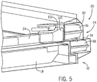
- FIG. 5 is a partial perspective view of a vehicle 10 with a lateral energy absorption system 12.
- the crossbeam 24 couples to one or both of the side beams 20.
- the side beam 20 couples to the upper side beam 32 to accommodate the battery 18.
- the crossbeam 24 may couple to the lower side beam 34.
- the crossbeams 24 may include enlarged ends 120 that couple to the crossbeam 24 and the side beam 20. As illustrated, the ends 120 have a larger cross-section than the rest of the crossbeam 24 increasing the contact area with the side beam 20.
- the ends may also form a taper 122.
- the taper 122 on the crossbeam 24 may form another crumple zone enabling the crossbeam 24 to gradually absorb energy from the side beams 20.
Applications Claiming Priority (2)
| Application Number | Priority Date | Filing Date | Title |
|---|---|---|---|
| US201662384298P | 2016-09-07 | 2016-09-07 | |
| US15/685,328 US10766536B2 (en) | 2016-09-07 | 2017-08-24 | Lateral energy absorption system |
Publications (1)
| Publication Number | Publication Date |
|---|---|
| EP3293084A1 true EP3293084A1 (en) | 2018-03-14 |
Family
ID=59811201
Family Applications (1)
| Application Number | Title | Priority Date | Filing Date |
|---|---|---|---|
| EP17189833.1A Withdrawn EP3293084A1 (en) | 2016-09-07 | 2017-09-07 | Lateral energy absorption system |
Country Status (3)
| Country | Link |
|---|---|
| US (1) | US10766536B2 (zh) |
| EP (1) | EP3293084A1 (zh) |
| CN (2) | CN208069806U (zh) |
Cited By (2)
| Publication number | Priority date | Publication date | Assignee | Title |
|---|---|---|---|---|
| DE102019130051A1 (de) * | 2019-11-07 | 2021-05-12 | Bayerische Motoren Werke Aktiengesellschaft | Bodengruppe für einen elektrisch betreibbaren Kraftwagen |
| WO2021089775A1 (de) * | 2019-11-07 | 2021-05-14 | Bayerische Motoren Werke Aktiengesellschaft | Bodengruppe für einen elektrisch betreibbaren kraftwagen |
Families Citing this family (10)
| Publication number | Priority date | Publication date | Assignee | Title |
|---|---|---|---|---|
| US10155542B2 (en) * | 2016-01-22 | 2018-12-18 | Ford Global Technologies, Llc | Stepped honeycomb rocker insert |
| US10336373B2 (en) | 2016-09-07 | 2019-07-02 | Thunder Power New Energy Vehicle Development Company Limited | Lateral energy absorption system |
| US10766536B2 (en) * | 2016-09-07 | 2020-09-08 | Thunder Power New Energy Vehicle Development Company Limited | Lateral energy absorption system |
| US10293860B1 (en) * | 2018-01-15 | 2019-05-21 | Ford Global Technologies, Llc | Rocker with internal crush pods |
| US11077812B2 (en) | 2018-02-27 | 2021-08-03 | GM Global Technology Operations LLC | Composite energy-absorbing assembly |
| US20190308669A1 (en) * | 2018-04-06 | 2019-10-10 | GM Global Technology Operations LLC | Composite underbody structure for vehicles |
| DE102018127368A1 (de) * | 2018-11-02 | 2020-05-07 | Benteler Automobiltechnik Gmbh | Schweller und Fahrzeugrahmen einer Fahrzeugkarosserie und Verfahren zur Herstellung eines Schwellers |
| JP7181799B2 (ja) * | 2019-01-16 | 2022-12-01 | 株式会社神戸製鋼所 | 車体構造 |
| US11833895B2 (en) | 2019-05-20 | 2023-12-05 | Canoo Technologies Inc. | Electric vehicle platform |
| JP7336544B2 (ja) * | 2019-07-02 | 2023-08-31 | カヌー・テクノロジーズ・インコーポレイテッド | 衝撃特徴部 |
Citations (2)
| Publication number | Priority date | Publication date | Assignee | Title |
|---|---|---|---|---|
| EP2860086A1 (en) * | 2012-06-08 | 2015-04-15 | Honda Motor Co., Ltd. | Fibre-reinforced plastic cabin for vehicle |
| WO2015129110A1 (ja) * | 2014-02-25 | 2015-09-03 | 本田技研工業株式会社 | 自動車の車体構造および車体フロアの製造方法 |
Family Cites Families (22)
| Publication number | Priority date | Publication date | Assignee | Title |
|---|---|---|---|---|
| US20020060462A1 (en) | 1998-07-02 | 2002-05-23 | Glance Patrick M. | Bumper beam absorber |
| WO2000030916A1 (en) | 1998-11-26 | 2000-06-02 | Lotus Cars Limited | A crash rail for a vehicle |
| IT1319049B1 (it) | 2000-10-18 | 2003-09-23 | Adlev Srl | Dispositivo per l'assorbimento di urti ad efficienza migliorata |
| GB0114684D0 (en) * | 2001-06-15 | 2001-08-08 | Dow Chemical Co | Automobile assembly |
| DE10234253B3 (de) * | 2002-07-27 | 2004-04-08 | Hydro Aluminium Deutschland Gmbh | Crashbox für Kraftfahrzeuge |
| US20060005503A1 (en) * | 2004-07-07 | 2006-01-12 | Jeffrey Bladow | Reinforced structural member and method for its manufacture |
| US20080098601A1 (en) | 2006-10-30 | 2008-05-01 | Shape Corporation | Tubular tapered crushable structures and manufacturing methods |
| US7874611B2 (en) * | 2008-04-03 | 2011-01-25 | GM Global Technology Operations LLC | Scalable two-piece reinforcement and method for producing same |
| DE102010003497B4 (de) * | 2010-03-31 | 2018-04-05 | Benteler Sgl Gmbh & Co. Kg | Verfahren zur Herstellung eines Aufprallschutzelementes |
| IT1401678B1 (it) | 2010-07-29 | 2013-08-02 | Tres Srl | Elemento ad assorbimento d'urto polimerico per un veicolo. |
| US8336933B2 (en) | 2010-11-04 | 2012-12-25 | Sabic Innovative Plastics Ip B.V. | Energy absorbing device and methods of making and using the same |
| US8322780B2 (en) * | 2010-12-20 | 2012-12-04 | Sabic Innovative Plastics Ip B.V. | Reinforced body in white and method of making and using the same |
| US8696051B2 (en) * | 2010-12-22 | 2014-04-15 | Tesla Motors, Inc. | System for absorbing and distributing side impact energy utilizing a side sill assembly with a collapsible sill insert |
| US8459726B2 (en) | 2011-04-15 | 2013-06-11 | Ford Global Technologies, Llc. | Multi-cornered strengthening members |
| DE102011051622B4 (de) * | 2011-07-07 | 2021-03-25 | Dr. Ing. H.C. F. Porsche Aktiengesellschaft | Verstärkungselement für eine Fahrzeugstruktur, insbesondere für einen Schweller eines Kraftfahrzeugs |
| CN203094197U (zh) * | 2012-11-26 | 2013-07-31 | 上海瑞珑汽车科技有限公司 | 一种轻量化电动汽车 |
| US8864216B2 (en) | 2013-01-18 | 2014-10-21 | Sabic Global Technologies B.V. | Reinforced body in white and method of making and using the same |
| US10183638B2 (en) * | 2014-03-12 | 2019-01-22 | Tres S.R.L. | Polymeric shock absorbing element for a vehicle and longitudinal side member |
| CN205022341U (zh) * | 2015-10-08 | 2016-02-10 | 北京汽车研究总院有限公司 | 一种车门防撞梁总成、车门及车辆 |
| CN105365887B (zh) * | 2015-12-16 | 2017-10-10 | 上汽通用五菱汽车股份有限公司 | 一种三腔体多层焊接前纵梁 |
| US10766536B2 (en) * | 2016-09-07 | 2020-09-08 | Thunder Power New Energy Vehicle Development Company Limited | Lateral energy absorption system |
| US10336373B2 (en) | 2016-09-07 | 2019-07-02 | Thunder Power New Energy Vehicle Development Company Limited | Lateral energy absorption system |
-
2017
- 2017-08-24 US US15/685,328 patent/US10766536B2/en active Active
- 2017-09-07 CN CN201721140735.XU patent/CN208069806U/zh not_active Expired - Fee Related
- 2017-09-07 EP EP17189833.1A patent/EP3293084A1/en not_active Withdrawn
- 2017-09-07 CN CN201710799018.6A patent/CN107792186A/zh active Pending
Patent Citations (2)
| Publication number | Priority date | Publication date | Assignee | Title |
|---|---|---|---|---|
| EP2860086A1 (en) * | 2012-06-08 | 2015-04-15 | Honda Motor Co., Ltd. | Fibre-reinforced plastic cabin for vehicle |
| WO2015129110A1 (ja) * | 2014-02-25 | 2015-09-03 | 本田技研工業株式会社 | 自動車の車体構造および車体フロアの製造方法 |
Cited By (2)
| Publication number | Priority date | Publication date | Assignee | Title |
|---|---|---|---|---|
| DE102019130051A1 (de) * | 2019-11-07 | 2021-05-12 | Bayerische Motoren Werke Aktiengesellschaft | Bodengruppe für einen elektrisch betreibbaren Kraftwagen |
| WO2021089775A1 (de) * | 2019-11-07 | 2021-05-14 | Bayerische Motoren Werke Aktiengesellschaft | Bodengruppe für einen elektrisch betreibbaren kraftwagen |
Also Published As
| Publication number | Publication date |
|---|---|
| US10766536B2 (en) | 2020-09-08 |
| CN107792186A (zh) | 2018-03-13 |
| US20180065677A1 (en) | 2018-03-08 |
| CN208069806U (zh) | 2018-11-09 |
Similar Documents
| Publication | Publication Date | Title |
|---|---|---|
| US10336373B2 (en) | Lateral energy absorption system | |
| US10766536B2 (en) | Lateral energy absorption system | |
| US9981541B2 (en) | Protection structure of battery module mounted in rear of vehicle body | |
| US8485592B2 (en) | Front connection structure for vehicle body | |
| US20210331641A1 (en) | Uniform deceleration unit crash box | |
| EP2366591B1 (en) | Shock absorbing device for vehicle with multiple shock absorbing stages | |
| US11097782B2 (en) | Sill beam uniform deceleration unit | |
| KR20210107682A (ko) | 차량의 로커 구조물 및 그 획득방법 | |
| GB2568538A (en) | Vehicle structural assemblies | |
| EP3130521B1 (en) | Cowcatcher and railroad vehicle provided with cowcatcher | |
| US11618505B2 (en) | Frame structure for an energy storage device including a deformation zone | |
| US11052848B2 (en) | Energy absorbing device | |
| JPH07165109A (ja) | 車両の車体構造 | |
| CN210526464U (zh) | 防撞缓冲吸能装置 | |
| CN104554481A (zh) | 车身前地板骨架及车辆 | |
| CN205554105U (zh) | 一种复合结构的汽车吸能盒 | |
| CN108725237B (zh) | 车辆 | |
| CN112590938B (zh) | 一种分层填充材料的汽车上纵梁及其使用方法和制造方法 | |
| CN212373311U (zh) | 一种汽车耐撞性的前端防撞结构装置 | |
| JP6112686B2 (ja) | 自動車の車体構造 | |
| CN214689761U (zh) | 一种碰撞能量管理车身结构 | |
| WO2023233929A1 (ja) | 車体側部構造 | |
| EP3470307A1 (en) | Shared safety cell for passenger cars | |
| CN112744297A (zh) | 一种碰撞能量管理车身结构 | |
| CN111703391A (zh) | 一种汽车前端的防撞结构装置 |
Legal Events
| Date | Code | Title | Description |
|---|---|---|---|
| PUAI | Public reference made under article 153(3) epc to a published international application that has entered the european phase |
Free format text: ORIGINAL CODE: 0009012 |
|
| AK | Designated contracting states |
Kind code of ref document: A1 Designated state(s): AL AT BE BG CH CY CZ DE DK EE ES FI FR GB GR HR HU IE IS IT LI LT LU LV MC MK MT NL NO PL PT RO RS SE SI SK SM TR |
|
| AX | Request for extension of the european patent |
Extension state: BA ME |
|
| 17P | Request for examination filed |
Effective date: 20180914 |
|
| RBV | Designated contracting states (corrected) |
Designated state(s): AL AT BE BG CH CY CZ DE DK EE ES FI FR GB GR HR HU IE IS IT LI LT LU LV MC MK MT NL NO PL PT RO RS SE SI SK SM TR |
|
| 17Q | First examination report despatched |
Effective date: 20190322 |
|
| STAA | Information on the status of an ep patent application or granted ep patent |
Free format text: STATUS: THE APPLICATION IS DEEMED TO BE WITHDRAWN |
|
| 18D | Application deemed to be withdrawn |
Effective date: 20191002 |