EP3292957A1 - Screwing tool with movable jaw - Google Patents
Screwing tool with movable jaw Download PDFInfo
- Publication number
- EP3292957A1 EP3292957A1 EP17166477.4A EP17166477A EP3292957A1 EP 3292957 A1 EP3292957 A1 EP 3292957A1 EP 17166477 A EP17166477 A EP 17166477A EP 3292957 A1 EP3292957 A1 EP 3292957A1
- Authority
- EP
- European Patent Office
- Prior art keywords
- hexagonal
- contact surfaces
- mouth
- jaws
- screwing tool
- Prior art date
- Legal status (The legal status is an assumption and is not a legal conclusion. Google has not performed a legal analysis and makes no representation as to the accuracy of the status listed.)
- Withdrawn
Links
Images


Classifications
-
- B—PERFORMING OPERATIONS; TRANSPORTING
- B25—HAND TOOLS; PORTABLE POWER-DRIVEN TOOLS; MANIPULATORS
- B25B—TOOLS OR BENCH DEVICES NOT OTHERWISE PROVIDED FOR, FOR FASTENING, CONNECTING, DISENGAGING OR HOLDING
- B25B13/00—Spanners; Wrenches
- B25B13/46—Spanners; Wrenches of the ratchet type, for providing a free return stroke of the handle
-
- B—PERFORMING OPERATIONS; TRANSPORTING
- B25—HAND TOOLS; PORTABLE POWER-DRIVEN TOOLS; MANIPULATORS
- B25B—TOOLS OR BENCH DEVICES NOT OTHERWISE PROVIDED FOR, FOR FASTENING, CONNECTING, DISENGAGING OR HOLDING
- B25B13/00—Spanners; Wrenches
- B25B13/02—Spanners; Wrenches with rigid jaws
- B25B13/08—Spanners; Wrenches with rigid jaws of open jaw type
-
- B—PERFORMING OPERATIONS; TRANSPORTING
- B25—HAND TOOLS; PORTABLE POWER-DRIVEN TOOLS; MANIPULATORS
- B25B—TOOLS OR BENCH DEVICES NOT OTHERWISE PROVIDED FOR, FOR FASTENING, CONNECTING, DISENGAGING OR HOLDING
- B25B13/00—Spanners; Wrenches
- B25B13/10—Spanners; Wrenches with adjustable jaws
- B25B13/12—Spanners; Wrenches with adjustable jaws the jaws being slidable
- B25B13/18—Spanners; Wrenches with adjustable jaws the jaws being slidable by cam, wedge, or lever
Definitions
- the invention relates to a screwing tool with a head and a pivotable about a pivot axis with the head so motion-coupled handle, the torque acting on the handle in a screwing a relation to a firmly connected to the head fixed jaw in a sliding direction movable jaw towards the solid Jaw subjected to force, wherein both jaws substantially transversely to the direction of extending, a mouth between the jaws limiting, extending in first reference planes, first contact surfaces, which are interrupted by a respective second and third contact surface forming corner recesses, wherein the second and third abutment surfaces in mutually angularly offset by 60 ° to each other first and second reference planes and offset by 30 ° to the first reference planes, so that on hexagonal sections of nuts or screws of different width across flats in a first torque-Einbring ein and in a second torque-insertion position offset by 30 ° in each case from at least two pressure zones formed by the contact surfaces on different polygonal surfaces of the hexagonal sections can be applied with a compress
- the DE 94 04 031.1 shows an adjustable wrench of the generic type.
- a material of the same material connected to the head fixed jaw and a relative to the fixed jaw movable jaw.
- the two jaws form mutually facing, substantially mutually parallel first contact surfaces for engagement with hexagonal surfaces of a nut, wherein the first contact surfaces run transversely to the direction of displacement.
- a corner recess interrupts the first contact surface in a mouth-side portion and a maulground stoolen portion, wherein the clear width of the mouth is defined by the distance of the mouth-opening side portions of the first contact surface.
- the maulground seasoneauen first contact surfaces have a greater distance from each other.
- the DE 200 07 561 U1 describes a similar screwing tool.
- the contact surfaces have additional profile ribs.
- the DE 931 580 describes a screwing tool with a fixed and a movable jaw, wherein the jaws from the mouth opening to the mouth base rectilinearly extending first contact surfaces.
- the DE 935 418 describes a screwing tool in which the sliding jaw is also displaced relative to the fixed jaw.
- the slidable jaw is spring biased with respect to the fixed jaw and has a tooth which engages a tooth gap of a short arm of a two-armed handle. If a torque is exerted on the handle about an axis of rotation, the displaceable jaw is subjected to a force in the direction of the fixed jaw.
- the movable jaw can move away from the fixed jaw, so that the screwing tool can be rotated by 60 ° relative to the hexagonal section resting in space, so that after the 60 ° rotation, the mutually parallel contact surfaces of the jaws on other hexagonal surfaces of the Hexagonal section abut.
- the screwing is thus usable in the manner of a gun.
- Adjustable wrenches are out of the US 1,048,298 and DE 1 931 580 previously known.
- the US 2,751,802 shows a ring spanner with a head stop that blocks a free axial displacement of the hexagonal portion relative to the contact surfaces.
- the invention has for its object to improve the mouth design of a generic screwing tools by screwing.
- the corner recess is located between two mutually aligned portions of the first contact surface.
- Each of the two jaws has a maulö réelles suren portion of the first contact surface and a maulground stoolen portion of the first contact surface, wherein the two sections are aligned with each other, that lie in a common first reference plane.
- the first reference planes can in the non-force-loaded state in the mouth opening direction small, about 2 converge to 3 degrees, so that they do not mathematically strictly parallel or mathematically strictly perpendicular to the direction of displacement.
- the deliberate deviation of the course of the first reference planes of a parallel or perpendicular direction to the displacement direction leads to a torque application and concomitant bending of the jaws to a parallel alignment of the two first reference planes, so that the reference planes at least when a screw head or a Nut with a torque parallel to each other.
- the maulground paragraphen sections and the jaw opening side portions have the same distance from each other.
- the clear width of the mouth is thus determined by the distance of the maulground remedyen sections of the first contact surfaces.
- the use of the screwing tool in the manner of a ratchet wrench is improved by this mouth design.
- the screw head or the nut can assume a radially tethered torque transmission position in the mouth, in which the corner regions of the hexagon nut or of the hexagonal screw head engage in the corner recesses.
- a non-constrained torque transmission position two mutually opposite flank sections of the hexagonal profile abut against the first contact surfaces.
- the screwing tool can be withdrawn from the screw head or from the nut in the radial direction without substantial removal of the two jaws.
- the screwing tool can be operated ratchet-like, with only a return angle of 30 ° is required to come from the radially unbelted first torque transmission position in one of these functionally adjacent radially bound second torque transmission position.
- the maul ground felte portion of the first contact surface is longer than the mouth opening side distance. Furthermore, it can be provided that the maulground discoverede section is longer than the width of the corner recess. Particularly preferably, the maulground discoverede portion of the first contact surface is at least twice as long as the width of the Corner recess. As a result of this configuration, the range of wrench sizes has been increased by nuts or hex bolts that can be screwed with the adjustable wrench.
- the maulground worne portion of the first contact surface has a length such that the flanks of the hexagonal sections with the largest spanner size, which can be screwed with the wrench can rest with its entire length to the maulground remedyen portions of the first contact surface.
- the corner recesses then take in the radially bound torque-transfer position only the corner regions of the hexagonal profiles of nuts or screw heads.
- the flanks of the corner recesses are formed by second and third abutment surfaces which are angularly offset from each other by 60 ° and by 30 ° relative to the first abutment surface.
- diametrically opposite hexagonal surface sections of the hexagonal section are located on first contact surfaces of the first reference plane running transversely to the displacement direction of the displaceable jaw.
- diametrically opposite corner regions of the hexagonal section are diametrically opposite corner regions of the hexagonal section in corner recesses of two jaws, which are each formed by contact surfaces of the second and third reference plane. These corner recesses can lie between two contact surfaces of the first reference plane. If such a design rotates a nut or a screw head in a ratchet-like manner of actuation, that is, pivots it back and forth, then the hexagonal section of the nut or of the screw head performs a radial movement within the mouth.
- the attack on the opposite first contact surfaces takes place in a position remote from the mouth opening of the hexagonal section.
- the attack on the opposite corner recesses on the hexagonal section takes place in a closer to the opening of the mouth position of the hexagonal section.
- In the ratcheting screw actuation of the hexagonal portion thus migrates in the mouth extension direction between two positions back and forth, in a first position, two opposing polygonal edges of the hexagonal portion abut first abutment surfaces and eino in a second position corner portions of the polygonal section in Eckaussparungen.
- further contact surfaces are provided.
- the contact surfaces are then arranged in such a way that when applying a torque to a bound by the jaws hexagon section with at least three adjacent to different hexagonal surfaces, each formed by a contact surface pressure zones a compressive force is applied to the hexagonal surface.
- the further contact surfaces may extend along further reference planes, which occupy a 30 ° angle to one of the first, second or third reference plane.
- the second and third abutment surfaces preferably form on the jaws associated therewith corner recesses for receiving the corner region of the hexagonal section of the nut or of the screw head.
- the Eckaussparines are preferably each between first contact surfaces. It can be provided more Eckausspar urge in which eino corner portions of the hexagonal portion in the radially unbelted torque transmission position.
- the contact surfaces form a total the sidewalls of an open mouth.
- the mouth opening detection bevels are provided, which extend V-shaped to each other.
- the finding slopes each have an angle which may be 30 ° to the respective first reference plane, which run perpendicular to the movable jaw.
- the slidable jaw can be spring-loaded by a spring element in the direction of the fixed jaw. It may be provided a second, weaker spring element which acts in the opposite direction.
- the spring element may be a helical gear compression spring, which is arranged in a spring receiving chamber which is closed by a plug.
- the spring element can be supported on the plug.
- the kinematic coupling of the pivotable jaw to the handle can be done via a tooth which engages in a tooth gap.
- the tooth may be associated with the slidable jaw and the gap between the teeth with a short arm of the two-armed handle. It is also provided a head stop, which can take an active position and a Toonoch sacred too. In the non-operating position, the hexagonal portion can move freely through the mouth between the two jaws, wherein the contact surfaces abut the hexagonal surfaces. In an active position of the head stop, an end face of the hexagonal section is supported on a stop face of the head stop, so that the hexagonal section is fixed to the head at least in an axial direction.
- the head stop can be associated with a stop slider, which is linearly displaceable or slidably mounted on the fixed jaw about an axis.
- the head stop covers only one of the Eckaussparungen in its operative position, so that the axial bondage is limited to one of the two torque transmission positions and in particular to the radially tethered torque transmission position.
- diverging determination slopes adjoin the mouth-opening-side ends of the mouth-opening-side sections of the first contact surfaces in the mouth opening direction. The detection slopes facilitate the radial attachment of the jaws to a screw head or a nut.
- the maulground skillen ends of the maulground paragraphen Connect sections of the first contact surfaces oblique contact surfaces on which flanks of the hexagonal profiles of screws or nuts can create, if they are taken in the radially unbelted torque transmission position. These contact surfaces have a 60 ° angle to the first contact surfaces.
- the screwing tools shown in the drawings are capable of turning screws with a hexagon head or hexagon nuts of different width across flats in a screwing direction. Will the screwing tool rotated against the screwing direction in a freewheeling direction, the profiled jaws 4, 5 of the mouth 10 overflow the hexagonal corners in order to be able to be attached to a different position of the hexagonal section. While in the prior art, the screwing must be turned back by at least 60 ° in the freewheeling direction, so that the jaws 4, 5 can again enter into a captivating attack on the hexagonal profile, sufficient in the screwing invention a pivoting movement in the freewheeling direction by 30 °.
- the screwing tool can engage in two mutually different torque transmission positions on the hexagonal portion of the nut or the screw head to transmit a torque, namely in a first torque transmission position, as they FIG. 8 shows and in a second torque transmission position, like the FIG. 10 shows. Both positions differ by a 30 ° twist of the hexagonal section 30 within the mouth 10 of the screwing tool.
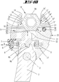
- the screwing tool consists of an elongated, made of steel handle 2, which forms a two-armed lever which is mounted about a pivot axis 3 pivotally mounted on a head 1 also made of steel.
- the long arm of the handle 2 may be encompassed by a user's hand.
- the short arm of the handle 2 has a tooth gap 16 into which a tooth 15 of a relative to the head 1 in a direction V displaceable body engages.
- This displaceable body forms a displaceable jaw 5, which can be displaced relative to a fixed jaw 4, which is connected to the head 1 in the same material, when the handle 2 is pivoted about the pivot axis 3.
- a guide portion of the jaw 5 engages positively in a guide channel of the head 1, so that the displaceable jaw 5 is assigned linearly displaceable head 1. It is provided a spring receiving chamber 7, in which a helical gear compression spring 6 rests.
- the spring receiving chamber 7 is closed by a plug 8 and extends in the direction of displacement V. At the plug 8, one end of the spring element 6 is supported. The other end acts on the movable jaw 5 in the direction of the fixed jaw 4th
- the walls of the mouth 10 consist of a plurality of contact surfaces 11, 11 ', 12, 12', 13, 13 ', 18, 19, 25, 29, 31.
- Each of the two jaws 4, 5 has a first contact surface 11, 11th '.
- the contact surface 11 as well as the contact surface 11 'of a corner recess 24, 24' interrupted in two isolated first contact surfaces 11 and 11 '.
- the first contact surfaces 11, 11 'each extend along a reference plane a, a'. This first reference plane a, a 'extends substantially, ie with a deviation of +/- 2 degrees transversely to the displacement direction V.
- the reference plane a which is associated with the movable jaw, thus extends substantially, ie with a deviation from 0 to -4 degrees parallel to the reference plane a ', which is assigned to the fixed jaw 4.
- the two reference planes a, a ' form a reference plane pair.
- FIG. 8 shows a hexagonal portion which is held in a non-radially bound torque transmission position of the jaws 4, 5.
- Two mutually opposite, mutually parallel hexagonal surfaces of the hexagonal section lie in surface contact with the first contact surfaces 11, 11 '.
- the hexagonal section 30 can be pulled out of the mouth 10 in the radial direction with respect to the insertion direction of a screw having the hexagonal section 30. The two hexagonal surfaces then slide along the mutually parallel first contact surfaces 11 along.
- the contact surface 18 forms, together with the contact surface 11 ', a corner recess 27.
- the contact surface 19 of the movable jaw 5 forms together with contact surface 11 a corner recess 26. Corner regions of the hexagonal section 30 lie in these two corner recesses when the jaws 4, 5 engage the hexagonal section 30 in the non-radially constrained torque transmission position. If a torque is applied to the handle 2 in a clockwise direction, the tooth engagement causes the displaceable jaw 5 to be acted upon in the direction of the fixed jaw 4.
- FIG. 9 An inclined surface adjoins the abutment surface 25, which forms a sliding surface 32, on which an edge of the hexagonal section 30 can slide along during the pivoting back of the handle.
- the sliding surface 32 can be offset by 30 degrees to the contact surface 29. It lies opposite the contact surface 31.
- FIG. 10 shown operating position After a pivoting of 30 ° relative to the in FIG. 8 shown position is the in FIG. 10 shown operating position, in which the jaws 4, 5 in a second torque transmission position, which is here a radially captive torque transmission position, engage the hexagonal portion 30.
- corner recesses 24, 24 'a Two diametrically opposite corner regions of the hexagonal section 30 are now each in opposite corner recesses 24, 24 'a. These are the corner recesses 24, 24 ', which interrupt the two first contact surfaces 11, 11' approximately centrally.
- the two flanks of the corner recesses 24, 24 ' are formed by second contact surfaces 12, 12' and third contact surfaces 13, 13 '.
- the third contact surfaces 13, 13 'extend along third reference planes c, c', which are also inclined by 30 ° with respect to the first reference plane a, a ' are.
- the third reference planes c, c 'and second reference planes b, b' intersect at an angle of 60 and 120 °, respectively.
- Each of the two jaws 4, 4 ' has at least one second contact surface 2, 2' and at least one third contact surface 13, 13 ', the respective reference planes c, c' and b, b 'extending parallel to one another.
- the second reference plane b ' extends over a contact surface 12' and a contact surface 31, wherein between the contact surfaces 12 'and 31 a further corner recess 27 is located, in which a multi-corner of the hexagonal portion 30 in the in FIG. 8 shown torque transmission position rests.
- the contact surfaces 13 ', 31, 25 and 13 respectively form pressure zones P to transmit torque to the hexagonal section 30. While at the in the FIG. 8 shown torque transfer position three pressure zones P act on the hexagonal portion 30, acting in the in FIG. 10 shown second torque transmission position four pressure zones P, wherein each of the two jaws 4, 5 are associated with two pressure zones.
- second torque transmission position are a total of three corner regions of the hexagonal section 30 in corner recesses 24, 28 and 24 ', wherein the corner recess 28 is formed by the contact surfaces 25 and 29, the contact surface 29 extends in the third reference plane c and the contact surface 25 in a further reference plane, which is inclined relative to the third reference plane c by 60 ° or 120 °.
- a stopper slide 22 On the fixed jaw 4 is a stopper slide 22, the of a Tinwirk ein as the FIG. 3 shows, in an operative position, which the FIG. 4 shows, can be pushed.
- a head stop 23 projects in the operative position, a head stop 23 into the mouth 10 into which a broad side surface of the hexagonal portion 30 can be supported, so that the hexagonal portion 30 forming nut or screw is bound in the mouth 10 in the axial direction.
- the head stop 23 can engage over the corner recess 27 and / or the corner recess 24 '.
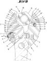
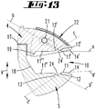
- FIG. 13 shows a further optimized embodiment in which as well as in the embodiment described above, a first contact surface of the fixed jaw 4 has a first contact surface having a mouth opening side portion 11 'and a maulground stoolen portion 11'''.
- the two sections 11 ', 11''' lie in a common reference plane a.
- the reference plane a extends substantially transversely to the direction of displacement V, that is also here with a deviation of +/- 2 degrees to the vertical of the direction of displacement V.
- the sliding jaw 5 also has a two-section first contact surface.
- a mouth-opening-side section 11 runs in alignment with a base-side-side section 11 ".
- the two sections 11, 11" extend in a reference plane a '.
- the reference plane a ' also extends substantially transversely to the displacement direction V, ie with a deviation of +/- 2 degrees to the vertical.
- the reference planes a, a ' are substantially parallel to each other, wherein they converge slightly in the unaugmented state in the mouth opening direction, wherein the convergence angle is 0 to 4 degrees.
- the length of the base-side-side sections 11 ", 11 '''measured in the direction of the mouth extension is greater than the length of the mouth-opening-side sections 11, 11' measured in the mouth extension direction.
- the length of the maulground paragraphen sections 11 ", 11 '' ' is also greater than the width measured in the mouth extension direction of the Eckaussparungen 24, 24', ie the distance between the two in a common reference plane a, a 'lying portions 11', 11 '' 'or 11, 11 ".
- detection bevels 14, 14 ' are provided, which in each case adjoin the mouth-opening-side ends of the mouth-opening-side sections 11,11' of the first contact surface.
- the finding slopes 14, 14 ' diverge from each other in the mouth opening direction and facilitate the attachment of the screwing tool on a screw or a nut.
- the screwing tool is able to attack like a wrench on a hexagonal profile, wherein the two jaws 4, 5 are pushed onto the screw head in the radial direction, ie in the mouth extension direction, on the hexagonal profile.
- the two jaws 4, 5 spaced from each other, which is a consequence of the emergence of the detection bevels 14, 14 'on the hexagonal profile.
- the screwing is pushed into a stop position on the hexagonal profile by the edges abut the contact surfaces 18,19. Further flanks running parallel to one another then abut against the base-side-side sections 11 ", 11" of the first contact surface, the length of which preferably corresponds to the flank length of the hexagonal profile with the largest flatscrew.
- the corner regions of the hexagonal profile thus find the corner recesses 24, 24 ', the hexagonal profile shifting slightly in the mouth opening direction until opposite corner regions of the hexagonal profile rest in the opposite corner recesses 24, 24'.
- the hexagonal profile can then be further screwed in this radially bound torque transmission position in a screwing direction, with a subsequent backward displacement of the screwing tool by 30 °, glide p mutually parallel flanks of the hexagonal profile again in a two-dimensional contact with the first contact surfaces 11,11 ', wherein the hexagonal profile slightly in Radialein Introduceraum relative to the pivot axis, ie toward the mouth base, relocate until the flanks of the hexagonal profile over its entire length abut the maulground stoolen sections 11 ", 11 '' 'of the first contact surface.
- a screwing tool which is characterized in that each of the two jaws 4, 5 respectively second 12, 12 ', 31 and third 13, 13', 29 contact surfaces formed, each in a second b, b 'and a third c, c 'Reference plane extending, each extending parallel to each other, wherein the second b, b' and third c, c 'reference planes with respect to the plane of rotation respectively to the first reference planes a, a' at an angle ⁇ , ⁇ of 30 ° and to each other in one Angle y + ⁇ of 60 °, so that on hexagonal portions 30 of nuts or screws of different wrench size in a first torque-Einbringhyroid and offset by 30 ° second torque-Einbring ein each of at least two pressure zones formed by the contact surfaces P at different Polygonal surfaces of the hexagonal sections 30 a compressive force can be applied.
- a screwing tool which is characterized in that the corner recesses 24, 24 'respectively between a mouth-side portion 11, 11' and an aligned maulground documenten portion 11 ", 11 '' 'of the first contact surface 11, 11', wherein the inside diameter of the mouth 10, the distance between the two maulground technologyen sections 11 ", 11 '' '.
- a screwing tool which is characterized in that the maulground solution 11 ", 11 '''are longer than the mouth opening side portions 11, 11' of the first contact surfaces 11,11 ', 11", 11''' .
- a screwing tool which is characterized in that the maulground patenten sections 11 ", 11 '''are longer than the width of the Eckaussparitch 24, 24'.
- a screwing tool which is characterized in that the maulground patenten portions 11 ", 11 '' 'at least twice as long as the width of the Eckaussparitch 24, 24'.
- a screwing tool which is characterized in that the mouth opening has finding bevels 14, 14 ', which adjoin one another divergently in the mouth opening direction, respectively, to the mouth-opening-side section 11, 11' of the first contact surfaces 11, 11 '.
- a screwing tool which is characterized in that the first, second and third and further contact surfaces 11, 11 '; 12, 12 ', 13, 13', 29; 18, 25, 31 are arranged such that when exerting a torque on the hexagonal portion 30 held by the jaws 4, 5, a pressure force is applied to the hexagonal surface on at least three pressure surfaces P acting on different hexagonal surfaces 20, each formed by a contact surface.
- a screwing tool which is characterized in that the further contact surfaces 18, 25, 29 either in one of the first, second or third reference plane a, a ', b, b', c, c 'lie or in a further reference plane, the order 30 ° inclined to a first, second or third reference plane extends.
- a screwing tool which is characterized in that between two first contact surfaces 11, 11 ', between two second contact surfaces 12, 12' and between two third contact surfaces 13,13 'each have a corner recess 24, 24', 27, 26, wherein the in the radially unbelted second torque transmission position two mutually parallel hexagonal surfaces on the first contact surfaces 11, 11 'bear and in the radially bound torque transmission position two diametrically opposite corner regions of the hexagonal section in the Eckaussparitch 24, 24' eino.
- a screwing tool which is characterized in that the contact surfaces 11, 11 ', 12, 12', 31, 13, 13 ', 29, 18, 25 form the side walls of an open mouth 10, the mouth opening of which has chamfers 14, 14', which are inclined to the first reference planes a, a '.
- a screwing tool which is characterized by a head stop 23 associated with one of the jaws 4, which moves from an out of action position in which a hexagonal section 30, which is bound by the jaws 4, 5, in an axial direction between the jaws 4, 5, into an operative position can be brought, in which the head stop 23 blocks the axial displaceability of the hexagonal portion 30 by an end face of the hexagonal portion 30 abuts the head stop 23.
- a screwing tool which is characterized by a spring element 6, with which the displaceable jaw 5 is subjected to force in the direction of the fixed jaw 4.
- a screwing tool which is characterized in that, when the handle 2 is pivoted counter to the screwing direction, the abutment surfaces 11, 11 ', 12, 12', 31, 13, 13 ', 29, 18, 25, which abut the hexagonal surfaces 20 of the hexagonal section 30 from the hexagonal surface, so that opposite corner portions of the hexagonal portion 30 slide along abutment surfaces to change the torque transmission position.
- a screwing tool which is characterized in that a tooth 15 assigned to the displaceable jaw 4 engages in a tooth gap 16 of a short arm of the two-armed handle 2.
- a screwing tool which is characterized in that between the corner recesses 24, 24 'and that of the opening of the mouth 10th pointing base of the mouth 10 measured length of the first contact surfaces 11 ', 11''' is dimensioned such that at a particular 30 degrees amount of reciprocating movement of the screwing a between the jaws 4, 5 seized hexagonal section when changing between a flank of the hexagonal section on the contact surfaces 11 ", 11 '''and an engagement of the corner regions of the hexagonal section in the Eckaussparitch in the extension direction of the mouth 10 moves back and forth.
Landscapes
- Engineering & Computer Science (AREA)
- Mechanical Engineering (AREA)
- Details Of Spanners, Wrenches, And Screw Drivers And Accessories (AREA)
Abstract
Die Erfindung betrifft ein Schraubwerkzeug mit einem Kopf (1) und einem um eine Schwenkachse (3) schwenkbar mit dem Kopf (1) derart bewegungsgekoppelten Griff (2), wobei zwei Backen (4, 5) im Wesentlichen quer zur Verschieberichtung (V) sich erstreckende, ein Maul (10) zwischen den Backen (4, 5) begrenzende Anlageflächen (11, 11', 11", 11''') aufweisen, die von Eckaussparungen (24, 24') unterbrochen sind. Auf Sechskantabschnitte (30) von Muttern oder Schrauben verschiedener Schlüsselweite ist in einer ersten Drehmoment-Einbringstellung und in einer dazu um 30° versetzten zweiten Drehmoment-Einbringstellung jeweils von mindestens zwei von den Anlageflächen gebildeten Druckzonen (P) an verschiedenen Mehrkantflächen der Sechskantabschnitte (30) eine Druckkraft aufbringbar. Die maulgrundseitigen Abschnitte (11", 11''') sind mindestens zweimal so lang sind wie die Weite der Eckaussparungen (24, 24').The invention relates to a screwing tool having a head (1) and a handle (2) pivotable about the head (1) about a pivot axis (3), wherein two jaws (4, 5) are substantially transverse to the direction of displacement (V) extending, a mouth (10) between the jaws (4, 5) limiting abutment surfaces (11, 11 ', 11 ", 11' ''), which are interrupted by corner recesses (24, 24 ') on hexagonal sections (30). of nuts or screws of different wrench size is in a first torque-insertion position and in a offset by 30 ° second torque insertion position of at least two pressure zones formed by the contact surfaces (P) at different polygonal surfaces of the hexagonal portions (30) a compressive force applied maulgrundseitigen sections (11 ", 11 '' ') are at least twice as long as the width of the corner recesses (24, 24').
Description
Die Erfindung betrifft ein Schraubwerkzeug mit einem Kopf und einem um eine Schwenkachse schwenkbar mit dem Kopf derart bewegungsgekoppelten Griff, das eine Drehmomentbeaufschlagung auf den Griff in einer Schraubrichtung eine gegenüber einer fest mit dem Kopf verbundenen festen Backe in einer Verschieberichtung verschieblichen Backe in Richtung auf die feste Backe kraftbeaufschlagt, wobei beide Backen im Wesentlichen quer zur Verschieberichtung sich erstreckende, ein Maul zwischen den Backen begrenzende, in ersten Bezugsebenen verlaufende, erste Anlageflächen aufweisen, die von jeweils eine zweite und eine dritte Anlagefläche ausbildenden Eckaussparungen unterbrochen sind, wobei die zweiten und dritten Anlageflächen in um 60° zueinander winkelversetzten ersten und zweiten Bezugsebenen und um 30° versetzt zu den ersten Bezugsebenen verlaufen, so dass auf Sechskantabschnitte von Muttern oder Schrauben verschiedener Schlüsselweite in einer ersten Drehmoment-Einbringstellung und in einer dazu um 30° versetzten zweiten Drehmoment-Einbringstellung jeweils von mindestens zwei von den Anlageflächen gebildeten Druckzonen an verschiedenen Mehrkantflächen der Sechskantabschnitte eine Druckkraft aufbringbar ist.The invention relates to a screwing tool with a head and a pivotable about a pivot axis with the head so motion-coupled handle, the torque acting on the handle in a screwing a relation to a firmly connected to the head fixed jaw in a sliding direction movable jaw towards the solid Jaw subjected to force, wherein both jaws substantially transversely to the direction of extending, a mouth between the jaws limiting, extending in first reference planes, first contact surfaces, which are interrupted by a respective second and third contact surface forming corner recesses, wherein the second and third abutment surfaces in mutually angularly offset by 60 ° to each other first and second reference planes and offset by 30 ° to the first reference planes, so that on hexagonal sections of nuts or screws of different width across flats in a first torque-Einbringstellung and in a second torque-insertion position offset by 30 ° in each case from at least two pressure zones formed by the contact surfaces on different polygonal surfaces of the hexagonal sections can be applied with a compressive force.
Die
Ein ähnliches Schraubwerkzeug wird in der
Die
Die
Die
Verstellbare Schraubenschlüssel sind aus den
Mit dem eingangs genannten Schraubwerkzeug lassen sich Muttern bzw. Sechskantschraubköpfe in 30° versetzt zueinander stehenden Winkelstellungen greifen, um ein Drehmoment auf die Mutter oder den Schraubenkopf zu übertragen.With the above-mentioned screwing can be nuts or Hexagon Schraubkopf in 30 ° staggered angular positions engage to transmit torque to the mother or the screw head.
Der Erfindung liegt die Aufgabe zugrunde, die Maulgestaltung eines gattungsgemäßen Schraubwerkzeugen schraubtechnisch zu verbessern.The invention has for its object to improve the mouth design of a generic screwing tools by screwing.
Gelöst wird die Aufgabe durch die in den Ansprüchen angegebene Erfindung, wobei die Unteransprüche nicht nur vorteilhafte Weiterbildungen des im Hauptanspruch angegebenen Schraubwerkzeuges, sondern auch eigenständige Lösungen der Aufgabe darstellen.The object is achieved by the invention specified in the claims, wherein the dependent claims represent not only advantageous developments of the screwing tool specified in the main claim, but also independent solutions to the problem.
Zunächst und im Wesentlichen wird vorgeschlagen, dass die Eckaussparung zwischen zwei miteinander fluchtenden Abschnitten der ersten Anlagefläche liegt. Jede der beiden Backen besitzt einen maulöffnungsseitigen Abschnitt der ersten Anlagefläche und einen maulgrundseitigen Abschnitt der ersten Anlagefläche, wobei die beiden Abschnitte miteinander fluchten, also in einer gemeinsamen ersten Bezugsebene liegen. Die ersten Bezugsebenen können im nicht kraftbeaufschlagten Zustand in Maulöffnungsrichtung geringförmig, etwa um 2 bis 3 Grad konvergieren, so dass sie nicht mathematisch streng parallel oder mathematisch streng senkrecht zur Verschieberichtung verlaufen. Die bewusste Abweichung des Verlaufs der ersten Bezugsebenen von einer Parallelität bzw. senkrechten Richtung zur Verschieberichtung führt bei einer Drehmoment-Beaufschlagung und einer damit einhergehenden Verbiegung der Backen zu einer Parallelausrichtung der beiden ersten Bezugsebenen, so dass die Bezugsebenen zumindest bei der Beaufschlagung eines Schraubenkopfs oder einer Mutter mit einem Drehmoment parallel zueinander verlaufen. Zumindest bei einer Drehmoment-Beaufschlagung haben die maulgrundseitigen Abschnitte und die maulöffnungsseitigen Abschnitte denselben Abstand voneinander. Die lichte Weite des Maules wird somit durch den Abstand der maulgrundseitigen Abschnitte der ersten Anlageflächen bestimmt. Die Verwendung des Schraubwerkzeuges in der Art eines Ratschenschlüssels ist durch diese Maulgestaltung verbessert. Der Schraubenkopf bzw. die Mutter kann in dem Maul eine radial gefesselte Drehmoment-Übertragungsstellung einnehmen, bei der die Eckbereiche der Sechskantmutter bzw. des Sechskantschraubenkopfes in den Eckaussparungen einliegen. In einer radial nicht gefesselten Drehmoment-Übertragungsstellung liegen zwei sich gegenüberliegende Flankenabschnitte des Sechskantprofils an den ersten Anlageflächen an. Das Schraubwerkzeug kann ohne eine wesentliche Entfernung der beiden Backen voneinander vom Schraubenkopf oder von der Mutter in Radialrichtung abgezogen werden. Gleichwohl kann das Schraubwerkzeug ratschenartig betätigt werden, wobei lediglich ein Rückdrehwinkel von 30° erforderlich ist, um von der radial nicht gefesselten ersten Drehmoment-Übertragungsstellung in einer dieser funktionell benachbart liegenden radial gefesselten zweiten Drehmoment-Übertragungsstellung zu kommen. In einer Weiterbildung der Erfindung ist vorgesehen, dass der maulgrundseitige Abschnitt der ersten Anlagefläche länger ist, als der maulöffnungsseitige Abstand. Ferner kann vorgesehen sein, dass der maulgrundseitige Abschnitt länger ist, als die Weite der Eckaussparung. Besonders bevorzugt ist der maulgrundseitige Abschnitt der ersten Anlagefläche mindestens zweimal so lang wie die Weite der Eckaussparung. Zufolge dieser Ausgestaltung ist das Spektrum der Schlüsselweiten von Muttern oder Sechskantschrauben vergrößert worden, die mit dem verstellbaren Schraubenschlüssel geschraubt werden können. Es ist insbesondere vorgesehen, dass der maulgrundseitige Abschnitt der ersten Anlagefläche eine derartige Länge aufweist, dass die Flanken der Sechskantabschnitte mit der größten Schlüsselweite, die mit dem Schraubenschlüssel schraubbar sind, mit ihrer gesamten Länge an die maulgrundseitigen Abschnitte der ersten Anlagefläche anliegen können. Die Eckaussparungen fassen dann in der radial gefesselten Drehmoment-Übertragungsstellung lediglich die Eckbereiche der Sechskantprofile von Muttern oder Schraubenköpfen. Die Flanken der Eckaussparungen werden hierzu von zweiten und dritten Anlageflächen ausgebildet, die untereinander um 60° und gegenüber der ersten Anlagefläche um 30° winkelversetzt sind. Mit dieser Anordnung wird erreicht, dass auf Sechskantabschnitte von Schrauben oder Muttern verschiedener Schlüsselweite in zwei verschiedenen Drehmoment-Übertragungsstellungen, nämlich in einer radial nicht gefesselten und in einer radial gefesselten Drehmoment-Übertragungsstellung jeweils von mindestens zwei von den Anlageflächen gebildeten Druckzonen an verschiedenen Mehrkantflächen ein Drehmoment aufbringbar ist. Die Druckzonen werden dabei von den Anlageflächen gebildet. In der radial nicht gefesselten Drehmomentstellung kann das Schraubwerkzeug in radialer Richtung vom Sechskantabschnitt abgezogen werden, ohne dass die beiden Backen voneinander entfernt werden müssen. In der radial gefesselten Drehmomentstellung ist dies nicht möglich. Hier kann das Schraubwerkzeug nur in axialer Richtung vom Sechskantabschnitt abgezogen werden oder es müssen zuvor die beiden Backen voneinander beabstandet werden. In der radial nicht gefesselten Drehmoment-Übertragungsstellung liegen diametral gegenüberliegende Sechskantflächenabschnitte des Sechskantabschnittes an quer zur Verschieberichtung der verschieblichen Backe verlaufenden ersten Anlageflächen der ersten Bezugsebene. In der radial gefesselten Drehmoment-Übertragungsstellung liegen sich diametral gegenüberliegende Eckbereiche des Sechskantabschnittes in Eckaussparungen der beiden Backen, die jeweils von Anlageflächen der zweiten und dritten Bezugsebene gebildet sind. Diese Eckaussparungen können zwischen zwei Anlageflächen der ersten Bezugsebene liegen. Wird mit einer derartigen Ausgestaltung eine Mutter oder ein Schraubenkopf in einer ratschenartigen Betätigungsweise gedreht, also hin und her geschwenkt, so vollführt der Sechskantabschnitt der Mutter oder des Schraubenkopfes innerhalb des Maules eine Radialbewegung. Der Angriff an den sich gegenüberliegenden ersten Anlageflächen erfolgt in einer der Maulöffnung entfernten Position des Sechskantabschnittes. Der Angriff über die sich gegenüberliegenden Eckaussparungen am Sechskantabschnitt erfolgt in einer der Öffnung des Maules näheren Position des Sechskantabschnittes. Bei der ratschenenden Schraubbetätigung wandert der Sechskantabschnitt somit in Maulerstreckungsrichtung zwischen zwei Positionen hin und her, wobei in einer ersten Position zwei sich gegenüberliegende Mehrkantflanken des Sechskantabschnittes an ersten Anlageflächen anliegen und in einer zweiten Position Eckbereiche des Mehrkantabschnittes in Eckaussparungen einliegen. In einer Weiterbildung der Erfindung ist vorgesehen, dass zusätzlich zu den ersten, zweiten und dritten Anlageflächen weitere Anlageflächen vorgesehen sind. Die Anlageflächen sind dann insgesamt derart angeordnet, dass beim Ausüben eines Drehmomentes auf einen von den Backen gefesselten Sechskantabschnitt mit mindestens drei an verschiedenen Sechskantflächen anliegenden, jeweils von einer Anlagefläche gebildeten Druckzonen eine Druckkraft auf die Sechskantfläche aufgebracht wird. Die weiteren Anlageflächen können sich entlang weiterer Bezugsebenen erstrecken, die einen 30° Winkel zu einer der ersten, zweiten oder dritten Bezugsebene einnehmen. Die zweiten und dritten Anlageflächen bilden an den ihnen zugeordneten Backen vorzugsweise Eckaussparungen zur Aufnahme des Eckbereiches des Sechskantabschnittes der Mutter oder des Schraubenkopfes. Die Eckaussparungen liegen bevorzugt jeweils zwischen ersten Anlageflächen. Es können weitere Eckaussparungen vorgesehen sein, in denen Eckabschnitte des Sechskantabschnittes auch in der radial nicht gefesselten Drehmoment-Übertragungsstellung einliegen. Die Anlageflächen bilden insgesamt die Seitenwände eines offenen Maules aus. Im Bereich der Maulöffnung sind Findungsschrägen vorgesehen, die zueinander V-förmig verlaufen. Die Findungsschrägen besitzen jeweils einen Winkel, der 30° betragen kann, zu der jeweils ersten Bezugsebene, die senkrecht zur verschieblichen Backe verlaufen. Die verschiebliche Backe kann von einem Federelement in Richtung auf die feste Backe federkraftbeaufschlagt sein. Es kann ein zweites, schwächeres Federelement vorgesehen sein, das in Gegenrichtung wirkt. Das Federelement kann eine Wendelgang-Druckfeder sein, die in einer Federaufnahmekammer angeordnet ist, die von einem Stopfen verschlossen ist. Das Federelement kann sich an dem Stopfen abstützen. Die kinematische Kopplung der verschwenkbaren Backe an den Griff kann über einen Zahn erfolgen, der in eine Zahnlücke eingreift. Der Zahn kann der verschieblichen Backe zugeordnet sein und die Zahnlücke einem kurzen Arm des zweiarmigen Griffs. Es ist ferner ein Kopfanschlag vorgesehen, der eine Wirkstellung und eine Außerwirkstellung einnehmen kann. In der Außerwirkstellung kann sich der Sechskantabschnitt frei durch das Maul zwischen den beiden Backen bewegen, wobei die Anlageflächen an den Sechskantflächen anliegen. In einer Wirkstellung des Kopfanschlages stützt sich eine Stirnfläche des Sechskantabschnittes an einer Anschlagfläche des Kopfanschlages ab, so dass der Sechskantabschnitt zumindest in einer Axialrichtung an den Kopf fixiert ist. Der Kopfanschlag kann einem Anschlagschieber zugeordnet sein, der linear verschieblich oder um eine Achse verschieblich an der festen Backe sitzt. Es kann vorgesehen sein, dass der Kopfanschlag in seiner Wirkstellung nur eine der Eckaussparungen überdeckt, so dass die axiale Fesselung auf eine der beiden Drehmoment-Übertragungsstellungen und insbesondere auf die radial gefesselte Drehmoment-Übertragungsstellung beschränkt ist. In einer Weiterbildung der Erfindung schließen sich an die maulöffnungsseitigen Enden der maulöffnungsseitigen Abschnitte der ersten Anlageflächen jeweils in Maulöffnungsrichtung divergierende Findungsschrägen an. Die Findungsschrägen erleichtern das radiale Ansetzen der Backen an einen Schraubenkopf oder eine Mutter. Es ist ferner vorgesehen, dass sich an die maulgrundseitigen Enden der maulgrundseitigen Abschnitte der ersten Anlageflächen schräg verlaufende Anlageflächen anschließen, an denen sich Flanken der Sechskantprofile von Schrauben oder Muttern anlegen können, wenn diese in der radial nicht gefesselten Drehmoment-Übertragungsstellung gefasst werden. Diese Anlageflächen besitzen einen 60°-Winkel zu den ersten Anlageflächen.First and essentially it is proposed that the corner recess is located between two mutually aligned portions of the first contact surface. Each of the two jaws has a maulöffnungsseitigen portion of the first contact surface and a maulgrundseitigen portion of the first contact surface, wherein the two sections are aligned with each other, that lie in a common first reference plane. The first reference planes can in the non-force-loaded state in the mouth opening direction small, about 2 converge to 3 degrees, so that they do not mathematically strictly parallel or mathematically strictly perpendicular to the direction of displacement. The deliberate deviation of the course of the first reference planes of a parallel or perpendicular direction to the displacement direction leads to a torque application and concomitant bending of the jaws to a parallel alignment of the two first reference planes, so that the reference planes at least when a screw head or a Nut with a torque parallel to each other. At least at a torque application, the maulgrundseitigen sections and the jaw opening side portions have the same distance from each other. The clear width of the mouth is thus determined by the distance of the maulgrundseitigen sections of the first contact surfaces. The use of the screwing tool in the manner of a ratchet wrench is improved by this mouth design. The screw head or the nut can assume a radially tethered torque transmission position in the mouth, in which the corner regions of the hexagon nut or of the hexagonal screw head engage in the corner recesses. In a non-constrained torque transmission position, two mutually opposite flank sections of the hexagonal profile abut against the first contact surfaces. The screwing tool can be withdrawn from the screw head or from the nut in the radial direction without substantial removal of the two jaws. However, the screwing tool can be operated ratchet-like, with only a return angle of 30 ° is required to come from the radially unbelted first torque transmission position in one of these functionally adjacent radially bound second torque transmission position. In one embodiment of the invention, it is provided that the maulgrundseitige portion of the first contact surface is longer than the mouth opening side distance. Furthermore, it can be provided that the maulgrundseitige section is longer than the width of the corner recess. Particularly preferably, the maulgrundseitige portion of the first contact surface is at least twice as long as the width of the Corner recess. As a result of this configuration, the range of wrench sizes has been increased by nuts or hex bolts that can be screwed with the adjustable wrench. It is provided in particular that the maulgrundseitige portion of the first contact surface has a length such that the flanks of the hexagonal sections with the largest spanner size, which can be screwed with the wrench can rest with its entire length to the maulgrundseitigen portions of the first contact surface. The corner recesses then take in the radially bound torque-transfer position only the corner regions of the hexagonal profiles of nuts or screw heads. For this purpose, the flanks of the corner recesses are formed by second and third abutment surfaces which are angularly offset from each other by 60 ° and by 30 ° relative to the first abutment surface. With this arrangement it is achieved that on hexagonal sections of screws or nuts of different wrench size in two different torque transmission positions, namely in a radially unbettered and in a radially bound torque transmission position of at least two pressure zones formed by the contact surfaces at different polygonal surfaces a torque can be applied. The pressure zones are formed by the contact surfaces. In the radial unbelted torque position, the screwing tool can be removed in the radial direction from the hexagonal section, without the two jaws having to be removed from each other. In the radially bound torque position this is not possible. Here, the screwing can be deducted only in the axial direction of the hexagonal section or it must previously be spaced apart the two jaws. In the radially unbelted torque transmission position, diametrically opposite hexagonal surface sections of the hexagonal section are located on first contact surfaces of the first reference plane running transversely to the displacement direction of the displaceable jaw. In the radially bounded torque transmission position are diametrically opposite corner regions of the hexagonal section in corner recesses of two jaws, which are each formed by contact surfaces of the second and third reference plane. These corner recesses can lie between two contact surfaces of the first reference plane. If such a design rotates a nut or a screw head in a ratchet-like manner of actuation, that is, pivots it back and forth, then the hexagonal section of the nut or of the screw head performs a radial movement within the mouth. The attack on the opposite first contact surfaces takes place in a position remote from the mouth opening of the hexagonal section. The attack on the opposite corner recesses on the hexagonal section takes place in a closer to the opening of the mouth position of the hexagonal section. In the ratcheting screw actuation of the hexagonal portion thus migrates in the mouth extension direction between two positions back and forth, in a first position, two opposing polygonal edges of the hexagonal portion abut first abutment surfaces and einliegen in a second position corner portions of the polygonal section in Eckaussparungen. In a development of the invention, it is provided that, in addition to the first, second and third contact surfaces, further contact surfaces are provided. The contact surfaces are then arranged in such a way that when applying a torque to a bound by the jaws hexagon section with at least three adjacent to different hexagonal surfaces, each formed by a contact surface pressure zones a compressive force is applied to the hexagonal surface. The further contact surfaces may extend along further reference planes, which occupy a 30 ° angle to one of the first, second or third reference plane. The second and third abutment surfaces preferably form on the jaws associated therewith corner recesses for receiving the corner region of the hexagonal section of the nut or of the screw head. The Eckaussparungen are preferably each between first contact surfaces. It can be provided more Eckaussparungen in which einliegen corner portions of the hexagonal portion in the radially unbelted torque transmission position. The contact surfaces form a total the sidewalls of an open mouth. In the area of the mouth opening detection bevels are provided, which extend V-shaped to each other. The finding slopes each have an angle which may be 30 ° to the respective first reference plane, which run perpendicular to the movable jaw. The slidable jaw can be spring-loaded by a spring element in the direction of the fixed jaw. It may be provided a second, weaker spring element which acts in the opposite direction. The spring element may be a helical gear compression spring, which is arranged in a spring receiving chamber which is closed by a plug. The spring element can be supported on the plug. The kinematic coupling of the pivotable jaw to the handle can be done via a tooth which engages in a tooth gap. The tooth may be associated with the slidable jaw and the gap between the teeth with a short arm of the two-armed handle. It is also provided a head stop, which can take an active position and a Nichtwirkstellung. In the non-operating position, the hexagonal portion can move freely through the mouth between the two jaws, wherein the contact surfaces abut the hexagonal surfaces. In an active position of the head stop, an end face of the hexagonal section is supported on a stop face of the head stop, so that the hexagonal section is fixed to the head at least in an axial direction. The head stop can be associated with a stop slider, which is linearly displaceable or slidably mounted on the fixed jaw about an axis. It can be provided that the head stop covers only one of the Eckaussparungen in its operative position, so that the axial bondage is limited to one of the two torque transmission positions and in particular to the radially tethered torque transmission position. In one development of the invention, diverging determination slopes adjoin the mouth-opening-side ends of the mouth-opening-side sections of the first contact surfaces in the mouth opening direction. The detection slopes facilitate the radial attachment of the jaws to a screw head or a nut. It is further provided that the maulgrundseitigen ends of the maulgrundseitigen Connect sections of the first contact surfaces oblique contact surfaces on which flanks of the hexagonal profiles of screws or nuts can create, if they are taken in the radially unbelted torque transmission position. These contact surfaces have a 60 ° angle to the first contact surfaces.
Im Folgenden wird die Erfindung anhand beigefügter Zeichnung im Detail erläutert. Es zeigen:
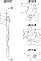
- Fig. 1
- ein erstes Ausführungsbeispiel eines Schraubwerkzeuges in einer perspektivischen Darstellung,
- Fig. 2
- eine Seitenansicht des Schraubwerkzeuges,
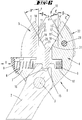
- Fig. 3
- vergrößert, eine Draufsicht auf
das Maul 10 desKopfes 1 des Schraubwerkzeuges, beidem ein Kopfanschlag 23 eine Außerwirkstellung einnimmt, - Fig. 4
- eine
Darstellung gemäß Figur 3 , wobei der Kopfanschlag 23 seine Wirkstellung einnimmt, - Fig. 5
- den Schnitt gemäß der Linie V-V in
Figur 4 - Fig. 6
- den Schnitt gemäß Linie VI-VI in
Figur 2Backen - Fig. 7
- eine
Darstellung gemäß Figur 6 , wobei die beidenBacken - Fig. 8
- eine
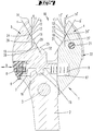
Darstellung gemäß Figur 6 , jedoch mit einervon den Backen einen Sechskantabschnitt 30 ausbildet, wobei das Schraubwerkzeug eine nicht radial gefesselte Drehmoment-Übertragungsstellung einnimmt, - Fig. 9
- eine
Folgedarstellung zu Figur 8 , nach einer Drehung des Kopfes 1 gegenüberdem Sechskantabschnitt 30 im Gegenuhrzeigersinn, wobei sich die beidenBacken entlang von Anlageflächen 11,11' gleiten, - Fig. 10
- eine
Folgedarstellung zu Figur 9 , in der das Schraubwerkzeug in einer radial gefesselten Drehmoment-Übertragungsstellung am Sechskantabschnitt 30 angreift, - Fig. 11
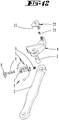
- eine erste Explosionsdarstellung des Schraubwerkzeuges,
- Fig. 12
- eine zweite Explosionsdarstellung des Schraubwerkzeuges und
- Fig. 13
- den Backenbereich eines zweiten Ausführungsbeispiels eines Schraubwerkzeuges.
- Fig. 1
- A first embodiment of a screwing tool in a perspective view,
- Fig. 2
- a side view of the screwing tool,
- Fig. 3
- enlarged, a plan view of the
mouth 10 of thehead 1 of the screwing tool, in which ahead stop 23 occupies a Nichtwirkstellung, - Fig. 4
- a representation according to
FIG. 3 , wherein thehead stop 23 assumes its operative position, - Fig. 5
- the section along the line VV in
FIG. 4 to illustrate the effect of thehead stop 23, - Fig. 6
- the section according to line VI-VI in
FIG. 2 in a first operating position, in which the twojaws - Fig. 7
- a representation according to
FIG. 6 wherein the twojaws - Fig. 8
- a representation according to
FIG. 6 but with a nut held by thejaws hexagonal portion 30, the screwing tool assuming a non-radially constrained torque transmission position, - Fig. 9
- a follow-up presentation to
FIG. 8 after a rotation of thehead 1 with respect to thehexagonal portion 30 in the counterclockwise direction, wherein the twojaws hexagonal section 30 slide along contact surfaces 11, 11 ', - Fig. 10
- a follow-up presentation to
FIG. 9 in which the screwing tool acts on thehexagonal section 30 in a radially constrained torque transmission position, - Fig. 11
- a first exploded view of the screwing tool,
- Fig. 12
- a second exploded view of the screwing and
- Fig. 13
- the jaw region of a second embodiment of a screwing tool.
Die in den Zeichnungen dargestellten Schraubwerkzeuge sind in der Lage, Schrauben mit einem Sechskantkopf bzw. Sechskantmuttern unterschiedlicher Schlüsselweite in einer Schraubrichtung zu drehen. Wird das Schraubwerkzeug entgegen der Schraubrichtung in eine Freilaufrichtung gedreht, so überlaufen die profilierten Backen 4, 5 des Maules 10 die Sechskantecken, um an einer anderen Position des Sechskantabschnitts angesetzt werden zu können. Während beim Stand der Technik das Schraubwerkzeug um mindestens 60° in Freilaufrichtung zurückgedreht werden muss, damit die Backen 4, 5 erneut in einen fesselnden Angriff an das Sechskantprofil treten können, reicht bei dem erfindungsgemäßen Schraubwerkzeug eine Schwenkbewegung in Freilaufrichtung um 30° aus. Dies ist deshalb möglich, weil das Schraubwerkzeug in zwei voneinander verschiedenen Drehmoment-Übertragungsstellungen am Sechskantabschnitt der Mutter bzw. des Schraubenkopfes angreifen kann, um ein Drehmoment zu übertragen, nämlich in einer ersten Drehmoment-Übertragungsstellung, wie sie die
Das Schraubwerkzeug besteht aus einem länglichen, aus Stahl gefertigten Griff 2, der einen zweiarmigen Hebel ausbildet, der um eine Schwenkachse 3 schwenkbar an einem ebenfalls aus Stahl gefertigten Kopf 1 befestigt ist. Der lange Arm des Griffes 2 kann von der Hand eines Benutzers umfasst werden. Der kurze Arm des Griffes 2 besitzt eine Zahnlücke 16, in die ein Zahn 15 eines gegenüber dem Kopf 1 in einer Richtung V verschieblichen Körpers eingreift.The screwing tool consists of an elongated, made of
Dieser verschiebliche Körper bildet eine verschiebliche Backe 5 aus, die gegenüber einer festen Backe 4, die materialeinheitlich mit dem Kopf 1 verbunden ist, verschoben werden kann, wenn der Griff 2 um die Schwenkachse 3 verschwenkt wird.This displaceable body forms a
Ein Führungsabschnitt der Backe 5 greift formschlüssig in einen Führungskanal des Kopfes 1 ein, so dass die verschiebliche Backe 5 linearverschieblich dem Kopf 1 zugeordnet ist. Es ist eine Federaufnahmekammer 7 vorgesehen, in der eine Wendelgang-Druckfeder 6 einliegt. Die Federaufnahmekammer 7 ist von einem Stopfen 8 verschlossen und erstreckt sich in der Verschieberichtung V. Am Stopfen 8 stützt sich ein Ende des Federelementes 6 ab. Das andere Ende beaufschlagt die verschiebliche Backe 5 in Richtung auf die feste Backe 4.A guide portion of the
Es ist optional ein zweites Federelement 9 vorgesehen, welches dem ersten Federelement 6 entgegenwirkt. Damit ist es möglich, die verschiebliche Backe 5 in einer Zwischenstellung zwischen den beiden in den
Zwischen den beiden Backen 4, 5 erstreckt sich ein Maul 10, welches von Wänden flankiert ist.Between the two
Die Wände des Maules 10 bestehen aus einer Vielzahl von Anlageflächen 11, 11', 12, 12', 13, 13', 18, 19, 25, 29, 31. Jede der beiden Backen 4, 5 besitzt eine erste Anlagefläche 11, 11'. Die Anlagefläche 11 ist ebenso wie die Anlagefläche 11' von einer Eckaussparung 24, 24' unterbrochen in zwei vereinzelte erste Anlageflächen 11 bzw. 11'. Die ersten Anlageflächen 11, 11' verlaufen jeweils entlang einer Bezugsebene a, a'. Diese erste Bezugsebene a, a' erstreckt sich im Wesentlichen, also mit einer Abweichung von +/- 2 Grad quer zur Verschieberichtung V. Die Bezugsebene a, die der verschieblichen Backe zugeordnet ist, verläuft somit im Wesentlichen, d.h. mit einer Abweichung von 0 bis -4 Grad parallel zur Bezugsebene a', die der festen Backe 4 zugeordnet ist. Die beiden Bezugsebenen a, a' bilden ein Bezugsebenenpaar.The walls of the
Die
Wird - bezogen auf die Darstellung gemäß
Die Anlagefläche 18 bildet zusammen mit der Anlagefläche 11' eine Eckaussparung 27 aus. Die Anlagefläche 19 der verschieblichen Backe 5 bildet zusammen mit Anlagefläche 11 eine Eckaussparung 26 aus. In diesen beiden Eckaussparungen liegen Eckbereiche des Sechskantabschnittes 30, wenn die Backen 4, 5 in der nicht radial gefesselten Drehmoment-Übertragungsstellung am Sechskantabschnitt 30 angreifen. Wird auf den Griff 2 ein Drehmoment im Uhrzeigersinn aufgebracht, bewirkt der Zahneingriff, dass die verschiebliche Backe 5 in Richtung auf die feste Backe 4 beaufschlagt wird.The
Wird auf den Griff 2 ein Drehmoment in entgegengesetzter Richtung, also im Gegenuhrzeigersinn aufgebracht, so entfernen sich die beiden Backen 4, 5 voneinander, so dass die Eckbereiche des Sechskantabschnittes 30 an den ersten Anlageflächen 11,11' entlanggleiten können, wenn das Schraubwerkzeug relativ gegenüber dem Sechskantabschnitt 30 im Gegenuhrzeigersinn verschwenkt wird. Eine Zwischenstellung zeigt die
Nach einem Verschwenken von 30° gegenüber der in
Zwei sich diametral gegenüberliegende Eckbereiche des Sechskantabschnittes 30 liegen jetzt jeweils in sich gegenüberliegenden Eckaussparungen 24, 24' ein. Es handelt sich dabei um die Eckaussparungen 24, 24', die die beiden ersten Anlageflächen 11, 11' etwa mittig unterbrechen.Two diametrically opposite corner regions of the
Die beiden Flanken der Eckaussparungen 24, 24' werden von zweiten Anlageflächen 12, 12' und dritten Anlageflächen 13, 13' ausgebildet. Die zweiten Anlageflächen 12, 12' erstrecken sich entlang zweiter Bezugsebenen b, b', die gegenüber der ersten Bezugsebene a, a' um einen Winkel von 30° geneigt sind.The two flanks of the corner recesses 24, 24 'are formed by second contact surfaces 12, 12' and third contact surfaces 13, 13 '. The second contact surfaces 12, 12 'extend along second reference planes b, b', which are inclined relative to the first reference plane a, a 'by an angle of 30 °.
Die dritten Anlageflächen 13,13' erstrecken sich entlang dritter Bezugsebenen c, c', die gegenüber der ersten Bezugsebene a, a' ebenfalls um 30° geneigt sind. Die zweiten Bezugsebenen b, b' bilden ein Bezugsebenenpaar mit parallel zueinander verlaufenden Bezugsebenen. Auch die dritten Bezugsebenen c, c' bilden ein Bezugsebenenpaar mit parallel zueinander verlaufenden Bezugsebenen.The third contact surfaces 13, 13 'extend along third reference planes c, c', which are also inclined by 30 ° with respect to the first reference plane a, a ' are. The second reference planes b, b 'form a reference plane pair with mutually parallel reference planes. The third reference planes c, c 'form a reference plane pair with mutually parallel reference planes.
Die dritten Bezugsebenen c, c' und zweiten Bezugsebenen b, b' schneiden sich in einem Winkel von 60 bzw. 120°. Jede der beiden Backen 4, 4' weist zumindest eine zweite Anlagefläche 2, 2' und zumindest eine dritte Anlagefläche 13, 13' auf, wobei die jeweiligen Bezugsebenen c, c' und b, b' parallel zueinander verlaufen.The third reference planes c, c 'and second reference planes b, b' intersect at an angle of 60 and 120 °, respectively. Each of the two
Die zweite Bezugsebene b' erstreckt sich über eine Anlagefläche 12' und eine Anlagefläche 31, wobei sich zwischen den Anlageflächen 12' und 31 eine weitere Eckaussparung 27 befindet, in der eine Mehrkantecke des Sechskantabschnittes 30 in der in
In der in der
Sämtliche Eckaussparungen 24, 26, 28, 27, 24' besitzen Seitenwände, die von Anlageflächen ausgebildet sind, die in einem Winkel von 120° zusammentreffen.All
Auf der festen Backe 4 befindet sich ein Anschlagschieber 22, der von einer Außerwirkstellung, wie die
Die
Die verschiebliche Backe 5 besitzt ebenfalls eine aus zwei Abschnitten bestehende erste Anlagefläche. Ein maulöffnungsseitiger Abschnitt 11 verläuft fluchtend zu einem maulgrundseitigen Abschnitt 11". Die beiden Abschnitte 11, 11" erstrecken sich in einer Bezugsebene a'. Die Bezugsebene a' verläuft ebenfalls im Wesentlichen quer zur Verschieberichtung V, also mit einer Abweichung von +/- 2 Grad zur Senkrechten.The sliding
Die Bezugsebenen a, a' verlaufen im Wesentlichen parallel zueinander, wobei sie im nicht kraftbeaufschlagten Zustand geringfügig in Maulöffnungsrichtung konvergieren, wobei der Konvergenzwinkel 0 bis 4 Grad beträgt. Die Bezugsebenen a, a' richten sich aber bei der Drehmoment-Beaufschlagung als Folge einer kraftbedingten Verformung in eine echte Parallellage aus, in der die maulgrundseitigen Abschnitte 11", 11''', die sich gegenüberliegen, an sich gegenüberliegenden Flanken einer Sechskantschraube oder einer Sechskantmutter anliegen. Die in Richtung der Maulerstreckung gemessene Länge der maulgrundseitigen Abschnitte 11", 11''' ist größer, als die sich in Maulerstreckungsrichtung gemessene Länge der maulöffnungsseitigen Abschnitte 11, 11'. Die Länge der maulgrundseitigen Abschnitte 11", 11''' ist auch größer, als die in Maulerstreckungsrichtung gemessene Weite der Eckaussparungen 24, 24', also dem Abstand der beiden in einer gemeinsamen Bezugsebene a, a' liegenden Abschnitte 11', 11''' bzw. 11, 11".The reference planes a, a 'are substantially parallel to each other, wherein they converge slightly in the unaugmented state in the mouth opening direction, wherein the convergence angle is 0 to 4 degrees. However, the reference planes a, a 'align themselves in the torque application as a result of a force-induced deformation in a true parallel position, in which the
An die maulgrundseitigen Enden der maulgrundseitigen Abschnitte 11", 11''' verlaufen in Maulgrundrichtung betrachtet weitere Anlageflächen 18,19 in einem Winkel von jeweils 60° gegenüber den ersten Anlageflächen 11, 11', 11", 11''' aufeinander zu. An diesen weiteren Anlageflächen 18,19 können Flankenabschnitte von in der nicht radial gefesselten Drehmoment-Übertragungsstellung gehaltenen Schraubenköpfen oder Muttern anliegen. Die Länge der Anlagefläche 18 entspricht etwa der Länge der untereinander gleich langen maulgrundseitigen Abschnitte 11", 11''' der ersten Anlagefläche.At the maulgrundseitigen ends of the
Es sind Findungsschrägen 14, 14' vorgesehen, die sich jeweils an die maulöffnungsseitigen Enden der maulöffnungsseitigen Abschnitte 11,11' der ersten Anlagefläche anschließen. Die Findungsschrägen 14, 14' divergieren voneinander in Maulöffnungsrichtung und erleichtern das Ansetzen des Schraubwerkzeuges auf eine Schraube oder eine Mutter.There are
Das Schraubwerkzeug ist in der Lage, maulschlüsselartig an einem Sechskantprofil anzugreifen, wobei die beiden Backen 4, 5 auf den Schraubenkopf in Radialrichtung, also in Maulerstreckungsrichtung, auf das Sechskantprofil aufgeschoben werden. Dabei beabstanden sich die beiden Backen 4, 5 zueinander, was eine Folge des Auflaufens der Findungsschrägen 14, 14' auf dem Sechskantprofil ist. Das Schraubwerkzeug wird bis in eine Anschlagstellung auf das Sechskantprofil aufgeschoben, indem dessen Flanken an den Anlageflächen 18,19 anliegen. Weitere, parallel zueinander verlaufende Flanken liegen dann an den maulgrundseitigen Abschnitten 11", 11''' der ersten Anlagefläche an, deren Länge bevorzugt der Flankenlänge des Sechskantprofils mit der größten Schlüsselweite entspricht. Wird nach einer Drehung in Schraubrichtung das Schraubwerkzeug um 30° zurückgedreht, so finden die Eckbereiche des Sechskantprofils die Eckaussparungen 24, 24', wobei sich das Sechskantprofil geringfügig in Maulöffnungsrichtung verlagert, bis sich gegenüberliegende Eckbereiche des Sechskantprofiles in den sich gegenüberliegenden Eckaussparungen 24, 24' einliegen. Die Ecken des Sechskantabschnittes können dabei an den Anlageflächen 18,19 entlanggleiten, die somit nicht nur Anlageflächen, sondern auch Gleitflächen ausbilden. Das Sechskantprofil kann dann in dieser radial gefesselten Drehmoment-Übertragungsstellung in Schraubrichtung weitergedreht werden. Bei einer anschließenden Rückverlagerung des Schraubwerkzeuges um 30° gleiten parallel zueinander verlaufende Flanken des Sechskantprofils wieder in eine flächige Anlage zu den ersten Anlageflächen 11,11', wobei sich das Sechskantprofil geringfügig in Radialeinwärtsrichtung bezogen auf die Schwenkachse, also in Richtung auf den Maulgrund, verlagern, bis die Flanken des Sechskantprofiles über ihre gesamte Länge an den maulgrundseitigen Abschnitten 11", 11''' der ersten Anlagefläche anliegen.The screwing tool is able to attack like a wrench on a hexagonal profile, wherein the two
Die vorstehenden Ausführungen dienen der Erläuterung der von der Anmeldung insgesamt erfassten Erfindungen, die den Stand der Technik zumindest durch die folgenden Merkmalskombinationen jeweils auch eigenständig weiterbilden, nämlich:The above explanations serve to explain the total of the application covered inventions, the prior art, at least each independently by the following combinations of characteristics, namely:
Ein Schraubwerkzeug, das dadurch gekennzeichnet ist, dass jede der beiden Backen 4, 5 jeweils zweite 12, 12', 31 und dritte 13, 13', 29 Anlageflächen ausbildet, die jeweils in einer zweiten b, b' und einer dritten c, c' Bezugsebene verlaufen, die jeweils parallel zueinander verlaufen, wobei die zweiten b, b' und dritten c, c' Bezugsebenen bezogen auf die Drehebene jeweils zu den ersten Bezugsebenen a, a' in einem Winkel β, γ von 30° und zueinander in einem Winkel y + β von 60° verlaufen, so dass auf Sechskantabschnitte 30 von Muttern oder Schrauben verschiedener Schlüsselweite in einer ersten Drehmoment-Einbringstellung und in einer dazu um 30° versetzten zweiten Drehmoment-Einbringstellung jeweils von mindestens zwei von den Anlageflächen gebildeten Druckzonen P an verschiedenen Mehrkantflächen der Sechskantabschnitte 30 eine Druckkraft aufbringbar ist.A screwing tool, which is characterized in that each of the two
Ein Schraubwerkzeug, das dadurch gekennzeichnet ist, dass die Eckaussparungen 24, 24' jeweils zwischen einem maulöffnungsseitigen Abschnitt 11, 11' und einem damit fluchtenden maulgrundseitigen Abschnitt 11", 11''' der ersten Anlagefläche 11, 11' liegt, wobei die lichte Weite des Maules 10 der Abstand den beiden maulgrundseitigen Abschnitten 11", 11'''.A screwing tool, which is characterized in that the corner recesses 24, 24 'respectively between a mouth-
Ein Schraubwerkzeug, das dadurch gekennzeichnet ist, dass die maulgrundseitigen Abschnitte 11", 11''' länger sind als die maulöffnungsseitigen Abschnitte 11, 11' der ersten Anlageflächen 11,11', 11", 11'''. A screwing tool, which is characterized in that the
Ein Schraubwerkzeug, das dadurch gekennzeichnet ist, dass die maulgrundseitigen Abschnitte 11", 11''' länger sind als die Weite der Eckaussparungen 24, 24'.A screwing tool, which is characterized in that the
Ein Schraubwerkzeug, das dadurch gekennzeichnet ist, dass die maulgrundseitigen Abschnitte 11", 11''' mindestens zweimal so lang sind wie die Weite der Eckaussparungen 24, 24'.A screwing tool, which is characterized in that the
Ein Schraubwerkzeug, das dadurch gekennzeichnet ist, dass die Maulöffnung Findungsschrägen 14,14' aufweist, die sich in Maulöffnungsrichtung divergierend jeweils an den maulöffnungsseitigen Abschnitt 11, 11' der ersten Anlageflächen 11,11' anschließen.A screwing tool which is characterized in that the mouth opening has finding
Ein Schraubwerkzeug, das dadurch gekennzeichnet ist, dass die ersten, zweiten und dritten sowie weitere Anlageflächen 11, 11'; 12, 12', 13,13', 29; 18, 25, 31 derart angeordnet sind, dass beim Ausüben eines Drehmomentes auf den von den Backen 4, 5 gefassten Sechskantabschnitt 30 auf mindestens drei an verschiedenen Sechskantflächen 20 angreifenden, jeweils von einer Anlagefläche gebildeten Druckzonen P eine Druckkraft auf die Sechskantfläche aufgebracht wird.A screwing tool, which is characterized in that the first, second and third and further contact surfaces 11, 11 '; 12, 12 ', 13, 13', 29; 18, 25, 31 are arranged such that when exerting a torque on the
Ein Schraubwerkzeug, das dadurch gekennzeichnet ist, dass die weiteren Anlageflächen 18, 25, 29 entweder in einer der ersten, zweiten oder dritten Bezugsebene a, a', b, b', c, c' liegen oder in einer weiteren Bezugsebene, die um 30° geneigt gegenüber einer ersten, zweiten oder dritten Bezugsebene verläuft.A screwing tool, which is characterized in that the further contact surfaces 18, 25, 29 either in one of the first, second or third reference plane a, a ', b, b', c, c 'lie or in a further reference plane, the
Ein Schraubwerkzeug, das dadurch gekennzeichnet ist, dass zwischen zwei ersten Anlageflächen 11, 11', zwischen zwei zweiten Anlageflächen 12, 12' und zwischen zwei dritten Anlageflächen 13,13' jeweils eine Eckaussparung 24, 24', 27, 26 liegt, wobei der in der radial nicht gefesselten zweiten Drehmoment-Übertragungsstellung zwei parallel zueinander verlaufende Sechskantflächen an den ersten Anlageflächen 11, 11' anliegen und in der radial gefesselten Drehmoment-Übertragungsstellung zwei sich diametral gegenüberliegende Eckbereiche des Sechskantabschnittes in den Eckaussparungen 24, 24' einliegen.A screwing tool, which is characterized in that between two first contact surfaces 11, 11 ', between two second contact surfaces 12, 12' and between two third contact surfaces 13,13 'each have a
Ein Schraubwerkzeug, das dadurch gekennzeichnet ist, dass die Anlageflächen 11, 11', 12, 12', 31, 13, 13', 29, 18, 25 die Seitenwände eines offenen Maules 10 ausbilden, dessen Maulöffnung Findungsschrägen 14,14' aufweist, die zu den ersten Bezugsebenen a, a' geneigt verlaufen.A screwing tool, which is characterized in that the contact surfaces 11, 11 ', 12, 12', 31, 13, 13 ', 29, 18, 25 form the side walls of an
Ein Schraubwerkzeug, das gekennzeichnet ist durch einen einer der Backen 4 zugeordneten Kopfanschlag 23, der von einer Außerwirkstellung, in der ein von den Backen 4, 5 gefesselter Sechskantabschnitt 30 sich in einer axialen Richtung zwischen den Backen 4, 5 verlagern kann, in eine Wirkstellung bringbar ist, in der der Kopfanschlag 23 die axiale Verlagerbarkeit des Sechskantabschnittes 30 blockiert, indem eine Stirnfläche des Sechskantabschnittes 30 am Kopfanschlag 23 anliegt.A screwing tool, which is characterized by a
Ein Schraubwerkzeug, das gekennzeichnet ist durch ein Federelement 6, mit welchem die verschiebliche Backe 5 in Richtung auf die feste Backe 4 kraftbeaufschlagt wird.A screwing tool, which is characterized by a
Ein Schraubwerkzeug, das dadurch gekennzeichnet ist, dass sich beim Schwenken des Griffs 2 entgegen der Schraubrichtung die an den Sechskantflächen 20 des Sechskantabschnittes 30 anliegenden Anlageflächen 11,11', 12,12', 31,13,13', 29,18, 25 von den Sechskantfläche lösen, so dass sich gegenüberliegende Eckbereiche des Sechskantabschnittes 30 entlang von Anlageflächen gleiten, um die Drehmoment-Übertragungsstellung zu wechseln.A screwing tool which is characterized in that, when the
Ein Schraubwerkzeug, das dadurch gekennzeichnet ist, dass ein der verschieblichen Backe 4 zugeordneter Zahn 15 in eine Zahnlücke 16 eines kurzen Armes des zweiarmigen Griffes 2 eingreift.A screwing tool which is characterized in that a
Ein Schraubwerkzeug, das dadurch gekennzeichnet ist, dass die zwischen den Eckaussparungen 24, 24' und dem von der Öffnung des Maules 10 weisenden Grund des Maules 10 gemessene Länge der ersten Anlageflächen 11", 11''' derart bemessen ist, dass bei einer insbesondere 30 Grad betragenden Hin- und Herbewegung des Schraubwerkzeuges ein zwischen den Backen 4, 5 gefasster Sechskantabschnitt beim Wechseln zwischen einer Flankenanlage des Sechskantabschnitts an den Anlageflächen 11", 11''' und einem Einliegen der Eckbereiche des Sechskantabschnitts in den Eckaussparungen in Erstreckungsrichtung des Maules 10 hin und her wandert.A screwing tool, which is characterized in that between the corner recesses 24, 24 'and that of the opening of the mouth 10th pointing base of the
Alle offenbarten Merkmale sind (für sich, aber auch in Kombination untereinander) erfindungswesentlich. In die Offenbarung der Anmeldung wird hiermit auch der Offenbarungsgehalt der zugehörigen/beigefügten Prioritätsunterlagen (Abschrift der Voranmeldung) vollinhaltlich mit einbezogen, auch zu dem Zweck, Merkmale dieser Unterlagen in Ansprüche vorliegender Anmeldung mit aufzunehmen. Die Unteransprüche charakterisieren mit ihren Merkmalen eigenständige erfinderische Weiterbildungen des Standes der Technik, insbesondere um auf der Basis dieser Ansprüche Teilanmeldungen vorzunehmen. Die in jedem Anspruch angegebene Erfindung kann zusätzlich ein oder mehrere der in der vorstehenden Beschreibung, insbesondere mit Bezugsziffern versehene und/oder in der Bezugsziffernliste angegebene Merkmale aufweisen. Die Erfindung betrifft auch Gestaltungsformen, bei denen einzelne der in der vorstehenden Beschreibung genannten Merkmale nicht verwirklicht sind, insbesondere soweit sie erkennbar für den jeweiligen Verwendungszweck entbehrlich sind oder durch andere technisch gleichwirkenden Mittel ersetzt werden können.
Claims (12)
Applications Claiming Priority (1)
| Application Number | Priority Date | Filing Date | Title |
|---|---|---|---|
| DE102016107025 | 2016-04-15 |
Publications (1)
| Publication Number | Publication Date |
|---|---|
| EP3292957A1 true EP3292957A1 (en) | 2018-03-14 |
Family
ID=58547413
Family Applications (1)
| Application Number | Title | Priority Date | Filing Date |
|---|---|---|---|
| EP17166477.4A Withdrawn EP3292957A1 (en) | 2016-04-15 | 2017-04-13 | Screwing tool with movable jaw |
Country Status (2)
| Country | Link |
|---|---|
| EP (1) | EP3292957A1 (en) |
| DE (1) | DE102017108014A1 (en) |
Cited By (1)
| Publication number | Priority date | Publication date | Assignee | Title |
|---|---|---|---|---|
| CN112236265A (en) * | 2018-06-06 | 2021-01-15 | 维拉工具有限责任公司 | Spanner |
Families Citing this family (2)
| Publication number | Priority date | Publication date | Assignee | Title |
|---|---|---|---|---|
| DE102018113478A1 (en) | 2018-06-06 | 2019-12-12 | Wera Werkzeuge Gmbh | Screwing tool with mutually movable jaws |
| USD967682S1 (en) | 2020-02-27 | 2022-10-25 | Wera Werkzeuge Gmbh | Wrench |
Citations (12)
| Publication number | Priority date | Publication date | Assignee | Title |
|---|---|---|---|---|
| US1048298A (en) | 1912-03-13 | 1912-12-24 | John K Daniels | Wrench. |
| US1506362A (en) * | 1923-03-14 | 1924-08-26 | Alvin O Carman | Wrench |
| DE931580C (en) | 1952-04-27 | 1955-08-11 | Eugen Dr-Ing Mayer | Adjustable wrench |
| DE935418C (en) | 1953-03-04 | 1955-11-17 | Eugen Dr-Ing Mayer | Adjustable wrench |
| US2751802A (en) | 1953-06-30 | 1956-06-26 | Chauncey R Hatch Jr | Box wrench having a pivotally mounted workpiece abutment |
| DE1931580U (en) | 1965-11-06 | 1966-01-27 | Homa G M B H | INSULATING STRIP FOR MECHANICAL MOUNTING AND GUIDING OF ELECTRICAL TRACKS. |
| DE9404031U1 (en) | 1994-03-07 | 1994-05-19 | Lacrex S.A., Orselina | Universal key |
| EP0839611A1 (en) * | 1996-10-30 | 1998-05-06 | Eduard Wille GmbH & Co. | Open-ended wrench |
| DE20007561U1 (en) | 2000-04-27 | 2000-10-05 | Huang, Chia-Hao, Taichung | Adjustable wrench |
| DE10204805A1 (en) * | 2002-02-06 | 2003-08-14 | Markus Feldhaus | Set spanner with free return stroke has gap shaped to enable ratchet effect in reverse direction |
| WO2010069783A2 (en) * | 2008-12-19 | 2010-06-24 | Wera - Werk Hermann Werner Gmbh & Co. Kg | Combination wrench |
| DE112011104952T5 (en) | 2011-02-25 | 2013-12-12 | Jim LAI | wrench |
-
2017
- 2017-04-13 DE DE102017108014.7A patent/DE102017108014A1/en active Pending
- 2017-04-13 EP EP17166477.4A patent/EP3292957A1/en not_active Withdrawn
Patent Citations (12)
| Publication number | Priority date | Publication date | Assignee | Title |
|---|---|---|---|---|
| US1048298A (en) | 1912-03-13 | 1912-12-24 | John K Daniels | Wrench. |
| US1506362A (en) * | 1923-03-14 | 1924-08-26 | Alvin O Carman | Wrench |
| DE931580C (en) | 1952-04-27 | 1955-08-11 | Eugen Dr-Ing Mayer | Adjustable wrench |
| DE935418C (en) | 1953-03-04 | 1955-11-17 | Eugen Dr-Ing Mayer | Adjustable wrench |
| US2751802A (en) | 1953-06-30 | 1956-06-26 | Chauncey R Hatch Jr | Box wrench having a pivotally mounted workpiece abutment |
| DE1931580U (en) | 1965-11-06 | 1966-01-27 | Homa G M B H | INSULATING STRIP FOR MECHANICAL MOUNTING AND GUIDING OF ELECTRICAL TRACKS. |
| DE9404031U1 (en) | 1994-03-07 | 1994-05-19 | Lacrex S.A., Orselina | Universal key |
| EP0839611A1 (en) * | 1996-10-30 | 1998-05-06 | Eduard Wille GmbH & Co. | Open-ended wrench |
| DE20007561U1 (en) | 2000-04-27 | 2000-10-05 | Huang, Chia-Hao, Taichung | Adjustable wrench |
| DE10204805A1 (en) * | 2002-02-06 | 2003-08-14 | Markus Feldhaus | Set spanner with free return stroke has gap shaped to enable ratchet effect in reverse direction |
| WO2010069783A2 (en) * | 2008-12-19 | 2010-06-24 | Wera - Werk Hermann Werner Gmbh & Co. Kg | Combination wrench |
| DE112011104952T5 (en) | 2011-02-25 | 2013-12-12 | Jim LAI | wrench |
Cited By (3)
| Publication number | Priority date | Publication date | Assignee | Title |
|---|---|---|---|---|
| CN112236265A (en) * | 2018-06-06 | 2021-01-15 | 维拉工具有限责任公司 | Spanner |
| CN112236265B (en) * | 2018-06-06 | 2023-08-08 | 维拉工具有限责任公司 | Spanner wrench |
| TWI815901B (en) * | 2018-06-06 | 2023-09-21 | 德商維拉維克催格有限責任公司 | tightening tools |
Also Published As
| Publication number | Publication date |
|---|---|
| DE102017108014A1 (en) | 2017-10-19 |
Similar Documents
| Publication | Publication Date | Title |
|---|---|---|
| EP2376259B1 (en) | Combination wrench | |
| EP1922004B1 (en) | Screwdriver for bone screws | |
| DE202019100356U1 (en) | Torque wrench with an elastic element | |
| DE10011506A1 (en) | Torque transmission tool | |
| EP3292957A1 (en) | Screwing tool with movable jaw | |
| WO1999021685A1 (en) | Open end wrench | |
| DE69314863T2 (en) | Wrench for quick assembly | |
| DE10105653C1 (en) | collet | |
| WO2019219505A1 (en) | Screwing tool for transmitting two set torques | |
| EP3894134B1 (en) | Torque wrench which can be used as a ratchet | |
| WO2013171246A1 (en) | Screwing attachment | |
| DE20108604U1 (en) | Tool wrench with a nut holder | |
| AT17033U1 (en) | screw drive | |
| DE60019140T2 (en) | TURN DRIVE TOOL FOR A SCREW ELEMENT | |
| DE102015205623B4 (en) | Manual wrench | |
| DE102018113478A1 (en) | Screwing tool with mutually movable jaws | |
| DE10236586A1 (en) | Plug-in coupling in two parts, reaction arm, housing, circular axial groove in first coupling part into which fits lug on second coupling part, and locking element | |
| DE102013101361B4 (en) | Edge protection - Ratchet wrench | |
| WO2022090183A1 (en) | Screwdriver insert | |
| EP0111627A1 (en) | Self-locking open-jawed spanner for hexagon head screw pieces of different dimensions | |
| DE3427591A1 (en) | Bolt spanner | |
| EP3741511A1 (en) | Crowbar | |
| WO2013182513A1 (en) | Protective cap for clamping on screw connections | |
| DE20300453U1 (en) | Adjustable pliers for use on hexagonal screw heads, comprising specifically shaped jaw surfaces and recesses for accommodation of larger screws | |
| DE202007008824U1 (en) | Cross connector for profiles |
Legal Events
| Date | Code | Title | Description |
|---|---|---|---|
| PUAI | Public reference made under article 153(3) epc to a published international application that has entered the european phase |
Free format text: ORIGINAL CODE: 0009012 |
|
| AK | Designated contracting states |
Kind code of ref document: A1 Designated state(s): AL AT BE BG CH CY CZ DE DK EE ES FI FR GB GR HR HU IE IS IT LI LT LU LV MC MK MT NL NO PL PT RO RS SE SI SK SM TR |
|
| AX | Request for extension of the european patent |
Extension state: BA ME |
|
| RAP1 | Party data changed (applicant data changed or rights of an application transferred) |
Owner name: WERA WERKZEUGE GMBH |
|
| STAA | Information on the status of an ep patent application or granted ep patent |
Free format text: STATUS: THE APPLICATION IS DEEMED TO BE WITHDRAWN |
|
| 18D | Application deemed to be withdrawn |
Effective date: 20180915 |