EP3292936A1 - Kurzschlussschweissverfahren und vorrichtung zur durchführung eines solchen kurzschlussschweissverfahrens - Google Patents
Kurzschlussschweissverfahren und vorrichtung zur durchführung eines solchen kurzschlussschweissverfahrens Download PDFInfo
- Publication number
- EP3292936A1 EP3292936A1 EP16187971.3A EP16187971A EP3292936A1 EP 3292936 A1 EP3292936 A1 EP 3292936A1 EP 16187971 A EP16187971 A EP 16187971A EP 3292936 A1 EP3292936 A1 EP 3292936A1
- Authority
- EP
- European Patent Office
- Prior art keywords
- short
- welding
- circuit
- phase
- electrode
- Prior art date
- Legal status (The legal status is an assumption and is not a legal conclusion. Google has not performed a legal analysis and makes no representation as to the accuracy of the status listed.)
- Withdrawn
Links
Images

Classifications
-
- B—PERFORMING OPERATIONS; TRANSPORTING
- B23—MACHINE TOOLS; METAL-WORKING NOT OTHERWISE PROVIDED FOR
- B23K—SOLDERING OR UNSOLDERING; WELDING; CLADDING OR PLATING BY SOLDERING OR WELDING; CUTTING BY APPLYING HEAT LOCALLY, e.g. FLAME CUTTING; WORKING BY LASER BEAM
- B23K9/00—Arc welding or cutting
- B23K9/06—Arrangements or circuits for starting the arc, e.g. by generating ignition voltage, or for stabilising the arc
- B23K9/073—Stabilising the arc
- B23K9/0737—Stabilising of the arc position
-
- B—PERFORMING OPERATIONS; TRANSPORTING
- B23—MACHINE TOOLS; METAL-WORKING NOT OTHERWISE PROVIDED FOR
- B23K—SOLDERING OR UNSOLDERING; WELDING; CLADDING OR PLATING BY SOLDERING OR WELDING; CUTTING BY APPLYING HEAT LOCALLY, e.g. FLAME CUTTING; WORKING BY LASER BEAM
- B23K9/00—Arc welding or cutting
- B23K9/09—Arrangements or circuits for arc welding with pulsed current or voltage
- B23K9/091—Arrangements or circuits for arc welding with pulsed current or voltage characterised by the circuits
- B23K9/092—Arrangements or circuits for arc welding with pulsed current or voltage characterised by the circuits characterised by the shape of the pulses produced
-
- B—PERFORMING OPERATIONS; TRANSPORTING
- B23—MACHINE TOOLS; METAL-WORKING NOT OTHERWISE PROVIDED FOR
- B23K—SOLDERING OR UNSOLDERING; WELDING; CLADDING OR PLATING BY SOLDERING OR WELDING; CUTTING BY APPLYING HEAT LOCALLY, e.g. FLAME CUTTING; WORKING BY LASER BEAM
- B23K9/00—Arc welding or cutting
- B23K9/095—Monitoring or automatic control of welding parameters
- B23K9/0953—Monitoring or automatic control of welding parameters using computing means
-
- B—PERFORMING OPERATIONS; TRANSPORTING
- B23—MACHINE TOOLS; METAL-WORKING NOT OTHERWISE PROVIDED FOR
- B23K—SOLDERING OR UNSOLDERING; WELDING; CLADDING OR PLATING BY SOLDERING OR WELDING; CUTTING BY APPLYING HEAT LOCALLY, e.g. FLAME CUTTING; WORKING BY LASER BEAM
- B23K9/00—Arc welding or cutting
- B23K9/10—Other electric circuits therefor; Protective circuits; Remote controls
- B23K9/1006—Power supply
- B23K9/1043—Power supply characterised by the electric circuit
- B23K9/1056—Power supply characterised by the electric circuit by using digital means
-
- B—PERFORMING OPERATIONS; TRANSPORTING
- B23—MACHINE TOOLS; METAL-WORKING NOT OTHERWISE PROVIDED FOR
- B23K—SOLDERING OR UNSOLDERING; WELDING; CLADDING OR PLATING BY SOLDERING OR WELDING; CUTTING BY APPLYING HEAT LOCALLY, e.g. FLAME CUTTING; WORKING BY LASER BEAM
- B23K9/00—Arc welding or cutting
- B23K9/12—Automatic feeding or moving of electrodes or work for spot or seam welding or cutting
- B23K9/124—Circuits or methods for feeding welding wire
Definitions
- the invention relates to a short-circuit welding method with successive welding cycles, each having an arc phase and a short-circuit phase, wherein at least the welding parameters welding current and conveying speed of a consumable electrode of the short-circuit welding process are regulated or adjusted, and the electrode at least during a portion of the arc phase at a predetermined forward end speed in the direction of is conveyed, and at least during a part of the short-circuit phase is conveyed away from the workpiece with a predetermined reminderend york away.
- the invention further relates to an apparatus for carrying out such a short-circuit welding method with successive welding cycles, each having an arc phase and a short-circuit phase, with a device for controlling at least the welding parameters welding current and conveying speed of a consumable electrode, and with a device for conveying the electrode at least during a part of Arc phase up to a predetermined forward end speed towards a workpiece to be machined, and at least during a portion of the short-circuit phase up to a predetermined reminder whatsoever away from the workpiece.
- a short-circuit welding method of the subject type is carried out with a consumable electrode which is conveyed away from the workpiece both in the forward direction to the workpiece and in the backward direction, with a corresponding apparatus and a conveyor for the electrode and a welding torch.
- the welding torch has a conveying device for the electrode and can be used both for manual welding and for automated welding.
- the device for carrying out the short-circuit welding process regulates at least the welding parameters welding current and conveying speed.
- a welding voltage is used in particular to detect a short circuit between the electrode and the workpiece. Likewise, with the welding voltage, the ignition of an arc, so the end of the short circuit detected.
- welding cycles follow each other, in which a period of short circuit and an arc phase alternate periodically.
- the electrode is conveyed back and there is the material transfer, wherein in the arc phase, the electrode is conveyed forward and the arc brings heat into the workpiece or the electrode.
- the object of the present invention is to provide an abovementioned short-circuit welding method, which is characterized by the highest possible stability and high speed and provides sufficient penetration for workpieces with a thickness of up to 3 mm and provides a correspondingly high welding quality.
- a further object is to provide a device for carrying out a short-circuit welding method with which the mentioned advantages can be achieved. Disadvantages of known welding methods or devices should be avoided or at least reduced.
- the object is achieved by a short-circuit welding method in which a change in the conveying speed and a remindineend Norway is set and a welding current is regulated or adjusted, that the short-circuit phase is terminated after reaching the Ruriceend autism and after 3 ms and at the latest every 8 ms is repeated.
- the change in the conveying speed ie the acceleration, results from the desired duration for the short-circuit phase.
- a process of forward and backward movement of the electrode is used for a substantially spatter-free short-circuit welding process. This forward and backward movement results in a welding frequency which specifies a period for a welding cycle consisting of short-circuit phase and arc phase.
- the welding frequency has an influence on the stability of the short-circuit welding process and the welding speed. In order to be able to fulfill both with the highest possible quality, a welding frequency greater than 125 Hz is required so that a new welding cycle begins or the short-circuit phase is repeated every 8ms at the latest. In order to ensure sufficient heat input into the workpiece, in particular as the thickness of the workpiece increases, the arc phase should be as short as possible and the short circuit phase as short as possible.
- a short short-circuit phase has a duration of less than 3 ms, preferably between 2 ms and 3 ms. During the short circuit phase, the direction of advance of the electrode must be reversed from forward movement during the arc phase to backward movement during the short circuit phase.
- the speeds, both forward and backward, depend on the welding application, particularly the material of the workpiece. Typical values are up to 60 m / min for forward and backward movement.
- the reverse end speed is usually lower than the forward end speed, so that the electrode is conveyed on average during the short-circuit welding process in the forward direction to the workpiece.
- the electrode is advanced at a forward end velocity during the arc phase, which substantially corresponds to the reverse end velocity during the short circuit phase. If both velocities are the same and the arc phase is longer than the short-circuit phase, the electrode is also conveyed in the forward direction on average during the short-circuit welding process. The advantage here is that nevertheless a promotion of the electrode results in the direction of the workpiece on average, since the short-circuit phase is much shorter than the arc phase.
- the electrode is conveyed at a forward end speed during the arc phase and a reverse end speed during the short circuit phase in the range between 30 m / min and 60 m / min.
- the forward end speed of the electrode is already reduced before the start of the short-circuit phase. This can be the desired short duration of the short-circuit phase or a high welding frequency can be achieved.
- the welding parameters are preferably controlled such that the duration of a welding cycle is less than or equal to 8 ms, preferably less than or equal to 6.6 ms, resulting in a welding frequency of greater than or equal to 125 Hz, preferably greater than or equal to 150 Hz.
- the welding parameters are controlled such that the duration of the arc phase is at least twice as large as the duration of the short-circuit phase.
- the welding current can be regulated in the form of a current pulse whose duration in the short-circuit phase is determined as a function of the imminent end of the short-circuit phase.
- the welding current during the short-circuit phase initially kept constant over a predetermined period, preferably of at least 1 ms, to a predetermined value and then reduced.
- the change in the conveying speed of the electrode is preferably set in a range between 30000 m / min / s and 60,000 m / min / s, so that the desired times and speeds can be achieved.
- the object according to the invention is also achieved by an abovementioned device for carrying out a short-circuit welding method, wherein the regulating device is designed to reduce the forward end speed of the conveying speed of the electrode and to reverse to the reverse end speed at the latest with the beginning of the short-circuit phase, and thus to increase the conveying speed of the electrode regulate that the short-circuit phase ends at the latest after 3 ms and is repeated at the latest every 8 ms.
- the regulating device is designed to reduce the forward end speed of the conveying speed of the electrode and to reverse to the reverse end speed at the latest with the beginning of the short-circuit phase, and thus to increase the conveying speed of the electrode regulate that the short-circuit phase ends at the latest after 3 ms and is repeated at the latest every 8 ms.
- the means for conveying the electrode formed by a direct drive or a linear drive.
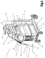
- a device 1 for carrying out a welding process or a welding device for a variety of welding processes is shown.
- the device 1 comprises a power source 2 with a power unit 3 arranged therein, a device 4 for controlling welding parameters P, such as the welding current I or the conveying speed v of a consumable electrode 9 or a welding wire.
- the control device 4 is connected for example to a control valve which is arranged in a supply line for a protective gas 5 between a gas reservoir 6 and a welding torch 7.
- a device 8 for conveying the consumable electrode 9 can be controlled via the control device 4, the electrode 9 being fed from a supply drum 10 into the region of the welding torch 7 via a supply line.
- the conveyor 8 can also in the device 1, in particular in the housing 11 of the power source 2, integrated and not, as in Fig. 1 shown to be positioned on a carriage 12 as an accessory. It is also possible for the conveying device 8 to supply the electrode 9 outside the welding torch 7 to the processing station.
- the welding current I for constructing an arc 13 between the electrode 9 and at least one workpiece 14 is supplied via a welding line (not shown) from the power part 3 of the power source 2, the electrode 9 and formed over the arc 13, a circuit.
- the workpiece 14 is connected to the power source 2 via a further welding line (not shown).
- the welding torch 7 can be connected to a liquid container 16 with a fill level indicator 17 via a cooling device 15 and a cooling of the welding torch 7 can be achieved.
- the device 1, in particular the current source 2, further has an input / output device 18, via which the most varied welding parameters P, operating modes or welding programs can be set or called up and displayed.
- the welding parameters P, operating modes or welding programs set via the input / output device 18 are forwarded to the control device 4 and from this the individual components of the device 1 are subsequently activated or corresponding setpoint values for regulation or control are specified.
- 7 adjustment operations can be made via the welding torch 7 even when using a corresponding welding torch, wherein the welding torch 7 is equipped with a welding torch input / output device 19.
- the welding torch 7 is connected via a data bus to the device 1, in particular the current source 2 or the conveying device 8.
- the welding torch 7 usually has a start switch (not shown), so that the arc 13 can be ignited by actuating the start switch.
- the welding torch 7 is equipped with a heat shield 20.
- the welding torch 7 is connected to the device 1 via a hose package 21.
- the individual lines such as the supply line or lines for the electrode 9, for the protective gas 5, for the cooling circuit, for the data transmission, etc., from the device 1 to the welding torch 7 are arranged.
- the device for conveying the electrode or a motor controller is given a value for the acceleration, ie the change in the conveying speed dv / dt, so that at a time t2 the desired rear end speed v Re is reached.
- Fig. 2 is an acceleration of 40000m / min / s (667m / s 2 ) required, which is given to a motor controller of the conveyor, which controls the conveying speed v accordingly.
- the motor controller thus ensures that the rearward end speed v Re is reached at the time t2 in the short-circuit phase KS.
- the acceleration is set to zero and the conveying speed v is maintained, reduced or increased until the short circuit is broken and the arc is ignited.
- a welding characteristic is made according to the requirements of a welding application and is mainly dependent on material (Al, CrNi, steel, ...), the thickness of the workpiece and the welding speed.
- the acceleration of the delivery of the electrode is specified, among other things, as the backward end speed v Re, via the respective welding characteristic curve.
- the consumable electrode is in the molten bath and the droplet is transferred from the end of the electrode into the molten bath.
- the welding current I is regulated or set in the form of a current pulse during the short-circuit phase KS. In this case, the welding current I is regulated or adjusted such that the droplet is not detached during the current pulse, so that no spatters occur.
- the amplitude and the course of the welding current I is adapted to the required energy during the short duration of the short-circuit phase KS - on the one hand for the maintenance of the temperature of the electrode and on the other hand in preparation for the droplet detachment.
- the value is chosen essentially as a function of the material of the workpiece.
- an amplitude of the welding current I of 120 A is kept constant until the end of the short-circuit phase KS imminent - for example, over 1 ms.
- the current pulse is terminated shortly before the impending end of the short-circuit phase KS or the amplitude of the welding current I is reduced to a maximum of 100 A, for example 50A. Accordingly, the duration of the current pulse is regulated or adjusted.
- the droplet detachment takes place subsequently to this phase - ie after the current pulse - and is essentially spatter-free.
- the current pulse is regulated or adjusted is essentially defined or specified with the welding characteristic.
- the welding current I (amplitude and duration) is regulated either as a function of at least one event, or a fixed value is predetermined for the amplitude and duration of the welding current.
- the time when the amplitude of the welding current I has reached the reduced value, does not necessarily have from the time depend on t2. According to Fig. 2 these times are essentially identical, but independent of each other. Of course, this can also be specified in the welding characteristic that they are interdependent.
- the imminent end of the short-circuit phase KS is determined essentially on the basis of the change in the welding voltage U, as can be seen at the time t3.
- the imminent end of the short-circuit phase KS can also be determined in such a way that at the beginning of the short-circuit phase KS a resistance is calculated from the current welding voltage U and the current welding current I and stored.
- a current resistance can be constantly determined. If the current resistance is higher than the stored resistance by a defined factor, the ignition of the arc and the beginning of the arc phase LB are imminent and the welding current I is reduced. But it can also be a constant comparison of the current resistance with the previously determined resistance and a change or slope are evaluated. If the change is essentially erratic, the ignition of the arc is imminent.
- the arc is ignited at time t3 as soon as the electrode emerges from the molten bath. After the drop has already been detached and the welding current I has already been reduced, this is done without spatter.
- the time t3 of the ignition of the arc varies slightly due to the vibrations of the molten bath.
- the immersion depth of the electrode into the molten bath during the forward feed towards the workpiece and the temperature of the electrode also have an influence.
- this has essentially no influence, since the amplitude and duration of the current pulse is regulated as a function of the upcoming end of the short-circuit phase KS.
- the temperature of the molten bath is maintained.
- the conveying direction of the electrode is again reversed or reversed and accelerated to the value of the forward end speed v Ve , for example to 50 m / min with an acceleration of 40000 m / min / s, essentially the same as the acceleration to the rearward end velocity v Re .
- the welding current I is increased, then lowered to a predetermined value and kept substantially constant and lowered upon reaching the forward speed v Ve of the electrode until the end of the arc phase LB.
- the mean conveying speed v of the electrode which in total represents a conveyance of the electrode towards the workpiece, can be kept substantially constant.
- the stability of the short-circuit welding process can thereby be increased.
- the backward end speed v Re must be reached during the short-circuit phase KS, so that the same arc length, ie the same distance to the workpiece, is always set during the subsequent ignition of the arc.
- a corresponding amplitude for the welding current I during the short-circuit phase KS is specified for the respective welding application. If the amplitude of the welding current I is chosen too high, the Melt electrode over the surface of the molten bath and it would ignite an unwanted arc. If the amplitude of the welding current I is too low, the electrode could be insufficiently preheated and follow a bad ignition.
- the conveying speed v of the electrode in both the forward direction and in the backward direction is relatively high, preferably greater than 30 m / min.
- the short circuit occurs faster.
- the reversal of the direction of conveyance should also be rapid, so that the duration of the short-circuit phase KS is not significantly extended.
- the arc is ignited as quickly as possible and the arc phase LB begins, so that the maximum duration of the short-circuit phase KS of 3 ms is not exceeded.
- the duration of the arc phase LB defines the desired heat input into the workpiece, which can be correspondingly increased by shortening the short-circuit phase KS.
- the arc phase LB is twice as long as the short-circuit phase KS.
- the short-circuit welding method according to the invention can also be used for workpiece thicknesses of up to 3 mm, whereby the required penetration through the longer arc phase LB is ensured.
- the welding application eg fillet weld, butt weld, etc.
- workpieces with a thickness of 2 mm are welded at a welding speed of 1 m / min or workpieces with a thickness of 0.8 mm are welded at a welding speed of 2 m / min.
Landscapes
- Engineering & Computer Science (AREA)
- Physics & Mathematics (AREA)
- Plasma & Fusion (AREA)
- Mechanical Engineering (AREA)
- Theoretical Computer Science (AREA)
- Arc Welding Control (AREA)
Priority Applications (8)
| Application Number | Priority Date | Filing Date | Title |
|---|---|---|---|
| EP16187971.3A EP3292936A1 (de) | 2016-09-09 | 2016-09-09 | Kurzschlussschweissverfahren und vorrichtung zur durchführung eines solchen kurzschlussschweissverfahrens |
| KR1020197010029A KR102015057B1 (ko) | 2016-09-09 | 2017-09-08 | 단락 용접 방법 및 그러한 단락 용접 방법을 수행하기 위한 디바이스 |
| CN201780053195.8A CN109641298B (zh) | 2016-09-09 | 2017-09-08 | 短路焊接方法和执行这种短路焊接方法的装置 |
| US16/331,645 US10661371B2 (en) | 2016-09-09 | 2017-09-08 | Short circuit welding method |
| JP2019513365A JP6683891B2 (ja) | 2016-09-09 | 2017-09-08 | 短絡溶接方法およびこうした短絡溶接方法を実行するための装置 |
| PCT/EP2017/072535 WO2018046633A1 (de) | 2016-09-09 | 2017-09-08 | KURZSCHLUSSSCHWEIßVERFAHREN UND VORRICHTUNG ZUR DURCHFÜHRUNG EINES SOLCHEN KURZSCHLUSSSCHWEIßVERFAHRENS |
| EP17762140.6A EP3509784B2 (de) | 2016-09-09 | 2017-09-08 | Kurzschlussschweissverfahren |
| MX2019002051A MX2019002051A (es) | 2016-09-09 | 2017-09-08 | Metodo de soldadura en corto circuito y dispositivo para llevar a cabo este tipo de metodo de soldadura en corto circuito. |
Applications Claiming Priority (1)
| Application Number | Priority Date | Filing Date | Title |
|---|---|---|---|
| EP16187971.3A EP3292936A1 (de) | 2016-09-09 | 2016-09-09 | Kurzschlussschweissverfahren und vorrichtung zur durchführung eines solchen kurzschlussschweissverfahrens |
Publications (1)
| Publication Number | Publication Date |
|---|---|
| EP3292936A1 true EP3292936A1 (de) | 2018-03-14 |
Family
ID=56893838
Family Applications (2)
| Application Number | Title | Priority Date | Filing Date |
|---|---|---|---|
| EP16187971.3A Withdrawn EP3292936A1 (de) | 2016-09-09 | 2016-09-09 | Kurzschlussschweissverfahren und vorrichtung zur durchführung eines solchen kurzschlussschweissverfahrens |
| EP17762140.6A Active EP3509784B2 (de) | 2016-09-09 | 2017-09-08 | Kurzschlussschweissverfahren |
Family Applications After (1)
| Application Number | Title | Priority Date | Filing Date |
|---|---|---|---|
| EP17762140.6A Active EP3509784B2 (de) | 2016-09-09 | 2017-09-08 | Kurzschlussschweissverfahren |
Country Status (7)
| Country | Link |
|---|---|
| US (1) | US10661371B2 (ja) |
| EP (2) | EP3292936A1 (ja) |
| JP (1) | JP6683891B2 (ja) |
| KR (1) | KR102015057B1 (ja) |
| CN (1) | CN109641298B (ja) |
| MX (1) | MX2019002051A (ja) |
| WO (1) | WO2018046633A1 (ja) |
Cited By (2)
| Publication number | Priority date | Publication date | Assignee | Title |
|---|---|---|---|---|
| CN111037067A (zh) * | 2019-12-30 | 2020-04-21 | 唐山松下产业机器有限公司 | 熔化极短路焊接控制方法 |
| EP4119274A1 (de) | 2021-07-13 | 2023-01-18 | FRONIUS INTERNATIONAL GmbH | Kurzschlussschweissverfahren und schweissvorrichtung |
Families Citing this family (5)
| Publication number | Priority date | Publication date | Assignee | Title |
|---|---|---|---|---|
| JP6876285B2 (ja) * | 2017-05-30 | 2021-05-26 | 一般社団法人発電機協会 | 電源システム |
| DE102019201107B3 (de) | 2019-01-29 | 2020-07-23 | Fronius International Gmbh | Schweißverfahren und Schweißvorrichtung zur Durchführung des Schweißverfahrens |
| EP3815828A1 (de) * | 2019-11-04 | 2021-05-05 | FRONIUS INTERNATIONAL GmbH | Verfahren und vorrichtung zum schweissen einer schweissnaht |
| EP3822014A1 (de) * | 2019-11-18 | 2021-05-19 | FRONIUS INTERNATIONAL GmbH | Verfahren zum abtasten der oberfläche metallischer werkstücke |
| EP4079436A1 (de) * | 2021-04-19 | 2022-10-26 | FRONIUS INTERNATIONAL GmbH | Verfahren zum steuern oder regeln der vorschubgeschwindigkeit eines drahts aus abschmelzendem material bei einem laserlöt- oder laserschweissverfahren sowie laserlöt- oder laserschweissvorrichtung zur durchführung eines solchen verfahrens |
Citations (4)
| Publication number | Priority date | Publication date | Assignee | Title |
|---|---|---|---|---|
| US20050189335A1 (en) * | 2002-07-23 | 2005-09-01 | Gerd Huismann | Method and apparatus for feeding wire to a welding arc |
| US20060138115A1 (en) * | 2002-06-03 | 2006-06-29 | John Norrish | Control method and system for metal arc welding |
| WO2006089322A1 (de) | 2005-02-25 | 2006-08-31 | Fronius International Gmbh | Verfahren zum steuern und/oder regeln eines schweissgerätes und schweissgerät |
| KR20160105769A (ko) * | 2014-01-10 | 2016-09-07 | 가부시키가이샤 다이헨 | 아크 용접 제어 방법 |
Family Cites Families (2)
| Publication number | Priority date | Publication date | Assignee | Title |
|---|---|---|---|---|
| US6160241A (en) * | 1999-03-16 | 2000-12-12 | Lincoln Global, Inc. | Method and apparatus for electric arc welding |
| JP2016144820A (ja) | 2015-02-09 | 2016-08-12 | 株式会社ダイヘン | アーク溶接制御方法 |
-
2016
- 2016-09-09 EP EP16187971.3A patent/EP3292936A1/de not_active Withdrawn
-
2017
- 2017-09-08 EP EP17762140.6A patent/EP3509784B2/de active Active
- 2017-09-08 WO PCT/EP2017/072535 patent/WO2018046633A1/de active Search and Examination
- 2017-09-08 MX MX2019002051A patent/MX2019002051A/es active IP Right Grant
- 2017-09-08 CN CN201780053195.8A patent/CN109641298B/zh active Active
- 2017-09-08 US US16/331,645 patent/US10661371B2/en active Active
- 2017-09-08 KR KR1020197010029A patent/KR102015057B1/ko active IP Right Grant
- 2017-09-08 JP JP2019513365A patent/JP6683891B2/ja active Active
Patent Citations (4)
| Publication number | Priority date | Publication date | Assignee | Title |
|---|---|---|---|---|
| US20060138115A1 (en) * | 2002-06-03 | 2006-06-29 | John Norrish | Control method and system for metal arc welding |
| US20050189335A1 (en) * | 2002-07-23 | 2005-09-01 | Gerd Huismann | Method and apparatus for feeding wire to a welding arc |
| WO2006089322A1 (de) | 2005-02-25 | 2006-08-31 | Fronius International Gmbh | Verfahren zum steuern und/oder regeln eines schweissgerätes und schweissgerät |
| KR20160105769A (ko) * | 2014-01-10 | 2016-09-07 | 가부시키가이샤 다이헨 | 아크 용접 제어 방법 |
Cited By (4)
| Publication number | Priority date | Publication date | Assignee | Title |
|---|---|---|---|---|
| CN111037067A (zh) * | 2019-12-30 | 2020-04-21 | 唐山松下产业机器有限公司 | 熔化极短路焊接控制方法 |
| EP4119274A1 (de) | 2021-07-13 | 2023-01-18 | FRONIUS INTERNATIONAL GmbH | Kurzschlussschweissverfahren und schweissvorrichtung |
| WO2023285416A1 (de) | 2021-07-13 | 2023-01-19 | Fronius International Gmbh | KURZSCHLUSSSCHWEIßVERFAHREN UND SCHWEIßVORRICHTUNG |
| US11992904B1 (en) | 2021-07-13 | 2024-05-28 | Fronius International Gmbh | Short-circuit welding method and welding device |
Also Published As
| Publication number | Publication date |
|---|---|
| WO2018046633A1 (de) | 2018-03-15 |
| US10661371B2 (en) | 2020-05-26 |
| JP2019526453A (ja) | 2019-09-19 |
| EP3509784A1 (de) | 2019-07-17 |
| MX2019002051A (es) | 2019-07-08 |
| KR102015057B1 (ko) | 2019-08-27 |
| CN109641298B (zh) | 2020-04-10 |
| EP3509784B2 (de) | 2023-11-29 |
| EP3509784B1 (de) | 2020-04-22 |
| KR20190040363A (ko) | 2019-04-17 |
| JP6683891B2 (ja) | 2020-04-22 |
| US20190240758A1 (en) | 2019-08-08 |
| CN109641298A (zh) | 2019-04-16 |
Similar Documents
| Publication | Publication Date | Title |
|---|---|---|
| EP3509784B1 (de) | Kurzschlussschweissverfahren und vorrichtung zur durchführung eines solchen kurzschlussschweissverfahrens | |
| EP2442938B1 (de) | Verfahren zum wechseln eines schweissprozesses während eines schweissverfahrens und verfahren zur wärmeeinbringung vor einem schweissverfahren | |
| EP1677940B1 (de) | Verfahren zum steuern und/oder regeln eines schweissprozesses und schweissgerät zur durchführung eines schweissprozesses | |
| EP1850998B1 (de) | Verfahren zum steuern und/oder regeln eines schweissgerätes und schweissgerät | |
| DE202016000598U1 (de) | Schweissbeendigungssystem | |
| AT409832B (de) | Schweissverfahren und schweissgerät zur durchführung des schweissverfahrens | |
| DE102015210741A1 (de) | Brenner für ein Schweißgerät | |
| DE2825283A1 (de) | Verfahren und vorrichtung zum aufbringen von geschmolzenem fuellmaterial | |
| EP3383568B1 (de) | Verfahren zum generativen herstellen von bauteilen mit heizbarer bauplattform und anlage für dieses verfahren | |
| EP2007542A1 (de) | Verfahren zum schweissen eines werkstücks | |
| DE112013003613T5 (de) | Verfahren und ein System zum Starten und Stoppen eines Warmdrahtsystems | |
| EP2359974B1 (de) | Lichtbogen-Schweißverfahren und Schweißstromquelle zur Durchführung des Verfahrens | |
| DE1032863B (de) | Verfahren und Vorrichtung zum Lichtbogenschweissen mit mehreren Elektroden | |
| DE69310054T2 (de) | Schweissverfahren und Schweissroboter | |
| DE19738785A1 (de) | Elektronische Schweißenergiequelle | |
| EP4054784B1 (de) | Verfahren und vorrichtung zum schweissen einer schweissnaht | |
| DE4207902A1 (de) | Automatische lichtbogen-schweissvorrichtung | |
| EP2269758B1 (de) | Gleichstromlichtbogenschweissverfahren | |
| DE3731180C2 (de) | Verfahren und vorrichtung zum spritzerfreien zuenden des schweisslichtbogens beim teil- oder vollmechanischen schweissen mit abschmelzender elektrode | |
| EP3623095A1 (de) | Schweissgerät und schweissverfahren mit selbsteinstellender schweissdrahtvorschubgeschwindigkeit | |
| EP2272615B1 (de) | Konditionierung einer abschmelzenden Elektrode für das Lichtbogenschweissen oder Lichtbogenlöten unter Schutzgas | |
| DE69712786T2 (de) | Verfahren und vorrichtung zum schweissen mit einer gepulsten laserstrahlung | |
| EP4119274A1 (de) | Kurzschlussschweissverfahren und schweissvorrichtung | |
| DE602004004630T2 (de) | Schweissqualitätskontrolle | |
| EP3984681A1 (de) | Verfahren zur vorbereitung eines automatisierten schweissverfahrens auf einen schweissprozess und schweissvorrichtung zur durchführung eines automatisierten schweissverfahrens |
Legal Events
| Date | Code | Title | Description |
|---|---|---|---|
| PUAI | Public reference made under article 153(3) epc to a published international application that has entered the european phase |
Free format text: ORIGINAL CODE: 0009012 |
|
| STAA | Information on the status of an ep patent application or granted ep patent |
Free format text: STATUS: THE APPLICATION HAS BEEN PUBLISHED |
|
| AK | Designated contracting states |
Kind code of ref document: A1 Designated state(s): AL AT BE BG CH CY CZ DE DK EE ES FI FR GB GR HR HU IE IS IT LI LT LU LV MC MK MT NL NO PL PT RO RS SE SI SK SM TR |
|
| AX | Request for extension of the european patent |
Extension state: BA ME |
|
| STAA | Information on the status of an ep patent application or granted ep patent |
Free format text: STATUS: THE APPLICATION IS DEEMED TO BE WITHDRAWN |
|
| 18D | Application deemed to be withdrawn |
Effective date: 20180915 |