EP3509784B2 - Kurzschlussschweissverfahren - Google Patents
Kurzschlussschweissverfahren Download PDFInfo
- Publication number
- EP3509784B2 EP3509784B2 EP17762140.6A EP17762140A EP3509784B2 EP 3509784 B2 EP3509784 B2 EP 3509784B2 EP 17762140 A EP17762140 A EP 17762140A EP 3509784 B2 EP3509784 B2 EP 3509784B2
- Authority
- EP
- European Patent Office
- Prior art keywords
- welding
- short circuit
- phase
- short
- electrode
- Prior art date
- Legal status (The legal status is an assumption and is not a legal conclusion. Google has not performed a legal analysis and makes no representation as to the accuracy of the status listed.)
- Active
Links
- 238000003466 welding Methods 0.000 title claims description 165
- 238000000034 method Methods 0.000 title claims description 45
- 230000001105 regulatory effect Effects 0.000 claims description 16
- 238000002844 melting Methods 0.000 claims description 4
- 230000008018 melting Effects 0.000 claims description 4
- 230000001133 acceleration Effects 0.000 description 12
- 239000000155 melt Substances 0.000 description 9
- 239000000463 material Substances 0.000 description 4
- 230000005540 biological transmission Effects 0.000 description 2
- 238000001816 cooling Methods 0.000 description 2
- 230000035515 penetration Effects 0.000 description 2
- 230000001681 protective effect Effects 0.000 description 2
- 229910000831 Steel Inorganic materials 0.000 description 1
- 230000001419 dependent effect Effects 0.000 description 1
- 238000007654 immersion Methods 0.000 description 1
- 239000007788 liquid Substances 0.000 description 1
- 230000010355 oscillation Effects 0.000 description 1
- 238000002360 preparation method Methods 0.000 description 1
- 238000003825 pressing Methods 0.000 description 1
- 230000005855 radiation Effects 0.000 description 1
- 230000009467 reduction Effects 0.000 description 1
- 238000004904 shortening Methods 0.000 description 1
- 239000010959 steel Substances 0.000 description 1
Images

Classifications
-
- B—PERFORMING OPERATIONS; TRANSPORTING
- B23—MACHINE TOOLS; METAL-WORKING NOT OTHERWISE PROVIDED FOR
- B23K—SOLDERING OR UNSOLDERING; WELDING; CLADDING OR PLATING BY SOLDERING OR WELDING; CUTTING BY APPLYING HEAT LOCALLY, e.g. FLAME CUTTING; WORKING BY LASER BEAM
- B23K9/00—Arc welding or cutting
- B23K9/09—Arrangements or circuits for arc welding with pulsed current or voltage
- B23K9/091—Arrangements or circuits for arc welding with pulsed current or voltage characterised by the circuits
- B23K9/092—Arrangements or circuits for arc welding with pulsed current or voltage characterised by the circuits characterised by the shape of the pulses produced
-
- B—PERFORMING OPERATIONS; TRANSPORTING
- B23—MACHINE TOOLS; METAL-WORKING NOT OTHERWISE PROVIDED FOR
- B23K—SOLDERING OR UNSOLDERING; WELDING; CLADDING OR PLATING BY SOLDERING OR WELDING; CUTTING BY APPLYING HEAT LOCALLY, e.g. FLAME CUTTING; WORKING BY LASER BEAM
- B23K9/00—Arc welding or cutting
- B23K9/06—Arrangements or circuits for starting the arc, e.g. by generating ignition voltage, or for stabilising the arc
- B23K9/073—Stabilising the arc
- B23K9/0737—Stabilising of the arc position
-
- B—PERFORMING OPERATIONS; TRANSPORTING
- B23—MACHINE TOOLS; METAL-WORKING NOT OTHERWISE PROVIDED FOR
- B23K—SOLDERING OR UNSOLDERING; WELDING; CLADDING OR PLATING BY SOLDERING OR WELDING; CUTTING BY APPLYING HEAT LOCALLY, e.g. FLAME CUTTING; WORKING BY LASER BEAM
- B23K9/00—Arc welding or cutting
- B23K9/09—Arrangements or circuits for arc welding with pulsed current or voltage
- B23K9/091—Arrangements or circuits for arc welding with pulsed current or voltage characterised by the circuits
-
- B—PERFORMING OPERATIONS; TRANSPORTING
- B23—MACHINE TOOLS; METAL-WORKING NOT OTHERWISE PROVIDED FOR
- B23K—SOLDERING OR UNSOLDERING; WELDING; CLADDING OR PLATING BY SOLDERING OR WELDING; CUTTING BY APPLYING HEAT LOCALLY, e.g. FLAME CUTTING; WORKING BY LASER BEAM
- B23K9/00—Arc welding or cutting
- B23K9/095—Monitoring or automatic control of welding parameters
- B23K9/0953—Monitoring or automatic control of welding parameters using computing means
-
- B—PERFORMING OPERATIONS; TRANSPORTING
- B23—MACHINE TOOLS; METAL-WORKING NOT OTHERWISE PROVIDED FOR
- B23K—SOLDERING OR UNSOLDERING; WELDING; CLADDING OR PLATING BY SOLDERING OR WELDING; CUTTING BY APPLYING HEAT LOCALLY, e.g. FLAME CUTTING; WORKING BY LASER BEAM
- B23K9/00—Arc welding or cutting
- B23K9/10—Other electric circuits therefor; Protective circuits; Remote controls
- B23K9/1006—Power supply
- B23K9/1043—Power supply characterised by the electric circuit
- B23K9/1056—Power supply characterised by the electric circuit by using digital means
-
- B—PERFORMING OPERATIONS; TRANSPORTING
- B23—MACHINE TOOLS; METAL-WORKING NOT OTHERWISE PROVIDED FOR
- B23K—SOLDERING OR UNSOLDERING; WELDING; CLADDING OR PLATING BY SOLDERING OR WELDING; CUTTING BY APPLYING HEAT LOCALLY, e.g. FLAME CUTTING; WORKING BY LASER BEAM
- B23K9/00—Arc welding or cutting
- B23K9/12—Automatic feeding or moving of electrodes or work for spot or seam welding or cutting
- B23K9/124—Circuits or methods for feeding welding wire
Definitions
- the invention relates to a short-circuit welding process with successive welding cycles, each with an arc phase and a short-circuit phase, wherein at least the welding parameters welding current and conveying speed of a consumable electrode of the short-circuit welding process are regulated or adjusted, and the electrode at least during part of the arc phase with a predetermined forward end speed in the direction of The workpiece to be machined is conveyed and is conveyed away from the workpiece at a predetermined reverse end speed at least during part of the short-circuit phase.
- an unclaimed device for carrying out such a short-circuit welding process with successive welding cycles, each with an arc phase and a short-circuit phase, with a device for regulating at least the welding parameters welding current and conveying speed of a consumable electrode, and with a device for conveying the electrode at least during a part the arc phase up to a predetermined forward end speed in the direction of a workpiece to be machined, and at least during a part of the short-circuit phase up to a predetermined reverse end speed away from the workpiece.
- a short-circuit welding process of the present type is carried out with a consumable electrode, which is conveyed both in the forward direction towards the workpiece and in the backward direction away from the workpiece, with a corresponding device and a conveyor device for the electrode and a welding torch.
- the welding torch has a conveyor device for the electrode and can be used for both manual welding and automated welding.
- the device for carrying out the short-circuit welding process regulates at least the welding parameters welding current and conveying speed.
- a welding voltage is used in particular to detect a short circuit between the electrode and the workpiece.
- the welding voltage is also used to detect the ignition of an arc, i.e. the end of the short circuit.
- a short-circuit welding process welding cycles follow one another, in which a short-circuit phase and an arc phase periodically alternate.
- the electrode In the short-circuit phase, the electrode is conveyed back and the material transfer takes place, whereas in the arc phase the electrode is conveyed forward and the arc introduces heat into the workpiece or the electrode.
- the KR 20160105769 A describes an arc welding process in which the welding current and the conveying speed of the melting welding wire are regulated accordingly, with the arc phase being essentially the same length as the short-circuit phase.
- the object of the present invention is to create a short-circuit welding process mentioned above, which is characterized by the highest possible stability and high speed and offers sufficient penetration for workpieces with a thickness of up to 3 mm and offers a correspondingly high welding quality. Disadvantages of known welding methods or devices should be avoided or at least reduced.
- the task is solved by a short-circuit welding process in which a change in the conveying speed and a reverse end speed is specified and a welding current is regulated or adjusted so that the short-circuit phase is ended after reaching the reverse end speed and after 3 ms at the latest and is repeated every 8 ms at the latest, wherein the forward end speed of the electrode is reduced before the start of the short-circuit phase, and the welding parameters are regulated such that the duration of a welding cycle is less than or equal to 8 ms, resulting in a welding frequency of greater than or equal to 125 Hz (see claim 1).
- the change in conveying speed i.e. the acceleration, results from the desired duration for the short-circuit phase.
- a process with a back and forth movement of the electrode is used.
- This back and forth movement results in a welding frequency that specifies a period for a welding cycle consisting of a short-circuit phase and an arc phase.
- the welding frequency has an influence on the stability of the short-circuit welding process and the welding speed.
- a welding frequency greater than 125 Hz is required, so that a new welding cycle begins or the short-circuit phase is repeated every 8 ms at the latest.
- the arc phase should be as long as possible and the short-circuit phase should be as short as possible.
- a short short-circuit phase has a duration of less than 3 ms, preferably between 2 ms and 3 ms.
- the conveying direction of the electrode must be reversed from the forward movement during the arc phase to a backward movement during the short-circuit phase. Because the forward end speed of the electrode is reduced before the start of the short-circuit phase, the desired short duration of the short-circuit phase or a high welding frequency can be achieved.
- the speeds for both forward and reverse movement depend on the welding application, particularly the material of the workpiece. Typical values are up to 60 m/min for forward and backward movement.
- the reverse end speed is usually lower than the forward end speed, so that on average the electrode is conveyed in the forward direction to the workpiece during the short-circuit welding process.
- the electrode is conveyed at a forward end speed during the arc phase, which essentially corresponds to the reverse end speed during the short-circuit phase. If both speeds are the same and the arc phase is longer than the short-circuit phase, the electrode is also conveyed in the forward direction on average during the short-circuit welding process.
- the advantage here is that, on average, the electrode is conveyed towards the workpiece, since the short-circuit phase is significantly shorter than the arc phase.
- the electrode is conveyed with a forward end speed during the arc phase and a reverse end speed during the short-circuit phase in the range between 30 m/min and 60 m/min.
- the welding parameters are preferably regulated in such a way that the duration of a welding cycle is less than or equal to 6.6 ms, resulting in a welding frequency of greater than or equal to 150 Hz.
- the welding parameters are preferably regulated in such a way that the duration of the arc phase is at least twice as long as the duration of the short-circuit phase.
- the welding current can be regulated in the form of a current pulse, the duration of which is determined in the short-circuit phase depending on the impending end of the short-circuit phase.
- the welding current during the short-circuit phase is initially kept constant at a predetermined value for a predetermined period, preferably 1 ms, and then reduced.
- the change in the conveying speed of the electrode is preferably specified in a range between 30,000 m/min/s and 60,000 m/min/s so that the desired times and speeds can be achieved.
- control device for carrying out a short-circuit welding process, wherein the control device is designed to reduce the forward end speed of the conveying speed of the electrode before the start of the short-circuit phase and to reverse it up to the reverse end speed, and to regulate the conveying speed of the electrode in this way that the short-circuit phase ends after 3 ms at the latest and is repeated every 8 ms at the latest, resulting in a welding frequency of greater than or equal to 125 Hz.
- the short-circuit welding process for the advantages that can be achieved in this way.
- the device for conveying the electrode is preferably formed by a direct drive or a linear drive.
- Fig. 1 an unclaimed device 1 for carrying out a welding method according to the invention or an unclaimed welding device for a wide variety of welding processes is shown.
- the device 1 comprises a power source 2 with a power section 3 arranged therein, a device 4 for regulating welding parameters P, such as the welding current I or the conveying speed v of a consumable electrode 9 or a welding wire.
- the control device 4 is connected, for example, to a control valve which is arranged in a supply line for a protective gas 5 between a gas reservoir 6 and a welding torch 7.
- a device 8 for conveying the melting electrode 9 can be controlled via the control device 4, the electrode 9 being fed from a supply drum 10 into the area of the welding torch 7 via a supply line.
- the conveyor device 8 can also be integrated in the device 1, in particular in the housing 11 of the power source 2, and not, as in Fig. 1 shown, be positioned as an additional device on a trolley 12. It is also possible for the conveying device 8 to feed the electrode 9 outside the welding torch 7 to the process location.
- the welding current I for building an arc 13 between the electrode 9 and at least one workpiece 14 is transmitted via a welding line (not shown) from the power section 3 of the power source 2, the electrode 9 and a circuit is formed via the arc 13.
- the workpiece 14 is connected to the power source 2 via a further welding line (not shown).
- the welding torch 7 can be connected to a liquid container 16 with a fill level indicator 17 via a cooling device 15 and the welding torch 7 can be cooled.
- the device 1, in particular the power source 2 also has an input/output device 18, via which the most diverse welding parameters P, operating modes or welding programs can be set or called up and displayed.
- the welding parameters P, operating modes or welding programs set via the input/output device 18 are forwarded to the control device 4 and this then controls the individual components of the device 1 or specifies corresponding target values for the regulation or control. Even when using a corresponding welding torch 7, adjustment processes can be carried out via the welding torch 7, the welding torch 7 being equipped with a welding torch input/output device 19.
- the welding torch 7 is preferably connected to the device 1, in particular the power source 2 or the conveyor device 8, via a data bus.
- the welding torch 7 usually has a start switch (not shown), so that the arc 13 can be ignited by pressing the start switch.
- the welding torch 7 In order to be protected against the high heat radiation from the arc 13, it is possible for the welding torch 7 to be equipped with a heat protection shield 20.
- the welding torch 7 is connected to the device 1 via a hose package 21.
- the individual lines, such as the supply line or lines for the electrode 9, for the protective gas 5, for the cooling circuit, for data transmission, etc., from the device 1 to the welding torch 7 are arranged in the hose package 21.
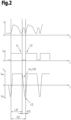
- FIG. 2 An example is in Fig. 2 the time course of the welding current I, the welding voltage U and the conveying speed v of the electrode 9 is shown during a short-circuit welding process.
- the short-circuit welding process is carried out with the following parameters or values: Forward end speed v Ve : 50 m/min Reverse end speed v Re : 40 m/min Welding current I in the short-circuit phase KS: 120 A Duration of the short-circuit phase KS: on average 2.5 ms Welding frequency f: 150 Hz
- the direction of conveyance of the electrode in the short-circuit phase KS is reversed from forward conveyance towards the workpiece with the forward final speed v Ve of 50 m/min to a backward movement away from the workpiece with a reverse final speed v Re of 40 m/min .
- the conveying speed v is already reduced before the short circuit KS, so that the direction reversal can be carried out more quickly and the electrode is immersed less deeply in the melt pool.
- the forward end speed v Ve is reduced after it has been constant for a period of time or after a certain arc burning time. At the latest at time t1 - i.e.
- the device for conveying the electrode or a motor controller is given a value for the acceleration, i.e. the change in the conveying speed dv / dt, so that at a time t2 the desired reverse final speed v Re is achieved.
- an acceleration of 40,000 m/min/s (667 m/s 2 ) is required, which is specified to a motor controller of the conveyor device, which regulates the conveying speed v accordingly.
- the motor controller therefore ensures that the reverse final speed v Re is reached at time t2 in the short-circuit phase KS. Once the reverse final speed v Re is reached, the acceleration is set to zero and the conveying speed v is maintained, reduced or increased until the short circuit is broken and the arc is ignited.
- a welding characteristic curve is created according to the requirements of a welding application and mainly depends on the material (Al, CrNi, steel, ...), the thickness of the workpiece and the welding speed.
- the acceleration of the delivery of the electrode is specified via the respective welding characteristic curve.
- the melting electrode is in the melt pool and the drop is transferred from the end of the electrode into the melt pool.
- the welding current I is regulated or adjusted in the form of a current pulse during the short-circuit phase KS.
- the welding current I is regulated or adjusted in such a way that the drop is not detached during the current pulse, so that no spatter occurs.
- the amplitude and course of the welding current I is adapted to the required energy during the short duration of the short-circuit phase KS - on the one hand to maintain the temperature of the electrode and on the other hand as preparation for drop removal.
- the value is essentially chosen depending on the material of the workpiece. According to Fig.
- an amplitude of the welding current I of 120 A is kept constant until the end of the short-circuit phase KS is imminent - for example over 1 ms.
- the current pulse is only ended shortly before the imminent end of the short-circuit phase KS or the amplitude of the welding current I is reduced to a maximum of 100 A, for example 50 A.
- the duration of the current pulse is regulated or adjusted accordingly.
- the drop release occurs after this phase - i.e. after the current pulse - and is essentially spatter-free.
- the current pulse is regulated or set is essentially defined or specified by the welding characteristic curve.
- the welding current I (amplitude and duration) is either regulated depending on at least one event or a fixed value is specified for the amplitude and duration of the welding current.
- the time at which the amplitude of the welding current I reaches the reduced value does not necessarily have to depend on the time t2. According to Fig. 2 Although these points in time are essentially identical, they are nevertheless independent of one another. Of course, this can also be specified in the welding characteristic curve so that they are dependent on each other.
- the impending end of the short-circuit phase KS is essentially determined based on the change in the welding voltage U, as can be seen at time t3.
- the impending end of the short-circuit phase KS can also be determined in such a way that at the beginning of the short-circuit phase KS a resistance is calculated and stored from the current welding voltage U and the current welding current I.
- a current resistance can constantly be determined. If the current resistance is higher by a defined factor than the stored resistance, the ignition of the arc and the start of the arc phase LB are imminent and the welding current I is reduced. However, a constant comparison of the current resistance with the previously determined resistance can also be carried out and a change or slope can be evaluated. If the change is essentially sudden, ignition of the arc is imminent.
- the acceleration of the delivery of the electrode can also be adjusted in order to achieve the reverse final speed v Re during the short-circuit phase KS.
- the arc is ignited at time t3 as soon as the electrode emerges from the melt pool. After the drop has already been detached and the welding current I has already been reduced, this occurs without weld spatter.
- the time t3 of ignition of the arc varies slightly due to the oscillations of the melt pool.
- the immersion depth of the electrode in the melt pool during forward conveyance towards the workpiece as well as the temperature of the electrode also have an influence. This has essentially no influence on the stability of the welding process, since the amplitude and duration of the current pulse is regulated depending on the impending end of the short-circuit phase KS. This means that the temperature of the melt pool continues to be maintained.
- the conveying direction of the electrode is reversed again or the reversal is initiated and accelerated to the value of the forward final speed v Ve , for example to 50 m/min with an acceleration of 40,000 m/min/s, essentially the same as the acceleration to the final reverse speed v Re .
- the welding current I is increased, then reduced to a predetermined value and kept essentially constant, and when the electrode reaches the final forward speed v Ve , it is reduced to the end of the arc phase LB.
- the average conveying speed v of the electrode which in total represents a conveying of the electrode towards the workpiece, can be kept essentially constant. The stability of the short-circuit welding process can thereby be increased.
- conveyor systems with low mass inertia and a rotor with a maximum diameter of 16.4 mm are required.
- the electrode is preferably driven directly by the conveyor, i.e. without a transmission or gear.
- the reverse final speed v Re must be achieved during the short-circuit phase KS, so that the same arc length, i.e. the same distance to the workpiece, is always achieved when the arc is subsequently ignited.
- a corresponding amplitude for the welding current I during the short-circuit phase KS is specified for the respective welding application. If the amplitude of the welding current I is chosen too high, the electrode could melt above the surface of the melt pool and an unwanted arc would be ignited. If the amplitude of the welding current I is too low, the electrode could be insufficiently preheated and poor ignition could result.
- the conveying speed is also important for a short short-circuit phase KS v of the electrode is relatively high both in the forward direction and in the reverse direction, preferably greater than 30 m/min.
- the short circuit occurs more quickly.
- the reversal of the conveying direction should also take place quickly so that the duration of the short-circuit phase KS is not significantly extended.
- it is important that the arc is ignited as quickly as possible and the arc phase LB begins, so that the maximum duration of the short-circuit phase KS of 3 ms is not exceeded.
- the duration of the arc phase LB defines the desired heat input into the workpiece, which can be increased accordingly by shortening the short-circuit phase KS.
- the arc phase LB is twice as long as the short-circuit phase KS.
- the short-circuit welding method according to the invention therefore ensures that a substantially constant duration is established for the short-circuit phase KS and the arc phase LB based on the respective values of the welding characteristic curve. In addition, this is supported by precise control of the conveying speed v via the acceleration and the control of the welding current I.
- the short-circuit welding method according to the invention can also be used for workpiece thicknesses of up to 3 mm, with the required penetration being guaranteed by the longer arc phase LB.
- workpieces with a thickness of 2 mm can be welded at a welding speed of 1m/min or workpieces with a thickness of 0.8 mm with a Welding speed of 2 m/min can be welded.
Description
- Die Erfindung betrifft ein Kurzschlussschweißverfahren mit aufeinanderfolgenden Schweißzyklen mit jeweils einer Lichtbogenphase und einer Kurzschlussphase, wobei zumindest die Schweißparameter Schweißstrom und Fördergeschwindigkeit einer abschmelzenden Elektrode des Kurzschlussschweißverfahrens geregelt oder eingestellt werden, und die Elektrode zumindest während eines Teils der Lichtbogenphase mit einer vorgegebenen Vorwärtsendgeschwindigkeit in Richtung eines zu bearbeitenden Werkstücks gefördert wird, und zumindest während eines Teils der Kurzschlussphase mit einer vorgegebenen Rückwärtsendgeschwindigkeit vom Werkstück weg gefördert wird.
- Offenbart wird weiters eine nicht beanspruchte Vorrichtung zur Durchführung eines solchen Kurzschlussschweißverfahrens mit aufeinanderfolgenden Schweißzyklen mit jeweils einer Lichtbogenphase und einer Kurzschlussphase, mit einer Einrichtung zur Regelung zumindest der Schweißparameter Schweißstrom und Fördergeschwindigkeit einer abschmelzenden Elektrode, und mit einer Einrichtung zur Förderung der Elektrode zumindest während eines Teils der Lichtbogenphase bis zu einer vorgegebenen Vorwärtsendgeschwindigkeit in Richtung eines zu bearbeitenden Werkstücks, und zumindest während eines Teils der Kurzschlussphase bis zu einer vorgegebenen Rückwärtsendgeschwindigkeit vom Werkstück weg.
- Ein Kurzschlussschweißverfahren der gegenständlichen Art wird mit einer abschmelzenden Elektrode, welche sowohl in Vorwärtsrichtung zum Werkstück als auch in Rückwärtsrichtung vom Werkstück weg gefördert wird, mit einer entsprechenden Vorrichtung und einer Fördereinrichtung für die Elektrode und einem Schweißbrenner durchgeführt. Der Schweißbrenner weist dabei eine Fördereinrichtung für die Elektrode auf und kann sowohl für das manuelle Schweißen als auch für das automatisierte Schweißen verwendet werden. Die Vorrichtung zur Durchführung des Kurzschlussschweißverfahrens regelt dabei zumindest die Schweißparameter Schweißstrom und Fördergeschwindigkeit. Eine Schweißspannung wird insbesondere dazu verwendet, einen Kurzschluss zwischen Elektrode und Werkstück zu erkennen. Ebenso wird mit der Schweißspannung die Zündung eines Lichtbogens, also das Ende des Kurzschlusses, erkannt. Bei einem Kurzschlussschweißverfahren folgen Schweißzyklen aufeinander, in welchen sich eine Kurzschlussphase und eine Lichtbogenphase periodisch abwechseln. In der Kurzschlussphase wird die Elektrode zurück gefördert und es erfolgt der Materialübergang, wobei in der Lichtbogenphase die Elektrode vorwärts gefördert wird und der Lichtbogen Wärme in das Werkstück bzw. die Elektrode einbringt.
- Beispielsweise beschreiben die
US 2006/138115 A1 (Basis des Oberbegriffs der Ansprüche 1 und 10), dieUS 2005/189335 A1 oder dieWO 2006/089322 A1 ein solches Kurzschlussschweißverfahren und eine Vorrichtung zur Durchführung eines Kurzschlussschweißverfahrens. - Die
KR 20160105769 A - Bei bekannten Kurzschlussschweißverfahren treten insbesondere bei höheren Schweißgeschwindigkeiten Instabilitäten auf, welche zu Verringerungen der Schweißqualität führen können. Ein findet sich kein Hinweis auf die Erzielung einer höheren Schweißfrequenz.
- Die Aufgabe der vorliegenden Erfindung besteht darin, ein oben genanntes Kurzschlussschweißverfahren zu schaffen, welches sich durch möglichst hohe Stabilität und hohe Geschwindigkeit auszeichnet und einen ausreichenden Einbrand für Werkstücke mit einer Dicke bis 3 mm bietet und eine entsprechend hohe Schweißqualität bietet. Nachteile bekannter Schweißverfahren oder Vorrichtungen sollen vermieden oder zumindest reduziert werden.
- Die Aufgabe wird durch ein Kurzschlussschweißverfahren gelöst, bei dem eine Änderung der Fördergeschwindigkeit und eine Rückwärtsendgeschwindigkeit vorgegeben wird und ein Schweißstrom ge regelt oder eingestellt wird, dass die Kurzschlussphase nach Erreichen der Rückwärtsendgeschwindigkeit und nach spätestens 3 ms beendet wird und spätestens alle 8 ms wiederholt wird, wobei die Vorwärtsendgeschwindigkeit der Elektrode bereits vor dem Beginn der Kurzschlussphase reduziert wird, und die Schweißparameter derart geregelt werden, dass die Dauer eines Schweißzyklus kleiner oder gleich 8 ms beträgt, resultierend in einer Schweißfrequenz von größer oder gleich 125 Hz (siehe Anspruch 1). Die Änderung der Fördergeschwindigkeit, also die Beschleunigung, ergibt sich aus der gewünschten Dauer für die Kurzschlussphase. Für ein im Wesentlichen spritzerfreies Kurzschlussschweißverfahren wird ein Prozess mit einer Vor- und Rückbewegung der Elektrode verwendet. Aus dieser Vor- und Rückbewegung resultiert eine Schweißfrequenz, die eine Periode für einen aus Kurzschlussphase und Lichtbogenphase bestehenden Schweißzyklus vorgibt. Die Schweißfrequenz hat dabei einen Einfluss auf die Stabilität des Kurzschlussschweißverfahrens und die Schweißgeschwindigkeit. Um beides mit möglichst hoher Qualität erfüllen zu können, ist eine Schweißfrequenz größer 125 Hz erforderlich, sodass spätestens alle 8 ms ein neuer Schweißzyklus beginnt bzw. die Kurzschlussphase wiederholt wird. Um eine ausreichende Wärmeeinbringung in das Werkstück zu gewährleisten, insbesondere bei zunehmender Dicke des Werkstücks, sollte die Lichtbogenphase möglichst lang und die Kurzschlussphase entsprechend möglichst kurz sein. Eine kurze Kurzschlussphase hat dabei eine Dauer von weniger als 3 ms, bevorzugt zwischen 2 ms und 3 ms. Während der Kurzschlussphase muss die Förderrichtung der Elektrode von der Vorwärtsbewegung während der Lichtbogenphase in eine Rückwärtsbewegung während der Kurzschlussphase umgekehrt werden. Dadurch, dass die Vorwärtsendgeschwindigkeit der Elektrode bereits vor dem Beginn der Kurzschlussphase reduziert wird, kann die gewünschte geringe Dauer der Kurzschlussphase bzw. eine hohe Schweißfrequenz erzielt werden. Die Geschwindigkeiten, sowohl für die Vorwärtsbewegung als auch für die Rückwärtsbewegung sind von der Schweißanwendung, insbesondere vom Material des Werkstücks, abhängig. Typische Werte sind bis zu 60 m/min für die Vorwärts- und Rückwärtsbewegung. Die Rückwärtsendgeschwindigkeit ist dabei meist geringer als die Vorwärtsendgeschwindigkeit, sodass die Elektrode im Mittel während des Kurzschlussschweißverfahrens in Vorwärtsrichtung zum Werkstück gefördert wird.
- Vorzugsweise wird die Elektrode mit einer Vorwärtsendgeschwindigkeit während der Lichtbogenphase gefördert, welche im Wesentlichen der Rückwärtsendgeschwindigkeit während der Kurzschlussphase entspricht. Sind beide Geschwindigkeiten gleich und ist die Lichtbogenphase länger als die Kurzschlussphase, wird die Elektrode im Mittel während des Kurzschlussschweißverfahrens ebenfalls in Vorwärtsrichtung gefördert. Vorteilhaft ist hierbei, dass dennoch im Mittel eine Förderung der Elektrode in Richtung Werkstück resultiert, da die Kurzschlussphase wesentlich kürzer als die Lichtbogenphase ist.
- Vorteilhafter Weise wird die Elektrode mit einer Vorwärtsendgeschwindigkeit während der Lichtbogenphase und einer Rückwärtsendgeschwindigkeit während der Kurzschlussphase im Bereich zwischen 30 m/min und 60 m/min gefördert.
- Dabei werden die Schweißparameter vorzugsweise derart geregelt, dass die Dauer eines Schweißzyklus kleiner oder gleich 6,6 ms beträgt, resultierend in einer Schweißfrequenz von größer oder gleich 150 Hz.
- Bevorzugt werden die Schweißparameter derart geregelt werden, dass die Dauer der Lichtbogenphase mindestens doppelt so groß wie die Dauer der Kurzschlussphase ist.
- Der Schweißstrom kann in Form eines Strompulses geregelt werden, dessen Dauer in der Kurzschlussphase in Abhängigkeit vom bevorstehenden Ende der Kurzschlussphase ermittelt wird.
- Für die Schweißqualität ist es von Vorteil, wenn der Schweißstrom während der Kurzschlussphase zunächst über eine vorgegebene Dauer, vorzugsweise von 1 ms, auf einem vorgegebenen Wert konstant gehalten und danach reduziert wird.
- Die Änderung der Fördergeschwindigkeit der Elektrode wird vorzugsweise in einem Bereich zwischen 30000 m/min/s und 60000 m/min/s vorgegeben, sodass die gewünschten Zeiten und Geschwindigkeiten erzielt werden können.
- Offenbart wird auch eine oben erwähnte, nicht beanspruchte Vorrichtung zur Durchführung eines Kurzschlussschweißverfahrens, wobei die Regelungseinrichtung dazu ausgebildet ist, bereits vor dem Beginn der Kurzschlussphase die Vorwärtsendgeschwindigkeit der Fördergeschwindigkeit der Elektrode zu reduzieren und bis zur Rückwärtsendgeschwindigkeit umzukehren, und die Fördergeschwindigkeit der Elektrode so zu regeln, dass die Kurzschlussphase spätestens nach 3 ms beendet ist und und spätestens alle 8 ms wiederholt wird, resultierend in einer Schweißfrequenz von größer oder gleich 125 Hz. Zu den dadurch erzielbaren Vorteilen wird auf die obige Beschreibung des Kurzschlussschweißverfahrens verwiesen.
- Vorzugsweise ist die Einrichtung zur Förderung der Elektrode durch einen Direktantrieb oder einen Linearantrieb gebildet.
- Die vorliegende Erfindung wird anhand der beigefügten Zeichnungen näher erläutert. Darin zeigen:
-
Fig. 1 eine schematische Darstellung einer Schweißmaschine bzw. eines Schweißgerätes; und -
Fig. 2 den zeitlichen Verlauf des Schweißstromes I, der Schweißspannung U und der Fördergeschwindigkeit v der Elektrode während eines erfindungsgemäßen Kurzschlussschweißverfahrens. - In
Fig. 1 ist eine nicht beanspruchte Vorrichtung 1 zur Durchführung eines erfindungsgemäßen Schweißverfahrens bzw. ein nicht beanspruchtes Schweißgerät für verschiedenste Schweißprozesse gezeigt. Die Vorrichtung 1 umfasst eine Stromquelle 2 mit einem darin angeordneten Leistungsteil 3, eine Einrichtung 4 zur Regelung von Schweißparametern P, wie dem Schweißstrom I oder der Fördergeschwindigkeit v einer abschmelzenden Elektrode 9 bzw. eines Schweißdrahts. Die Regeleinrichtung 4 ist beispielsweise mit einem Steuerventil verbunden, welches in einer Versorgungsleitung für ein Schutzgas 5 zwischen einem Gasspeicher 6 und einem Schweißbrenner 7 angeordnet ist. Zudem kann über die Regeleinrichtung 4 noch eine Einrichtung 8 zur Förderung der abschmelzenden Elektrode 9 angesteuert werden, wobei über eine Versorgungsleitung die Elektrode 9 von einer Vorratstrommel 10 in den Bereich des Schweißbrenners 7 zugeführt wird. Die Fördereinrichtung 8 kann auch in der Vorrichtung 1, insbesondere im Gehäuse 11 der Stromquelle 2, integriert und nicht, wie inFig. 1 dargestellt, als Zusatzgerät auf einen Fahrwagen 12 positioniert sein. Es ist auch möglich, dass die Fördereinrichtung 8 die Elektrode 9 außerhalb des Schweißbrenners 7 an die Prozessstelle zuführt. - Der Schweißstrom I zum Aufbauen eines Lichtbogens 13 zwischen der Elektrode 9 und zumindest einem Werkstück 14 wird über eine Schweißleitung (nicht dargestellt) vom Leistungsteil 3 der Stromquelle 2, der Elektrode 9 zugeführt und über den Lichtbogen 13 ein Stromkreis gebildet. Das Werkstück 14 ist über eine weitere Schweißleitung (nicht dargestellt) mit der Stromquelle 2 verbunden.
- Zum Kühlen des Schweißbrenners 7 kann über ein Kühlgerät 15 der Schweißbrenner 7 mit einem Flüssigkeitsbehälter 16 mit einer Füllstandsanzeige 17 verbunden werden und eine Kühlung des Schweißbrenners 7 erzielt werden.
- Die Vorrichtung 1, insbesondere die Stromquelle 2, weist weiters eine Ein-/Ausgabevorrichtung 18 auf, über die die unterschiedlichsten Schweißparameter P, Betriebsarten oder Schweißprogramme eingestellt bzw. aufgerufen und angezeigt werden können. Dabei werden die über die Ein-/Ausgabevorrichtung 18 eingestellten Schweißparameter P, Betriebsarten oder Schweißprogramme an die Regeleinrichtung 4 weitergeleitet und von dieser werden anschließend die einzelnen Komponenten der Vorrichtung 1 angesteuert bzw. entsprechende Sollwerte für die Regelung oder Steuerung vorgegeben. Hierbei können auch bei Verwendung eines entsprechenden Schweißbrenners 7 Einstellvorgänge über den Schweißbrenner 7 vorgenommen werden, wobei der Schweißbrenner 7 mit einer Schweißbrenner-Ein-/Ausgabevorrichtung 19 ausgestattet ist. Bevorzugt ist der Schweißbrenner 7 über einen Datenbus mit der Vorrichtung 1, insbesondere der Stromquelle 2 oder der Fördervorrichtung 8 verbunden.
- Zum Starten des Schweißprozesses weist der Schweißbrenner 7 meist einen Startschalter (nicht dargestellt) auf, sodass durch Betätigen des Startschalters der Lichtbogen 13 gezündet werden kann. Um gegen die große Hitzeeinstrahlung vom Lichtbogen 13 geschützt zu werden, ist es möglich, dass der Schweißbrenner 7 mit einem Hitzeschutzschild 20 ausgestattet wird. Weiters ist in dem dargestellten Ausführungsbeispiel der Schweißbrenner 7 über ein Schlauchpaket 21 mit der Vorrichtung 1 verbunden. Im Schlauchpaket 21 sind die einzelnen Leitungen, wie beispielsweise die Versorgungsleitung bzw. Leitungen für die Elektrode 9, für das Schutzgas 5, für den Kühlkreislauf, für die Datenübertragung, usw., von der Vorrichtung 1 zum Schweißbrenner 7 angeordnet.
- Beispielhaft ist in
Fig. 2 der zeitliche Verlauf des Schweißstromes I, der Schweißspannung U und der Fördergeschwindigkeit v der Elektrode 9 während eines Kurzschlussschweißverfahrens dargestellt. Das Kurzschlussschweißverfahren wird mit den folgenden Parametern bzw. Werten durchgeführt:
Vorwärtsendgeschwindigkeit vVe: 50 m/min Rückwärtsendgeschwindigkeit vRe: 40 m/min Schweißstrom I in der Kurzschlussphase KS: 120 A Dauer der Kurzschlussphase KS: im Mittel 2,5 ms Schweißfrequenz f: 150 Hz - Aus den Zeitverläufen ist ersichtlich, dass die Richtung der Förderung der Elektrode in der Kurzschlussphase KS von der Vorwärtsförderung in Richtung Werkstück mit der Vorwärtsendgeschwindigkeit vVe von 50 m/min auf eine Rückwärtsbewegung vom Werkstück weg mit einer Rückwärtsendgeschwindigkeit vRe von 40m/min umgekehrt wird. Die Fördergeschwindigkeit v wird bereits vor dem Kurzschluss KS reduziert, sodass die Richtungsumkehr schneller durchgeführt werden kann und die Elektrode weniger tief in das Schmelzbad eintaucht. Beispielsweise erfolgt die Reduktion der Vorwärtsendgeschwindigkeit vVe nachdem diese eine Zeitdauer konstant war oder nach einer gewissen Lichtbogenbrenndauer. Spätestens zum Zeitpunkt t1 - also mit Beginn der Kurzschlussphase KS - wird der Einrichtung zur Förderung der Elektrode bzw. einem Motorregler ein Wert für die Beschleunigung, also die Änderung der Fördergeschwindigkeit dv/dt, vorgegeben, sodass zu einem Zeitpunkt t2 die gewünschte Rückwärtsendgeschwindigkeit vRe erreicht wird.
- Beim Beispiel gemäß
Fig. 2 ist dafür eine Beschleunigung von 40000m/min/s (667m/s2) erforderlich, welche einem Motorregler der Fördereinrichtung vorgegeben wird, der die Fördergeschwindigkeit v entsprechend regelt. Der Motorregler gewährleistet also, dass die Rückwärtsendgeschwindigkeit vRe zum Zeitpunkt t2 in der Kurzschlussphase KS erreicht wird. Ist die Rückwärtsendgeschwindigkeit vRe erreicht, wird die Beschleunigung auf null gestellt und die Fördergeschwindigkeit v gehalten, reduziert oder erhöht, bis der Kurzschluss aufgebrochen wird und der Lichtbogen gezündet wird. - Ob und wie die Fördergeschwindigkeit v nach dem Erreichen der Rückwärtsendgeschwindigkeit vRe verändert wird, wird bei der Definition der Schweißkennlinie festgelegt. Eine Schweißkennlinie wird nach den Anforderungen einer Schweißanwendung erstellt und ist hauptsächlich von Material (Al, CrNi, Stahl, ...), der Dicke des Werkstücks und der Schweißgeschwindigkeit abhängig.
- Die Beschleunigung der Förderung der Elektrode wird unter anderem wie die Rückwärtsendgeschwindigkeit vRe über die jeweilige Schweißkennlinie vorgegeben.
- In der Kurzschlussphase KS befindet sich die abschmelzende Elektrode im Schmelzbad und der Tropfen wird vom Ende der Elektrode in das Schmelzbad übergeben. Um sicherzustellen, dass der Tropfen während der Dauer der Kurzschlussphase KS im Schmelzbad abgelöst wird, wird der Schweißstrom I in Form eines Strompulses während der Kurzschlussphase KS geregelt oder eingestellt. Dabei wird der Schweißstrom I derart geregelt oder eingestellt, dass der Tropfen nicht während des Strompulses abgelöst wird, sodass keine Spritzer entstehen. Die Amplitude und der Verlauf des Schweißstromes I wird an die erforderliche Energie während der kurzen Dauer der Kurzschlussphase KS angepasst- zum einen für die Aufrechterhaltung der Temperatur der Elektrode und zum anderen als Vorbereitung für die Tropfenablöse. Der Wert wird im Wesentlichen in Abhängigkeit des Materials des Werkstücks gewählt. Gemäß
Fig. 2 wird eine Amplitude des Schweißstroms I von 120 A so lange konstant gehalten, bis das Ende der Kurzschlussphase KS unmittelbar bevorsteht - beispielsweise über 1 ms. Um Schweißspritzer bei der folgenden Tropfenablöse zu verhindern, wird der Strompuls erst kurz vor dem bevorstehenden Ende der Kurzschlussphase KS beendet bzw. die Amplitude des Schweißstroms I auf maximal 100 A, beispielsweise 50 A reduziert. Dementsprechend wird die Dauer des Strompulses geregelt oder eingestellt. Die Tropfenablöse erfolgt dabei anschließend an diese Phase - also nach dem Strompuls - und ist im Wesentlichen spritzerfrei. - Ob der Strompuls geregelt wird oder eingestellt ist, wird im Wesentlichen mit der Schweißkennlinie definiert bzw. vorgegeben. Der Schweißstrom I (Amplitude und Dauer) wird entweder in Abhängigkeit zumindest eines Ereignisses geregelt oder es wird für die Amplitude und Dauer des Schweißstromes ein fixer Wert vorgegeben. Der Zeitpunkt, wann die Amplitude des Schweißstromes I den reduzierten Wert erreicht hat, muss nicht zwingend vom Zeitpunkt t2 abhängen. Gemäß
Fig. 2 sind diese Zeitpunkte im Wesentlichen zwar identisch, dennoch unabhängig voneinander. Selbstverständlich kann dies auch so in der Schweißkennlinie vorgegeben werden, dass diese voneinander abhängig sind. - Das bevorstehende Ende der Kurzschlussphase KS wird dabei im Wesentlichen aufgrund der Änderung der Schweißspannung U ermittelt, wie zum Zeitpunkt t3 ersichtlich.
- Das bevorstehende Ende der Kurzschlussphase KS kann aber auch derart ermittelt werden, dass zu Beginn der Kurzschlussphase KS aus der aktuellen Schweißspannung U und dem aktuellen Schweißstrom I ein Widerstand berechnet und gespeichert wird. Während der Kurzschlussphase KS kann ständig ein aktueller Widerstand ermittelt werden. Ist der aktuelle Widerstand um einen definierten Faktor höher als der gespeicherte Widerstand, steht die Zündung des Lichtbogens und der Beginn der Lichtbogenphase LB unmittelbar bevor und der Schweißstrom I wird reduziert. Es kann aber auch ein ständiger Vergleich des aktuellen Widerstandes mit dem vorher ermittelten Widerstand erfolgen und eine Änderung bzw. Steigung ausgewertet werden. Ist die Änderung im Wesentlichen sprunghaft, steht die Zündung des Lichtbogens unmittelbar bevor.
- Durch die Ermittlung des bevorstehenden Endes der Kurzschlussphase KS kann auch die Beschleunigung der Förderung der Elektrode angepasst werden, um die Rückwärtsendgeschwindigkeit vRe noch während der Kurzschlussphase KS zu erreichen.
- Durch die Rückwärtsförderung der Elektrode vom Werkstück weg wird zum Zeitpunkt t3 der Lichtbogen gezündet, sobald die Elektrode aus dem Schmelzbad austritt. Nachdem der Tropfen bereits abgelöst wurde und der Schweißstrom I bereits reduziert wurde, erfolgt dies ohne Schweißspritzer.
- Der Zeitpunkt t3 der Zündung des Lichtbogens variiert geringfügig aufgrund der Schwingungen des Schmelzbades. Einen Einfluss hat auch die Eintauchtiefe der Elektrode in das Schmelzbad während der Vorwärtsförderung in Richtung Werkstück sowie die Temperatur der Elektrode. Auf die Stabilität des Schweißprozesses hat dies im Wesentlichen keinen Einfluss, da die Amplitude und Dauer des Strompulses in Abhängigkeit des bevorstehenden Endes der Kurzschlussphase KS geregelt wird. Somit wird die Temperatur des Schmelzbades weiterhin aufrecht erhalten.
- Mit der Zündung des Lichtbogens und dem Beginn der Lichtbogenphase LB wird die Förderrichtung der Elektrode wieder umgekehrt bzw. die Umkehr eingeleitet und auf den Wert der Vorwärtsendgeschwindigkeit vVe beschleunigt, beispielsweise auf 50 m/min mit einer Beschleunigung von 40000 m/min/s, im Wesentlichen gleich wie die Beschleunigung auf die Rückwärtsendgeschwindigkeit vRe. Ebenso wird mit der Zündung des Lichtbogens der Schweißstrom I erhöht, danach auf einen vorgegebenen Wert abgesenkt und im Wesentlichen konstant gehalten und mit Erreichen der Vorwärtsendgeschwindigkeit vVe der Elektrode bis zum Ende der Lichtbogenphase LB abgesenkt.
- Dadurch, dass die Beschleunigung sowohl in Vorwärtsrichtung als auch in Rückwärtsrichtung vorgegeben wird, kann die mittlere Fördergeschwindigkeit v der Elektrode, welche in Summe eine Förderung der Elektrode in Richtung Werkstück darstellt, im Wesentlichen konstant gehalten werden. Die Stabilität des Kurzschlussschweißverfahrens kann dadurch erhöht werden.
- Für derart hohe Beschleunigungen (zumindest bis 60000m/min/s) sind Fördereinrichtungen mit einer geringen Massenträgheit und einem Rotor mit einem Durchmesser von maximal 16,4 mm erforderlich. Zusätzlich wird die Elektrode vorzugsweise direkt von der Fördereinrichtung, also ohne Übersetzung oder Getriebe, angetrieben.
- Für einen stabilen Schweißprozess ist es wichtig, dass in jedem Schweißzyklus SZ die gleichen Bedingungen herrschen. Aus diesem Grund muss die Rückwärtsendgeschwindigkeit vRe während der Kurzschlussphase KS erreicht werden, sodass sich bei der folgenden Zündung des Lichtbogens immer die gleiche Lichtbogenlänge, also der gleiche Abstand zum Werkstück, einstellt. Dazu wird für die jeweilige Schweißanwendung eine entsprechende Amplitude für den Schweißstrom I während der Kurzschlussphase KS vorgegeben. Wird die Amplitude des Schweißstroms I zu hoch gewählt, könnte die Elektrode über der Oberfläche des Schmelzbades durchschmelzen und es würde ein ungewollter Lichtbogen gezündet werden. Bei zu niedriger Amplitude des Schweißstroms I könnte die Elektrode ungenügend vorgewärmt sein und eine schlechte Zündung folgen.
- Wichtig für eine kurze Kurzschlussphase KS ist neben der hohen Beschleunigung auch, dass die Fördergeschwindigkeit v der Elektrode sowohl in Vorwärtsrichtung als auch in Rückwärtsrichtung relativ hoch ist, bevorzugt größer 30 m/min. Bei der Förderung der Elektrode zum Werkstück in Vorwärtsrichtung tritt dadurch der Kurzschluss schneller ein. Die Umkehr der Förderrichtung sollte ebenfalls schnell erfolgen, sodass die Dauer der Kurzschlussphase KS dadurch nicht wesentlich verlängert wird. Bei der Förderung der Elektrode vom Werkstück weg in Rückwärtsrichtung ist wichtig, dass der Lichtbogen so schnell wie möglich gezündet wird und die Lichtbogenphase LB beginnt, sodass die maximale Dauer der Kurzschlussphase KS von 3 ms nicht überschritten wird.
- Die Dauer der Lichtbogenphase LB definiert die gewünschte Wärmeinbringung in das Werkstück, welche durch Verkürzen der Kurzschlussphase KS entsprechend erhöht werden kann. Beispielsweise ist die Lichtbogenphase LB doppelt so lang wie die Kurzschlussphase KS.
- Mit dem erfindungsgemäßen Kurzschlussschweißverfahren wird also erreicht, dass sich im Wesentlichen eine konstante Dauer für die Kurzschlussphase KS und die Lichtbogenphase LB aufgrund der jeweiligen Werte der Schweißkennlinie einstellt. Zusätzlich wird dies durch eine exakte Regelung der Fördergeschwindigkeit v über die Beschleunigung und die Regelung des Schweißstromes I unterstützt.
- Zusätzlich können dadurch höhere Schweißgeschwindigkeiten von bis 3 m/min erreicht werden bei gleichzeitig hoher Stabilität des Kurzschlussschweißverfahrens. Das erfindungsgemäße Kurzschlussschweißverfahren kann auch für Werkstückdicken bis zu 3 mm eingesetzt werden, wobei der erforderliche Einbrand durch die längere Lichtbogenphase LB gewährleistet wird. Je nach Schweißanwendung (z.B. Kehlnaht, Stumpfnaht, etc.) können beispielsweise bei einer Schweißfrequenz f zwischen 125 Hz und 170 Hz Werkstücke mit einer Dicke von 2 mm mit einer Schweißgeschwindigkeit von 1m/min oder Werkstücke mit einer Dicke von 0,8 mm mit einer Schweißgeschwindigkeit von 2 m/min verschweißt werden.
Claims (9)
- Kurzschlussschweißverfahren mit aufeinanderfolgenden Schweißzyklen (SZ) mit jeweils einer Lichtbogenphase (LB) und einer Kurzschlussphase (KS), wobei zumindest die Schweißparameter (P) Schweißstrom (I) und Fördergeschwindigkeit (v) einer abschmelzenden Elektrode (9) des Kurzschlussschweißverfahrens geregelt oder eingestellt werden, und die Elektrode (9) zumindest während eines Teils der Lichtbogenphase (LB) mit einer vorgegebenen Vorwärtsendgeschwindigkeit (vVe) in Richtung eines zu bearbeitenden Werkstücks (14) gefördert wird, und zumindest während eines Teils der Kurzschlussphase (KS) mit einer vorgegebenen Rückwärtsendgeschwindigkeit (vRe) vom Werkstück (14) weg gefördert wird, dadurch gekennzeichnet, dass eine Änderung der Fördergeschwindigkeit (dv/dt) und eine Rückwärtsendgeschwindigkeit (vRe) vorgegeben wird und ein Schweißstrom (I) geregelt oder eingestellt wird, dass die Kurzschlussphase (KS) nach Erreichen der Rückwärtsendgeschwindigkeit (vRe) und nach spätestens 3 ms beendet wird und spätestens alle 8 ms wiederholt wird, wobei die Vorwärtsendgeschwindigkeit (vVe) der Elektrode (9) bereits vor dem Beginn der Kurzschlussphase (KS) reduziert wird, und die Schweißparameter (P) derart geregelt werden, dass die Dauer eines Schweißzyklus (SZ) kleiner oder gleich 8 ms beträgt, resultierend in einer Schweißfrequenz (f) von größer oder gleich 125 Hz.
- Kurzschlussschweißverfahren nach Anspruch 1, dadurch gekennzeichnet, dass die Elektrode (9) mit einer Vorwärtsendgeschwindigkeit (vVe) während der Lichtbogenphase (LB) gefördert wird, welche im Wesentlichen der Rückwärtsendgeschwindigkeit (vRe) während der Kurzschlussphase (KS) entspricht.
- Kurzschlussschweißverfahren nach Anspruch 1 oder 2, dadurch gekennzeichnet, dass die Elektrode (9) mit einer Vorwärtsendgeschwindigkeit (vVe) während der Lichtbogenphase (LB) und einer Rückwärtsendgeschwindigkeit (vRe) während der Kurzschlussphase (KS) im Bereich zwischen 30 m/min und 60 m/min gefördert wird.
- Kurzschlussschweißverfahren nach einem der Ansprüche 1 bis 3, dadurch gekennzeichnet, dass die Schweißparameter (P) derart geregelt werden, dass die Dauer eines Schweißzyklus (SZ) kleiner oder gleich 6,6 ms beträgt, resultierend in einer Schweißfrequenz (f) von größer oder gleich 150 Hz.
- Kurzschlussschweißverfahren nach einem der Ansprüche 1 bis 4, dadurch gekennzeichnet, dass die Schweißparameter (P) derart geregelt werden, dass die Dauer der Lichtbogenphase (LB) mindestens doppelt so groß wie die Dauer der Kurzschlussphase (KS) ist.
- Kurzschlussschweißverfahren nach einem der Ansprüche 1 bis 5, dadurch gekennzeichnet, dass der Schweißstrom (I) in Form eines Strompulses geregelt wird, dessen Dauer in der Kurzschlussphase (KS) in Abhängigkeit des bevorstehenden Endes der Kurzschlussphase (KS) ermittelt wird.
- Kurzschlussschweißverfahren nach einem der Ansprüche 1 bis 6, dadurch gekennzeichnet, dass der Schweißstrom (I) während der Kurzschlussphase (KS) zunächst über eine vorgegebene Dauer auf einem vorgegebenen Wert konstant gehalten und danach reduziert wird.
- Kurzschlussschweißverfahren nach Anspruch 7, dadurch gekennzeichnet, dass der Schweißstrom (I) während der Kurzschlussphase (KS) über eine Dauer von zumindest 1 ms auf dem vorgegebenen Wert konstant gehalten wird.
- Kurzschlussschweißverfahren nach einem der Ansprüche 1 bis 8, dadurch gekennzeichnet, dass die Änderung der Fördergeschwindigkeit (dv/dt) in einem Bereich zwischen 30000 m/min/s und 60000 m/min/s vorgegeben wird.
Applications Claiming Priority (2)
| Application Number | Priority Date | Filing Date | Title |
|---|---|---|---|
| EP16187971.3A EP3292936A1 (de) | 2016-09-09 | 2016-09-09 | Kurzschlussschweissverfahren und vorrichtung zur durchführung eines solchen kurzschlussschweissverfahrens |
| PCT/EP2017/072535 WO2018046633A1 (de) | 2016-09-09 | 2017-09-08 | KURZSCHLUSSSCHWEIßVERFAHREN UND VORRICHTUNG ZUR DURCHFÜHRUNG EINES SOLCHEN KURZSCHLUSSSCHWEIßVERFAHRENS |
Publications (3)
| Publication Number | Publication Date |
|---|---|
| EP3509784A1 EP3509784A1 (de) | 2019-07-17 |
| EP3509784B1 EP3509784B1 (de) | 2020-04-22 |
| EP3509784B2 true EP3509784B2 (de) | 2023-11-29 |
Family
ID=56893838
Family Applications (2)
| Application Number | Title | Priority Date | Filing Date |
|---|---|---|---|
| EP16187971.3A Withdrawn EP3292936A1 (de) | 2016-09-09 | 2016-09-09 | Kurzschlussschweissverfahren und vorrichtung zur durchführung eines solchen kurzschlussschweissverfahrens |
| EP17762140.6A Active EP3509784B2 (de) | 2016-09-09 | 2017-09-08 | Kurzschlussschweissverfahren |
Family Applications Before (1)
| Application Number | Title | Priority Date | Filing Date |
|---|---|---|---|
| EP16187971.3A Withdrawn EP3292936A1 (de) | 2016-09-09 | 2016-09-09 | Kurzschlussschweissverfahren und vorrichtung zur durchführung eines solchen kurzschlussschweissverfahrens |
Country Status (7)
| Country | Link |
|---|---|
| US (1) | US10661371B2 (de) |
| EP (2) | EP3292936A1 (de) |
| JP (1) | JP6683891B2 (de) |
| KR (1) | KR102015057B1 (de) |
| CN (1) | CN109641298B (de) |
| MX (1) | MX2019002051A (de) |
| WO (1) | WO2018046633A1 (de) |
Families Citing this family (6)
| Publication number | Priority date | Publication date | Assignee | Title |
|---|---|---|---|---|
| DE102019201107B3 (de) | 2019-01-29 | 2020-07-23 | Fronius International Gmbh | Schweißverfahren und Schweißvorrichtung zur Durchführung des Schweißverfahrens |
| EP3815828A1 (de) * | 2019-11-04 | 2021-05-05 | FRONIUS INTERNATIONAL GmbH | Verfahren und vorrichtung zum schweissen einer schweissnaht |
| EP3822014A1 (de) * | 2019-11-18 | 2021-05-19 | FRONIUS INTERNATIONAL GmbH | Verfahren zum abtasten der oberfläche metallischer werkstücke |
| CN111037067B (zh) * | 2019-12-30 | 2021-12-07 | 唐山松下产业机器有限公司 | 熔化极短路焊接控制方法 |
| EP4079436A1 (de) * | 2021-04-19 | 2022-10-26 | FRONIUS INTERNATIONAL GmbH | Verfahren zum steuern oder regeln der vorschubgeschwindigkeit eines drahts aus abschmelzendem material bei einem laserlöt- oder laserschweissverfahren sowie laserlöt- oder laserschweissvorrichtung zur durchführung eines solchen verfahrens |
| EP4119274A1 (de) * | 2021-07-13 | 2023-01-18 | FRONIUS INTERNATIONAL GmbH | Kurzschlussschweissverfahren und schweissvorrichtung |
Family Cites Families (6)
| Publication number | Priority date | Publication date | Assignee | Title |
|---|---|---|---|---|
| US6160241A (en) * | 1999-03-16 | 2000-12-12 | Lincoln Global, Inc. | Method and apparatus for electric arc welding |
| AUPS274002A0 (en) * | 2002-06-03 | 2002-06-20 | University Of Wollongong, The | Control method and system for metal arc welding |
| US20050189335A1 (en) * | 2002-07-23 | 2005-09-01 | Gerd Huismann | Method and apparatus for feeding wire to a welding arc |
| AT501489B1 (de) * | 2005-02-25 | 2009-07-15 | Fronius Int Gmbh | Verfahren zum steuern und/oder regeln eines schweissgerätes und schweissgerät |
| EP3093093B1 (de) | 2014-01-10 | 2019-03-13 | Daihen Corporation | Steuerungsverfahren für die lichtbogenschweissung |
| JP2016144820A (ja) | 2015-02-09 | 2016-08-12 | 株式会社ダイヘン | アーク溶接制御方法 |
-
2016
- 2016-09-09 EP EP16187971.3A patent/EP3292936A1/de not_active Withdrawn
-
2017
- 2017-09-08 MX MX2019002051A patent/MX2019002051A/es active IP Right Grant
- 2017-09-08 CN CN201780053195.8A patent/CN109641298B/zh active Active
- 2017-09-08 JP JP2019513365A patent/JP6683891B2/ja active Active
- 2017-09-08 KR KR1020197010029A patent/KR102015057B1/ko active IP Right Grant
- 2017-09-08 EP EP17762140.6A patent/EP3509784B2/de active Active
- 2017-09-08 WO PCT/EP2017/072535 patent/WO2018046633A1/de active Search and Examination
- 2017-09-08 US US16/331,645 patent/US10661371B2/en active Active
Also Published As
| Publication number | Publication date |
|---|---|
| US10661371B2 (en) | 2020-05-26 |
| EP3292936A1 (de) | 2018-03-14 |
| JP2019526453A (ja) | 2019-09-19 |
| KR20190040363A (ko) | 2019-04-17 |
| EP3509784B1 (de) | 2020-04-22 |
| CN109641298A (zh) | 2019-04-16 |
| EP3509784A1 (de) | 2019-07-17 |
| CN109641298B (zh) | 2020-04-10 |
| WO2018046633A1 (de) | 2018-03-15 |
| KR102015057B1 (ko) | 2019-08-27 |
| JP6683891B2 (ja) | 2020-04-22 |
| US20190240758A1 (en) | 2019-08-08 |
| MX2019002051A (es) | 2019-07-08 |
Similar Documents
| Publication | Publication Date | Title |
|---|---|---|
| EP3509784B2 (de) | Kurzschlussschweissverfahren | |
| EP2442938B1 (de) | Verfahren zum wechseln eines schweissprozesses während eines schweissverfahrens und verfahren zur wärmeeinbringung vor einem schweissverfahren | |
| EP1677940B1 (de) | Verfahren zum steuern und/oder regeln eines schweissprozesses und schweissgerät zur durchführung eines schweissprozesses | |
| AT501489B1 (de) | Verfahren zum steuern und/oder regeln eines schweissgerätes und schweissgerät | |
| DE202016000598U1 (de) | Schweissbeendigungssystem | |
| EP3383568B1 (de) | Verfahren zum generativen herstellen von bauteilen mit heizbarer bauplattform und anlage für dieses verfahren | |
| AT409832B (de) | Schweissverfahren und schweissgerät zur durchführung des schweissverfahrens | |
| DE102015210741A1 (de) | Brenner für ein Schweißgerät | |
| DE112013003613T5 (de) | Verfahren und ein System zum Starten und Stoppen eines Warmdrahtsystems | |
| EP0369367A1 (de) | Einrichtung und Verfahren zum Kurzschluss-Lichtbogenschweissen | |
| EP2359974B1 (de) | Lichtbogen-Schweißverfahren und Schweißstromquelle zur Durchführung des Verfahrens | |
| DE1032863B (de) | Verfahren und Vorrichtung zum Lichtbogenschweissen mit mehreren Elektroden | |
| DE4207902A1 (de) | Automatische lichtbogen-schweissvorrichtung | |
| EP3755490B1 (de) | Lichtbogenschweissverfahren mit einem abschmelzenden schweissdraht | |
| EP2269758B1 (de) | Gleichstromlichtbogenschweissverfahren | |
| EP4054784B1 (de) | Verfahren und vorrichtung zum schweissen einer schweissnaht | |
| EP3334558A1 (de) | Verfahren und vorrichtung zum laserauftragsschweissen | |
| AT394819B (de) | Verfahren zum schweissen | |
| DE10136991A1 (de) | Verfahren zum Kurzzeit-Lichtbogenschweißen und Kurzzeit-Lichtbogenschweißsystem | |
| EP4119274A1 (de) | Kurzschlussschweissverfahren und schweissvorrichtung | |
| EP3984681A1 (de) | Verfahren zur vorbereitung eines automatisierten schweissverfahrens auf einen schweissprozess und schweissvorrichtung zur durchführung eines automatisierten schweissverfahrens | |
| DE602004004630T2 (de) | Schweissqualitätskontrolle | |
| EP1680253B1 (de) | Verfahren zur steuerung der schweissparameter beim aluminiumschweissen mit einem einer richtungsänderung aufweisenden schweissbahn | |
| DE1615523C (de) | Lichtbogenschweißverfahren fur dicke Stahlteile | |
| DE102018112768A1 (de) | Additive Fertigung eines dreidimensionalen Formkörpers mit Hilfe des Lichtbogenauftragsschweißens |
Legal Events
| Date | Code | Title | Description |
|---|---|---|---|
| STAA | Information on the status of an ep patent application or granted ep patent |
Free format text: STATUS: UNKNOWN |
|
| STAA | Information on the status of an ep patent application or granted ep patent |
Free format text: STATUS: THE INTERNATIONAL PUBLICATION HAS BEEN MADE |
|
| PUAI | Public reference made under article 153(3) epc to a published international application that has entered the european phase |
Free format text: ORIGINAL CODE: 0009012 |
|
| STAA | Information on the status of an ep patent application or granted ep patent |
Free format text: STATUS: REQUEST FOR EXAMINATION WAS MADE |
|
| 17P | Request for examination filed |
Effective date: 20190219 |
|
| AK | Designated contracting states |
Kind code of ref document: A1 Designated state(s): AL AT BE BG CH CY CZ DE DK EE ES FI FR GB GR HR HU IE IS IT LI LT LU LV MC MK MT NL NO PL PT RO RS SE SI SK SM TR |
|
| AX | Request for extension of the european patent |
Extension state: BA ME |
|
| GRAP | Despatch of communication of intention to grant a patent |
Free format text: ORIGINAL CODE: EPIDOSNIGR1 |
|
| STAA | Information on the status of an ep patent application or granted ep patent |
Free format text: STATUS: GRANT OF PATENT IS INTENDED |
|
| DAV | Request for validation of the european patent (deleted) | ||
| DAX | Request for extension of the european patent (deleted) | ||
| INTG | Intention to grant announced |
Effective date: 20191217 |
|
| GRAS | Grant fee paid |
Free format text: ORIGINAL CODE: EPIDOSNIGR3 |
|
| GRAA | (expected) grant |
Free format text: ORIGINAL CODE: 0009210 |
|
| STAA | Information on the status of an ep patent application or granted ep patent |
Free format text: STATUS: THE PATENT HAS BEEN GRANTED |
|
| AK | Designated contracting states |
Kind code of ref document: B1 Designated state(s): AL AT BE BG CH CY CZ DE DK EE ES FI FR GB GR HR HU IE IS IT LI LT LU LV MC MK MT NL NO PL PT RO RS SE SI SK SM TR |
|
| REG | Reference to a national code |
Ref country code: CH Ref legal event code: EP |
|
| REG | Reference to a national code |
Ref country code: IE Ref legal event code: FG4D Free format text: LANGUAGE OF EP DOCUMENT: GERMAN |
|
| REG | Reference to a national code |
Ref country code: DE Ref legal event code: R096 Ref document number: 502017004902 Country of ref document: DE |
|
| REG | Reference to a national code |
Ref country code: AT Ref legal event code: REF Ref document number: 1259432 Country of ref document: AT Kind code of ref document: T Effective date: 20200515 |
|
| REG | Reference to a national code |
Ref country code: LT Ref legal event code: MG4D |
|
| REG | Reference to a national code |
Ref country code: NL Ref legal event code: MP Effective date: 20200422 |
|
| REG | Reference to a national code |
Ref country code: SK Ref legal event code: T3 Ref document number: E 34738 Country of ref document: SK |
|
| PG25 | Lapsed in a contracting state [announced via postgrant information from national office to epo] |
Ref country code: SE Free format text: LAPSE BECAUSE OF FAILURE TO SUBMIT A TRANSLATION OF THE DESCRIPTION OR TO PAY THE FEE WITHIN THE PRESCRIBED TIME-LIMIT Effective date: 20200422 Ref country code: PT Free format text: LAPSE BECAUSE OF FAILURE TO SUBMIT A TRANSLATION OF THE DESCRIPTION OR TO PAY THE FEE WITHIN THE PRESCRIBED TIME-LIMIT Effective date: 20200824 Ref country code: LT Free format text: LAPSE BECAUSE OF FAILURE TO SUBMIT A TRANSLATION OF THE DESCRIPTION OR TO PAY THE FEE WITHIN THE PRESCRIBED TIME-LIMIT Effective date: 20200422 Ref country code: NL Free format text: LAPSE BECAUSE OF FAILURE TO SUBMIT A TRANSLATION OF THE DESCRIPTION OR TO PAY THE FEE WITHIN THE PRESCRIBED TIME-LIMIT Effective date: 20200422 Ref country code: IS Free format text: LAPSE BECAUSE OF FAILURE TO SUBMIT A TRANSLATION OF THE DESCRIPTION OR TO PAY THE FEE WITHIN THE PRESCRIBED TIME-LIMIT Effective date: 20200822 Ref country code: GR Free format text: LAPSE BECAUSE OF FAILURE TO SUBMIT A TRANSLATION OF THE DESCRIPTION OR TO PAY THE FEE WITHIN THE PRESCRIBED TIME-LIMIT Effective date: 20200723 Ref country code: NO Free format text: LAPSE BECAUSE OF FAILURE TO SUBMIT A TRANSLATION OF THE DESCRIPTION OR TO PAY THE FEE WITHIN THE PRESCRIBED TIME-LIMIT Effective date: 20200722 Ref country code: FI Free format text: LAPSE BECAUSE OF FAILURE TO SUBMIT A TRANSLATION OF THE DESCRIPTION OR TO PAY THE FEE WITHIN THE PRESCRIBED TIME-LIMIT Effective date: 20200422 |
|
| PG25 | Lapsed in a contracting state [announced via postgrant information from national office to epo] |
Ref country code: LV Free format text: LAPSE BECAUSE OF FAILURE TO SUBMIT A TRANSLATION OF THE DESCRIPTION OR TO PAY THE FEE WITHIN THE PRESCRIBED TIME-LIMIT Effective date: 20200422 Ref country code: HR Free format text: LAPSE BECAUSE OF FAILURE TO SUBMIT A TRANSLATION OF THE DESCRIPTION OR TO PAY THE FEE WITHIN THE PRESCRIBED TIME-LIMIT Effective date: 20200422 Ref country code: BG Free format text: LAPSE BECAUSE OF FAILURE TO SUBMIT A TRANSLATION OF THE DESCRIPTION OR TO PAY THE FEE WITHIN THE PRESCRIBED TIME-LIMIT Effective date: 20200722 Ref country code: RS Free format text: LAPSE BECAUSE OF FAILURE TO SUBMIT A TRANSLATION OF THE DESCRIPTION OR TO PAY THE FEE WITHIN THE PRESCRIBED TIME-LIMIT Effective date: 20200422 |
|
| PG25 | Lapsed in a contracting state [announced via postgrant information from national office to epo] |
Ref country code: AL Free format text: LAPSE BECAUSE OF FAILURE TO SUBMIT A TRANSLATION OF THE DESCRIPTION OR TO PAY THE FEE WITHIN THE PRESCRIBED TIME-LIMIT Effective date: 20200422 |
|
| REG | Reference to a national code |
Ref country code: DE Ref legal event code: R026 Ref document number: 502017004902 Country of ref document: DE |
|
| PG25 | Lapsed in a contracting state [announced via postgrant information from national office to epo] |
Ref country code: RO Free format text: LAPSE BECAUSE OF FAILURE TO SUBMIT A TRANSLATION OF THE DESCRIPTION OR TO PAY THE FEE WITHIN THE PRESCRIBED TIME-LIMIT Effective date: 20200422 Ref country code: ES Free format text: LAPSE BECAUSE OF FAILURE TO SUBMIT A TRANSLATION OF THE DESCRIPTION OR TO PAY THE FEE WITHIN THE PRESCRIBED TIME-LIMIT Effective date: 20200422 Ref country code: DK Free format text: LAPSE BECAUSE OF FAILURE TO SUBMIT A TRANSLATION OF THE DESCRIPTION OR TO PAY THE FEE WITHIN THE PRESCRIBED TIME-LIMIT Effective date: 20200422 Ref country code: EE Free format text: LAPSE BECAUSE OF FAILURE TO SUBMIT A TRANSLATION OF THE DESCRIPTION OR TO PAY THE FEE WITHIN THE PRESCRIBED TIME-LIMIT Effective date: 20200422 Ref country code: SM Free format text: LAPSE BECAUSE OF FAILURE TO SUBMIT A TRANSLATION OF THE DESCRIPTION OR TO PAY THE FEE WITHIN THE PRESCRIBED TIME-LIMIT Effective date: 20200422 |
|
| PLBI | Opposition filed |
Free format text: ORIGINAL CODE: 0009260 |
|
| PG25 | Lapsed in a contracting state [announced via postgrant information from national office to epo] |
Ref country code: PL Free format text: LAPSE BECAUSE OF FAILURE TO SUBMIT A TRANSLATION OF THE DESCRIPTION OR TO PAY THE FEE WITHIN THE PRESCRIBED TIME-LIMIT Effective date: 20200422 |
|
| 26 | Opposition filed |
Opponent name: SKS WELDING SYSTEMS GMBH Effective date: 20210122 |
|
| REG | Reference to a national code |
Ref country code: CH Ref legal event code: PL |
|
| PLAX | Notice of opposition and request to file observation + time limit sent |
Free format text: ORIGINAL CODE: EPIDOSNOBS2 |
|
| PG25 | Lapsed in a contracting state [announced via postgrant information from national office to epo] |
Ref country code: SI Free format text: LAPSE BECAUSE OF FAILURE TO SUBMIT A TRANSLATION OF THE DESCRIPTION OR TO PAY THE FEE WITHIN THE PRESCRIBED TIME-LIMIT Effective date: 20200422 |
|
| REG | Reference to a national code |
Ref country code: BE Ref legal event code: MM Effective date: 20200930 |
|
| PG25 | Lapsed in a contracting state [announced via postgrant information from national office to epo] |
Ref country code: LU Free format text: LAPSE BECAUSE OF NON-PAYMENT OF DUE FEES Effective date: 20200908 |
|
| PG25 | Lapsed in a contracting state [announced via postgrant information from national office to epo] |
Ref country code: FR Free format text: LAPSE BECAUSE OF NON-PAYMENT OF DUE FEES Effective date: 20200930 |
|
| PG25 | Lapsed in a contracting state [announced via postgrant information from national office to epo] |
Ref country code: LI Free format text: LAPSE BECAUSE OF NON-PAYMENT OF DUE FEES Effective date: 20200930 Ref country code: IE Free format text: LAPSE BECAUSE OF NON-PAYMENT OF DUE FEES Effective date: 20200908 Ref country code: BE Free format text: LAPSE BECAUSE OF NON-PAYMENT OF DUE FEES Effective date: 20200930 Ref country code: CH Free format text: LAPSE BECAUSE OF NON-PAYMENT OF DUE FEES Effective date: 20200930 |
|
| PLBB | Reply of patent proprietor to notice(s) of opposition received |
Free format text: ORIGINAL CODE: EPIDOSNOBS3 |
|
| GBPC | Gb: european patent ceased through non-payment of renewal fee |
Effective date: 20210908 |
|
| PG25 | Lapsed in a contracting state [announced via postgrant information from national office to epo] |
Ref country code: TR Free format text: LAPSE BECAUSE OF FAILURE TO SUBMIT A TRANSLATION OF THE DESCRIPTION OR TO PAY THE FEE WITHIN THE PRESCRIBED TIME-LIMIT Effective date: 20200422 Ref country code: MT Free format text: LAPSE BECAUSE OF FAILURE TO SUBMIT A TRANSLATION OF THE DESCRIPTION OR TO PAY THE FEE WITHIN THE PRESCRIBED TIME-LIMIT Effective date: 20200422 Ref country code: CY Free format text: LAPSE BECAUSE OF FAILURE TO SUBMIT A TRANSLATION OF THE DESCRIPTION OR TO PAY THE FEE WITHIN THE PRESCRIBED TIME-LIMIT Effective date: 20200422 |
|
| PG25 | Lapsed in a contracting state [announced via postgrant information from national office to epo] |
Ref country code: MK Free format text: LAPSE BECAUSE OF FAILURE TO SUBMIT A TRANSLATION OF THE DESCRIPTION OR TO PAY THE FEE WITHIN THE PRESCRIBED TIME-LIMIT Effective date: 20200422 Ref country code: MC Free format text: LAPSE BECAUSE OF FAILURE TO SUBMIT A TRANSLATION OF THE DESCRIPTION OR TO PAY THE FEE WITHIN THE PRESCRIBED TIME-LIMIT Effective date: 20200422 |
|
| PG25 | Lapsed in a contracting state [announced via postgrant information from national office to epo] |
Ref country code: GB Free format text: LAPSE BECAUSE OF NON-PAYMENT OF DUE FEES Effective date: 20210908 |
|
| P01 | Opt-out of the competence of the unified patent court (upc) registered |
Effective date: 20230516 |
|
| REG | Reference to a national code |
Ref country code: CH Ref legal event code: PK Free format text: TITEL |
|
| PUAH | Patent maintained in amended form |
Free format text: ORIGINAL CODE: 0009272 |
|
| STAA | Information on the status of an ep patent application or granted ep patent |
Free format text: STATUS: PATENT MAINTAINED AS AMENDED |
|
| PGFP | Annual fee paid to national office [announced via postgrant information from national office to epo] |
Ref country code: IT Payment date: 20230920 Year of fee payment: 7 Ref country code: CZ Payment date: 20230908 Year of fee payment: 7 Ref country code: AT Payment date: 20230919 Year of fee payment: 7 |
|
| 27A | Patent maintained in amended form |
Effective date: 20231129 |
|
| AK | Designated contracting states |
Kind code of ref document: B2 Designated state(s): AL AT BE BG CH CY CZ DE DK EE ES FI FR GB GR HR HU IE IS IT LI LT LU LV MC MK MT NL NO PL PT RO RS SE SI SK SM TR |
|
| REG | Reference to a national code |
Ref country code: DE Ref legal event code: R102 Ref document number: 502017004902 Country of ref document: DE |
|
| PGFP | Annual fee paid to national office [announced via postgrant information from national office to epo] |
Ref country code: SK Payment date: 20230828 Year of fee payment: 7 Ref country code: DE Payment date: 20230928 Year of fee payment: 7 |
|
| REG | Reference to a national code |
Ref country code: DE Ref legal event code: R082 Ref document number: 502017004902 Country of ref document: DE Representative=s name: BRATOVIC, NINO, DR. RER. NAT., DE |
|
| REG | Reference to a national code |
Ref country code: SK Ref legal event code: T5 Ref document number: E 34738 Country of ref document: SK |