EP3292030B1 - Dispositif de commande d'un système de freinage pour un véhicule utilitaire et système de freinage - Google Patents
Dispositif de commande d'un système de freinage pour un véhicule utilitaire et système de freinage Download PDFInfo
- Publication number
- EP3292030B1 EP3292030B1 EP16721362.8A EP16721362A EP3292030B1 EP 3292030 B1 EP3292030 B1 EP 3292030B1 EP 16721362 A EP16721362 A EP 16721362A EP 3292030 B1 EP3292030 B1 EP 3292030B1
- Authority
- EP
- European Patent Office
- Prior art keywords
- control valve
- port
- parking brake
- trailer
- valve port
- Prior art date
- Legal status (The legal status is an assumption and is not a legal conclusion. Google has not performed a legal analysis and makes no representation as to the accuracy of the status listed.)
- Active
Links
Images


Classifications
-
- B—PERFORMING OPERATIONS; TRANSPORTING
- B60—VEHICLES IN GENERAL
- B60T—VEHICLE BRAKE CONTROL SYSTEMS OR PARTS THEREOF; BRAKE CONTROL SYSTEMS OR PARTS THEREOF, IN GENERAL; ARRANGEMENT OF BRAKING ELEMENTS ON VEHICLES IN GENERAL; PORTABLE DEVICES FOR PREVENTING UNWANTED MOVEMENT OF VEHICLES; VEHICLE MODIFICATIONS TO FACILITATE COOLING OF BRAKES
- B60T13/00—Transmitting braking action from initiating means to ultimate brake actuator with power assistance or drive; Brake systems incorporating such transmitting means, e.g. air-pressure brake systems
- B60T13/10—Transmitting braking action from initiating means to ultimate brake actuator with power assistance or drive; Brake systems incorporating such transmitting means, e.g. air-pressure brake systems with fluid assistance, drive, or release
- B60T13/66—Electrical control in fluid-pressure brake systems
-
- B—PERFORMING OPERATIONS; TRANSPORTING
- B60—VEHICLES IN GENERAL
- B60T—VEHICLE BRAKE CONTROL SYSTEMS OR PARTS THEREOF; BRAKE CONTROL SYSTEMS OR PARTS THEREOF, IN GENERAL; ARRANGEMENT OF BRAKING ELEMENTS ON VEHICLES IN GENERAL; PORTABLE DEVICES FOR PREVENTING UNWANTED MOVEMENT OF VEHICLES; VEHICLE MODIFICATIONS TO FACILITATE COOLING OF BRAKES
- B60T13/00—Transmitting braking action from initiating means to ultimate brake actuator with power assistance or drive; Brake systems incorporating such transmitting means, e.g. air-pressure brake systems
- B60T13/10—Transmitting braking action from initiating means to ultimate brake actuator with power assistance or drive; Brake systems incorporating such transmitting means, e.g. air-pressure brake systems with fluid assistance, drive, or release
- B60T13/24—Transmitting braking action from initiating means to ultimate brake actuator with power assistance or drive; Brake systems incorporating such transmitting means, e.g. air-pressure brake systems with fluid assistance, drive, or release the fluid being gaseous
- B60T13/26—Compressed-air systems
-
- B—PERFORMING OPERATIONS; TRANSPORTING
- B60—VEHICLES IN GENERAL
- B60T—VEHICLE BRAKE CONTROL SYSTEMS OR PARTS THEREOF; BRAKE CONTROL SYSTEMS OR PARTS THEREOF, IN GENERAL; ARRANGEMENT OF BRAKING ELEMENTS ON VEHICLES IN GENERAL; PORTABLE DEVICES FOR PREVENTING UNWANTED MOVEMENT OF VEHICLES; VEHICLE MODIFICATIONS TO FACILITATE COOLING OF BRAKES
- B60T13/00—Transmitting braking action from initiating means to ultimate brake actuator with power assistance or drive; Brake systems incorporating such transmitting means, e.g. air-pressure brake systems
- B60T13/10—Transmitting braking action from initiating means to ultimate brake actuator with power assistance or drive; Brake systems incorporating such transmitting means, e.g. air-pressure brake systems with fluid assistance, drive, or release
- B60T13/66—Electrical control in fluid-pressure brake systems
- B60T13/68—Electrical control in fluid-pressure brake systems by electrically-controlled valves
-
- B—PERFORMING OPERATIONS; TRANSPORTING
- B60—VEHICLES IN GENERAL
- B60T—VEHICLE BRAKE CONTROL SYSTEMS OR PARTS THEREOF; BRAKE CONTROL SYSTEMS OR PARTS THEREOF, IN GENERAL; ARRANGEMENT OF BRAKING ELEMENTS ON VEHICLES IN GENERAL; PORTABLE DEVICES FOR PREVENTING UNWANTED MOVEMENT OF VEHICLES; VEHICLE MODIFICATIONS TO FACILITATE COOLING OF BRAKES
- B60T7/00—Brake-action initiating means
- B60T7/02—Brake-action initiating means for personal initiation
- B60T7/04—Brake-action initiating means for personal initiation foot actuated
-
- B—PERFORMING OPERATIONS; TRANSPORTING
- B60—VEHICLES IN GENERAL
- B60T—VEHICLE BRAKE CONTROL SYSTEMS OR PARTS THEREOF; BRAKE CONTROL SYSTEMS OR PARTS THEREOF, IN GENERAL; ARRANGEMENT OF BRAKING ELEMENTS ON VEHICLES IN GENERAL; PORTABLE DEVICES FOR PREVENTING UNWANTED MOVEMENT OF VEHICLES; VEHICLE MODIFICATIONS TO FACILITATE COOLING OF BRAKES
- B60T7/00—Brake-action initiating means
- B60T7/12—Brake-action initiating means for automatic initiation; for initiation not subject to will of driver or passenger
- B60T7/20—Brake-action initiating means for automatic initiation; for initiation not subject to will of driver or passenger specially for trailers, e.g. in case of uncoupling of or overrunning by trailer
-
- B—PERFORMING OPERATIONS; TRANSPORTING
- B60—VEHICLES IN GENERAL
- B60T—VEHICLE BRAKE CONTROL SYSTEMS OR PARTS THEREOF; BRAKE CONTROL SYSTEMS OR PARTS THEREOF, IN GENERAL; ARRANGEMENT OF BRAKING ELEMENTS ON VEHICLES IN GENERAL; PORTABLE DEVICES FOR PREVENTING UNWANTED MOVEMENT OF VEHICLES; VEHICLE MODIFICATIONS TO FACILITATE COOLING OF BRAKES
- B60T8/00—Arrangements for adjusting wheel-braking force to meet varying vehicular or ground-surface conditions, e.g. limiting or varying distribution of braking force
- B60T8/32—Arrangements for adjusting wheel-braking force to meet varying vehicular or ground-surface conditions, e.g. limiting or varying distribution of braking force responsive to a speed condition, e.g. acceleration or deceleration
- B60T8/321—Arrangements for adjusting wheel-braking force to meet varying vehicular or ground-surface conditions, e.g. limiting or varying distribution of braking force responsive to a speed condition, e.g. acceleration or deceleration deceleration
- B60T8/323—Systems specially adapted for tractor-trailer combinations
-
- B—PERFORMING OPERATIONS; TRANSPORTING
- B60—VEHICLES IN GENERAL
- B60T—VEHICLE BRAKE CONTROL SYSTEMS OR PARTS THEREOF; BRAKE CONTROL SYSTEMS OR PARTS THEREOF, IN GENERAL; ARRANGEMENT OF BRAKING ELEMENTS ON VEHICLES IN GENERAL; PORTABLE DEVICES FOR PREVENTING UNWANTED MOVEMENT OF VEHICLES; VEHICLE MODIFICATIONS TO FACILITATE COOLING OF BRAKES
- B60T8/00—Arrangements for adjusting wheel-braking force to meet varying vehicular or ground-surface conditions, e.g. limiting or varying distribution of braking force
- B60T8/32—Arrangements for adjusting wheel-braking force to meet varying vehicular or ground-surface conditions, e.g. limiting or varying distribution of braking force responsive to a speed condition, e.g. acceleration or deceleration
- B60T8/321—Arrangements for adjusting wheel-braking force to meet varying vehicular or ground-surface conditions, e.g. limiting or varying distribution of braking force responsive to a speed condition, e.g. acceleration or deceleration deceleration
- B60T8/3255—Systems in which the braking action is dependent on brake pedal data
- B60T8/327—Pneumatic systems
Definitions
- the present invention relates to a device for controlling a brake system for a commercial vehicle and to a brake system.
- a commercial vehicle brake system includes an electronic parking brake (EPB) and a trailer control module (TCM).
- EPB electronic parking brake
- TCM trailer control module
- the DE 196 09 222 A1 discloses a trailer control valve for an air brake system for motor vehicles, which can be controlled by an electric control circuit and a pneumatic control circuit of a service brake system and by a pneumatic control circuit of a parking brake system.
- the described approach is based on an integration of the functional units of the electronic parking brake and the trailer control module.
- a double use of a parking brake piston of a trailer control valve is implemented. This makes it possible to provide a function of electric braking as the provision of a parking brake function via the parking brake piston.
- HCU High Control Unit
- the desired operating state with the electronic control unit using solenoid valves, pressure sensors and pneumatic valves is used to the parking brake actuators (spring brake cylinder) pneumatically operated or released.
- the parking brake actuators spring brake cylinder
- the Spring accumulator can also be supplied stepped with compressed air, for example, to achieve an auxiliary braking effect, especially in the event of a failure of the service brake.
- the trailer control module can be controlled by the electronic parking brake to optionally activate the service brake of the trailer. There are two variants. In the first variant, the trailer is braked in the stable parking position. In the second variant, the trailer is unbraked in the stable parking position.
- the trailer control module is a module of an EBS (Electronic Braking System). It converts trailer target pressure specifications of an EBS system and a parking brake into the pneumatic control pressure for braking the trailer and outputs it to the trailer via the yellow brake line (hereinafter referred to as "pressure to the trailer").
- EBS Electronic Braking System
- an electronic control unit e.g., EBS-ECU
- the pressure to the trailer is controlled by pneumatic pressure from the pneumatic backup pressure from the foot brake valve, which is normally retained (with electronic pressure control), e.g. with a backup solenoid valve.
- the parking brake (e.g., EPB) also provides the TCM with a control signal for pushing to the trailer, but inverted.
- the trailer control module vents the (red) supply line to the trailer during an emergency stop, whereupon it automatically brakes.
- EMB electronic parking brake
- TCM trailer control module
- the parking brake control valve may be associated with the electronic parking brake (EPB) functional unit and the trailer control valve may be associated with the trailer control module (TCM) functional unit.
- the parking brake function can be used to detect and release the parking brake of the utility vehicle.
- the parking brake function may be used in accordance with the parking brake function for detecting and releasing a brake of the trailer.
- the function of the electric brake can be used to activate and release a brake of the trailer, for example, controlled by an electronic control unit for controlling an anti-lock function (ABS-control unit).
- the valve device may comprise at least one control input for receiving at least one electronic control signal.
- the valve device may be used both for generating a control pressure for controlling the parking brake control valve and for generating a control pressure for controlling the trailer control valve.
- valve device can be assigned to the two functional units EPB and TCM.
- the valve device may, for example, comprise two 2/2-way magent valves, via which a pressure provided via the supply connection can be forwarded as control pressure to a control connection of the parking brake control valve and the trailer control valve.
- the trailer control valve fourth trailer control valve port may be provided as a single control port of the trailer control valve that is controlled using the pressure provided by the supply port.
- the valve device may be configured to disconnect the supply connection from the third parking brake control valve connection and the fourth trailer control valve connection in a first valve position.
- the valve means In a second valve position, the valve means may be configured to disconnect the supply port from the third parking brake control valve port and connect to the fourth trailer control valve port.
- the valve means In a third valve position, the valve means may be configured to connect the supply port to the third parking brake control valve port and the fourth trailer control valve port.
- the parking brake control valve may be configured to connect the second parking brake control valve port to the first parking brake control valve port when the third parking brake control valve port is vented and configured to disconnect the second parking brake control valve port from the first parking brake control valve port when the third parking brake control port port is vented.
- a parking brake control valve can be used for this, as it is already used in known EPB modules.
- the park brake piston of the trailer control valve may be slidably disposed to be moved to a first end position in response to venting of the fourth trailer control valve port, thereby lifting the park brake piston from a valve seat. This may cause the first trailer control valve port to be fluidly connected to the second trailer control valve port.
- the parking brake piston In response to venting of the fourth trailer control valve port, the parking brake piston may be moved to a second end position whereby the parking brake piston rests against the valve seat. This may cause the first trailer control valve port to be disconnected from the second trailer control valve port.
- the end positions of the parking brake piston can be used both for implementing the parking brake function and for implementing the function of the electric braking of the trailer.
- the device includes a control port for coupling the device to a foot brake valve.
- the trailer control valve may have a fifth trailer control valve port, which is coupled to the control port.
- the trailer control valve may include a piston slidably disposed to be moved against a spring force toward the valve seat in response to venting of the fifth trailer control valve port and to urge against the valve seat.
- the valve seat can be displaced so that the first trailer control valve port is fluidically connected to the second trailer control valve port.
- the brake of the trailer can be additionally activated via an operation of a presentedbremspedals.
- the trailer control valve in addition to the fourth trailer control valve port and the fifth trailer control valve port can have no further control port.
- the trailer control valve can be built very compact.
- the device may comprise a housing wall having a housing.
- the housing wall may enclose the parking brake control valve, the trailer control valve and the valve device and have the service brake connection, the supply connection and the parking brake connection.
- the functional units EPB and TCM can be arranged integrated in a single housing.
- the valve device may include a first 2/2-way valve, wherein a first port of the first 2/2-way valve is connected to the supply port and a second port of the first 2/2-way valve is connected to the fourth trailer control valve port, a second 2 / 2-way valve, wherein a first port of the second 2/2-way valve with the fourth trailer control valve port and a second port of the second 2/2-way valve is connected to a vent, and a third 2/2-way valve, wherein a first port of the third 2/2-way valve is connected to the fourth trailer control valve port and a second port of the third 2/2-way valve is connected to the third parking brake control valve port.
- valve device three 2/2-way valves, which may for example be realized as solenoid valves, be sufficient to implement the required functions of the valve device.
- valve device instead of a 2/2-way valve other valve shapes can be used, by which the function of a 2/2-way valve can be modeled.
- the 2/2-way valves may be controllable to effect the provision of the parking brake function by the parking brake control valve and the provision of the parking brake function, the function of electric braking by the trailer control valve.
- the three 2/2-way valves may be sufficient to implement the said functions.
- the valve device can be implemented with very few 2/2-way valves.
- the valve device may comprise a fourth 2/2-way valve, wherein a first port of the fourth 2/2-way valve with the second parking brake control valve port and a second port of the fourth 2/2-way valve is connected to the third parking brake control valve port. This allows a back-coupling between the second and the third parking brake control valve connection.
- the electronic control device may be configured to effect the provision of the parking brake function by the parking brake control valve and the provision of the parking brake function and the electric braking function by the trailer control valve by outputting one or more control signals to the at least one control input of the valve device.
- Fig. 1 shows a schematic representation of a brake system for a commercial vehicle 100 with a trailer 102 according to an embodiment of the present invention.
- the brake system includes a foot brake valve 110, a compressed air supply 112, a trailer brake pipe coupling head 114, a coupling head 116 for a Trailer supply, a parking brake 118 for the commercial vehicle 100 and a device 120 for controlling the brake system.
- the device 120 has a supply connection 122, a service brake connection 124, a supply connection 126, a parking brake connection 128 and a control connection 130.
- the compressed air supply 112 is coupled via the supply connection 122, the coupling head 114 via the service brake connection 124, the coupling head 116 via the supply connection 126, the parking brake 118 via the parking brake connection 128 and the foot brake valve 110 is coupled to the device 120 via the control connection 130, for example via pneumatic Cables.
- the device 120 includes a parking brake control valve 132, a trailer control valve 134 and a switchable valve assembly 136.
- the device 120 comprises the functional units of an electric parking brake as well as a trailer control module.
- the apparatus 120 is configured to provide a parking brake function for the utility vehicle 100 as well as a parking brake function and an electric braking function for the trailer 102.
- the brake system has an electronic control device 138, which is designed to provide at least one control signal to at least one control input of the valve device 136.
- the electronic control device 138 may also be integrated into the device 120.
- the valve device 136 is designed to connect the supply port 122 to a control port of the parking brake control valve 132 and / or a control port of the trailer control valve 134 via the at least one control signal or the supply port 122 from the control port of the parking brake control valve 132 and / or the control port of the trailer control valve 134 to separate.
- the parking brake control valve 132 is designed to provide the parking brake function by which the parking brake 118 is activated.
- the trailer control valve 134 is configured in response to a shift position of the valve device 136 caused by the at least one control signal to provide the parking brake function or the electric brake function by which a brake 140 of the trailer 102 can be activated.
- the trailer control valve 134 has a parking brake piston which is dependent on a ventilation state of a control terminal of the trailer control valve 134 between a first position and a second position can be moved.
- the supply port 122 is connected to the service brake port 124 or disconnected from the service brake port 124.
- the parking brake piston which can be controlled exclusively via the one control connection of the trailer control valve 134 is provided with both the parking brake function and the function of the electric brake.
- the trailer control valve 134 has only a single control port which is driven by compressed air provided via the supply port 122.
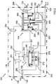
- Fig. 2 shows a device 120 for controlling the brake system according to an embodiment of the present invention.
- device 120 may be an embodiment of the invention Fig. 1 act described device.
- the device 120 has the supply connection 122 and the control connection 130 as input-side connections and the service brake connection 124, the supply connection 126 and the parking brake connection 128 as output-side connections.
- the device 120 includes a parking brake control valve 132, a trailer control valve 134 and a switchable valve assembly 136. As functional units, the device comprises the parking brake control valve 132, the trailer control valve 134 and the valve device 136.
- the device 120 comprises a housing 220, the ports 122, 124, 126, 128, 130 being integrated into a housing wall of the housing 220 surrounding the parking brake control valve 132, the trailer control valve 134 and the valve device 136.
- the parking brake control valve 132 has a first parking brake control valve port 241, a second parking brake control valve port 242, and a third parking brake control valve port 243.
- the trailer control valve 134 includes a first trailer control valve port 251, a second trailer control valve port 252, a third trailer control valve port 253, a fourth trailer control valve port 254, and a fifth trailer control valve port 255.
- the valve device 136 has four 2/2-way valves 261, 262, 263 and according to this embodiment, a 3/2-way valve 264.
- the valves 261, 262, 263, 264 are designed as solenoid valves.
- the first parking brake control valve port 241 of the parking brake control valve 132 is connected to the supply port via a check valve 266.
- the second parking brake control valve port 242 is connected to the parking brake port 128.
- a pressure measuring device 267 is coupled to a line connecting the second parking brake control valve port 242 and the parking brake port 128 in order to be able to detect pressure prevailing at the second parking brake control valve port 242.
- the third parking brake control valve port 243 is connected to the supply port 122 via a first 2/2-way valve 261 and a third 2/2-way valve 263 of the valve device 136 and via the check valve 266.
- a second port of the second 2/2-way valve 262 is open and a second port of the third 2/2-way valve 263 is connected to the third parking brake control valve port.
- the 3/2-way valve 264 is connected between the control port 130 and the fifth trailer control valve port 255.
- the supply port 122 is connected to the first trailer control valve port 251.
- the second trailer control valve port 252 is connected to the service brake port 124, wherein another pressure measuring device 268 is coupled to a line connecting the second trailer control valve port 252 and the service brake port 124 to detect a pressure prevailing at the second trailer control valve port 252.
- the third trailer control valve port 253 is connected to the supply port 126.
- the parking brake control valve 132 is configured to connect the second parking brake control valve port 242 to the first parking brake control valve port 241 when the third parking brake control port port 243 is vented.
- the parking brake control valve 132 is configured to disconnect the second parking brake control valve port 242 from the first parking brake control valve port 241.
- a piston 270 is disposed on the movable between a first and a second position. The piston 270 is pressed with a vented third parking brake control valve port 243 by a spring against the third parking brake control valve port 243.
- a connection opening between the first parking brake control valve connection 241 and the second parking brake control valve connection 242 is closed via a further piston 272.
- the further piston 272 has a passage opening through which the second parking brake control valve port 242 is connected to a vent opening of the parking brake control valve 132 when the piston 270 is in the first position.
- the piston 270 is moved against the spring force of the spring to the second position and presses against the further piston 272.
- the further piston 272 is moved by the pressure of the piston 270 and gives the connection opening between the first Park brake control valve port 241 and the second parking brake control valve port 242 free, so that the second parking brake control valve port 242 is vented.
- the passage opening of the further piston 272 is closed by the piston 270.
- the trailer control valve 134 includes a parking brake piston 280, a slidable valve seat 282, and another piston 284.
- a parking brake piston 280 abuts against the slidable valve seat 282, communication between the first trailer control valve port 251 and the second trailer control valve port 252 is disconnected.
- the parking brake piston 280 is not abutting the slidable valve seat 282, the connection between the first trailer control valve port 251 and the second trailer control valve port 252.
- the fourth trailer control valve port 254 is vented, the parking brake piston 280 is moved to a first end position in which the parking brake piston 280 of the valve seat 282 is lifted.
- the valve seat 282 In the first end position of the parking brake piston 280, the valve seat 282 is against the piston 284, whereby a vent opening of the trailer control valve 134 is closed.
- the park brake piston 280 When the fourth trailer control valve port 254 is vented, the park brake piston 280 is moved to a second end position in which the park brake piston 280 abuts the valve seat 282.
- the valve seat 282 In the second end position of the parking brake piston 280, the valve seat 282 is removed from the piston 284, whereby the vent opening of the trailer control valve 134 is connected to the second trailer control valve port 252, thereby venting the second trailer control valve port 252 in a vented manner.
- the piston 284 of the trailer control valve 134 is urged by a spring toward the fifth trailer control valve port 255.
- the piston 285 is displaced toward the valve seat 282 and presses against the valve seat 282. This closes the vent opening of the trailer control valve 134 and removes the valve seat 282 from the parking brake piston 280, thus relieving the connection between the second trailer control valve port 252 and the third trailer control valve port 253 is established when the parking brake piston 280 is in the first position, and remains when the parking brake piston 280 is in the second position.
- the valve device 136 is in a first valve position, in which the supply port 122 is separated from the third parking brake control valve port 243 and the fourth trailer control valve port 254.
- the first 2/2-way valve 261 in a blocking position
- the second 2/2-way valve 262 in a blocking position
- the third 2/2-way valve 263 connected in a passage position.
- the 3/2-way valve 264 is switched to a passage position in which the control port 130 is connected to the fifth trailer control valve port 255.
- the first parking brake control valve port 241 and the first trailer control valve port 251 are vented, as shown in the first valve position of the valve device 136.
- the third parking brake control valve port 243 is vented, so that the second parking brake control valve port 242 is vented. This causes an activation of the parking brake of the commercial vehicle via the vented parking brake port 128 according to this embodiment.
- the fourth trailer control valve port 254 is vented, so that the second trailer control valve port 252 is vented.
- the third trailer control valve port 253 is vented regardless of the position of the parking brake piston 280. This causes according to this embodiment, an activation of the service brake of the trailer of the commercial vehicle via the vented service brake port 124 and the vented supply port 126th
- the third 2/2-way valve 263 disconnects the control line of the trailer control valve 134 from the control line of the parking brake control valve 132.
- the valves 261, 262, 263 of the valve device 136 for example, from the in Fig. 1 be called accordingly controlled electronic control device.
- device 120 is provided for trucks with a parking strategy in which the brake of the trailer is activated when the parking brake of the towing vehicle is activated.
- Fig. 3 shows a device 120 for controlling the brake system according to an embodiment of the present invention.
- device 120 may be an embodiment of the invention Fig. 1 act described device.
- the device 120 corresponds to that of FIG Fig. 2 with the difference that the valve device 136 is shown in the second valve position in which the supply port 122 is disconnected from the third parking brake control valve port and connected to the fourth trailer control valve port 254.
- the first parking brake control valve port 241 and the first trailer control valve port 251 are vented.
- the third parking brake control valve port 243 is vented, so that the second parking brake control valve port 242 is vented. This causes an activation of the parking brake of the commercial vehicle via the vented parking brake port 128 according to this embodiment.
- the fourth trailer control valve port 254 is vented, so that the second trailer control valve port 252 is vented.
- the third trailer control valve port 253 is vented. This causes according to this embodiment, no activation of the service brake of the trailer of the commercial vehicle, since the service brake port 124 is vented.
- the third 2/2-way valve 263 opens the connection to the control line of the parking brake control valve 132.
- the valves 261, 262, 263 of the valve device 136 for example, from the in Fig. 1 be called accordingly controlled electronic control device.
- device 120 is provided for trucks with a parking strategy in which an activation of the parking brake of the towing vehicle does not lead to an activation of the brake of the trailer.
- Fig. 4 shows a device 120 for controlling the brake system according to an embodiment of the present invention.
- device 120 may be an embodiment of the invention Fig. 1 act described device.
- the device 120 corresponds to that of FIG Fig. 2 with the difference that a feedback valve 466 is connected between the fourth trailer control valve port 254 and the second parking brake control valve port 242.
- the feedback valve 466 is designed as a solenoid valve in the form of a 2/2-way valve.
- the third 2/2-way valve 263 and the feedback valve 466 disconnect the control line of the trailer control valve 134 from the control line of the parking brake control valve 132.
- the valves 261, 262, 263 of the valve device 136 for example, from the in Fig. 1 be called accordingly controlled electronic control device.
- device 120 is provided for trucks with a parking strategy in which the brake of the trailer is activated when the parking brake of the towing vehicle is activated.
- Fig. 5 shows a device 120 for controlling the brake system according to an embodiment of the present invention.
- device 120 may be an embodiment of the invention Fig. 1 act described device.
- the device 120 corresponds to that of FIG Fig. 3 described device, with the difference that the feedback valve 466, as shown by Fig. 5 is connected between the second parking brake control valve port 242 and the third parking brake valve port 243 is connected.
- the third 2/2-way valve 263 opens the connection to the control line of the parking brake control valve 132.
- the valves 261, 262, 263 of the valve device 136 for example, from the in Fig. 1 be called accordingly controlled electronic control device.
- device 120 is provided for trucks with a parking strategy in which an activation of the parking brake of the towing vehicle does not lead to an activation of the brake of the trailer.
- the 466 feedback valve is not necessary for the safe venting of leaks.
- By omitting the feedback valve 466 results for the application of Volvotrucks according to an embodiment of in Fig. 3 shown scheme.
- control pressure for the parking brake control valve 132 (PBRV) and the control pressure for the TCM parking brake function are generated by the functional unit EPB.
- the control unit TCM generates the control pressure for the function of the electric brake.
- a piston, namely the parking brake piston 280 in the TCM is designed with a double use.
- a parking brake piston 280 for the parking function of the TCM and the other as a parking brake piston 280 for the electrical braking of the TCM.
- the total number of solenoid valves 261, 262, 263, 264 can be kept low.
- the use of the parking brake piston 280 twice for parking brake function and electric braking requires only a few pistons.
- a common electronic unit offers cost savings compared to two electronic units.
- pressure sensors 267, 268 in the EPB part and in the TCM part are used according to an exemplary embodiment to mutually plausibility the correct sensor function.
- TCM components can be designed easily.
- the TCM functionality can be implemented to save space.
- an integration of EPB housing and TCM housing can be realized. This eliminates lines and fittings between otherwise separate housings for EPB and TCM.
- a common control pressure generation for EPB and TCM is realized using two 2/2 solenoid valves 261, 263, a 3/2 solenoid valve and a proportional valve.
- a feedback of the EPB (spring store to control line PBRV) takes place.
- the feedback is switched and only available if there is no pressure regulation.
- the feedback is designed as a throttle in the EPB piston.
Claims (11)
- Système (120) de commande d'un système de frein d'un véhicule (100) utilitaire, ayant les caractéristiques suivantes :un raccord (122) d'alimentation pour procurer de l'air comprimé, un raccord (124) de frein de service pour accoupler le système (120) à une tête (114) d'accouplement d'un conduit de frein d'une remorque (102) du véhicule (100) utilitaire, un raccord (126) de réservoir pour accoupler le système (120) à une tête (116) d'accouplement d'une alimentation de la remorque (102) et un raccord (128) de frein de stationnement pour accoupler le système (120) à un frein (118) de stationnement du véhicule (100) utilitaire ;une soupape (132) de commande du frein de stationnement pour procurer une fonction de frein de stationnement du véhicule (100) utilitaire ;une soupape (132) de commande de frein de stationnement pour procurer une fonction de frein de stationnement au véhicule (100) utilitaire, la soupape (132) de commande de frein de stationnement ayant un premier raccord (241) de soupape de commande de frein de stationnement, un deuxième raccord (242) de soupape de commande de frein de stationnement et un troisième raccord (243) de soupape de commande de frein de stationnement, le premier raccord (241) de soupape de commande de frein de stationnement communiquant avec le raccord (122) d'alimentation et le deuxième raccord (242) de soupape de commande de frein de stationnement communiquant avec le raccord (128) de frein de stationnement ;une soupape (134) de commande de remorque, pour procurer une fonction de frein d'arrêt et une fonction du freinage électrique de la remorque (102), la soupape (134) de commande de remorque ayant un premier raccord (251) de soupape de commande de remorque, un deuxième raccord (252) de soupape de commande de remorque un troisième raccord (253) de soupape de commande de remorque et un quatrième raccord (254) de soupape de commande de remorque, le premier raccord (251) de soupape de commande de remorque communiquant avec le raccord (122) d'alimentation, le deuxième raccord (252) de soupape de commande de remorque communiquant avec le raccord (124) de frein de service et le troisième raccord (253) de soupape de commande de remorque communiquant avec le raccord (126) de réservoir et la soupape (134) de commande de remorque ayant un piston (280) de frein de stationnement, qui est monté coulissant pour, en fonction d'un état d'alimentation en air du quatrième raccord (254) de soupape de commande de remorque, commander une alimentation en air du deuxième raccord (252) de soupape de commande de remorque par l'intermédiaire du premier raccord (251) de soupape de commande de remorque, pour procurer la fonction de frein d'arrêt et commander la fonction du freinage électrique etun dispositif (136) de soupape commutable, pour faire communiquer de manière commutable le raccord (132) d'alimentation avec le troisième raccord (243) de soupape de commande de frein de stationnement et/ou avec le quatrième raccord (254) de soupape de commande de remorque, afin de provoquer la mise à disposition de la fonction de frein de stationnement du véhicule (100) utilitaire, ainsi que la mise à disposition de la fonction de frein d'arrêt et de la fonction de freinage électrique de la remorque (102) .
- Système (120) suivant la revendication 1, dans lequel le dispositif (136) de soupape commutable est constitué pour la communication commutable du raccord (122) d'alimentation avec le troisième raccord (243) de soupape de commande de frein de stationnement et le quatrième raccord (254) de soupape de commande de remorque.
- Système (120) suivant l'une des revendications précédentes, dans lequel la soupape (132) de commande de frein de stationnement est constituée pour mettre le deuxième raccord (242) de soupape de commande de frein de stationnement en communication avec le premier raccord (241) de soupape de commande de frein de stationnement, si le troisième raccord (243) de soupape de commande de frein de stationnement est alimenté en air, et est constitué pour séparer le deuxième raccord (242) de soupape de commande de frein de stationnement du premier raccord (241) de soupape de commande de frein de stationnement, si le troisième raccord (243) de soupape de commande de frein de stationnement est purgé.
- Système (120) suivant l'une des revendications précédentes, dans lequel le piston (280) de frein de stationnement de la soupape (134) de commande de remorque est monté coulissant, afin d'être, conformément à une purge du quatrième raccord (254) de soupape de commande de remorque, mis dans une première position d'extrémité, grâce à quoi le piston (280) de frein de stationnement est soulevé d'un siège (282) de soupape, de sorte que le premier raccord (251) de commande de remorque communique avec le deuxième raccord (252) de soupape de commande de remorque, et d'être, conformément à une alimentation en air du quatrième raccord (254) de soupape de commande de remorque, mis dans une deuxième position d'extrémité, grâce à quoi le piston (280) de frein de stationnement s'applique au siège (282) de la soupape, de sorte que le premier raccord (251) de soupape de commande de remorque est séparé du deuxième raccord (252) de soupape de commande de remorque.
- Système (120) suivant la revendication 4, comprenant un raccord (130) de commande, pour accoupler le système (120) à une soupape (110) de frein à pied, la soupape (34) de commande de remorque ayant un cinquième raccord (255) de soupape de commande de remorque, qui est accouplé au raccord (130) de commande, et un piston (284), qui est monté coulissant pour être, conformément à une alimentation en air du cinquième raccord (255) de soupape de commande de remorque, déplacé à l'encontre d'une force de ressort en direction du siège (282) de la soupape et poussé sur le siège (282) de la soupape, grâce à quoi le siège (282) de la soupape est déplacé, de sorte que le premier raccord (251) de soupape de commande de remorque communique avec le deuxième raccord (252) de soupape de commande de remorque.
- Système (120) suivant la revendication 5, dans lequel la soupape (134) de commande de remorque n'a, outre le quatrième raccord (254) de soupape de commande de remorque et le cinquième raccord (255) de soupape de commande de remorque, pas d'autres raccords de commande.
- Système (120) suivant l'une des revendications précédentes, comprenant un boîtier (220) ayant une paroi, la paroi du boîtier entourant la soupape (132) de commande de frein de stationnement, la soupape (134) de commande de remorque et le dispositif (136) de soupape, et ayant le raccord (124) de frein de service, le raccord (126) de réservoir et le raccord (128) de frein de stationnement.
- Système (120) suivant l'une des revendications précédentes, dans lequel le dispositif (136) de soupape a une première soupape (261) à 2/2 voies, un premier raccord de la première soupape (261) à 2/2 voies communiquant avec le raccord (122) d'alimentation et un deuxième raccord de la première soupape (261) à 2/2 voies communiquant avec le quatrième raccord de soupape de commande de remorque, une deuxième soupape (262) à 2/2 voies, un premier raccord de la deuxième soupape à 2/2 voies communiquant avec le quatrième raccord (254) de soupape de commande de remorque et un deuxième raccord de la deuxième soupape (262) à 2/2 voies communiquant avec une purge, et une troisième soupape (263) à 2/2 voies, un premier raccord de la troisième soupape (263) à 2/2 voies communiquant avec le quatrième raccord (254) de soupape de commande de remorque et un deuxième raccord de la troisième soupape (263) à 2/2 voie communiquant avec le troisième raccord (243) de soupape de commande de frein de stationnement.
- Système (120) suivant la revendication 8, dans lequel les soupapes (261, 262, 263) à plusieurs voies peuvent être commandées, afin de provoquer la mise à disposition de la fonction de frein de stationnement par la soupape (132) de commande de frein de stationnement, ainsi que la mise à disposition de la fonction de frein d'arrêt et de la fonction du freinage électrique par la soupape (134) de commande de remorque.
- Système (120) suivant la revendication 9, dans lequel le dispositif (136) de soupape a une quatrième soupape (466) à 2/2 voies, un premier raccord de la quatrième soupape (466) à 2/2 voies communiquant avec le deuxième raccord (242) de soupape de commande de frein de stationnement et un deuxième raccord de la quatrième soupape (466) à 2/2 voies communiquant avec le troisième raccord (243) de la soupape de commande de frein de stationnement.
- Installation de freinage d'un véhicule (100) utilitaire ayant les caractéristiques suivantes :un système (120) suivant l'une des revendications précédentes ;une alimentation (112) en air comprimé, qui communique avec le système (120) par le raccord (122) d'alimentation, une tête (114) d'accouplement d'un conduit de frein de remorque, qui communique avec le système (120) par le raccord (124) de frein, une tête (116) d'accouplement d'une alimentation de remorque, qui communique avec le système (120) par le raccord (126) de réservoir et un frein (118) de stationnement, qui communique avec le système (120) par le raccord (128) de frein de stationnement etun dispositif (138) électronique de commande, constitué pour procurer au moins un signal de commande à au moins une entrée de commande du dispositif (136) de soupape.
Applications Claiming Priority (2)
| Application Number | Priority Date | Filing Date | Title |
|---|---|---|---|
| DE102015107125.8A DE102015107125B4 (de) | 2015-05-07 | 2015-05-07 | Vorrichtung zum Steuern einer Bremsanlage für ein Nutzfahrzeug und Bremsanlage |
| PCT/EP2016/000748 WO2016177475A1 (fr) | 2015-05-07 | 2016-05-06 | Dispositif de commande d'un système de freinage pour un véhicule utilitaire et système de freinage |
Publications (2)
| Publication Number | Publication Date |
|---|---|
| EP3292030A1 EP3292030A1 (fr) | 2018-03-14 |
| EP3292030B1 true EP3292030B1 (fr) | 2019-07-10 |
Family
ID=55953102
Family Applications (1)
| Application Number | Title | Priority Date | Filing Date |
|---|---|---|---|
| EP16721362.8A Active EP3292030B1 (fr) | 2015-05-07 | 2016-05-06 | Dispositif de commande d'un système de freinage pour un véhicule utilitaire et système de freinage |
Country Status (5)
| Country | Link |
|---|---|
| EP (1) | EP3292030B1 (fr) |
| CN (1) | CN107580571B (fr) |
| BR (1) | BR112017022959B1 (fr) |
| DE (1) | DE102015107125B4 (fr) |
| WO (1) | WO2016177475A1 (fr) |
Cited By (1)
| Publication number | Priority date | Publication date | Assignee | Title |
|---|---|---|---|---|
| US11267447B2 (en) | 2017-09-07 | 2022-03-08 | Knorr-Bremse Systeme Fuer Nutzfahrzeuge Gmbh | Electropneumatic parking brake control device, and braking system of a vehicle |
Families Citing this family (13)
| Publication number | Priority date | Publication date | Assignee | Title |
|---|---|---|---|---|
| DE102017006356A1 (de) * | 2017-03-21 | 2018-09-27 | Wabco Gmbh | Elektro-Pneumatische Handbremse (EPH) mit integriertem TCV (Europäische Ansteuerung) |
| DE102017005980A1 (de) | 2017-03-21 | 2018-09-27 | Wabco Gmbh | Integriertes Anhängersteuermodul (TCV) mit externer elektropneumatischer Handbremseinheit (EPH) |
| US20180273004A1 (en) * | 2017-03-27 | 2018-09-27 | Bendix Commercial Vehicle Systems Llc | Valve system and method for controlling same |
| US10442418B2 (en) | 2017-03-27 | 2019-10-15 | Bendix Commercial Vehicle Systems Llc | Valve system and method for controlling same |
| SE542149C2 (en) * | 2017-10-03 | 2020-03-03 | Scania Cv Ab | A control device for a vehicle comprising a selector means with a parking brake position and a vehicle comprising such a control device |
| DE102017009307A1 (de) * | 2017-10-07 | 2019-04-11 | Wabco Gmbh | Parkbrems-Ventileinrichtung |
| DE102018114642A1 (de) * | 2018-06-19 | 2019-12-19 | Knorr-Bremse Systeme für Nutzfahrzeuge GmbH | Parkbremseinrichtung für ein Kraftfahrzeug |
| DE102018118745A1 (de) | 2018-08-02 | 2020-02-06 | Wabco Gmbh | Elektro-Pneumatische Handbremse (EPH) mit teilweise entkoppelten TCV (Europäische Ansteuerung) |
| DE102019118896A1 (de) | 2019-07-12 | 2021-01-14 | Knorr-Bremse Systeme für Nutzfahrzeuge GmbH | Parkbremseinrichtung |
| DE102019118895A1 (de) * | 2019-07-12 | 2021-01-14 | Knorr-Bremse Systeme für Nutzfahrzeuge GmbH | Parkbremseinrichtung für ein Nutzfahrzeug |
| CN112937535B (zh) * | 2021-04-08 | 2022-04-19 | 中铁工程装备集团有限公司 | 一种液压驻车及应急拖车控制装置和轮式工程车辆 |
| WO2023062189A1 (fr) | 2021-10-16 | 2023-04-20 | Knorr-Bremse Systeme für Nutzfahrzeuge GmbH | Module de commande de remorque pour dispositif de freinage et dispositif de frein de stationnement |
| DE102022101439A1 (de) | 2021-10-16 | 2023-04-20 | Knorr-Bremse Systeme für Nutzfahrzeuge GmbH | Anhängersteuermodul für Bremseinrichtung und Parkbremseinrichtung |
Family Cites Families (15)
| Publication number | Priority date | Publication date | Assignee | Title |
|---|---|---|---|---|
| DE19609222A1 (de) * | 1996-03-09 | 1997-09-11 | Bosch Gmbh Robert | Anhängersteuerventil für eine Druckluftbremsanlage für Kraftfahrzeuge |
| EP1366964B2 (fr) * | 2002-05-31 | 2010-11-24 | KNORR-BREMSE Systeme für Nutzfahrzeuge GmbH | Système de freinage de stationnement pour véhicules et procédé pour faire fonctionner |
| DE10310235B4 (de) * | 2003-03-08 | 2020-12-17 | Wabco Gmbh | Steuereinrichtung für Anhängefahrzeug |
| DE10336611A1 (de) * | 2003-08-08 | 2005-03-03 | Wabco Gmbh & Co.Ohg | Druckmittelbetriebene Bremsanlage für ein Fahrzeug |
| ITTO20050498A1 (it) * | 2005-07-20 | 2007-01-21 | Knorr Bremse Systeme | Impianto pneumatico per la frenatura di un veicolo commerciale |
| DE102005051686A1 (de) * | 2005-10-28 | 2007-05-03 | Knorr-Bremse Systeme für Nutzfahrzeuge GmbH | Elektro-pneumatisches Anhängersteuermodul |
| DE102006036748A1 (de) * | 2006-08-05 | 2008-02-07 | Wabco Gmbh | Elektrisch gesteuerte Bremsanlage |
| DE102007008504A1 (de) * | 2007-02-21 | 2008-08-28 | Wabco Gmbh | Feststellbremsmodul für druckmittelbetriebene Bremsanlage |
| DE102008009882A1 (de) * | 2008-02-19 | 2009-08-20 | Wabco Gmbh | Feststellbremse für ein Fahrzeug und Verfahren zum Betrieb der Feststellbremse |
| DE102008014458A1 (de) * | 2008-03-14 | 2009-09-17 | Wabco Gmbh | Bremsanlage für ein Fahrzeug |
| DE102008027733B4 (de) * | 2008-06-11 | 2012-07-12 | Knorr-Bremse Systeme für Nutzfahrzeuge GmbH | Parkbremsventilanordnung für ein Bremssystem eines Nutzfahrzeuges |
| DE102008048207C5 (de) * | 2008-09-20 | 2015-02-26 | Haldex Brake Products Gmbh | Elektrisch betätigbare Bremseinrichtung und Verfahren zum Betrieb derselben |
| DE102011053707B4 (de) * | 2011-09-16 | 2017-01-26 | Haldex Brake Products Aktiebolag | Druckluftaufbereitungseinheit |
| WO2013093545A1 (fr) * | 2011-12-23 | 2013-06-27 | Renault Trucks | Système de frein pneumatique à commande électronique pour un véhicule automobile et véhicule automobile équipé d'un tel système |
| DE102013107503A1 (de) * | 2013-07-16 | 2015-01-22 | Knorr-Bremse Systeme für Nutzfahrzeuge GmbH | Feststellbremseinrichtung für ein Zugfahrzeug einer Zugfahrzeug-Anhängerkombination mit nachrüstbarer Streckbremsventileinrichtung |
-
2015
- 2015-05-07 DE DE102015107125.8A patent/DE102015107125B4/de active Active
-
2016
- 2016-05-06 EP EP16721362.8A patent/EP3292030B1/fr active Active
- 2016-05-06 BR BR112017022959-5A patent/BR112017022959B1/pt active IP Right Grant
- 2016-05-06 WO PCT/EP2016/000748 patent/WO2016177475A1/fr unknown
- 2016-05-06 CN CN201680026637.5A patent/CN107580571B/zh active Active
Non-Patent Citations (1)
| Title |
|---|
| None * |
Cited By (1)
| Publication number | Priority date | Publication date | Assignee | Title |
|---|---|---|---|---|
| US11267447B2 (en) | 2017-09-07 | 2022-03-08 | Knorr-Bremse Systeme Fuer Nutzfahrzeuge Gmbh | Electropneumatic parking brake control device, and braking system of a vehicle |
Also Published As
| Publication number | Publication date |
|---|---|
| CN107580571B (zh) | 2020-03-17 |
| WO2016177475A1 (fr) | 2016-11-10 |
| EP3292030A1 (fr) | 2018-03-14 |
| DE102015107125A1 (de) | 2016-11-10 |
| BR112017022959B1 (pt) | 2023-01-10 |
| CN107580571A (zh) | 2018-01-12 |
| BR112017022959A2 (pt) | 2018-07-17 |
| DE102015107125B4 (de) | 2022-01-05 |
Similar Documents
| Publication | Publication Date | Title |
|---|---|---|
| EP3292030B1 (fr) | Dispositif de commande d'un système de freinage pour un véhicule utilitaire et système de freinage | |
| EP2121397B1 (fr) | Module frein de stationnement pour dispositif de freinage actionné par fluide sous pression | |
| EP2059429B1 (fr) | Unité de soupape pour dispositif de commande de freinage électropneumatique | |
| EP2055542B1 (fr) | Dispositif de frein actionné par un moyen de pression d'un véhicule sur rail doté d'un module de frein fixe produisant une pression contraire pour des freins de remorque | |
| DE102008007877B3 (de) | Parkbremseinrichtung | |
| EP2939892B1 (fr) | Frein de stationnement électrique pour un véhicule | |
| EP2133250B1 (fr) | Agencement de soupape de frein de stationnement pour un système de freinage d'un véhicule utilitaire | |
| EP1785325B2 (fr) | Dispositif de réglage d'un système de freinage à air comprimé pour un véhicule | |
| EP3145769B1 (fr) | Moyen de commande de freinage électropneumatique avec purge automatique du frein à accumulation en cas de panne de courant | |
| EP3755589B1 (fr) | Équipement électropneumatique d'un véhicule | |
| EP3515771B1 (fr) | Système de frein de stationnement pour véhicule utilitaire | |
| EP3943351B1 (fr) | Frein électrique de stationnement | |
| DE102017005979A1 (de) | Elektro-Pneumatische Handbremse (EPH) mit integrierten TCV (skandinavische Ansteuerung | |
| EP2133247B1 (fr) | Agencement de soupape de freinage de stationnement | |
| DE102015112490B4 (de) | Elektro-pneumatische Steuereinrichtung einer elektro-pneumatischen Bremsanlage einer Zugfahrzeug-Anhängerkombination | |
| DE102007004758C5 (de) | Bremsanlage und Verfahren zum Steuern einer Bremsanlage für ein Nutzfahrzeug | |
| EP3870485B1 (fr) | Architecture de système de freinage électropneumatique sans redondance de freinage de fonctionnement pneumatique directe sur l'essieu arrière (1p1e) | |
| EP2129560A2 (fr) | Système de frein de stationnement pour véhicules utilitaires et procédé d'utilisation d'un système de frein de stationnement | |
| EP3668766A1 (fr) | Module d'alimentation de remorque électropneumatique permettant d'obtenir la pression d'alimentation de remorque | |
| EP4058334B1 (fr) | Module de commande électropneumatique | |
| EP1953054B1 (fr) | Installation de frein et procédé de commande d'une installation de frein pour un véhicule utilitaire | |
| WO2019072452A1 (fr) | Module de freinage de stationnement électropneumatique pour véhicules utilitaires comprenant des freins de stationnement à ressort accumulateur | |
| DE102017009954A1 (de) | Achsventilmodul und Relaisventilmodul einer Druckluftbremsanlage | |
| EP3112231B1 (fr) | Module de frein de stationnement, installation de freinage et vehicule ainsi equipe et procede de fonctionnement d'un dispositif de frein de stationnement avec un tel module | |
| DE102008003525A1 (de) | Pneumatische Feststellbremseinrichtung eines wenigstens zweiachsigen, eine gelenkte Vorderachse aufweisenden Anhängerfahrzeugs einer Zugfahrzeug-Anhängerkombination |
Legal Events
| Date | Code | Title | Description |
|---|---|---|---|
| STAA | Information on the status of an ep patent application or granted ep patent |
Free format text: STATUS: THE INTERNATIONAL PUBLICATION HAS BEEN MADE |
|
| PUAI | Public reference made under article 153(3) epc to a published international application that has entered the european phase |
Free format text: ORIGINAL CODE: 0009012 |
|
| STAA | Information on the status of an ep patent application or granted ep patent |
Free format text: STATUS: REQUEST FOR EXAMINATION WAS MADE |
|
| 17P | Request for examination filed |
Effective date: 20171207 |
|
| AK | Designated contracting states |
Kind code of ref document: A1 Designated state(s): AL AT BE BG CH CY CZ DE DK EE ES FI FR GB GR HR HU IE IS IT LI LT LU LV MC MK MT NL NO PL PT RO RS SE SI SK SM TR |
|
| AX | Request for extension of the european patent |
Extension state: BA ME |
|
| DAV | Request for validation of the european patent (deleted) | ||
| DAX | Request for extension of the european patent (deleted) | ||
| GRAP | Despatch of communication of intention to grant a patent |
Free format text: ORIGINAL CODE: EPIDOSNIGR1 |
|
| STAA | Information on the status of an ep patent application or granted ep patent |
Free format text: STATUS: GRANT OF PATENT IS INTENDED |
|
| INTG | Intention to grant announced |
Effective date: 20190206 |
|
| GRAS | Grant fee paid |
Free format text: ORIGINAL CODE: EPIDOSNIGR3 |
|
| GRAA | (expected) grant |
Free format text: ORIGINAL CODE: 0009210 |
|
| STAA | Information on the status of an ep patent application or granted ep patent |
Free format text: STATUS: THE PATENT HAS BEEN GRANTED |
|
| AK | Designated contracting states |
Kind code of ref document: B1 Designated state(s): AL AT BE BG CH CY CZ DE DK EE ES FI FR GB GR HR HU IE IS IT LI LT LU LV MC MK MT NL NO PL PT RO RS SE SI SK SM TR |
|
| REG | Reference to a national code |
Ref country code: GB Ref legal event code: FG4D Free format text: NOT ENGLISH |
|
| REG | Reference to a national code |
Ref country code: CH Ref legal event code: EP Ref country code: AT Ref legal event code: REF Ref document number: 1153249 Country of ref document: AT Kind code of ref document: T Effective date: 20190715 |
|
| REG | Reference to a national code |
Ref country code: DE Ref legal event code: R096 Ref document number: 502016005475 Country of ref document: DE |
|
| REG | Reference to a national code |
Ref country code: IE Ref legal event code: FG4D Free format text: LANGUAGE OF EP DOCUMENT: GERMAN |
|
| REG | Reference to a national code |
Ref country code: NL Ref legal event code: MP Effective date: 20190710 |
|
| REG | Reference to a national code |
Ref country code: LT Ref legal event code: MG4D |
|
| PG25 | Lapsed in a contracting state [announced via postgrant information from national office to epo] |
Ref country code: FI Free format text: LAPSE BECAUSE OF FAILURE TO SUBMIT A TRANSLATION OF THE DESCRIPTION OR TO PAY THE FEE WITHIN THE PRESCRIBED TIME-LIMIT Effective date: 20190710 Ref country code: PT Free format text: LAPSE BECAUSE OF FAILURE TO SUBMIT A TRANSLATION OF THE DESCRIPTION OR TO PAY THE FEE WITHIN THE PRESCRIBED TIME-LIMIT Effective date: 20191111 Ref country code: NL Free format text: LAPSE BECAUSE OF FAILURE TO SUBMIT A TRANSLATION OF THE DESCRIPTION OR TO PAY THE FEE WITHIN THE PRESCRIBED TIME-LIMIT Effective date: 20190710 Ref country code: LT Free format text: LAPSE BECAUSE OF FAILURE TO SUBMIT A TRANSLATION OF THE DESCRIPTION OR TO PAY THE FEE WITHIN THE PRESCRIBED TIME-LIMIT Effective date: 20190710 Ref country code: BG Free format text: LAPSE BECAUSE OF FAILURE TO SUBMIT A TRANSLATION OF THE DESCRIPTION OR TO PAY THE FEE WITHIN THE PRESCRIBED TIME-LIMIT Effective date: 20191010 Ref country code: NO Free format text: LAPSE BECAUSE OF FAILURE TO SUBMIT A TRANSLATION OF THE DESCRIPTION OR TO PAY THE FEE WITHIN THE PRESCRIBED TIME-LIMIT Effective date: 20191010 Ref country code: HR Free format text: LAPSE BECAUSE OF FAILURE TO SUBMIT A TRANSLATION OF THE DESCRIPTION OR TO PAY THE FEE WITHIN THE PRESCRIBED TIME-LIMIT Effective date: 20190710 Ref country code: SE Free format text: LAPSE BECAUSE OF FAILURE TO SUBMIT A TRANSLATION OF THE DESCRIPTION OR TO PAY THE FEE WITHIN THE PRESCRIBED TIME-LIMIT Effective date: 20190710 |
|
| PG25 | Lapsed in a contracting state [announced via postgrant information from national office to epo] |
Ref country code: RS Free format text: LAPSE BECAUSE OF FAILURE TO SUBMIT A TRANSLATION OF THE DESCRIPTION OR TO PAY THE FEE WITHIN THE PRESCRIBED TIME-LIMIT Effective date: 20190710 Ref country code: IS Free format text: LAPSE BECAUSE OF FAILURE TO SUBMIT A TRANSLATION OF THE DESCRIPTION OR TO PAY THE FEE WITHIN THE PRESCRIBED TIME-LIMIT Effective date: 20191110 Ref country code: GR Free format text: LAPSE BECAUSE OF FAILURE TO SUBMIT A TRANSLATION OF THE DESCRIPTION OR TO PAY THE FEE WITHIN THE PRESCRIBED TIME-LIMIT Effective date: 20191011 Ref country code: ES Free format text: LAPSE BECAUSE OF FAILURE TO SUBMIT A TRANSLATION OF THE DESCRIPTION OR TO PAY THE FEE WITHIN THE PRESCRIBED TIME-LIMIT Effective date: 20190710 Ref country code: LV Free format text: LAPSE BECAUSE OF FAILURE TO SUBMIT A TRANSLATION OF THE DESCRIPTION OR TO PAY THE FEE WITHIN THE PRESCRIBED TIME-LIMIT Effective date: 20190710 Ref country code: AL Free format text: LAPSE BECAUSE OF FAILURE TO SUBMIT A TRANSLATION OF THE DESCRIPTION OR TO PAY THE FEE WITHIN THE PRESCRIBED TIME-LIMIT Effective date: 20190710 |
|
| PG25 | Lapsed in a contracting state [announced via postgrant information from national office to epo] |
Ref country code: TR Free format text: LAPSE BECAUSE OF FAILURE TO SUBMIT A TRANSLATION OF THE DESCRIPTION OR TO PAY THE FEE WITHIN THE PRESCRIBED TIME-LIMIT Effective date: 20190710 |
|
| PG25 | Lapsed in a contracting state [announced via postgrant information from national office to epo] |
Ref country code: EE Free format text: LAPSE BECAUSE OF FAILURE TO SUBMIT A TRANSLATION OF THE DESCRIPTION OR TO PAY THE FEE WITHIN THE PRESCRIBED TIME-LIMIT Effective date: 20190710 Ref country code: PL Free format text: LAPSE BECAUSE OF FAILURE TO SUBMIT A TRANSLATION OF THE DESCRIPTION OR TO PAY THE FEE WITHIN THE PRESCRIBED TIME-LIMIT Effective date: 20190710 Ref country code: IT Free format text: LAPSE BECAUSE OF FAILURE TO SUBMIT A TRANSLATION OF THE DESCRIPTION OR TO PAY THE FEE WITHIN THE PRESCRIBED TIME-LIMIT Effective date: 20190710 Ref country code: DK Free format text: LAPSE BECAUSE OF FAILURE TO SUBMIT A TRANSLATION OF THE DESCRIPTION OR TO PAY THE FEE WITHIN THE PRESCRIBED TIME-LIMIT Effective date: 20190710 Ref country code: RO Free format text: LAPSE BECAUSE OF FAILURE TO SUBMIT A TRANSLATION OF THE DESCRIPTION OR TO PAY THE FEE WITHIN THE PRESCRIBED TIME-LIMIT Effective date: 20190710 |
|
| PG25 | Lapsed in a contracting state [announced via postgrant information from national office to epo] |
Ref country code: SK Free format text: LAPSE BECAUSE OF FAILURE TO SUBMIT A TRANSLATION OF THE DESCRIPTION OR TO PAY THE FEE WITHIN THE PRESCRIBED TIME-LIMIT Effective date: 20190710 Ref country code: CZ Free format text: LAPSE BECAUSE OF FAILURE TO SUBMIT A TRANSLATION OF THE DESCRIPTION OR TO PAY THE FEE WITHIN THE PRESCRIBED TIME-LIMIT Effective date: 20190710 Ref country code: IS Free format text: LAPSE BECAUSE OF FAILURE TO SUBMIT A TRANSLATION OF THE DESCRIPTION OR TO PAY THE FEE WITHIN THE PRESCRIBED TIME-LIMIT Effective date: 20200224 Ref country code: SM Free format text: LAPSE BECAUSE OF FAILURE TO SUBMIT A TRANSLATION OF THE DESCRIPTION OR TO PAY THE FEE WITHIN THE PRESCRIBED TIME-LIMIT Effective date: 20190710 |
|
| REG | Reference to a national code |
Ref country code: DE Ref legal event code: R097 Ref document number: 502016005475 Country of ref document: DE |
|
| PLBE | No opposition filed within time limit |
Free format text: ORIGINAL CODE: 0009261 |
|
| STAA | Information on the status of an ep patent application or granted ep patent |
Free format text: STATUS: NO OPPOSITION FILED WITHIN TIME LIMIT |
|
| PG2D | Information on lapse in contracting state deleted |
Ref country code: IS |
|
| 26N | No opposition filed |
Effective date: 20200603 |
|
| PG25 | Lapsed in a contracting state [announced via postgrant information from national office to epo] |
Ref country code: SI Free format text: LAPSE BECAUSE OF FAILURE TO SUBMIT A TRANSLATION OF THE DESCRIPTION OR TO PAY THE FEE WITHIN THE PRESCRIBED TIME-LIMIT Effective date: 20190710 |
|
| PG25 | Lapsed in a contracting state [announced via postgrant information from national office to epo] |
Ref country code: CH Free format text: LAPSE BECAUSE OF NON-PAYMENT OF DUE FEES Effective date: 20200531 Ref country code: LI Free format text: LAPSE BECAUSE OF NON-PAYMENT OF DUE FEES Effective date: 20200531 Ref country code: MC Free format text: LAPSE BECAUSE OF FAILURE TO SUBMIT A TRANSLATION OF THE DESCRIPTION OR TO PAY THE FEE WITHIN THE PRESCRIBED TIME-LIMIT Effective date: 20190710 |
|
| REG | Reference to a national code |
Ref country code: BE Ref legal event code: MM Effective date: 20200531 |
|
| GBPC | Gb: european patent ceased through non-payment of renewal fee |
Effective date: 20200506 |
|
| PG25 | Lapsed in a contracting state [announced via postgrant information from national office to epo] |
Ref country code: LU Free format text: LAPSE BECAUSE OF NON-PAYMENT OF DUE FEES Effective date: 20200506 |
|
| PG25 | Lapsed in a contracting state [announced via postgrant information from national office to epo] |
Ref country code: FR Free format text: LAPSE BECAUSE OF NON-PAYMENT OF DUE FEES Effective date: 20200531 Ref country code: GB Free format text: LAPSE BECAUSE OF NON-PAYMENT OF DUE FEES Effective date: 20200506 Ref country code: IE Free format text: LAPSE BECAUSE OF NON-PAYMENT OF DUE FEES Effective date: 20200506 |
|
| PG25 | Lapsed in a contracting state [announced via postgrant information from national office to epo] |
Ref country code: BE Free format text: LAPSE BECAUSE OF NON-PAYMENT OF DUE FEES Effective date: 20200531 |
|
| PG25 | Lapsed in a contracting state [announced via postgrant information from national office to epo] |
Ref country code: MT Free format text: LAPSE BECAUSE OF FAILURE TO SUBMIT A TRANSLATION OF THE DESCRIPTION OR TO PAY THE FEE WITHIN THE PRESCRIBED TIME-LIMIT Effective date: 20190710 Ref country code: CY Free format text: LAPSE BECAUSE OF FAILURE TO SUBMIT A TRANSLATION OF THE DESCRIPTION OR TO PAY THE FEE WITHIN THE PRESCRIBED TIME-LIMIT Effective date: 20190710 |
|
| PG25 | Lapsed in a contracting state [announced via postgrant information from national office to epo] |
Ref country code: MK Free format text: LAPSE BECAUSE OF FAILURE TO SUBMIT A TRANSLATION OF THE DESCRIPTION OR TO PAY THE FEE WITHIN THE PRESCRIBED TIME-LIMIT Effective date: 20190710 |
|
| REG | Reference to a national code |
Ref country code: AT Ref legal event code: MM01 Ref document number: 1153249 Country of ref document: AT Kind code of ref document: T Effective date: 20210506 |
|
| PG25 | Lapsed in a contracting state [announced via postgrant information from national office to epo] |
Ref country code: AT Free format text: LAPSE BECAUSE OF NON-PAYMENT OF DUE FEES Effective date: 20210506 |
|
| P01 | Opt-out of the competence of the unified patent court (upc) registered |
Effective date: 20230508 |
|
| PGFP | Annual fee paid to national office [announced via postgrant information from national office to epo] |
Ref country code: DE Payment date: 20230519 Year of fee payment: 8 |