EP3292030B1 - Device for controlling a braking system for a utility vehicle and braking system - Google Patents
Device for controlling a braking system for a utility vehicle and braking system Download PDFInfo
- Publication number
- EP3292030B1 EP3292030B1 EP16721362.8A EP16721362A EP3292030B1 EP 3292030 B1 EP3292030 B1 EP 3292030B1 EP 16721362 A EP16721362 A EP 16721362A EP 3292030 B1 EP3292030 B1 EP 3292030B1
- Authority
- EP
- European Patent Office
- Prior art keywords
- control valve
- port
- parking brake
- trailer
- valve port
- Prior art date
- Legal status (The legal status is an assumption and is not a legal conclusion. Google has not performed a legal analysis and makes no representation as to the accuracy of the status listed.)
- Active
Links
Images


Classifications
-
- B—PERFORMING OPERATIONS; TRANSPORTING
- B60—VEHICLES IN GENERAL
- B60T—VEHICLE BRAKE CONTROL SYSTEMS OR PARTS THEREOF; BRAKE CONTROL SYSTEMS OR PARTS THEREOF, IN GENERAL; ARRANGEMENT OF BRAKING ELEMENTS ON VEHICLES IN GENERAL; PORTABLE DEVICES FOR PREVENTING UNWANTED MOVEMENT OF VEHICLES; VEHICLE MODIFICATIONS TO FACILITATE COOLING OF BRAKES
- B60T13/00—Transmitting braking action from initiating means to ultimate brake actuator with power assistance or drive; Brake systems incorporating such transmitting means, e.g. air-pressure brake systems
- B60T13/10—Transmitting braking action from initiating means to ultimate brake actuator with power assistance or drive; Brake systems incorporating such transmitting means, e.g. air-pressure brake systems with fluid assistance, drive, or release
- B60T13/66—Electrical control in fluid-pressure brake systems
-
- B—PERFORMING OPERATIONS; TRANSPORTING
- B60—VEHICLES IN GENERAL
- B60T—VEHICLE BRAKE CONTROL SYSTEMS OR PARTS THEREOF; BRAKE CONTROL SYSTEMS OR PARTS THEREOF, IN GENERAL; ARRANGEMENT OF BRAKING ELEMENTS ON VEHICLES IN GENERAL; PORTABLE DEVICES FOR PREVENTING UNWANTED MOVEMENT OF VEHICLES; VEHICLE MODIFICATIONS TO FACILITATE COOLING OF BRAKES
- B60T13/00—Transmitting braking action from initiating means to ultimate brake actuator with power assistance or drive; Brake systems incorporating such transmitting means, e.g. air-pressure brake systems
- B60T13/10—Transmitting braking action from initiating means to ultimate brake actuator with power assistance or drive; Brake systems incorporating such transmitting means, e.g. air-pressure brake systems with fluid assistance, drive, or release
- B60T13/24—Transmitting braking action from initiating means to ultimate brake actuator with power assistance or drive; Brake systems incorporating such transmitting means, e.g. air-pressure brake systems with fluid assistance, drive, or release the fluid being gaseous
- B60T13/26—Compressed-air systems
-
- B—PERFORMING OPERATIONS; TRANSPORTING
- B60—VEHICLES IN GENERAL
- B60T—VEHICLE BRAKE CONTROL SYSTEMS OR PARTS THEREOF; BRAKE CONTROL SYSTEMS OR PARTS THEREOF, IN GENERAL; ARRANGEMENT OF BRAKING ELEMENTS ON VEHICLES IN GENERAL; PORTABLE DEVICES FOR PREVENTING UNWANTED MOVEMENT OF VEHICLES; VEHICLE MODIFICATIONS TO FACILITATE COOLING OF BRAKES
- B60T13/00—Transmitting braking action from initiating means to ultimate brake actuator with power assistance or drive; Brake systems incorporating such transmitting means, e.g. air-pressure brake systems
- B60T13/10—Transmitting braking action from initiating means to ultimate brake actuator with power assistance or drive; Brake systems incorporating such transmitting means, e.g. air-pressure brake systems with fluid assistance, drive, or release
- B60T13/66—Electrical control in fluid-pressure brake systems
- B60T13/68—Electrical control in fluid-pressure brake systems by electrically-controlled valves
-
- B—PERFORMING OPERATIONS; TRANSPORTING
- B60—VEHICLES IN GENERAL
- B60T—VEHICLE BRAKE CONTROL SYSTEMS OR PARTS THEREOF; BRAKE CONTROL SYSTEMS OR PARTS THEREOF, IN GENERAL; ARRANGEMENT OF BRAKING ELEMENTS ON VEHICLES IN GENERAL; PORTABLE DEVICES FOR PREVENTING UNWANTED MOVEMENT OF VEHICLES; VEHICLE MODIFICATIONS TO FACILITATE COOLING OF BRAKES
- B60T7/00—Brake-action initiating means
- B60T7/02—Brake-action initiating means for personal initiation
- B60T7/04—Brake-action initiating means for personal initiation foot actuated
-
- B—PERFORMING OPERATIONS; TRANSPORTING
- B60—VEHICLES IN GENERAL
- B60T—VEHICLE BRAKE CONTROL SYSTEMS OR PARTS THEREOF; BRAKE CONTROL SYSTEMS OR PARTS THEREOF, IN GENERAL; ARRANGEMENT OF BRAKING ELEMENTS ON VEHICLES IN GENERAL; PORTABLE DEVICES FOR PREVENTING UNWANTED MOVEMENT OF VEHICLES; VEHICLE MODIFICATIONS TO FACILITATE COOLING OF BRAKES
- B60T7/00—Brake-action initiating means
- B60T7/12—Brake-action initiating means for automatic initiation; for initiation not subject to will of driver or passenger
- B60T7/20—Brake-action initiating means for automatic initiation; for initiation not subject to will of driver or passenger specially for trailers, e.g. in case of uncoupling of or overrunning by trailer
-
- B—PERFORMING OPERATIONS; TRANSPORTING
- B60—VEHICLES IN GENERAL
- B60T—VEHICLE BRAKE CONTROL SYSTEMS OR PARTS THEREOF; BRAKE CONTROL SYSTEMS OR PARTS THEREOF, IN GENERAL; ARRANGEMENT OF BRAKING ELEMENTS ON VEHICLES IN GENERAL; PORTABLE DEVICES FOR PREVENTING UNWANTED MOVEMENT OF VEHICLES; VEHICLE MODIFICATIONS TO FACILITATE COOLING OF BRAKES
- B60T8/00—Arrangements for adjusting wheel-braking force to meet varying vehicular or ground-surface conditions, e.g. limiting or varying distribution of braking force
- B60T8/32—Arrangements for adjusting wheel-braking force to meet varying vehicular or ground-surface conditions, e.g. limiting or varying distribution of braking force responsive to a speed condition, e.g. acceleration or deceleration
- B60T8/321—Arrangements for adjusting wheel-braking force to meet varying vehicular or ground-surface conditions, e.g. limiting or varying distribution of braking force responsive to a speed condition, e.g. acceleration or deceleration deceleration
- B60T8/323—Systems specially adapted for tractor-trailer combinations
-
- B—PERFORMING OPERATIONS; TRANSPORTING
- B60—VEHICLES IN GENERAL
- B60T—VEHICLE BRAKE CONTROL SYSTEMS OR PARTS THEREOF; BRAKE CONTROL SYSTEMS OR PARTS THEREOF, IN GENERAL; ARRANGEMENT OF BRAKING ELEMENTS ON VEHICLES IN GENERAL; PORTABLE DEVICES FOR PREVENTING UNWANTED MOVEMENT OF VEHICLES; VEHICLE MODIFICATIONS TO FACILITATE COOLING OF BRAKES
- B60T8/00—Arrangements for adjusting wheel-braking force to meet varying vehicular or ground-surface conditions, e.g. limiting or varying distribution of braking force
- B60T8/32—Arrangements for adjusting wheel-braking force to meet varying vehicular or ground-surface conditions, e.g. limiting or varying distribution of braking force responsive to a speed condition, e.g. acceleration or deceleration
- B60T8/321—Arrangements for adjusting wheel-braking force to meet varying vehicular or ground-surface conditions, e.g. limiting or varying distribution of braking force responsive to a speed condition, e.g. acceleration or deceleration deceleration
- B60T8/3255—Systems in which the braking action is dependent on brake pedal data
- B60T8/327—Pneumatic systems
Definitions
- the present invention relates to a device for controlling a brake system for a commercial vehicle and to a brake system.
- a commercial vehicle brake system includes an electronic parking brake (EPB) and a trailer control module (TCM).
- EPB electronic parking brake
- TCM trailer control module
- the DE 196 09 222 A1 discloses a trailer control valve for an air brake system for motor vehicles, which can be controlled by an electric control circuit and a pneumatic control circuit of a service brake system and by a pneumatic control circuit of a parking brake system.
- the described approach is based on an integration of the functional units of the electronic parking brake and the trailer control module.
- a double use of a parking brake piston of a trailer control valve is implemented. This makes it possible to provide a function of electric braking as the provision of a parking brake function via the parking brake piston.
- HCU High Control Unit
- the desired operating state with the electronic control unit using solenoid valves, pressure sensors and pneumatic valves is used to the parking brake actuators (spring brake cylinder) pneumatically operated or released.
- the parking brake actuators spring brake cylinder
- the Spring accumulator can also be supplied stepped with compressed air, for example, to achieve an auxiliary braking effect, especially in the event of a failure of the service brake.
- the trailer control module can be controlled by the electronic parking brake to optionally activate the service brake of the trailer. There are two variants. In the first variant, the trailer is braked in the stable parking position. In the second variant, the trailer is unbraked in the stable parking position.
- the trailer control module is a module of an EBS (Electronic Braking System). It converts trailer target pressure specifications of an EBS system and a parking brake into the pneumatic control pressure for braking the trailer and outputs it to the trailer via the yellow brake line (hereinafter referred to as "pressure to the trailer").
- EBS Electronic Braking System
- an electronic control unit e.g., EBS-ECU
- the pressure to the trailer is controlled by pneumatic pressure from the pneumatic backup pressure from the foot brake valve, which is normally retained (with electronic pressure control), e.g. with a backup solenoid valve.
- the parking brake (e.g., EPB) also provides the TCM with a control signal for pushing to the trailer, but inverted.
- the trailer control module vents the (red) supply line to the trailer during an emergency stop, whereupon it automatically brakes.
- EMB electronic parking brake
- TCM trailer control module
- the parking brake control valve may be associated with the electronic parking brake (EPB) functional unit and the trailer control valve may be associated with the trailer control module (TCM) functional unit.
- the parking brake function can be used to detect and release the parking brake of the utility vehicle.
- the parking brake function may be used in accordance with the parking brake function for detecting and releasing a brake of the trailer.
- the function of the electric brake can be used to activate and release a brake of the trailer, for example, controlled by an electronic control unit for controlling an anti-lock function (ABS-control unit).
- the valve device may comprise at least one control input for receiving at least one electronic control signal.
- the valve device may be used both for generating a control pressure for controlling the parking brake control valve and for generating a control pressure for controlling the trailer control valve.
- valve device can be assigned to the two functional units EPB and TCM.
- the valve device may, for example, comprise two 2/2-way magent valves, via which a pressure provided via the supply connection can be forwarded as control pressure to a control connection of the parking brake control valve and the trailer control valve.
- the trailer control valve fourth trailer control valve port may be provided as a single control port of the trailer control valve that is controlled using the pressure provided by the supply port.
- the valve device may be configured to disconnect the supply connection from the third parking brake control valve connection and the fourth trailer control valve connection in a first valve position.
- the valve means In a second valve position, the valve means may be configured to disconnect the supply port from the third parking brake control valve port and connect to the fourth trailer control valve port.
- the valve means In a third valve position, the valve means may be configured to connect the supply port to the third parking brake control valve port and the fourth trailer control valve port.
- the parking brake control valve may be configured to connect the second parking brake control valve port to the first parking brake control valve port when the third parking brake control valve port is vented and configured to disconnect the second parking brake control valve port from the first parking brake control valve port when the third parking brake control port port is vented.
- a parking brake control valve can be used for this, as it is already used in known EPB modules.
- the park brake piston of the trailer control valve may be slidably disposed to be moved to a first end position in response to venting of the fourth trailer control valve port, thereby lifting the park brake piston from a valve seat. This may cause the first trailer control valve port to be fluidly connected to the second trailer control valve port.
- the parking brake piston In response to venting of the fourth trailer control valve port, the parking brake piston may be moved to a second end position whereby the parking brake piston rests against the valve seat. This may cause the first trailer control valve port to be disconnected from the second trailer control valve port.
- the end positions of the parking brake piston can be used both for implementing the parking brake function and for implementing the function of the electric braking of the trailer.
- the device includes a control port for coupling the device to a foot brake valve.
- the trailer control valve may have a fifth trailer control valve port, which is coupled to the control port.
- the trailer control valve may include a piston slidably disposed to be moved against a spring force toward the valve seat in response to venting of the fifth trailer control valve port and to urge against the valve seat.
- the valve seat can be displaced so that the first trailer control valve port is fluidically connected to the second trailer control valve port.
- the brake of the trailer can be additionally activated via an operation of a presentedbremspedals.
- the trailer control valve in addition to the fourth trailer control valve port and the fifth trailer control valve port can have no further control port.
- the trailer control valve can be built very compact.
- the device may comprise a housing wall having a housing.
- the housing wall may enclose the parking brake control valve, the trailer control valve and the valve device and have the service brake connection, the supply connection and the parking brake connection.
- the functional units EPB and TCM can be arranged integrated in a single housing.
- the valve device may include a first 2/2-way valve, wherein a first port of the first 2/2-way valve is connected to the supply port and a second port of the first 2/2-way valve is connected to the fourth trailer control valve port, a second 2 / 2-way valve, wherein a first port of the second 2/2-way valve with the fourth trailer control valve port and a second port of the second 2/2-way valve is connected to a vent, and a third 2/2-way valve, wherein a first port of the third 2/2-way valve is connected to the fourth trailer control valve port and a second port of the third 2/2-way valve is connected to the third parking brake control valve port.
- valve device three 2/2-way valves, which may for example be realized as solenoid valves, be sufficient to implement the required functions of the valve device.
- valve device instead of a 2/2-way valve other valve shapes can be used, by which the function of a 2/2-way valve can be modeled.
- the 2/2-way valves may be controllable to effect the provision of the parking brake function by the parking brake control valve and the provision of the parking brake function, the function of electric braking by the trailer control valve.
- the three 2/2-way valves may be sufficient to implement the said functions.
- the valve device can be implemented with very few 2/2-way valves.
- the valve device may comprise a fourth 2/2-way valve, wherein a first port of the fourth 2/2-way valve with the second parking brake control valve port and a second port of the fourth 2/2-way valve is connected to the third parking brake control valve port. This allows a back-coupling between the second and the third parking brake control valve connection.
- the electronic control device may be configured to effect the provision of the parking brake function by the parking brake control valve and the provision of the parking brake function and the electric braking function by the trailer control valve by outputting one or more control signals to the at least one control input of the valve device.
- Fig. 1 shows a schematic representation of a brake system for a commercial vehicle 100 with a trailer 102 according to an embodiment of the present invention.
- the brake system includes a foot brake valve 110, a compressed air supply 112, a trailer brake pipe coupling head 114, a coupling head 116 for a Trailer supply, a parking brake 118 for the commercial vehicle 100 and a device 120 for controlling the brake system.
- the device 120 has a supply connection 122, a service brake connection 124, a supply connection 126, a parking brake connection 128 and a control connection 130.
- the compressed air supply 112 is coupled via the supply connection 122, the coupling head 114 via the service brake connection 124, the coupling head 116 via the supply connection 126, the parking brake 118 via the parking brake connection 128 and the foot brake valve 110 is coupled to the device 120 via the control connection 130, for example via pneumatic Cables.
- the device 120 includes a parking brake control valve 132, a trailer control valve 134 and a switchable valve assembly 136.
- the device 120 comprises the functional units of an electric parking brake as well as a trailer control module.
- the apparatus 120 is configured to provide a parking brake function for the utility vehicle 100 as well as a parking brake function and an electric braking function for the trailer 102.
- the brake system has an electronic control device 138, which is designed to provide at least one control signal to at least one control input of the valve device 136.
- the electronic control device 138 may also be integrated into the device 120.
- the valve device 136 is designed to connect the supply port 122 to a control port of the parking brake control valve 132 and / or a control port of the trailer control valve 134 via the at least one control signal or the supply port 122 from the control port of the parking brake control valve 132 and / or the control port of the trailer control valve 134 to separate.
- the parking brake control valve 132 is designed to provide the parking brake function by which the parking brake 118 is activated.
- the trailer control valve 134 is configured in response to a shift position of the valve device 136 caused by the at least one control signal to provide the parking brake function or the electric brake function by which a brake 140 of the trailer 102 can be activated.
- the trailer control valve 134 has a parking brake piston which is dependent on a ventilation state of a control terminal of the trailer control valve 134 between a first position and a second position can be moved.
- the supply port 122 is connected to the service brake port 124 or disconnected from the service brake port 124.
- the parking brake piston which can be controlled exclusively via the one control connection of the trailer control valve 134 is provided with both the parking brake function and the function of the electric brake.
- the trailer control valve 134 has only a single control port which is driven by compressed air provided via the supply port 122.
- Fig. 2 shows a device 120 for controlling the brake system according to an embodiment of the present invention.
- device 120 may be an embodiment of the invention Fig. 1 act described device.
- the device 120 has the supply connection 122 and the control connection 130 as input-side connections and the service brake connection 124, the supply connection 126 and the parking brake connection 128 as output-side connections.
- the device 120 includes a parking brake control valve 132, a trailer control valve 134 and a switchable valve assembly 136. As functional units, the device comprises the parking brake control valve 132, the trailer control valve 134 and the valve device 136.
- the device 120 comprises a housing 220, the ports 122, 124, 126, 128, 130 being integrated into a housing wall of the housing 220 surrounding the parking brake control valve 132, the trailer control valve 134 and the valve device 136.
- the parking brake control valve 132 has a first parking brake control valve port 241, a second parking brake control valve port 242, and a third parking brake control valve port 243.
- the trailer control valve 134 includes a first trailer control valve port 251, a second trailer control valve port 252, a third trailer control valve port 253, a fourth trailer control valve port 254, and a fifth trailer control valve port 255.
- the valve device 136 has four 2/2-way valves 261, 262, 263 and according to this embodiment, a 3/2-way valve 264.
- the valves 261, 262, 263, 264 are designed as solenoid valves.
- the first parking brake control valve port 241 of the parking brake control valve 132 is connected to the supply port via a check valve 266.
- the second parking brake control valve port 242 is connected to the parking brake port 128.
- a pressure measuring device 267 is coupled to a line connecting the second parking brake control valve port 242 and the parking brake port 128 in order to be able to detect pressure prevailing at the second parking brake control valve port 242.
- the third parking brake control valve port 243 is connected to the supply port 122 via a first 2/2-way valve 261 and a third 2/2-way valve 263 of the valve device 136 and via the check valve 266.
- a second port of the second 2/2-way valve 262 is open and a second port of the third 2/2-way valve 263 is connected to the third parking brake control valve port.
- the 3/2-way valve 264 is connected between the control port 130 and the fifth trailer control valve port 255.
- the supply port 122 is connected to the first trailer control valve port 251.
- the second trailer control valve port 252 is connected to the service brake port 124, wherein another pressure measuring device 268 is coupled to a line connecting the second trailer control valve port 252 and the service brake port 124 to detect a pressure prevailing at the second trailer control valve port 252.
- the third trailer control valve port 253 is connected to the supply port 126.
- the parking brake control valve 132 is configured to connect the second parking brake control valve port 242 to the first parking brake control valve port 241 when the third parking brake control port port 243 is vented.
- the parking brake control valve 132 is configured to disconnect the second parking brake control valve port 242 from the first parking brake control valve port 241.
- a piston 270 is disposed on the movable between a first and a second position. The piston 270 is pressed with a vented third parking brake control valve port 243 by a spring against the third parking brake control valve port 243.
- a connection opening between the first parking brake control valve connection 241 and the second parking brake control valve connection 242 is closed via a further piston 272.
- the further piston 272 has a passage opening through which the second parking brake control valve port 242 is connected to a vent opening of the parking brake control valve 132 when the piston 270 is in the first position.
- the piston 270 is moved against the spring force of the spring to the second position and presses against the further piston 272.
- the further piston 272 is moved by the pressure of the piston 270 and gives the connection opening between the first Park brake control valve port 241 and the second parking brake control valve port 242 free, so that the second parking brake control valve port 242 is vented.
- the passage opening of the further piston 272 is closed by the piston 270.
- the trailer control valve 134 includes a parking brake piston 280, a slidable valve seat 282, and another piston 284.
- a parking brake piston 280 abuts against the slidable valve seat 282, communication between the first trailer control valve port 251 and the second trailer control valve port 252 is disconnected.
- the parking brake piston 280 is not abutting the slidable valve seat 282, the connection between the first trailer control valve port 251 and the second trailer control valve port 252.
- the fourth trailer control valve port 254 is vented, the parking brake piston 280 is moved to a first end position in which the parking brake piston 280 of the valve seat 282 is lifted.
- the valve seat 282 In the first end position of the parking brake piston 280, the valve seat 282 is against the piston 284, whereby a vent opening of the trailer control valve 134 is closed.
- the park brake piston 280 When the fourth trailer control valve port 254 is vented, the park brake piston 280 is moved to a second end position in which the park brake piston 280 abuts the valve seat 282.
- the valve seat 282 In the second end position of the parking brake piston 280, the valve seat 282 is removed from the piston 284, whereby the vent opening of the trailer control valve 134 is connected to the second trailer control valve port 252, thereby venting the second trailer control valve port 252 in a vented manner.
- the piston 284 of the trailer control valve 134 is urged by a spring toward the fifth trailer control valve port 255.
- the piston 285 is displaced toward the valve seat 282 and presses against the valve seat 282. This closes the vent opening of the trailer control valve 134 and removes the valve seat 282 from the parking brake piston 280, thus relieving the connection between the second trailer control valve port 252 and the third trailer control valve port 253 is established when the parking brake piston 280 is in the first position, and remains when the parking brake piston 280 is in the second position.
- the valve device 136 is in a first valve position, in which the supply port 122 is separated from the third parking brake control valve port 243 and the fourth trailer control valve port 254.
- the first 2/2-way valve 261 in a blocking position
- the second 2/2-way valve 262 in a blocking position
- the third 2/2-way valve 263 connected in a passage position.
- the 3/2-way valve 264 is switched to a passage position in which the control port 130 is connected to the fifth trailer control valve port 255.
- the first parking brake control valve port 241 and the first trailer control valve port 251 are vented, as shown in the first valve position of the valve device 136.
- the third parking brake control valve port 243 is vented, so that the second parking brake control valve port 242 is vented. This causes an activation of the parking brake of the commercial vehicle via the vented parking brake port 128 according to this embodiment.
- the fourth trailer control valve port 254 is vented, so that the second trailer control valve port 252 is vented.
- the third trailer control valve port 253 is vented regardless of the position of the parking brake piston 280. This causes according to this embodiment, an activation of the service brake of the trailer of the commercial vehicle via the vented service brake port 124 and the vented supply port 126th
- the third 2/2-way valve 263 disconnects the control line of the trailer control valve 134 from the control line of the parking brake control valve 132.
- the valves 261, 262, 263 of the valve device 136 for example, from the in Fig. 1 be called accordingly controlled electronic control device.
- device 120 is provided for trucks with a parking strategy in which the brake of the trailer is activated when the parking brake of the towing vehicle is activated.
- Fig. 3 shows a device 120 for controlling the brake system according to an embodiment of the present invention.
- device 120 may be an embodiment of the invention Fig. 1 act described device.
- the device 120 corresponds to that of FIG Fig. 2 with the difference that the valve device 136 is shown in the second valve position in which the supply port 122 is disconnected from the third parking brake control valve port and connected to the fourth trailer control valve port 254.
- the first parking brake control valve port 241 and the first trailer control valve port 251 are vented.
- the third parking brake control valve port 243 is vented, so that the second parking brake control valve port 242 is vented. This causes an activation of the parking brake of the commercial vehicle via the vented parking brake port 128 according to this embodiment.
- the fourth trailer control valve port 254 is vented, so that the second trailer control valve port 252 is vented.
- the third trailer control valve port 253 is vented. This causes according to this embodiment, no activation of the service brake of the trailer of the commercial vehicle, since the service brake port 124 is vented.
- the third 2/2-way valve 263 opens the connection to the control line of the parking brake control valve 132.
- the valves 261, 262, 263 of the valve device 136 for example, from the in Fig. 1 be called accordingly controlled electronic control device.
- device 120 is provided for trucks with a parking strategy in which an activation of the parking brake of the towing vehicle does not lead to an activation of the brake of the trailer.
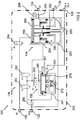
- Fig. 4 shows a device 120 for controlling the brake system according to an embodiment of the present invention.
- device 120 may be an embodiment of the invention Fig. 1 act described device.
- the device 120 corresponds to that of FIG Fig. 2 with the difference that a feedback valve 466 is connected between the fourth trailer control valve port 254 and the second parking brake control valve port 242.
- the feedback valve 466 is designed as a solenoid valve in the form of a 2/2-way valve.
- the third 2/2-way valve 263 and the feedback valve 466 disconnect the control line of the trailer control valve 134 from the control line of the parking brake control valve 132.
- the valves 261, 262, 263 of the valve device 136 for example, from the in Fig. 1 be called accordingly controlled electronic control device.
- device 120 is provided for trucks with a parking strategy in which the brake of the trailer is activated when the parking brake of the towing vehicle is activated.
- Fig. 5 shows a device 120 for controlling the brake system according to an embodiment of the present invention.
- device 120 may be an embodiment of the invention Fig. 1 act described device.
- the device 120 corresponds to that of FIG Fig. 3 described device, with the difference that the feedback valve 466, as shown by Fig. 5 is connected between the second parking brake control valve port 242 and the third parking brake valve port 243 is connected.
- the third 2/2-way valve 263 opens the connection to the control line of the parking brake control valve 132.
- the valves 261, 262, 263 of the valve device 136 for example, from the in Fig. 1 be called accordingly controlled electronic control device.
- device 120 is provided for trucks with a parking strategy in which an activation of the parking brake of the towing vehicle does not lead to an activation of the brake of the trailer.
- the 466 feedback valve is not necessary for the safe venting of leaks.
- By omitting the feedback valve 466 results for the application of Volvotrucks according to an embodiment of in Fig. 3 shown scheme.
- control pressure for the parking brake control valve 132 (PBRV) and the control pressure for the TCM parking brake function are generated by the functional unit EPB.
- the control unit TCM generates the control pressure for the function of the electric brake.
- a piston, namely the parking brake piston 280 in the TCM is designed with a double use.
- a parking brake piston 280 for the parking function of the TCM and the other as a parking brake piston 280 for the electrical braking of the TCM.
- the total number of solenoid valves 261, 262, 263, 264 can be kept low.
- the use of the parking brake piston 280 twice for parking brake function and electric braking requires only a few pistons.
- a common electronic unit offers cost savings compared to two electronic units.
- pressure sensors 267, 268 in the EPB part and in the TCM part are used according to an exemplary embodiment to mutually plausibility the correct sensor function.
- TCM components can be designed easily.
- the TCM functionality can be implemented to save space.
- an integration of EPB housing and TCM housing can be realized. This eliminates lines and fittings between otherwise separate housings for EPB and TCM.
- a common control pressure generation for EPB and TCM is realized using two 2/2 solenoid valves 261, 263, a 3/2 solenoid valve and a proportional valve.
- a feedback of the EPB (spring store to control line PBRV) takes place.
- the feedback is switched and only available if there is no pressure regulation.
- the feedback is designed as a throttle in the EPB piston.
Description
Die vorliegende Erfindung bezieht sich auf eine Vorrichtung zum Steuern einer Bremsanlage für ein Nutzfahrzeug und auf eine Bremsanlage.The present invention relates to a device for controlling a brake system for a commercial vehicle and to a brake system.
Eine Bremsanlage eines Nutzfahrzeugs umfasst eine elektronische Parkbremse (EPB) und ein Anhängersteuermodul (TCM).A commercial vehicle brake system includes an electronic parking brake (EPB) and a trailer control module (TCM).
Die
Es ist die Aufgabe der vorliegenden Erfindung eine verbesserte Vorrichtung zum Steuern einer Bremsanlage für ein Nutzfahrzeug und eine verbesserte Bremsanlage zu schaffen.It is the object of the present invention to provide an improved device for controlling a brake system for a commercial vehicle and an improved brake system.
Diese Aufgabe wird durch eine Vorrichtung zum Steuern einer Bremsanlage für ein Nutzfahrzeug und eine Bremsanlage gemäß den Hauptansprüchen gelöst.This object is achieved by a device for controlling a brake system for a commercial vehicle and a brake system according to the main claims.
Der beschriebene Ansatz basiert auf einer Integration der Funktionseinheiten der elektronischen Parkbremse und des Anhängersteuermoduls. Dabei wird eine Doppelnutzung eines Parkbremskolbens eines Anhängersteuerventils umgesetzt. Dies ermöglicht die Bereitstellung einer Funktion des elektrischen Bremsens als die Bereitstellung einer Parkbremsfunktion über den Parkbremskolben.The described approach is based on an integration of the functional units of the electronic parking brake and the trailer control module. In this case, a double use of a parking brake piston of a trailer control valve is implemented. This makes it possible to provide a function of electric braking as the provision of a parking brake function via the parking brake piston.
Im Folgenden werden zunächst die grundsätzlichen Funktionen der elektronischen Parkbremse (EPB) und des Anhängersteuermoduls (TCM) beschrieben.In the following, the basic functions of the electronic parking brake (EPB) and the trailer control module (TCM) will first be described.
Ein von einer HCU (Hand-Control Unit) elektronisch erfasster und als elektronisches Signal übermittelter Fahrerwunsch oder automatisch generierter Soll-Betriebszustand der Parkbremse ist umzusetzen. Im EPB-Modul wird der Soll-Betriebszustand mit der elektronischen Steuereinheit unter Nutzung von Magnetventilen, Drucksensoren und pneumatischen Ventilen dazu genutzt die Parkbremsaktuatoren (Federspeicherbremszylinder) pneumatisch zu betätigen oder zu lösen. In der Parkstellung ist der Federspeicher entlüftet und in der Fahrstellung ist der Federspeicher mit Druckluft beaufschlagt. Sowohl die Parkstellung als auch die Fahrstellung müssen auch bei Stromausfall stabil bleiben. Die Federspeicher können auch gestuft mit Druckluft beaufschlagt werden, um z.B. eine Hilfsbremswirkung zu erzielen, insbesondere im Falle eines Ausfalls der Betriebsbremse. Das Anhängersteuermodul kann von der elektronischen Parkbremse angesteuert werden, um gegebenenfalls die Betriebsbremse des Anhängers zu aktivieren. Dabei gibt es zwei Varianten. In der ersten Variante ist der Anhänger in der stabilen Parkstellung gebremst. In der zweiten Variante ist der Anhänger in der stabilen Parkstellung ungebremst.One of a HCU (Hand Control Unit) electronically detected and transmitted as an electronic signal driver request or automatically generated desired operating state of the parking brake is implemented. In the EPB module, the desired operating state with the electronic control unit using solenoid valves, pressure sensors and pneumatic valves is used to the parking brake actuators (spring brake cylinder) pneumatically operated or released. In the parking position of the spring accumulator is vented and in the driving position of the spring accumulator is pressurized with compressed air. Both the parking position and the driving position must remain stable even in the event of a power failure. The Spring accumulator can also be supplied stepped with compressed air, for example, to achieve an auxiliary braking effect, especially in the event of a failure of the service brake. The trailer control module can be controlled by the electronic parking brake to optionally activate the service brake of the trailer. There are two variants. In the first variant, the trailer is braked in the stable parking position. In the second variant, the trailer is unbraked in the stable parking position.
Das Anhängersteuermodul ist ein Modul eines EBS (elektronischen Bremssystems). Es setzt Anhänger-Solldruck-Vorgaben eines EBS-Systems und einer Parkbremse in den pneumatischen Steuerdruck zum Abbremsen des Anhängers um und gibt ihn über die gelbe Bremsleitung zum Anhänger aus (nachfolgend "Druck zum Anhänger" genannt). Im normalen Fahrbetrieb regelt ein elektronisches Steuergerät (z.B. EBS-ECU) den Druck zum Anhänger mittels Drucksensor, Magnetventilen und Relaisteil. Für den Fall eines Fehlers in der elektrischen Druckregelung (Back Up) wird der Druck zum Anhänger mit rein pneumatischen Mitteln aus dem pneumatischen Backupdruck vom Fußbremsventil gesteuert, der im Normalfall (bei elektronischer Druckregelung) zurückgehalten wird, z.B. mit einem Backup-Magnetventil. Auch die Parkbremse (z.B. eine EPB) gibt dem TCM ein Steuersignal für den Druck zum Anhänger vor, jedoch invertiert. Im Falle eines Abrisses der pneumatischen Bremsleitung zum Anhänger entlüftet das Anhängersteuermodul bei einer Vollbremsung die (rote) Vorratsleitung zum Anhänger, worauf dieser automatisch einbremst.The trailer control module is a module of an EBS (Electronic Braking System). It converts trailer target pressure specifications of an EBS system and a parking brake into the pneumatic control pressure for braking the trailer and outputs it to the trailer via the yellow brake line (hereinafter referred to as "pressure to the trailer"). During normal driving, an electronic control unit (e.g., EBS-ECU) controls the pressure to the trailer via the pressure sensor, solenoid valves, and relay part. In the event of a fault in the electrical pressure control (Back Up), the pressure to the trailer is controlled by pneumatic pressure from the pneumatic backup pressure from the foot brake valve, which is normally retained (with electronic pressure control), e.g. with a backup solenoid valve. The parking brake (e.g., EPB) also provides the TCM with a control signal for pushing to the trailer, but inverted. In the event of a break in the pneumatic brake line to the trailer, the trailer control module vents the (red) supply line to the trailer during an emergency stop, whereupon it automatically brakes.
Die Funktionen der elektronischen Parkbremse (EPB) und des Anhängersteuermoduls (TCM) können in eine Vorrichtung zum Steuern einer Bremsanlage für ein Nutzfahrzeug integriert werden.The functions of the electronic parking brake (EPB) and the trailer control module (TCM) can be integrated into a device for controlling a brake system for a commercial vehicle.
Eine solche Vorrichtung zum Steuern einer Bremsanlage für ein Nutzfahrzeug weist die folgenden Merkmale auf:
- einen Versorgungsanschluss zum Bereitstellen von Druckluft, einen Betriebsbremsanschluss zum Koppeln der Vorrichtung mit einem Kupplungskopf für eine Anhänger-Bremsleitung eines Anhängers des Nutzfahrzeugs, einen Vorratsanschluss zum Koppeln der Vorrichtung mit einem Kupplungskopf für eine Anhängerversorgung des Anhängers und einen Parkbremsanschluss zum Koppeln der Vorrichtung mit einer Parkbremse des Nutzfahrzeugs;
- ein Parkbremssteuerventil zum Bereitstellen einer Parkbremsfunktion für das Nutzfahrzeug, wobei das Parkbremssteuerventil einen ersten Parkbremssteuerventilanschluss, einen zweiten Parkbremssteuerventilanschluss und einen dritten Parkbremssteuerventilanschluss aufweist, wobei der erste Parkbremssteuerventilanschluss mit dem Versorgungsanschluss und der zweite Parkbremssteuerventilanschluss mit dem Parkbremsanschluss verbunden sind;
- ein Anhängersteuerventil zum Bereitstellen einer Feststellbremsfunktion und einer Funktion des elektrischen Bremsens für den Anhänger, wobei das Anhängersteuerventil einen ersten Anhängersteuerventilanschluss, einen zweiten Anhängersteuerventilanschluss, einen dritten Anhängersteuerventilanschluss und einen vierten Anhängersteuerventilanschluss aufweist, wobei der erste Anhängersteuerventilanschluss mit dem Versorgungsanschluss, der zweite Anhängersteuerventilanschluss mit dem Betriebsbremsanschluss und der dritte Anhängersteuerventilanschluss mit dem Vorratsanschluss verbunden ist, und wobei das Anhängersteuerventil einen Parkbremskolben aufweist, der verschiebbar angeordnet ist, um abhängig von einem Belüftungszustand des vierten Anhängersteuerventilanschluss eine Belüftung des zweiten Anhängersteuerventilanschlusses über den ersten Anhängersteuerventilanschluss zum Bereitstellen der Feststellbremsfunktion und der Funktion des elektrischen Bremsens zu steuern; und
- eine schaltbare Ventileinrichtung zum schaltbaren Verbinden des Versorgungsanschluss mit dem dem dritten Parkbremssteuerventilanschluss und/oder dem vierten Anhängersteuerventilanschluss, um das Bereitstellen der Parkbremsfunktion für das Nutzfahrzeug sowie das Bereitstellen der Feststellbremsfunktion und der Funktion des elektrischen Bremsens für den Anhänger zu bewirken.
- a supply port for providing compressed air, a service brake port for coupling the device to a trailer brake hose trailer coupling head of the utility vehicle, a supply port for coupling the device to a trailer trailer hitch coupling head, and a park brake port for coupling the device to a parking brake the commercial vehicle;
- a parking brake control valve for providing a parking brake function to the utility vehicle, the parking brake control valve having a first parking brake control valve port, a second parking brake control valve port and a third parking brake control valve port, the first parking brake control valve port being connected to the supply port and the second parking brake control valve port being connected to the parking brake port;
- a trailer control valve for providing a parking brake function and an electric braking function for the trailer, the trailer control valve having a first trailer control valve port, a second trailer control valve port, a third trailer control valve port and a fourth trailer control valve port, the first trailer control valve port to the supply port, the second trailer control valve port to the service brake port and the trailer control valve is connected to the supply port, and wherein the trailer control valve has a parking brake piston slidably disposed to ventilate the second trailer control valve port via the first trailer control valve port to provide the parking brake function and the electric braking function depending on a ventilation state of the fourth trailer control valve port to control; and
- a switchable valve means for switchably connecting the supply port to the third parking brake control valve port and / or the fourth trailer control valve port to effect provision of the parking brake function to the utility vehicle and providing the parking brake function and the electric braking function to the trailer.
Das Parkbremssteuerventil kann der Funktionseinheit der elektronischen Parkbremse (EPB) und das Anhängersteuerventil kann der Funktionseinheit des Anhängersteuermoduls (TCM) zugeordnet werden. Die Parkbremsfunktion kann zum Feststellen und Lösen der Parkbremse des Nutzfahrzeugs verwendet werden. Die Feststellbremsfunktion kann entsprechend zu der Parkbremsfunktion zum Feststellen und Lösen einer Bremse des Anhängers verwendet werden. Die Funktion des elektrischen Bremsens kann zum Aktivieren und Lösen einer Bremse des Anhängers verwendet werden, beispielsweise gesteuert von einem elektronischen Steuergerät zum Regeln einer Antiblockierfunktion (ABS-Steuergerät). Die Ventileinrichtung kann zumindest einen Steuereingang zum Empfangen zumindest eines elektronischen Steuersignals umfassen. Die Ventileinrichtung kann sowohl zum Generieren eines Steuerdrucks zum Steuern des Parkbremssteuerventils als auch zum Generieren eines Steuerdrucks zum Steuern des Anhängersteuerventils verwendet werden. Somit kann die Ventileinrichtung den beiden Funktionseinheiten EPB und TCM zugeordnet werden. Die Ventileinrichtung kann beispielsweise zwei 2/2-Wege-Magentventile umfassen, über die ein über den Versorgungsanschluss bereitgestellter Druck als Steuerdruck an einen Steueranschluss des Parkbremssteuerventils und des Anhängersteuerventils weitergeleitet werden kann. Aufgrund einer Doppelfunktion des Parkbremskolbens des Anhängersteuerventils kann der vierte Anhängersteuerventilanschluss des Anhängersteuerventils als einziger Steueranschluss des Anhängersteuerventils vorgesehen sein, der unter Verwendung des von dem Versorgungsanschluss bereitgestellten Drucks angesteuert wird.The parking brake control valve may be associated with the electronic parking brake (EPB) functional unit and the trailer control valve may be associated with the trailer control module (TCM) functional unit. The parking brake function can be used to detect and release the parking brake of the utility vehicle. The parking brake function may be used in accordance with the parking brake function for detecting and releasing a brake of the trailer. The function of the electric brake can be used to activate and release a brake of the trailer, for example, controlled by an electronic control unit for controlling an anti-lock function (ABS-control unit). The valve device may comprise at least one control input for receiving at least one electronic control signal. The valve device may be used both for generating a control pressure for controlling the parking brake control valve and for generating a control pressure for controlling the trailer control valve. Thus, the valve device can be assigned to the two functional units EPB and TCM. The valve device may, for example, comprise two 2/2-way magent valves, via which a pressure provided via the supply connection can be forwarded as control pressure to a control connection of the parking brake control valve and the trailer control valve. Due to a dual function of the parking brake piston of the trailer control valve, the trailer control valve fourth trailer control valve port may be provided as a single control port of the trailer control valve that is controlled using the pressure provided by the supply port.
Gemäß einer Ausführungsform kann die Ventileinrichtung ausgebildet sein, um in einer ersten Ventilstellung den Versorgungsanschluss von dem dritten Parkbremssteuerventilanschluss und dem vierten Anhängersteuerventilanschluss zu trennen. In einer zweiten Ventilstellung kann die Ventileinrichtung ausgebildet sein, um den Versorgungsanschluss von dem dritten Parkbremssteuerventilanschluss zu trennen und mit dem vierten Anhängersteuerventilanschluss zu verbinden. In einer dritten Ventilstellung kann die Ventileinrichtung ausgebildet sein, um den Versorgungsanschluss mit dem dritten Parkbremssteuerventilanschluss und dem vierten Anhängersteuerventilanschluss zu verbinden. Diese drei Schaltstellungen können ausreichend sein, um unter Verwendung des Parkbremssteuerventils und des Anhängersteuerventils die Parkbremsfunktion des Nutzfahrzeugs sowie die Feststellbremsfunktion und die Funktion des elektrischen Bremsens des Anhängers umzusetzen.According to one embodiment, the valve device may be configured to disconnect the supply connection from the third parking brake control valve connection and the fourth trailer control valve connection in a first valve position. In a second valve position, the valve means may be configured to disconnect the supply port from the third parking brake control valve port and connect to the fourth trailer control valve port. In a third valve position, the valve means may be configured to connect the supply port to the third parking brake control valve port and the fourth trailer control valve port. These three switch positions may be sufficient to implement the parking brake function of the utility vehicle as well as the parking brake function and the electric brake function of the trailer using the parking brake control valve and the trailer control valve.
Das Parkbremssteuerventil kann ausgebildet sein, um den zweiten Parkbremssteuerventilanschluss mit dem ersten Parkbremssteuerventilanschluss zu verbinden, wenn der dritte Parkbremssteuerventilanschluss belüftet ist, und ausgebildet sein, um den zweiten Parkbremssteuerventilanschluss von dem ersten Parkbremssteuerventilanschluss zu trennen, wenn der dritte Parkbremssteuerventilanschluss entlüftet ist. Vorteilhafterweise kann dazu ein Parkbremssteuerventil eingesetzt werden, wie es bereits bei bekannten EPB-Modulen eingesetzt wird.The parking brake control valve may be configured to connect the second parking brake control valve port to the first parking brake control valve port when the third parking brake control valve port is vented and configured to disconnect the second parking brake control valve port from the first parking brake control valve port when the third parking brake control port port is vented. Advantageously, a parking brake control valve can be used for this, as it is already used in known EPB modules.
Der Parkbremskolben des Anhängersteuerventils kann verschiebbar angeordnet sein, um ansprechend auf eine Entlüftung des vierten Anhängersteuerventilanschlusses in eine erste Endstellung bewegt zu werden, wodurch der Parkbremskolben von einem Ventilsitz abgehoben wird. Dies kann bewirken, dass der erste Anhängersteuerventilanschluss mit dem zweiten Anhängersteuerventilanschluss fluidisch verbunden wird. Ansprechend auf eine Belüftung des vierten Anhängersteuerventilanschlusses kann der Parkbremskolben in eine zweite Endstellung bewegt werden, wodurch der Parkbremskolben an dem Ventilsitz anliegt. Dies kann bewirken, dass der erste Anhängersteuerventilanschluss von dem zweiten Anhängersteuerventilanschluss getrennt wird. Vorteilhafterweise können die Endstellungen des Parkbremskolbens sowohl zum Umsetzen der Feststellbremsfunktion als auch zum Umsetzen der Funktion des elektrischen Bremsens des Anhängers verwendet werden.The park brake piston of the trailer control valve may be slidably disposed to be moved to a first end position in response to venting of the fourth trailer control valve port, thereby lifting the park brake piston from a valve seat. This may cause the first trailer control valve port to be fluidly connected to the second trailer control valve port. In response to venting of the fourth trailer control valve port, the parking brake piston may be moved to a second end position whereby the parking brake piston rests against the valve seat. This may cause the first trailer control valve port to be disconnected from the second trailer control valve port. Advantageously, the end positions of the parking brake piston can be used both for implementing the parking brake function and for implementing the function of the electric braking of the trailer.
Gemäß einer Ausführungsform umfasst die Vorrichtung einen Steueranschluss zum Koppeln der Vorrichtung mit einem Fußbremsventil. Dazu kann das Anhängersteuerventil einen fünften Anhängersteuerventilanschluss aufweisen, der mit dem Steueranschluss gekoppelt ist. Ferner kann das Anhängersteuerventil einen Kolben aufweisen, der verschiebbar angeordnet ist, um ansprechend auf eine Belüftung des fünften Anhängersteuerventilanschlusses gegen eine Federkraft in Richtung des Ventilsitzes bewegt zu werden und gegen den Ventilsitz zu drücken. Dadurch kann der Ventilsitz verschoben werden, sodass der erste Anhängersteuerventilanschluss mit dem zweiten Anhängersteuerventilanschluss fluidisch verbunden wird. Auf diese Weise kann die Bremse des Anhängers zusätzlich über eine Betätigung eines Fußbremspedals aktiviert werden.In one embodiment, the device includes a control port for coupling the device to a foot brake valve. For this purpose, the trailer control valve may have a fifth trailer control valve port, which is coupled to the control port. Further, the trailer control valve may include a piston slidably disposed to be moved against a spring force toward the valve seat in response to venting of the fifth trailer control valve port and to urge against the valve seat. Thereby, the valve seat can be displaced so that the first trailer control valve port is fluidically connected to the second trailer control valve port. In this way, the brake of the trailer can be additionally activated via an operation of a Fußbremspedals.
Vorteilhafterweise kann das Anhängersteuerventil neben dem vierten Anhängersteuerventilanschluss und dem fünften Anhängersteuerventilanschluss keinen weiteren Steueranschluss aufweisen. Auf diese Weise kann das Anhängersteuerventil sehr kompakt gebaut sein.Advantageously, the trailer control valve in addition to the fourth trailer control valve port and the fifth trailer control valve port can have no further control port. In this way, the trailer control valve can be built very compact.
Die Vorrichtung kann ein eine Gehäusewand aufweisendes Gehäuse umfassen. Dabei kann die Gehäusewand das Parkbremssteuerventil, das Anhängersteuerventil und die Ventileinrichtung umschließen und den Betriebsbremsanschluss, den Vorratsanschluss und den Parkbremsanschluss aufweisen. Somit können die Funktionseinheiten EPB und TCM in einem einzigen Gehäuse integriert angeordnet sein.The device may comprise a housing wall having a housing. In this case, the housing wall may enclose the parking brake control valve, the trailer control valve and the valve device and have the service brake connection, the supply connection and the parking brake connection. Thus, the functional units EPB and TCM can be arranged integrated in a single housing.
Gemäß einer Ausführungsform kann die Ventileinrichtung ein erstes 2/2-Wegeventil aufweisen, wobei ein erster Anschluss des ersten 2/2-Wegeventils mit dem Versorgungsanschluss und ein zweiter Anschluss des ersten 2/2-Wegeventils mit dem vierten Anhängersteuerventilanschluss verbunden ist, ein zweites 2/2-Wegeventil aufweisen, wobei ein erster Anschluss des zweiten 2/2-Wegeventils mit dem vierten Anhängersteuerventilanschluss und ein zweiter Anschluss des zweiten 2/2-Wegeventils mit einer Entlüftung verbunden ist, und ein drittes 2/2-Wegeventil aufweisen, wobei ein erster Anschluss des dritten 2/2-Wegeventils mit dem vierten Anhängersteuerventilanschluss und ein zweiter Anschluss des dritten 2/2-Wegeventils mit dem dritten Parkbremssteuerventilanschluss verbunden ist. Auf diese Weise können drei 2/2-Wegeventile, die beispielsweise als Magnetventile realisiert sein können, ausreichend sein, um die erforderlichen Funktionen der Ventileinrichtung umzusetzen. Anstelle eines 2/2-Wegeventils können andere Ventilformen eingesetzt werden, durch die die Funktion eines 2/2-Wegeventils nachgebildet werden kann.According to one embodiment, the valve device may include a first 2/2-way valve, wherein a first port of the first 2/2-way valve is connected to the supply port and a second port of the first 2/2-way valve is connected to the fourth trailer control valve port, a second 2 / 2-way valve, wherein a first port of the second 2/2-way valve with the fourth trailer control valve port and a second port of the second 2/2-way valve is connected to a vent, and a third 2/2-way valve, wherein a first port of the third 2/2-way valve is connected to the fourth trailer control valve port and a second port of the third 2/2-way valve is connected to the third parking brake control valve port. In this way, three 2/2-way valves, which may for example be realized as solenoid valves, be sufficient to implement the required functions of the valve device. Instead of a 2/2-way valve other valve shapes can be used, by which the function of a 2/2-way valve can be modeled.
Vorteilhafterweise können die 2/2-Wegeventile ansteuerbar sein, um das Bereitstellen der Parkbremsfunktion durch das Parkbremssteuerventil sowie das Bereitstellen der Feststellbremsfunktion, der Funktion des elektrischen Bremsens durch das Anhängersteuerventil zu bewirken. Somit können die drei 2/2-Wegeventile ausreichend sein, um die genannten Funktionen umzusetzen. Auf diese Weise kann die Ventileinrichtung mit sehr wenigen 2/2-Wegeventilen umgesetzt werden.Advantageously, the 2/2-way valves may be controllable to effect the provision of the parking brake function by the parking brake control valve and the provision of the parking brake function, the function of electric braking by the trailer control valve. Thus, the three 2/2-way valves may be sufficient to implement the said functions. In this way, the valve device can be implemented with very few 2/2-way valves.
Gemäß einer Ausführungsform kann die Ventileinrichtung ein viertes 2/2-Wegeventil aufweisen, wobei ein erster Anschluss des vierten 2/2-Wegeventils mit dem zweiten Parkbremssteuerventilanschluss und ein zweiter Anschluss des vierten 2/2-Wegeventils mit dem dritten Parkbremssteuerventilanschluss verbunden ist. Dies ermöglicht eine Rücckopplung zwischen dem zweiten und dem dritten Parkbremssteuerventilanschluss.According to one embodiment, the valve device may comprise a fourth 2/2-way valve, wherein a first port of the fourth 2/2-way valve with the second parking brake control valve port and a second port of the fourth 2/2-way valve is connected to the third parking brake control valve port. This allows a back-coupling between the second and the third parking brake control valve connection.
Eine Bremsanlage für ein Nutzfahrzeug weist die folgenden Merkmale auf:
- eine genannte Vorrichtung zum Steuern einer Bremsanlage für ein Nutzfahrzeug;
- eine Druckluftversorgung, die über den Versorgungsanschluss mit der Vorrichtung verbunden ist, einen Kupplungskopf für eine Anhänger-Bremsleitung, der über den Betriebsbremsanschluss mit der Vorrichtung verbunden ist, einen Kupplungskopf für eine Anhängerversorgung, der über den Vorratsanschluss mit der Vorrichtung verbunden ist und eine Parkbremse, die über den Parkbremsanschluss mit der Vorrichtung verbunden ist; und
- eine elektronische Steuereinrichtung, die ausgebildet ist, um zumindest ein Steuersignal an zumindest einen Steuereingang der Ventileinrichtung bereitzustellen.
- a said device for controlling a brake system for a commercial vehicle;
- a compressed air supply connected to the device via the supply port, a trailer brake pipe coupling head connected to the device via the service brake port, a trailer supply coupling head, which is connected via the supply terminal to the device and a parking brake, which is connected via the parking brake connection with the device; and
- an electronic control device which is designed to provide at least one control signal to at least one control input of the valve device.
Die elektronische Steuereinrichtung kann ausgebildet sein, um das Bereitstellen der Parkbremsfunktion durch das Parkbremssteuerventil sowie das Bereitstellen der Feststellbremsfunktion und der Funktion des elektrischen Bremsens durch das Anhängersteuerventil durch Ausgabe eines oder mehrere Steuersignale an den zumindest einen Steuereingang der Ventileinrichtung zu bewirken.The electronic control device may be configured to effect the provision of the parking brake function by the parking brake control valve and the provision of the parking brake function and the electric braking function by the trailer control valve by outputting one or more control signals to the at least one control input of the valve device.
Bevorzugte Ausführungsbeispiele der vorliegenden Erfindung werden nachfolgend Bezug nehmend auf die beiliegenden Zeichnungen näher erläutert. Es zeigen:
- Fig. 1
- eine schematische Darstellung einer Bremsanlage für ein Nutzfahrzeug;
- Fig. 2
- eine Darstellung einer Vorrichtung zum Steuern einer Bremsanlage;
- Fig. 3
- eine Darstellung einer Vorrichtung zum Steuern einer Bremsanlage;
- Fig. 4
- eine Darstellung einer Vorrichtung zum Steuern einer Bremsanlage; und
- Fig. 5
- eine Darstellung einer Vorrichtung zum Steuern einer Bremsanlage.
- Fig. 1
- a schematic representation of a brake system for a commercial vehicle;
- Fig. 2
- an illustration of an apparatus for controlling a brake system;
- Fig. 3
- an illustration of an apparatus for controlling a brake system;
- Fig. 4
- an illustration of an apparatus for controlling a brake system; and
- Fig. 5
- an illustration of a device for controlling a brake system.
In der nachfolgenden Beschreibung der bevorzugten Ausführungsbeispiele der vorliegenden Erfindung werden für die in den verschiedenen Zeichnungen dargestellten und ähnlich wirkenden Elemente gleiche oder ähnliche Bezugszeichen verwendet, wobei eine wiederholte Beschreibung dieser Elemente weggelassen wird.In the following description of the preferred embodiments of the present invention, the same or similar reference numerals are used for the elements shown in the various drawings and similar, and a repeated description of these elements will be omitted.
Die Vorrichtung 120 weist einen Versorgungsanschluss 122, einen Betriebsbremsanschluss 124, einen Vorratsanschluss 126, einen Parkbremsanschluss 128 und einen Steueranschluss 130 auf. Die Druckluftversorgung 112 ist über den Versorgungsanschluss 122, der Kupplungskopf 114 über den Betriebsbremsanschluss 124, der Kupplungskopf 116 über den Vorratsanschluss 126, die Parkbremse 118 über den Parkbremsanschluss 128 und das Fußbremsventil 110 ist über den Steueranschluss 130 mit der Vorrichtung 120 gekoppelt, beispielsweise über pneumatische Leitungen.The
Die Vorrichtung 120 weist ein Parkbremssteuerventil 132, ein Anhängersteuerventil 134 und eine schaltbare Ventileinrichtung 136 auf. Die Vorrichtung 120 umfasst die Funktionseinheiten einer elektrischen Parkbremse sowie eines Anhängersteuermoduls. Insbesondere ist die Vorrichtung 120 ausgebildet, um eine Parkbremsfunktion für das Nutzfahrzeug 100 sowie eine Feststellbremsfunktion und eine Funktion des elektrischen Bremsens für den Anhänger 102 bereitzustellen. Dazu weist die Bremsanlage eine elektronische Steuereinrichtung 138 auf, die ausgebildet ist, um zumindest ein Steuersignal an zumindest einen Steuereingang der Ventileinrichtung 136 bereitzustellen. Die elektronische Steuereinrichtung 138 kann auch in die Vorrichtung 120 integriert sein. Die Ventileinrichtung 136 ist ausgebildet, um gesteuert über das zumindest eine Steuersignal den Versorgungsanschluss 122 mit einem Steueranschluss des Parkbremssteuerventils 132 und/oder einem Steueranschluss des Anhängersteuerventils 134 zu verbinden oder den Versorgungsanschluss 122 von dem Steueranschluss des Parkbremssteuerventils 132 und/oder dem Steueranschluss des Anhängersteuerventils 134 zu trennen. Abhängig von einer durch das zumindest eine Steuersignal bewirkten Schaltstellung der Ventileinrichtung 136 ist das Parkbremssteuerventil 132 ausgebildet, um die Parkbremsfunktion bereitzustellen, durch die die Parkbremse 118 aktiviert wird. Entsprechend ist das Anhängersteuerventil 134 abhängig von einer durch das zumindest eine Steuersignal bewirkten Schaltstellung der Ventileinrichtung 136 ausgebildet, um die Feststellbremsfunktion oder die Funktion des elektrischen Bremsens bereitzustellen, durch die eine Bremse 140 des Anhängers 102 aktiviert werden kann.The
Das Anhängersteuerventil 134 weist einen Parkbremskolben auf, der abhängig von einem Belüftungszustand eines Steueranschlusses des Anhängersteuerventils 134 zwischen einer ersten Stellung und einer zweiten Stellung bewegt werden kann. Abhängig von der Stellung des Parkbremskolbens wird der Versorgungsanschluss 122 mit dem Betriebsbremsanschluss 124 verbunden oder von dem Betriebsbremsanschluss 124 getrennt. Der gemäß einem Ausführungsbeispiel ausschließlich über den einen Steueranschluss des Anhängersteuerventils 134 steuerbaren Parkbremskolben wird sowohl die Feststellbremsfunktion als auch die Funktion des elektrischen Bremsens bereitgestellt.The
Gemäß einem Ausführungsbeispiel weist das Anhängersteuerventil 134 nur einen einzigen Steueranschluss auf, der mit über den Versorgungsanschluss 122 bereitgestellter Druckluft angesteuert wird.According to one embodiment, the
Die Vorrichtung 120 weist als eingangseitige Anschlüsse den Versorgungsanschluss 122 und den Steueranschluss 130 und als ausgangsseitige Anschlüsse den Betriebsbremsanschluss 124, den Vorratsanschluss 126 und den Parkbremsanschluss 128 auf.The
Die Vorrichtung 120 weist ein Parkbremssteuerventil 132, ein Anhängersteuerventil 134 und eine schaltbare Ventileinrichtung 136 auf. Als Funktionseinheiten umfasst die Vorrichtung das Parkbremssteuerventil 132, das Anhängersteuerventil 134 und die Ventileinrichtung 136.The
Die Vorrichtung 120 weist gemäß einem Ausführungsbeispiel ein Gehäuse 220 auf, wobei die Anschlüsse 122, 124, 126, 128, 130 in eine das Parkbremssteuerventil 132, das Anhängersteuerventil 134 und die Ventileinrichtung 136 umschließende Gehäusewand des Gehäuses 220 integriert sind.The
Das Parkbremssteuerventil 132 weist einen ersten Parkbremssteuerventilanschluss 241, einen zweiten Parkbremssteuerventilanschluss 242 und einen dritten Parkbremssteuerventilanschluss 243 auf.The parking
Das Anhängersteuerventil 134 weist einen ersten Anhängersteuerventilanschluss 251, einen zweiten Anhängersteuerventilanschluss 252, einen dritten Anhängersteuerventilanschluss 253, einen vierten Anhängersteuerventilanschluss 254 und einen fünften Anhängersteuerventilanschluss 255 auf.The
Die Ventileinrichtung 136 weist vier 2/2-Wegeventile 261, 262, 263 und gemäß diesem Ausführungsbeispiel ein 3/2-Wegeventil 264 auf. Die Ventile 261, 262, 263, 264 sind als Magnetventile ausgeführt.The
Der erste Parkbremssteuerventilanschluss 241 des Parkbremssteuerventils 132 ist über ein Rückschlagventil 266 mit dem Versorgungsanschluss verbunden. Der zweite Parkbremssteuerventilanschluss 242 ist mit dem Parkbremsanschluss 128 verbunden. Eine Druckmesseinrichtung 267 ist mit einer den zweiten Parkbremssteuerventilanschluss 242 und den Parkbremsanschluss 128 verbindenden Leitung gekoppelt, um an dem zweiten Parkbremssteuerventilanschluss 242 herrschenden Druck erfassen zu können. Der dritte Parkbremssteuerventilanschluss 243 ist über ein erstes 2/2-Wegeventil 261 und ein drittes 2/2-Wegeventil 263 der Ventileinrichtung 136 sowie über das Rückschlagventil 266 mit dem Versorgungsanschluss 122 verbunden.The first parking brake
Dabei ist ein erster Anschluss des ersten 2/2-Wegeventils 261 mit dem Rückschlagventil 266 und ein zweiter Anschluss des ersten 2/2-Wegeventils 261 mit einem ersten Anschluss des zweiten 2/2-Wegeventils 262, einem ersten Anschluss des dritten 2/2-Wegeventils 263 sowie mit dem vierten Anhängersteuerventilanschluss 254 verbunden. Ein zweiter Anschluss des zweiten 2/2-Wegeventils 262 ist offen und ein zweiter Anschluss des dritten 2/2-Wegeventils 263 ist mit dem dritten Parkbremssteuerventilanschluss verbunden. Das 3/2-Wegeventil 264 ist zwischen dem Steueranschluss 130 und dem fünften Anhängersteuerventilanschluss 255 geschaltet.In this case, a first connection of the first 2/2-
Der Versorgungsanschluss 122 ist mit dem ersten Anhängersteuerventilanschluss 251 verbunden. Der zweite Anhängersteuerventilanschluss 252 ist mit dem Betriebsbremsanschluss 124 verbunden, wobei eine weitere Druckmesseinrichtung 268 mit einer den zweiten Anhängersteuerventilanschluss 252 und den Betriebsbremsanschluss 124 verbindenden Leitung gekoppelt ist, um einen an dem zweiten Anhängersteuerventilanschluss 252 herrschenden Druck erfassen zu können. Der dritte Anhängersteuerventilanschluss 253 ist mit dem Vorratsanschluss 126 verbunden.The
Das Parkbremssteuerventil 132 ist ausgebildet, um den zweiten Parkbremssteuerventilanschluss 242 mit dem ersten Parkbremssteuerventilanschluss 241 zu verbinden, wenn der dritte Parkbremssteuerventilanschluss 243 belüftet ist. Wenn der dritte Parkbremssteuerventilanschluss 243 entlüftet ist, ist das Parkbremssteuerventil 132 ausgebildet, um den zweiten Parkbremssteuerventilanschluss 242 von dem ersten Parkbremssteuerventilanschluss 241 zu trennen. Dazu weist das Parkbremssteuerventil 132 gemäß diesem Ausführungsbeispiel einen Kolben 270 auf der zwischen einer ersten und einer zweiten Stellung bewegbar angeordnet ist. Der Kolben 270 wird bei entlüftetem dritten Parkbremssteuerventilanschluss 243 durch eine Feder gegen den dritten Parkbremssteuerventilanschluss 243 gedrückt. In dieser ersten Stellung des Kolbens 270 wird eine Verbindungsöffnung zwischen dem ersten Parkbremssteuerventilanschluss 241 und dem zweiten Parkbremssteuerventilanschluss 242 über einen weiteren Kolben 272 verschlossen. Der weitere Kolben 272 weist eine Durchgangsöffnung auf, über die der zweite Parkbremssteuerventilanschluss 242 mit einer Entlüftungsöffnung des Parkbremssteuerventils 132 verbunden ist, wenn sich der Kolben 270 in der ersten Stellung befindet. Wird der dritte Parkbremssteuerventilanschluss 243 belüftet, so wird der Kolben 270 entgegen der Federkraft der Feder in die zweite Stellung bewegt und drückt dabei gegen den weiteren Kolben 272. Der weitere Kolben 272 wird durch den Druck des Kolbens 270 bewegt und gibt die Verbindungsöffnung zwischen dem ersten Parkbremssteuerventilanschluss 241 und dem zweiten Parkbremssteuerventilanschluss 242 frei, sodass der zweite Parkbremssteuerventilanschluss 242 belüftet wird. In der zweiten Stellung des Kolbens 270 wird die Durchgangsöffnung des weiteren Kolbens 272 durch den Kolben 270 verschlossen.The parking
Das Anhängersteuerventil 134 weist einen Parkbremskolben 280, einen verschiebbaren Ventilsitz 282 und einen weiteren Kolben 284 auf. Wenn der Parkbremskolben 280 an dem verschiebbaren Ventilsitz 282 anliegt, ist eine Verbindung zwischen dem ersten Anhängersteuerventilanschluss 251 und dem zweiten Anhängersteuerventilanschluss 252 getrennt. Wenn der Parkbremskolben 280 nicht an dem verschiebbaren Ventilsitz 282 anliegt, besteht die Verbindung zwischen dem ersten Anhängersteuerventilanschluss 251 und dem zweiten Anhängersteuerventilanschluss 252. Wenn der vierte Anhängersteuerventilanschluss 254 entlüftet wird, wird der Parkbremskolben 280 in eine erste Endstellung bewegt, in der der Parkbremskolben 280 von dem Ventilsitz 282 abgehoben ist. In der ersten Endstellung des Parkbremskolbens 280 wird der Ventilsitz 282 gegen den Kolben 284 gedrückt, wodurch eine Entlüftungsöffnung des Anhängersteuerventils 134 verschlossen wird. Wenn der vierte Anhängersteuerventilanschluss 254 belüftet wird, wird der Parkbremskolben 280 in eine zweite Endstellung bewegt, in der der Parkbremskolben 280 an dem Ventilsitz 282 anliegt. In der zweiten Endstellung des Parkbremskolbens 280 ist der Ventilsitz 282 von dem Kolben 284 entfernt, wodurch die Entlüftungsöffnung des Anhängersteuerventils 134 mit dem zweiten Anhängersteuerventilanschluss 252 verbunden ist, wodurch der zweite Anhängersteuerventilanschluss 252 belüftet entlüftet wird.The
Der Kolben 284 des Anhängersteuerventils 134 wird durch eine Feder in Richtung des fünften Anhängersteuerventilanschlusses 255 gedrückt. Wird der fünfte Anhängersteuerventilanschluss 255 belüftet, so wird der Kolben 285 in Richtung des Ventilsitzes 282 verschoben und drückt gegen den Ventilsitz 282. Dadurch wird die Entlüftungsöffnung des Anhängersteuerventils 134 verschlossen und der Ventilsitz 282 von dem Parkbremskolben 280 entfernt, sodass die Verbindung zwischen dem zweiten Anhängersteuerventilanschluss 252 und dem dritten Anhängersteuerventilanschluss 253 hergestellt wird, wenn sich der Parkbremskolben 280 in der ersten Stellung befindet, und bestehen bleibt, wenn sich der Parkbremskolben 280 in der zweiten Stellung befindet.The
In dem in
In der in
Für den Trailertest und das elektrische Bremsen trennt das dritte 2/2-Wegeventil 263 die Steuerleitung des Anhängersteuerventils 134 von der Steuerleitung des Parkbremssteuerventils 132 ab. Dazu können die Ventile 261, 262, 263 der Ventileinrichtung 136 beispielsweise von der in
Die in
Die Vorrichtung 120 entspricht der anhand von
In der in
Für das Umschalten des Fahrzustandes und die Graduable-Funktion öffnet das dritte 2/2-Wegeventil 263 die Verbindung zur Steuerleitung des Parkbremssteuerventils 132. Dazu können die Ventile 261, 262, 263 der Ventileinrichtung 136 beispielsweise von der in
Die in
Die Vorrichtung 120 entspricht der anhand von
Für den Trailertest und das elektrische Bremsen trennen das dritte 2/2-Wegeventil 263 sowie das Rückkopplungsventil 466 die Steuerleitung des Anhängersteuerventils 134 von der Steuerleitung des Parkbremssteuerventils 132 ab. Dazu können die Ventile 261, 262, 263 der Ventileinrichtung 136 beispielsweise von der in
Die in
Die Vorrichtung 120 entspricht der anhand von
Für das Umschalten des Fahrzustandes und die Graduable-Funktion öffnet das dritte 2/2-Wegeventil 263 die Verbindung zur Steuerleitung des Parkbremssteuerventils 132. Dazu können die Ventile 261, 262, 263 der Ventileinrichtung 136 beispielsweise von der in
Die in
Für diesen Anwendungsfall ist das Rückkopplungsventil 466 nicht zur sicheren Entlüftung von Leckagen notwendig. Durch das Weglassen des Rückkopplungsventils 466 ergibt sich für den Anwendungsfall des Volvotrucks gemäß einem Ausführungsbeispiel das in
Im Folgenden wird der hier beschriebene Ansatz, der auf einer Doppelnutzung des Parkbremskolbens 280 basiert, anhand der vorangegangenen Figuren näher beschrieben.In the following, the approach described here, which is based on a dual use of the
Durch eine Systemintegration der Funktionseinheiten EPB und TCM ergeben sich Synergien. Dies ergibt sich durch eine gemeinsame Steuerdruckgenerierung für das der Funktionseinheit EPB zugeordnete Parkbremssteuerventil 132 sowie dem der Funktionseinheit TCM zugeordneten Anhängersteuerventil 134 sowie einer doppelten Nutzung des Parkbremskolbens 280 in dem Anhängersteuerventil 134 für die Parkbremsfunktion und die Funktion des elektrischen Bremsens. Die gemeinsame Steuerdruckgenerierung für EPB und TCM erfolgt beispielsweise mit zwei 2/2 Magnetventilen 261, 263.System integration of the functional units EPB and TCM results in synergies. This results from a common control pressure generation for the parking
Durch die Funktionseinheit EPB wird dabei der Steuerdruck für das Parkbremssteuerventil 132 (PBRV) sowie der Steuerdruck für die TCM-Parkbremsfunktion generiert. Durch die Funktionseinheit TCM wird der Steuerdruck für die Funktion des elektrischen Bremsens generiert.In this case, the control pressure for the parking brake control valve 132 (PBRV) and the control pressure for the TCM parking brake function are generated by the functional unit EPB. The control unit TCM generates the control pressure for the function of the electric brake.
Ein Kolben, nämlich der Parkbremskolben 280 im TCM ist mit einer Doppelnutzung ausgeführt. Zum einen als Parkbremskolben 280 für die Parkfunktion des TCM und zum anderen als Parkbremskolben 280 für das elektrische Bremsen des TCM.A piston, namely the
Durch eine Doppelfunktion der Magnetventile 261, 263 kann die Gesamtanzahl von Magnetventilen 261, 262, 263, 264 gering gehalten werden. Im TCM-Modul sind durch die doppelte Nutzung des Parkbremskolbens 280 für Parkbremsfunktion und elektrisches Bremsen wenige Kolben erforderlich.By a dual function of the
Weitere Vorteile ergeben sich durch eine mögliche Integration. Dabei bietet eine gemeinsame Elektronikeinheit Kostenersparnis gegenüber zwei Elektronikeinheiten. Durch eine Integration von EPB und TCM werden gemäß einem Ausführungsbeispiel Drucksensoren 267, 268 in dem EPB-Teil und im TCM-Teil genutzt, um sich gegenseitig die korrekte Sensor-Funktion zu plausibilisieren. TCM Bauteile können einfach gestaltet werden. Zudem kann die TCM-Funktionalität platzsparend realisiert werden. Ferner ist eine Integration von EPB-Gehäuse und TCM-Gehäuse realisierbar. Dadurch entfallen Leitungen und Fittinge zwischen andernfalls separaten Gehäusen für EPB und TCM.Further advantages result from a possible integration. A common electronic unit offers cost savings compared to two electronic units. By integrating EPB and TCM,
Gemäß einem Ausführungsbeispiel wird eine gemeinsame Steuerdruckgenerierung für EPB und TCM unter Verwendung von zwei 2/2 Magnetventilen 261, 263, einem 3/2 Magnetventil und einem Proportionalventil realisiert.According to one embodiment, a common control pressure generation for EPB and TCM is realized using two 2/2
Gemäß einem Ausführungsbeispiel erfolgt eine Rückkopplung der EPB (Federspeicher zu Steuerleitung PBRV). Die Rückkopplung ist geschaltet und nur vorhanden, wenn keine Druckregelung stattfindet. Die Rückkopplung ist als Drossel im EPB-Kolben ausgeführt.According to one embodiment, a feedback of the EPB (spring store to control line PBRV) takes place. The feedback is switched and only available if there is no pressure regulation. The feedback is designed as a throttle in the EPB piston.
Die beschriebenen Ausführungsbeispiele sind nur beispielhaft gewählt und können miteinander kombiniert werden.The described embodiments are chosen only by way of example and can be combined with each other.
- 100100
- Nutzfahrzeugcommercial vehicle
- 102102
- Anhängerpendant
- 110110
- Fußbremsventilfoot brake valve
- 112112
- DruckluftversorgungAir Supply
- 114114
- Kupplungskopfcoupling head
- 116116
- Kupplungskopfcoupling head
- 118118
- Parkbremseparking brake
- 120120
- Vorrichtung zum SteuernDevice for controlling
- 122122
- Versorgungsanschlusssupply terminal
- 124124
- BetriebsbremsanschlussService brake connection
- 126126
- Vorratsanschlusssupply port
- 128128
- ParkbremsanschlussPark brake connection
- 130130
- Steueranschlusscontrol connection
- 132132
- ParkbremssteuerventilParking brake control valve
- 134134
- AnhängersteuerventilTrailer control valve
- 136136
- schaltbare Ventileinrichtungswitchable valve device
- 138138
- Steuereinrichtungcontrol device
- 140140
- Bremsebrake
- 220220
- Gehäusecasing
- 241241
- erster Parkbremssteuerventilanschlussfirst parking brake control valve connection
- 242242
- zweiter Parkbremssteuerventilanschlusssecond parking brake control valve connection
- 243243
- dritter Parkbremssteuerventilanschlussthird parking brake control valve connection
- 251251
- erster Anhängersteuerventilanschlussfirst trailer control valve connection
- 252252
- zweiter Anhängersteuerventilanschlusssecond trailer control valve connection
- 253253
- dritter Anhängersteuerventilanschlussthird trailer control valve connection
- 254254
- vierter Anhängersteuerventilanschlussfourth trailer control valve port
- 255255
- fünfter Anhängersteuerventilanschlussfifth trailer control valve connection
- 261261
- 2/2-Wegeventil2/2 way valve
- 262262
- 2/2-Wegeventil2/2 way valve
- 263263
- 2/2-Wegeventil2/2 way valve
- 264264
- 3/2-Wegeventil3/2-way valve
- 265265
- Rückschlagventilcheck valve
- 267267
- DruckmesseinrichtungPressure measuring device
- 270270
- Kolbenpiston
- 272272
- weiterer Kolbenanother piston
- 280280
- ParkbremskolbenParking brake piston
- 282282
- verschiebbarer Ventilsitzsliding valve seat
- 284284
- weiterer Kolbenanother piston
- 466466
- RückkopplungsventilFeedback valve
Claims (11)
- Device (120) for controlling a brake system for a utility vehicle (100), having the following features:a supply port (122) for the provision of compressed air, a service brake port (124) for the coupling of the device (120) to a coupling head (114) for a trailer brake line of a trailer (102) of the utility vehicle (100), the reservoir port (126) for the coupling of the device (120) to a coupling head (116) for a trailer supply of the trailer (102), and a parking brake port (128) for the coupling of the device (120) a parking brake (118) of the utility vehicle (100);a parking brake control valve (132) for the provision of a parking brake function for the utility vehicle (100), wherein the parking brake control valve (132) has a first parking brake control valve port (241), a second parking brake control valve port (242) and a third parking brake control valve port (243), wherein the first parking brake control valve port (241) is connected to the supply port (122) and the second parking brake control valve port (242) is connected to the parking brake port (128);a trailer control valve (134) for the provision of an immobilizing brake function and a function of electric braking for the trailer (102), wherein the trailer control valve (134) has a first trailer control valve port (251), a second trailer control valve port (252), a third trailer control valve port (253) and a fourth trailer control valve port (254), wherein the first trailer control valve port (251) is connected to the supply port (122), the second trailer control valve port (252) is connected to the service brake port (124) and the third trailer control valve port (253) is connected to the reservoir port (126) and wherein the trailer control valve (134) has a parking brake piston (280) which is arranged in displaceable fashion in order, in a manner dependent on a state of aeration of the fourth trailer control valve port (254), to control an aeration of the second trailer control valve port (252) via the first trailer control valve port (251) for the provision of the immobilizing brake function and the function of electric braking; anda switchable valve means (136) for the switchable connection of the supply port (122) to the third parking brake control valve port (243) and/or to the fourth trailer control valve port (254) in order to effect the provision of the parking brake function for the utility vehicle (100) and the provision of the immobilizing brake function and the function of electric braking for the trailer (102).
- Device according to Claim 1, in which the switchable valve means (136) is designed for the switchable connection of the supply port (122) to the third parking brake control valve port (243) and to the fourth trailer control valve port (254).
- Device (120) according to either of the preceding claims, in which the parking brake control valve (132) is designed to connect the parking brake control valve port (242) to the first parking brake control valve port (241) when the third parking brake control valve port (243) is aerated, and is designed to separate the second parking brake control valve port (242) from the first parking brake control valve port (241) when the third parking brake control valve port (243) is deaerated.
- Device (120) according to one of the preceding claims, wherein the parking brake piston (280) of the trailer control valve (134) is arranged in displaceable fashion in order to be moved into a first end position in response to a deaeration of the fourth trailer control valve port (254), whereby the parking brake piston (280) is lifted off from a valve seat (282) such that the first trailer control valve port (251) is connected to the second trailer control valve port (252), and to be moved into a second end position in response to an aeration of the fourth trailer control valve port (254), whereby the parking brake piston (280) comes to bear against the valve seat (282) such that the first trailer control valve port (251) is separated from the second trailer control valve port (252) .
- Device (120) according to Claim 3, having a control port (130) for the coupling of the device (120) to a footbrake valve (110), wherein the trailer control valve (134) has a fifth trailer control valve port (255), which is coupled to the control port (130), and has a piston (284), which is arranged in displaceable fashion in order to be moved in the direction of a valve seat (282), and pressed against the valve seat (282), counter to a spring force in response to an aeration of the fifth trailer control valve port (255), whereby the valve seat (282) is displaced such that the first trailer control valve port (251) is connected to the second trailer control valve port (252).
- Device (120) according to Claim 5, in which the trailer control valve (134) has no further control port in addition to the fourth trailer control valve port (254) and the fifth trailer control valve port (255).
- Device (120) according to one of the preceding claims, having a housing (220) which has a housing wall, wherein the housing wall encloses the parking brake control valve (132), the trailer control valve (134) and the valve means (136) and has the service brake port (124), the reservoir port (126) and the parking brake port (128).
- Device (120) according to one of the preceding claims, in which the valve means (136) has a first 2/2 directional valve (261), wherein a first port of the first 2/2 directional valve (261) is connected to the supply port (122) and a second port of the first 2/2 directional valve (261) is connected to the fourth trailer control valve port (254), has a second 2/2 directional valve (262), wherein a first port of the second 2/2 directional valve (262) is connected to the fourth trailer control valve port (254) and a second port of the second 2/2 directional valve (262) is connected to a deaeration vent, and has a third 2/2 directional valve (263), wherein a first port of the third 2/2 directional valve (263) is connected to the fourth trailer control valve port (254) and a second port of the third 2/2 directional valve (263) is connected to the third parking brake control valve port (243) .
- Device (120) according to Claim 8, in which the directional valves (261, 262, 263) are actuable in order to effect the provision of the parking brake function by means of the parking brake control valve (132) and the provision of the immobilizing brake function and the function of electric braking by means of the trailer control valve (134).
- Device (120) according to Claim 9, in which the valve means (136) has a fourth 2/2 directional valve (466), wherein a first port of the fourth 2/2 directional valve (466) is connected to the second parking brake control valve port (242) and a second port of the fourth 2/2 directional valve (466) is connected to the third parking brake control valve port (243).
- Brake system for a utility vehicle (100), having the following features:a device (120) according to one of the preceding claims;a compressed-air supply (112) which is connected via the supply port (122) to the device (120), a coupling head (114), which is connected via the service brake port (124) to the device (120), for a trailer brake line, a coupling head (116), which is connected via the reservoir port (126) to the device (120), for a trailer supply, and a parking brake (118), which is connected via the parking brake port (128) to the device (120); andan electronic control means (138) which is designed to provide at least one control signal to at least one control input of the valve means (136).
Applications Claiming Priority (2)
| Application Number | Priority Date | Filing Date | Title |
|---|---|---|---|
| DE102015107125.8A DE102015107125B4 (en) | 2015-05-07 | 2015-05-07 | Device for controlling a brake system for a commercial vehicle and brake system |
| PCT/EP2016/000748 WO2016177475A1 (en) | 2015-05-07 | 2016-05-06 | Device for controlling a braking system for a utility vehicle and braking system |
Publications (2)
| Publication Number | Publication Date |
|---|---|
| EP3292030A1 EP3292030A1 (en) | 2018-03-14 |
| EP3292030B1 true EP3292030B1 (en) | 2019-07-10 |
Family
ID=55953102
Family Applications (1)
| Application Number | Title | Priority Date | Filing Date |
|---|---|---|---|
| EP16721362.8A Active EP3292030B1 (en) | 2015-05-07 | 2016-05-06 | Device for controlling a braking system for a utility vehicle and braking system |
Country Status (5)
| Country | Link |
|---|---|
| EP (1) | EP3292030B1 (en) |
| CN (1) | CN107580571B (en) |
| BR (1) | BR112017022959B1 (en) |
| DE (1) | DE102015107125B4 (en) |
| WO (1) | WO2016177475A1 (en) |
Cited By (1)
| Publication number | Priority date | Publication date | Assignee | Title |
|---|---|---|---|---|
| US11267447B2 (en) | 2017-09-07 | 2022-03-08 | Knorr-Bremse Systeme Fuer Nutzfahrzeuge Gmbh | Electropneumatic parking brake control device, and braking system of a vehicle |
Families Citing this family (13)
| Publication number | Priority date | Publication date | Assignee | Title |
|---|---|---|---|---|
| DE102017006356A1 (en) | 2017-03-21 | 2018-09-27 | Wabco Gmbh | Electro-pneumatic handbrake (EPH) with integrated TCV (European control) |
| DE102017005980A1 (en) * | 2017-03-21 | 2018-09-27 | Wabco Gmbh | Integrated trailer control module (TCV) with external electropneumatic manual brake unit (EPH) |
| US10442418B2 (en) * | 2017-03-27 | 2019-10-15 | Bendix Commercial Vehicle Systems Llc | Valve system and method for controlling same |
| US20180273004A1 (en) * | 2017-03-27 | 2018-09-27 | Bendix Commercial Vehicle Systems Llc | Valve system and method for controlling same |
| SE542149C2 (en) * | 2017-10-03 | 2020-03-03 | Scania Cv Ab | A control device for a vehicle comprising a selector means with a parking brake position and a vehicle comprising such a control device |
| DE102017009307A1 (en) * | 2017-10-07 | 2019-04-11 | Wabco Gmbh | Parking brake valve means |
| DE102018114642A1 (en) * | 2018-06-19 | 2019-12-19 | Knorr-Bremse Systeme für Nutzfahrzeuge GmbH | Parking brake device for a motor vehicle |
| DE102018118745A1 (en) | 2018-08-02 | 2020-02-06 | Wabco Gmbh | Electro-pneumatic handbrake (EPH) with partially decoupled TCV (European control) |
| DE102019118896A1 (en) * | 2019-07-12 | 2021-01-14 | Knorr-Bremse Systeme für Nutzfahrzeuge GmbH | Parking brake device |
| DE102019118895A1 (en) * | 2019-07-12 | 2021-01-14 | Knorr-Bremse Systeme für Nutzfahrzeuge GmbH | Parking brake device for a utility vehicle |
| CN112937535B (en) * | 2021-04-08 | 2022-04-19 | 中铁工程装备集团有限公司 | Hydraulic parking and emergency trailer control device and wheeled engineering vehicle |
| DE102022101439A1 (en) | 2021-10-16 | 2023-04-20 | Knorr-Bremse Systeme für Nutzfahrzeuge GmbH | Trailer control module for braking device and parking brake device |
| WO2023062189A1 (en) | 2021-10-16 | 2023-04-20 | Knorr-Bremse Systeme für Nutzfahrzeuge GmbH | Trailer control module for a brake device, and parking brake device |
Family Cites Families (15)
| Publication number | Priority date | Publication date | Assignee | Title |
|---|---|---|---|---|
| DE19609222A1 (en) * | 1996-03-09 | 1997-09-11 | Bosch Gmbh Robert | Trailer control valve for an air brake system for motor vehicles |
| EP1366964B2 (en) * | 2002-05-31 | 2010-11-24 | KNORR-BREMSE Systeme für Nutzfahrzeuge GmbH | A park brake system for vehicles and method for operating |
| DE10310235B4 (en) * | 2003-03-08 | 2020-12-17 | Wabco Gmbh | Control device for trailer vehicle |
| DE10336611A1 (en) * | 2003-08-08 | 2005-03-03 | Wabco Gmbh & Co.Ohg | Pressure-medium-operated brake system for a vehicle |
| ITTO20050498A1 (en) * | 2005-07-20 | 2007-01-21 | Knorr Bremse Systeme | PNEUMATIC SYSTEM FOR BRAKING A COMMERCIAL VEHICLE |
| DE102005051686A1 (en) | 2005-10-28 | 2007-05-03 | Knorr-Bremse Systeme für Nutzfahrzeuge GmbH | Electro-pneumatic trailer control module |
| DE102006036748A1 (en) * | 2006-08-05 | 2008-02-07 | Wabco Gmbh | Electrically controlled brake system |
| DE102007008504A1 (en) * | 2007-02-21 | 2008-08-28 | Wabco Gmbh | Parking brake module for pressure-medium-operated brake system |
| DE102008009882A1 (en) * | 2008-02-19 | 2009-08-20 | Wabco Gmbh | Parking brake for a vehicle and method for operating the parking brake |
| DE102008014458A1 (en) * | 2008-03-14 | 2009-09-17 | Wabco Gmbh | Brake system for a vehicle |
| DE102008027733B4 (en) | 2008-06-11 | 2012-07-12 | Knorr-Bremse Systeme für Nutzfahrzeuge GmbH | Parking brake valve arrangement for a brake system of a commercial vehicle |
| DE102008048207C5 (en) | 2008-09-20 | 2015-02-26 | Haldex Brake Products Gmbh | Electrically actuated braking device and method for operating the same |
| DE102011053707B4 (en) * | 2011-09-16 | 2017-01-26 | Haldex Brake Products Aktiebolag | Compressed air conditioning unit |
| WO2013093545A1 (en) * | 2011-12-23 | 2013-06-27 | Renault Trucks | Electronically controlled pneumatic brake system for an automotive vehicle and automotive vehicle equipped with such a system |
| DE102013107503A1 (en) * | 2013-07-16 | 2015-01-22 | Knorr-Bremse Systeme für Nutzfahrzeuge GmbH | Parking brake device for a towing vehicle of a tractor-trailer combination with retrofittable extension brake valve device |
-
2015
- 2015-05-07 DE DE102015107125.8A patent/DE102015107125B4/en active Active
-
2016
- 2016-05-06 WO PCT/EP2016/000748 patent/WO2016177475A1/en unknown
- 2016-05-06 BR BR112017022959-5A patent/BR112017022959B1/en active IP Right Grant
- 2016-05-06 EP EP16721362.8A patent/EP3292030B1/en active Active
- 2016-05-06 CN CN201680026637.5A patent/CN107580571B/en active Active
Non-Patent Citations (1)
| Title |
|---|
| None * |
Cited By (1)
| Publication number | Priority date | Publication date | Assignee | Title |
|---|---|---|---|---|
| US11267447B2 (en) | 2017-09-07 | 2022-03-08 | Knorr-Bremse Systeme Fuer Nutzfahrzeuge Gmbh | Electropneumatic parking brake control device, and braking system of a vehicle |
Also Published As
| Publication number | Publication date |
|---|---|
| BR112017022959B1 (en) | 2023-01-10 |
| DE102015107125A1 (en) | 2016-11-10 |
| BR112017022959A2 (en) | 2018-07-17 |
| EP3292030A1 (en) | 2018-03-14 |
| CN107580571A (en) | 2018-01-12 |
| WO2016177475A1 (en) | 2016-11-10 |
| CN107580571B (en) | 2020-03-17 |
| DE102015107125B4 (en) | 2022-01-05 |
Similar Documents
| Publication | Publication Date | Title |
|---|---|---|
| EP3292030B1 (en) | Device for controlling a braking system for a utility vehicle and braking system | |
| EP2121397B1 (en) | Parking brake module for a pressure medium-operated brake system | |
| EP2059429B1 (en) | Valve unit for an electro-pneumatic brake control device | |
| EP2055542B1 (en) | Braking device for a traction vehicle activated by compressing a medium with a handbrake that produces opposing pressures for trailer brakes | |
| DE102008007877B3 (en) | Park brake device | |
| EP2939892B1 (en) | Electric parking brake for a vehicle | |
| EP2133250B1 (en) | Park brake valve assembly for a braking system of a commercial vehicle | |
| EP1785325B2 (en) | Control device for an air pressure brake system for a vehicle | |
| EP3145769B1 (en) | Electropneumatic brake control device with automatic ventilation of the spring applied brake in the event of a power loss | |
| EP3755589B1 (en) | Electropneumatic equipment of a vehicle | |
| EP3515771B1 (en) | Parking brake device for a utility vehicle | |
| EP3943351B1 (en) | Electric parking brake | |
| DE102017005979A1 (en) | Electro-pneumatic handbrake (EPH) with integrated TCV (Scandinavian control | |
| EP2133247B1 (en) | Parking brake valve assembly | |
| DE102015112490B4 (en) | Electro-pneumatic control device of an electro-pneumatic brake system of a tractor-trailer combination | |
| EP3870485B1 (en) | Electropneumatic braking system architecture without direct pneumatic service brake redundancy at the rear axle (1p1e) | |
| DE102007004758C5 (en) | Brake system and method for controlling a brake system for a commercial vehicle | |
| EP2129560A2 (en) | Parking brake system for utility vehicles and operating method for a parking brake system | |
| EP3668766A1 (en) | Electropneumatic trailer supply module for providing the trailer supply pressure | |
| EP4058334B1 (en) | Electro-pneumatic control module | |
| EP1953054B1 (en) | Braking assembly and method for controlling a braking assembly for a commercial vehicle | |
| WO2019072452A1 (en) | Electropneumatic parking brake module for utility vehicles with spring-type parking brakes | |
| DE102017009954A1 (en) | Axle valve module and relay valve module of a compressed-air brake system | |
| EP3112231B1 (en) | Parking brake module, brake system and vehicle using same and method for operating a parking brake having such a module | |
| DE102008003525A1 (en) | Pneumatic parking brake device of at least two-axle, a steered front axle having trailer vehicle a tractor-trailer combination |
Legal Events
| Date | Code | Title | Description |
|---|---|---|---|
| STAA | Information on the status of an ep patent application or granted ep patent |
Free format text: STATUS: THE INTERNATIONAL PUBLICATION HAS BEEN MADE |
|
| PUAI | Public reference made under article 153(3) epc to a published international application that has entered the european phase |
Free format text: ORIGINAL CODE: 0009012 |
|
| STAA | Information on the status of an ep patent application or granted ep patent |
Free format text: STATUS: REQUEST FOR EXAMINATION WAS MADE |
|
| 17P | Request for examination filed |
Effective date: 20171207 |
|
| AK | Designated contracting states |
Kind code of ref document: A1 Designated state(s): AL AT BE BG CH CY CZ DE DK EE ES FI FR GB GR HR HU IE IS IT LI LT LU LV MC MK MT NL NO PL PT RO RS SE SI SK SM TR |
|
| AX | Request for extension of the european patent |
Extension state: BA ME |
|
| DAV | Request for validation of the european patent (deleted) | ||
| DAX | Request for extension of the european patent (deleted) | ||
| GRAP | Despatch of communication of intention to grant a patent |
Free format text: ORIGINAL CODE: EPIDOSNIGR1 |
|
| STAA | Information on the status of an ep patent application or granted ep patent |
Free format text: STATUS: GRANT OF PATENT IS INTENDED |
|
| INTG | Intention to grant announced |
Effective date: 20190206 |
|
| GRAS | Grant fee paid |
Free format text: ORIGINAL CODE: EPIDOSNIGR3 |
|
| GRAA | (expected) grant |
Free format text: ORIGINAL CODE: 0009210 |
|
| STAA | Information on the status of an ep patent application or granted ep patent |
Free format text: STATUS: THE PATENT HAS BEEN GRANTED |
|
| AK | Designated contracting states |
Kind code of ref document: B1 Designated state(s): AL AT BE BG CH CY CZ DE DK EE ES FI FR GB GR HR HU IE IS IT LI LT LU LV MC MK MT NL NO PL PT RO RS SE SI SK SM TR |
|
| REG | Reference to a national code |
Ref country code: GB Ref legal event code: FG4D Free format text: NOT ENGLISH |
|
| REG | Reference to a national code |
Ref country code: CH Ref legal event code: EP Ref country code: AT Ref legal event code: REF Ref document number: 1153249 Country of ref document: AT Kind code of ref document: T Effective date: 20190715 |
|
| REG | Reference to a national code |
Ref country code: DE Ref legal event code: R096 Ref document number: 502016005475 Country of ref document: DE |
|
| REG | Reference to a national code |
Ref country code: IE Ref legal event code: FG4D Free format text: LANGUAGE OF EP DOCUMENT: GERMAN |
|
| REG | Reference to a national code |
Ref country code: NL Ref legal event code: MP Effective date: 20190710 |
|
| REG | Reference to a national code |
Ref country code: LT Ref legal event code: MG4D |
|
| PG25 | Lapsed in a contracting state [announced via postgrant information from national office to epo] |
Ref country code: FI Free format text: LAPSE BECAUSE OF FAILURE TO SUBMIT A TRANSLATION OF THE DESCRIPTION OR TO PAY THE FEE WITHIN THE PRESCRIBED TIME-LIMIT Effective date: 20190710 Ref country code: PT Free format text: LAPSE BECAUSE OF FAILURE TO SUBMIT A TRANSLATION OF THE DESCRIPTION OR TO PAY THE FEE WITHIN THE PRESCRIBED TIME-LIMIT Effective date: 20191111 Ref country code: NL Free format text: LAPSE BECAUSE OF FAILURE TO SUBMIT A TRANSLATION OF THE DESCRIPTION OR TO PAY THE FEE WITHIN THE PRESCRIBED TIME-LIMIT Effective date: 20190710 Ref country code: LT Free format text: LAPSE BECAUSE OF FAILURE TO SUBMIT A TRANSLATION OF THE DESCRIPTION OR TO PAY THE FEE WITHIN THE PRESCRIBED TIME-LIMIT Effective date: 20190710 Ref country code: BG Free format text: LAPSE BECAUSE OF FAILURE TO SUBMIT A TRANSLATION OF THE DESCRIPTION OR TO PAY THE FEE WITHIN THE PRESCRIBED TIME-LIMIT Effective date: 20191010 Ref country code: NO Free format text: LAPSE BECAUSE OF FAILURE TO SUBMIT A TRANSLATION OF THE DESCRIPTION OR TO PAY THE FEE WITHIN THE PRESCRIBED TIME-LIMIT Effective date: 20191010 Ref country code: HR Free format text: LAPSE BECAUSE OF FAILURE TO SUBMIT A TRANSLATION OF THE DESCRIPTION OR TO PAY THE FEE WITHIN THE PRESCRIBED TIME-LIMIT Effective date: 20190710 Ref country code: SE Free format text: LAPSE BECAUSE OF FAILURE TO SUBMIT A TRANSLATION OF THE DESCRIPTION OR TO PAY THE FEE WITHIN THE PRESCRIBED TIME-LIMIT Effective date: 20190710 |
|
| PG25 | Lapsed in a contracting state [announced via postgrant information from national office to epo] |
Ref country code: RS Free format text: LAPSE BECAUSE OF FAILURE TO SUBMIT A TRANSLATION OF THE DESCRIPTION OR TO PAY THE FEE WITHIN THE PRESCRIBED TIME-LIMIT Effective date: 20190710 Ref country code: IS Free format text: LAPSE BECAUSE OF FAILURE TO SUBMIT A TRANSLATION OF THE DESCRIPTION OR TO PAY THE FEE WITHIN THE PRESCRIBED TIME-LIMIT Effective date: 20191110 Ref country code: GR Free format text: LAPSE BECAUSE OF FAILURE TO SUBMIT A TRANSLATION OF THE DESCRIPTION OR TO PAY THE FEE WITHIN THE PRESCRIBED TIME-LIMIT Effective date: 20191011 Ref country code: ES Free format text: LAPSE BECAUSE OF FAILURE TO SUBMIT A TRANSLATION OF THE DESCRIPTION OR TO PAY THE FEE WITHIN THE PRESCRIBED TIME-LIMIT Effective date: 20190710 Ref country code: LV Free format text: LAPSE BECAUSE OF FAILURE TO SUBMIT A TRANSLATION OF THE DESCRIPTION OR TO PAY THE FEE WITHIN THE PRESCRIBED TIME-LIMIT Effective date: 20190710 Ref country code: AL Free format text: LAPSE BECAUSE OF FAILURE TO SUBMIT A TRANSLATION OF THE DESCRIPTION OR TO PAY THE FEE WITHIN THE PRESCRIBED TIME-LIMIT Effective date: 20190710 |
|
| PG25 | Lapsed in a contracting state [announced via postgrant information from national office to epo] |
Ref country code: TR Free format text: LAPSE BECAUSE OF FAILURE TO SUBMIT A TRANSLATION OF THE DESCRIPTION OR TO PAY THE FEE WITHIN THE PRESCRIBED TIME-LIMIT Effective date: 20190710 |
|
| PG25 | Lapsed in a contracting state [announced via postgrant information from national office to epo] |
Ref country code: EE Free format text: LAPSE BECAUSE OF FAILURE TO SUBMIT A TRANSLATION OF THE DESCRIPTION OR TO PAY THE FEE WITHIN THE PRESCRIBED TIME-LIMIT Effective date: 20190710 Ref country code: PL Free format text: LAPSE BECAUSE OF FAILURE TO SUBMIT A TRANSLATION OF THE DESCRIPTION OR TO PAY THE FEE WITHIN THE PRESCRIBED TIME-LIMIT Effective date: 20190710 Ref country code: IT Free format text: LAPSE BECAUSE OF FAILURE TO SUBMIT A TRANSLATION OF THE DESCRIPTION OR TO PAY THE FEE WITHIN THE PRESCRIBED TIME-LIMIT Effective date: 20190710 Ref country code: DK Free format text: LAPSE BECAUSE OF FAILURE TO SUBMIT A TRANSLATION OF THE DESCRIPTION OR TO PAY THE FEE WITHIN THE PRESCRIBED TIME-LIMIT Effective date: 20190710 Ref country code: RO Free format text: LAPSE BECAUSE OF FAILURE TO SUBMIT A TRANSLATION OF THE DESCRIPTION OR TO PAY THE FEE WITHIN THE PRESCRIBED TIME-LIMIT Effective date: 20190710 |
|
| PG25 | Lapsed in a contracting state [announced via postgrant information from national office to epo] |
Ref country code: SK Free format text: LAPSE BECAUSE OF FAILURE TO SUBMIT A TRANSLATION OF THE DESCRIPTION OR TO PAY THE FEE WITHIN THE PRESCRIBED TIME-LIMIT Effective date: 20190710 Ref country code: CZ Free format text: LAPSE BECAUSE OF FAILURE TO SUBMIT A TRANSLATION OF THE DESCRIPTION OR TO PAY THE FEE WITHIN THE PRESCRIBED TIME-LIMIT Effective date: 20190710 Ref country code: IS Free format text: LAPSE BECAUSE OF FAILURE TO SUBMIT A TRANSLATION OF THE DESCRIPTION OR TO PAY THE FEE WITHIN THE PRESCRIBED TIME-LIMIT Effective date: 20200224 Ref country code: SM Free format text: LAPSE BECAUSE OF FAILURE TO SUBMIT A TRANSLATION OF THE DESCRIPTION OR TO PAY THE FEE WITHIN THE PRESCRIBED TIME-LIMIT Effective date: 20190710 |
|
| REG | Reference to a national code |
Ref country code: DE Ref legal event code: R097 Ref document number: 502016005475 Country of ref document: DE |
|
| PLBE | No opposition filed within time limit |
Free format text: ORIGINAL CODE: 0009261 |
|
| STAA | Information on the status of an ep patent application or granted ep patent |
Free format text: STATUS: NO OPPOSITION FILED WITHIN TIME LIMIT |
|
| PG2D | Information on lapse in contracting state deleted |
Ref country code: IS |
|
| 26N | No opposition filed |
Effective date: 20200603 |
|
| PG25 | Lapsed in a contracting state [announced via postgrant information from national office to epo] |
Ref country code: SI Free format text: LAPSE BECAUSE OF FAILURE TO SUBMIT A TRANSLATION OF THE DESCRIPTION OR TO PAY THE FEE WITHIN THE PRESCRIBED TIME-LIMIT Effective date: 20190710 |
|
| PG25 | Lapsed in a contracting state [announced via postgrant information from national office to epo] |
Ref country code: CH Free format text: LAPSE BECAUSE OF NON-PAYMENT OF DUE FEES Effective date: 20200531 Ref country code: LI Free format text: LAPSE BECAUSE OF NON-PAYMENT OF DUE FEES Effective date: 20200531 Ref country code: MC Free format text: LAPSE BECAUSE OF FAILURE TO SUBMIT A TRANSLATION OF THE DESCRIPTION OR TO PAY THE FEE WITHIN THE PRESCRIBED TIME-LIMIT Effective date: 20190710 |
|
| REG | Reference to a national code |
Ref country code: BE Ref legal event code: MM Effective date: 20200531 |
|
| GBPC | Gb: european patent ceased through non-payment of renewal fee |
Effective date: 20200506 |
|
| PG25 | Lapsed in a contracting state [announced via postgrant information from national office to epo] |
Ref country code: LU Free format text: LAPSE BECAUSE OF NON-PAYMENT OF DUE FEES Effective date: 20200506 |
|
| PG25 | Lapsed in a contracting state [announced via postgrant information from national office to epo] |
Ref country code: FR Free format text: LAPSE BECAUSE OF NON-PAYMENT OF DUE FEES Effective date: 20200531 Ref country code: GB Free format text: LAPSE BECAUSE OF NON-PAYMENT OF DUE FEES Effective date: 20200506 Ref country code: IE Free format text: LAPSE BECAUSE OF NON-PAYMENT OF DUE FEES Effective date: 20200506 |
|
| PG25 | Lapsed in a contracting state [announced via postgrant information from national office to epo] |
Ref country code: BE Free format text: LAPSE BECAUSE OF NON-PAYMENT OF DUE FEES Effective date: 20200531 |
|
| PG25 | Lapsed in a contracting state [announced via postgrant information from national office to epo] |
Ref country code: MT Free format text: LAPSE BECAUSE OF FAILURE TO SUBMIT A TRANSLATION OF THE DESCRIPTION OR TO PAY THE FEE WITHIN THE PRESCRIBED TIME-LIMIT Effective date: 20190710 Ref country code: CY Free format text: LAPSE BECAUSE OF FAILURE TO SUBMIT A TRANSLATION OF THE DESCRIPTION OR TO PAY THE FEE WITHIN THE PRESCRIBED TIME-LIMIT Effective date: 20190710 |
|
| PG25 | Lapsed in a contracting state [announced via postgrant information from national office to epo] |
Ref country code: MK Free format text: LAPSE BECAUSE OF FAILURE TO SUBMIT A TRANSLATION OF THE DESCRIPTION OR TO PAY THE FEE WITHIN THE PRESCRIBED TIME-LIMIT Effective date: 20190710 |
|
| REG | Reference to a national code |
Ref country code: AT Ref legal event code: MM01 Ref document number: 1153249 Country of ref document: AT Kind code of ref document: T Effective date: 20210506 |
|
| PG25 | Lapsed in a contracting state [announced via postgrant information from national office to epo] |
Ref country code: AT Free format text: LAPSE BECAUSE OF NON-PAYMENT OF DUE FEES Effective date: 20210506 |
|
| P01 | Opt-out of the competence of the unified patent court (upc) registered |
Effective date: 20230508 |
|
| PGFP | Annual fee paid to national office [announced via postgrant information from national office to epo] |
Ref country code: DE Payment date: 20230519 Year of fee payment: 8 |