EP3291051B1 - Procédé pour afficher des informations temporelles en état de faible puissance et dispositif électronique le comprenant - Google Patents
Procédé pour afficher des informations temporelles en état de faible puissance et dispositif électronique le comprenant Download PDFInfo
- Publication number
- EP3291051B1 EP3291051B1 EP17188355.6A EP17188355A EP3291051B1 EP 3291051 B1 EP3291051 B1 EP 3291051B1 EP 17188355 A EP17188355 A EP 17188355A EP 3291051 B1 EP3291051 B1 EP 3291051B1
- Authority
- EP
- European Patent Office
- Prior art keywords
- power
- electronic device
- processor
- display
- boot loader
- Prior art date
- Legal status (The legal status is an assumption and is not a legal conclusion. Google has not performed a legal analysis and makes no representation as to the accuracy of the status listed.)
- Active
Links
- 238000000034 method Methods 0.000 title claims description 55
- 238000003825 pressing Methods 0.000 claims description 27
- 238000012546 transfer Methods 0.000 claims description 22
- 230000015572 biosynthetic process Effects 0.000 claims description 8
- 238000003786 synthesis reaction Methods 0.000 claims description 8
- 230000004044 response Effects 0.000 claims 2
- 230000006870 function Effects 0.000 description 55
- 238000004891 communication Methods 0.000 description 32
- 230000001413 cellular effect Effects 0.000 description 16
- 238000010586 diagram Methods 0.000 description 15
- 230000008569 process Effects 0.000 description 11
- 238000012545 processing Methods 0.000 description 7
- 239000000470 constituent Substances 0.000 description 5
- 230000014509 gene expression Effects 0.000 description 5
- 238000005192 partition Methods 0.000 description 4
- 238000012790 confirmation Methods 0.000 description 3
- 230000005611 electricity Effects 0.000 description 3
- 230000007774 longterm Effects 0.000 description 3
- 230000003287 optical effect Effects 0.000 description 3
- 229920001621 AMOLED Polymers 0.000 description 2
- 238000013473 artificial intelligence Methods 0.000 description 2
- 238000004364 calculation method Methods 0.000 description 2
- 238000002591 computed tomography Methods 0.000 description 2
- 230000000694 effects Effects 0.000 description 2
- 239000000446 fuel Substances 0.000 description 2
- 239000011521 glass Substances 0.000 description 2
- 230000003252 repetitive effect Effects 0.000 description 2
- 230000001133 acceleration Effects 0.000 description 1
- 230000004913 activation Effects 0.000 description 1
- 238000002583 angiography Methods 0.000 description 1
- 238000003491 array Methods 0.000 description 1
- 230000010267 cellular communication Effects 0.000 description 1
- 230000008859 change Effects 0.000 description 1
- 238000006243 chemical reaction Methods 0.000 description 1
- 239000004020 conductor Substances 0.000 description 1
- 238000010276 construction Methods 0.000 description 1
- 238000002567 electromyography Methods 0.000 description 1
- 238000005516 engineering process Methods 0.000 description 1
- 230000001747 exhibiting effect Effects 0.000 description 1
- 238000005286 illumination Methods 0.000 description 1
- 230000006872 improvement Effects 0.000 description 1
- 230000006698 induction Effects 0.000 description 1
- 238000009434 installation Methods 0.000 description 1
- 230000003993 interaction Effects 0.000 description 1
- 239000004973 liquid crystal related substance Substances 0.000 description 1
- 238000002595 magnetic resonance imaging Methods 0.000 description 1
- 238000001646 magnetic resonance method Methods 0.000 description 1
- 239000000463 material Substances 0.000 description 1
- 238000012986 modification Methods 0.000 description 1
- 230000004048 modification Effects 0.000 description 1
- 238000011160 research Methods 0.000 description 1
- 239000004065 semiconductor Substances 0.000 description 1
- 239000007787 solid Substances 0.000 description 1
- 230000003068 static effect Effects 0.000 description 1
- 230000001360 synchronised effect Effects 0.000 description 1
- 230000002194 synthesizing effect Effects 0.000 description 1
- 238000005406 washing Methods 0.000 description 1
- XLYOFNOQVPJJNP-UHFFFAOYSA-N water Substances O XLYOFNOQVPJJNP-UHFFFAOYSA-N 0.000 description 1
- 229910052724 xenon Inorganic materials 0.000 description 1
- FHNFHKCVQCLJFQ-UHFFFAOYSA-N xenon atom Chemical compound [Xe] FHNFHKCVQCLJFQ-UHFFFAOYSA-N 0.000 description 1
Images


Classifications
-
- G—PHYSICS
- G06—COMPUTING; CALCULATING OR COUNTING
- G06F—ELECTRIC DIGITAL DATA PROCESSING
- G06F1/00—Details not covered by groups G06F3/00 - G06F13/00 and G06F21/00
- G06F1/16—Constructional details or arrangements
- G06F1/1613—Constructional details or arrangements for portable computers
- G06F1/1633—Constructional details or arrangements of portable computers not specific to the type of enclosures covered by groups G06F1/1615 - G06F1/1626
- G06F1/1637—Details related to the display arrangement, including those related to the mounting of the display in the housing
- G06F1/1647—Details related to the display arrangement, including those related to the mounting of the display in the housing including at least an additional display
- G06F1/165—Details related to the display arrangement, including those related to the mounting of the display in the housing including at least an additional display the additional display being small, e.g. for presenting status information
-
- G—PHYSICS
- G06—COMPUTING; CALCULATING OR COUNTING
- G06F—ELECTRIC DIGITAL DATA PROCESSING
- G06F11/00—Error detection; Error correction; Monitoring
- G06F11/07—Responding to the occurrence of a fault, e.g. fault tolerance
- G06F11/14—Error detection or correction of the data by redundancy in operation
- G06F11/1402—Saving, restoring, recovering or retrying
- G06F11/1415—Saving, restoring, recovering or retrying at system level
- G06F11/1417—Boot up procedures
-
- H—ELECTRICITY
- H04—ELECTRIC COMMUNICATION TECHNIQUE
- H04M—TELEPHONIC COMMUNICATION
- H04M1/00—Substation equipment, e.g. for use by subscribers
- H04M1/72—Mobile telephones; Cordless telephones, i.e. devices for establishing wireless links to base stations without route selection
- H04M1/724—User interfaces specially adapted for cordless or mobile telephones
- H04M1/72403—User interfaces specially adapted for cordless or mobile telephones with means for local support of applications that increase the functionality
- H04M1/7243—User interfaces specially adapted for cordless or mobile telephones with means for local support of applications that increase the functionality with interactive means for internal management of messages
- H04M1/72436—User interfaces specially adapted for cordless or mobile telephones with means for local support of applications that increase the functionality with interactive means for internal management of messages for text messaging, e.g. SMS or e-mail
-
- G—PHYSICS
- G04—HOROLOGY
- G04G—ELECTRONIC TIME-PIECES
- G04G19/00—Electric power supply circuits specially adapted for use in electronic time-pieces
- G04G19/12—Arrangements for reducing power consumption during storage
-
- G—PHYSICS
- G06—COMPUTING; CALCULATING OR COUNTING
- G06F—ELECTRIC DIGITAL DATA PROCESSING
- G06F1/00—Details not covered by groups G06F3/00 - G06F13/00 and G06F21/00
- G06F1/16—Constructional details or arrangements
- G06F1/1613—Constructional details or arrangements for portable computers
- G06F1/163—Wearable computers, e.g. on a belt
-
- G—PHYSICS
- G06—COMPUTING; CALCULATING OR COUNTING
- G06F—ELECTRIC DIGITAL DATA PROCESSING
- G06F1/00—Details not covered by groups G06F3/00 - G06F13/00 and G06F21/00
- G06F1/24—Resetting means
-
- G—PHYSICS
- G06—COMPUTING; CALCULATING OR COUNTING
- G06F—ELECTRIC DIGITAL DATA PROCESSING
- G06F1/00—Details not covered by groups G06F3/00 - G06F13/00 and G06F21/00
- G06F1/26—Power supply means, e.g. regulation thereof
-
- G—PHYSICS
- G06—COMPUTING; CALCULATING OR COUNTING
- G06F—ELECTRIC DIGITAL DATA PROCESSING
- G06F1/00—Details not covered by groups G06F3/00 - G06F13/00 and G06F21/00
- G06F1/26—Power supply means, e.g. regulation thereof
- G06F1/32—Means for saving power
- G06F1/3203—Power management, i.e. event-based initiation of a power-saving mode
- G06F1/3206—Monitoring of events, devices or parameters that trigger a change in power modality
- G06F1/3212—Monitoring battery levels, e.g. power saving mode being initiated when battery voltage goes below a certain level
-
- G—PHYSICS
- G06—COMPUTING; CALCULATING OR COUNTING
- G06F—ELECTRIC DIGITAL DATA PROCESSING
- G06F1/00—Details not covered by groups G06F3/00 - G06F13/00 and G06F21/00
- G06F1/26—Power supply means, e.g. regulation thereof
- G06F1/32—Means for saving power
- G06F1/3203—Power management, i.e. event-based initiation of a power-saving mode
- G06F1/3234—Power saving characterised by the action undertaken
-
- G—PHYSICS
- G06—COMPUTING; CALCULATING OR COUNTING
- G06F—ELECTRIC DIGITAL DATA PROCESSING
- G06F16/00—Information retrieval; Database structures therefor; File system structures therefor
- G06F16/40—Information retrieval; Database structures therefor; File system structures therefor of multimedia data, e.g. slideshows comprising image and additional audio data
- G06F16/48—Retrieval characterised by using metadata, e.g. metadata not derived from the content or metadata generated manually
- G06F16/489—Retrieval characterised by using metadata, e.g. metadata not derived from the content or metadata generated manually using time information
-
- G—PHYSICS
- G06—COMPUTING; CALCULATING OR COUNTING
- G06F—ELECTRIC DIGITAL DATA PROCESSING
- G06F3/00—Input arrangements for transferring data to be processed into a form capable of being handled by the computer; Output arrangements for transferring data from processing unit to output unit, e.g. interface arrangements
- G06F3/14—Digital output to display device ; Cooperation and interconnection of the display device with other functional units
- G06F3/1407—General aspects irrespective of display type, e.g. determination of decimal point position, display with fixed or driving decimal point, suppression of non-significant zeros
-
- H—ELECTRICITY
- H04—ELECTRIC COMMUNICATION TECHNIQUE
- H04L—TRANSMISSION OF DIGITAL INFORMATION, e.g. TELEGRAPHIC COMMUNICATION
- H04L12/00—Data switching networks
- H04L12/02—Details
- H04L12/12—Arrangements for remote connection or disconnection of substations or of equipment thereof
-
- H—ELECTRICITY
- H04—ELECTRIC COMMUNICATION TECHNIQUE
- H04M—TELEPHONIC COMMUNICATION
- H04M1/00—Substation equipment, e.g. for use by subscribers
- H04M1/72—Mobile telephones; Cordless telephones, i.e. devices for establishing wireless links to base stations without route selection
- H04M1/724—User interfaces specially adapted for cordless or mobile telephones
- H04M1/72403—User interfaces specially adapted for cordless or mobile telephones with means for local support of applications that increase the functionality
- H04M1/7243—User interfaces specially adapted for cordless or mobile telephones with means for local support of applications that increase the functionality with interactive means for internal management of messages
- H04M1/72439—User interfaces specially adapted for cordless or mobile telephones with means for local support of applications that increase the functionality with interactive means for internal management of messages for image or video messaging
-
- H—ELECTRICITY
- H04—ELECTRIC COMMUNICATION TECHNIQUE
- H04M—TELEPHONIC COMMUNICATION
- H04M1/00—Substation equipment, e.g. for use by subscribers
- H04M1/72—Mobile telephones; Cordless telephones, i.e. devices for establishing wireless links to base stations without route selection
- H04M1/724—User interfaces specially adapted for cordless or mobile telephones
- H04M1/72448—User interfaces specially adapted for cordless or mobile telephones with means for adapting the functionality of the device according to specific conditions
- H04M1/72451—User interfaces specially adapted for cordless or mobile telephones with means for adapting the functionality of the device according to specific conditions according to schedules, e.g. using calendar applications
-
- H—ELECTRICITY
- H04—ELECTRIC COMMUNICATION TECHNIQUE
- H04W—WIRELESS COMMUNICATION NETWORKS
- H04W52/00—Power management, e.g. TPC [Transmission Power Control], power saving or power classes
- H04W52/02—Power saving arrangements
- H04W52/0209—Power saving arrangements in terminal devices
-
- H—ELECTRICITY
- H04—ELECTRIC COMMUNICATION TECHNIQUE
- H04W—WIRELESS COMMUNICATION NETWORKS
- H04W52/00—Power management, e.g. TPC [Transmission Power Control], power saving or power classes
- H04W52/02—Power saving arrangements
- H04W52/0209—Power saving arrangements in terminal devices
- H04W52/0225—Power saving arrangements in terminal devices using monitoring of external events, e.g. the presence of a signal
- H04W52/0229—Power saving arrangements in terminal devices using monitoring of external events, e.g. the presence of a signal where the received signal is a wanted signal
-
- H—ELECTRICITY
- H04—ELECTRIC COMMUNICATION TECHNIQUE
- H04W—WIRELESS COMMUNICATION NETWORKS
- H04W52/00—Power management, e.g. TPC [Transmission Power Control], power saving or power classes
- H04W52/02—Power saving arrangements
- H04W52/0209—Power saving arrangements in terminal devices
- H04W52/0261—Power saving arrangements in terminal devices managing power supply demand, e.g. depending on battery level
- H04W52/0264—Power saving arrangements in terminal devices managing power supply demand, e.g. depending on battery level by selectively disabling software applications
-
- H—ELECTRICITY
- H04—ELECTRIC COMMUNICATION TECHNIQUE
- H04W—WIRELESS COMMUNICATION NETWORKS
- H04W52/00—Power management, e.g. TPC [Transmission Power Control], power saving or power classes
- H04W52/02—Power saving arrangements
- H04W52/0209—Power saving arrangements in terminal devices
- H04W52/0261—Power saving arrangements in terminal devices managing power supply demand, e.g. depending on battery level
- H04W52/0274—Power saving arrangements in terminal devices managing power supply demand, e.g. depending on battery level by switching on or off the equipment or parts thereof
-
- Y—GENERAL TAGGING OF NEW TECHNOLOGICAL DEVELOPMENTS; GENERAL TAGGING OF CROSS-SECTIONAL TECHNOLOGIES SPANNING OVER SEVERAL SECTIONS OF THE IPC; TECHNICAL SUBJECTS COVERED BY FORMER USPC CROSS-REFERENCE ART COLLECTIONS [XRACs] AND DIGESTS
- Y02—TECHNOLOGIES OR APPLICATIONS FOR MITIGATION OR ADAPTATION AGAINST CLIMATE CHANGE
- Y02D—CLIMATE CHANGE MITIGATION TECHNOLOGIES IN INFORMATION AND COMMUNICATION TECHNOLOGIES [ICT], I.E. INFORMATION AND COMMUNICATION TECHNOLOGIES AIMING AT THE REDUCTION OF THEIR OWN ENERGY USE
- Y02D10/00—Energy efficient computing, e.g. low power processors, power management or thermal management
-
- Y—GENERAL TAGGING OF NEW TECHNOLOGICAL DEVELOPMENTS; GENERAL TAGGING OF CROSS-SECTIONAL TECHNOLOGIES SPANNING OVER SEVERAL SECTIONS OF THE IPC; TECHNICAL SUBJECTS COVERED BY FORMER USPC CROSS-REFERENCE ART COLLECTIONS [XRACs] AND DIGESTS
- Y02—TECHNOLOGIES OR APPLICATIONS FOR MITIGATION OR ADAPTATION AGAINST CLIMATE CHANGE
- Y02D—CLIMATE CHANGE MITIGATION TECHNOLOGIES IN INFORMATION AND COMMUNICATION TECHNOLOGIES [ICT], I.E. INFORMATION AND COMMUNICATION TECHNOLOGIES AIMING AT THE REDUCTION OF THEIR OWN ENERGY USE
- Y02D30/00—Reducing energy consumption in communication networks
- Y02D30/70—Reducing energy consumption in communication networks in wireless communication networks
Definitions
- the present disclosure relates to a method for displaying time information for a long time (duration) to a user even in a low power state and an electronic device including the same.
- a wearable computer or a wearable device may include an electronic device in a wearable form, such as glasses, watches, and clothes.
- an electronic device such as a wearable device, may interlock with a smart phone or a portable phone to perform notification functions, such as a message, e-mail, call reception, and social network service (SNS). Further, the wearable device may tend to independently perform the above-described functions.
- the electronic device such as the wearable device
- the electronic device may be worn on the user's body, like accessories, to communicate with the user at the closest location to the user's body.
- the wearable device can seamlessly and continuously collect in real time detailed information on the surrounding environment or personal body changes. For this, technical researches are under way for low power technology for the long-term use of the wearable device and for material miniaturization, elasticity, and flexibility for improvement of the wearing feeling of the wearable device.
- prior-art publication WO 2016/022496 A2 which is considered to constitute the closest prior-art and discloses an electronic device capable of entering a low-power mode upon detecting that a battery level is at or below a threshold value.
- said low-power mode the functionality of the electronic device is reduced to merely essential functions to conserve battery life, such as the display of time information.
- the present invention may be distinguished from the above closest prior-art in that it provides an electronic device capable of, after having determined whether a power level of a battery is equal to or less than a first level, entering a power-off state in which a processor of the electronic device is powered off, thereby achieving a degree of battery conservation that is improved over the prior-art.
- the electronic device of the present invention Upon reception of a first input, the electronic device of the present invention is capable of displaying current time related information under the control of a controller comprised by a power management module, while maintaining the processor in the power-off state.
- an aspect of the present disclosure is to provide an electronic device, such as a wearable device, is required to continuously provide information to a user while operating for a long time.
- Another aspect of the present disclosure is to provide a method for displaying time information in a low power state and an electronic device supporting the method.
- a method for displaying time information in an electronic device exhibits features of the appended independent method claim.
- an electronic device is provided, exhibiting features of the appended independent device claim.
- the term “include” or “may include” which may be used in describing various embodiments of the present disclosure refers to the existence of a corresponding disclosed function, operation or component which can be used in various embodiments of the present disclosure and does not limit one or more additional functions, operations, or components.
- the terms such as “include” or “have” may be construed to denote a certain characteristic, number, operation, constituent element, component or a combination thereof, but may not be construed to exclude the existence of or a possibility of addition of one or more other characteristics, numbers, operations, constituent elements, components or combinations thereof.
- the expression “or” or “at least one of A or/and B” includes any or all of combinations of words listed together.
- the expression “A or B” or “at least A or/and B” may include A, may include B, or may include both A and B.
- first, second, first, or “second” used in various embodiments of the present disclosure may modify various components of the various embodiments but does not limit the corresponding components.
- the above expressions do not limit the sequence and/or importance of the components.
- the expressions may be used for distinguishing one component from other components.
- a first user device and a second user device indicate different user devices although both of them are user devices.
- a first structural element may be referred to as a second structural element.
- the second structural element also may be referred to as the first structural element.
- a component When it is stated that a component is “coupled to” or “connected to” another component, the component may be directly coupled or connected to another component or a new component may exist between the component and another component. In contrast, when it is stated that a component is “directly coupled to” or “directly connected to” another component, a new component does not exist between the component and another component.
- An electronic device may be a device including a communication function.
- the electronic device may be one or a combination of a smart phone, a tablet personal computer (PC), a mobile phone, a video phone, an e-book reader, a desktop PC, a laptop PC, a netbook computer, a personal digital assistant (PDA), a camera, a wearable device (for example, a head-mounted-device (HMD) such as electronic glasses, electronic clothes, and electronic bracelet, an electronic necklace, an electronic appcessary, an electronic tattoo, and a smart watch.
- HMD head-mounted-device
- the electronic device may be a smart home appliance having a communication function.
- the smart home appliance may include at least one of a television (TV), a digital video disc (DVD) player, an audio player, an air conditioner, a cleaner, an oven, a microwave oven, a washing machine, an air cleaner, a set-top box, a TV box (for example, Samsung HomeSync TM , Apple TV TM , or Google TV TM ), game consoles, an electronic dictionary, an electronic key, a camcorder, and an electronic frame.
- TV television
- DVD digital video disc
- the electronic device may include at least one of various types of medical devices (for example, magnetic resonance angiography (MRA), magnetic resonance imaging (MRI), computed tomography (CT), a scanner, an ultrasonic device and the like), a navigation device, a global navigation satellite system (GNSS) receiver, an event data recorder (EDR), a flight data recorder (FDR), a vehicle infotainment device, electronic equipment for a ship (for example, a navigation device for ship, a gyro compass and the like), avionics, a security device, a head unit for a vehicle, an industrial or home robot, an automatic teller machine (ATM) of financial institutions, and a point of sale (POS) device of shops.
- MRA magnetic resonance angiography
- MRI magnetic resonance imaging
- CT computed tomography
- a scanner a scanner
- ultrasonic device and the like
- a navigation device for example, a global navigation satellite system (GNSS) receiver, an event data recorder (EDR
- the electronic device may include at least one of furniture or a part of a building/structure, an electronic board, an electronic signature receiving device, a projector, and various types of measuring devices (for example, a water meter, an electricity meter, a gas meter, a radio wave meter and the like) including a camera function.
- the electronic device according to various embodiments of the present disclosure may be one or a combination of the above described various devices. Further, the electronic device according to various embodiments of the present disclosure may be a flexible device. It is apparent to those skilled in the art that the electronic device according to various embodiments of the present disclosure is not limited to the above described devices.
- the term "user” used in various embodiments may refer to a person who uses an electronic device or a device (for example, an artificial intelligence electronic device) which uses an electronic device.
- a screen of an electronic device may be split into at least two windows according to a predefined split manner and displayed through a display of an electronic device.
- the windows are defined as split windows.
- the split windows are defined as windows displayed on a display of an electronic display not to be superposed one on another.
- a popup window is defined as a window displayed on a display of an electronic device to hide or to be superposed on a portion of a screen under execution.
- an electronic device using split window and a popup window is capable of displaying two or more application execution screens or function execution screens.
- the split windows and the popup window are defined as a multi-window.
- the term "user” may indicate a person who uses an electronic device or a device (e.g., an artificial intelligence electronic device) that uses an electronic device.
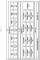
- FIG. 1 illustrates a network environment 10 including an electronic device 101 according to various embodiments of the present disclosure.
- the electronic device 100 includes a bus 110, a processor 120, a memory 130, an input/output interface 150, a display 160 and a communication interface 170.
- the bus 110 may be a circuit connecting the above described components and transmitting communication (for example, a control message) between the above described components.
- the processor 120 receives commands from other components (for example, the memory 130, the input/output interface150, the display 160, the communication interface 170) through the bus 110, analyzes the received commands, and executes calculation or data processing according to the analyzed commands.
- the memory 130 stores commands or data received from the processor 120 or other components (for example, the input/output interface 150, the display 160, or the communication interface 170) or generated by the processor 120 or other components.
- the memory 130 may include programming modules 140, for example, a kernel 141, middleware 143, an application programming interface (API) 145, and an application 147. Each of the aforementioned programming modules may be implemented by software, firmware, hardware, or a combination of two or more thereof.
- API application programming interface
- the kernel 141 controls or manages system resources (for example, the bus 110, the processor 120, or the memory 130) used for executing an operation or function implemented by the remaining other programming modules, for example, the middleware 143, the API 145, or the application 147. Further, the kernel 141 provides an interface for accessing individual components of the electronic device 101 from the middleware 143, the API 145, or the application 147 to control or manage the components.
- the middleware 143 performs a relay function of allowing the API 145 or the application 147 to communicate with the kernel 141 to exchange data.
- the middleware 143 performs a control for the operation requests (for example, scheduling or load balancing) by using a method of assigning a priority, by which system resources (for example, the bus 110, the processor 120, the memory 130 and the like) of the electronic device 100 can be used, to the application 147.
- a control for the operation requests for example, scheduling or load balancing
- system resources for example, the bus 110, the processor 120, the memory 130 and the like
- the API 145 is an interface by which the application 147 can control a function provided by the kernel 141 or the middleware 143 and includes, for example, at least one interface or function (for example, command) for a file control, a window control, image processing, or a character control.
- the input/output interface 150 can receive, for example, a command and/or data from a user, and transfer the received command and/or data to the processor 120 and/or the memory 130 through the bus 110.
- the display 160 can display an image, a video, and/or data to a user.
- the display 160 may display a graphic user interface image for interaction between the user and the electronic device 100.
- the graphic user interface image may include interface information to activate a function for correcting color of the image to be projected onto the screen.
- the interface information may be in the form of, for example, a button, a menu, or an icon.
- the communication interface170 connects communication between the electronic device 100 and the external device (for example, electronic device 102, 104 or server 106).
- the communication interface 170 may access a network 162 through wireless or wired communication to communicate with the external device 104 or the server 106, or communicate with the external device 102 via near-field communication 164 (e.g., Wi-Fi, Bluetooth or the like).
- the wireless communication includes at least one of, for example, Wi-Fi, Bluetooth (BT), near field communication (NFC), a GNSS, and cellular communication (for example, long term evolution (LTE), LTE advanced (LTE-A), code division multiple access (CDMA), wideband CDMA (WCDMA), universal mobile telephone system (UMTS), wireless broadband (WiBro) or global system for mobile (GSM)).
- the wired communication may include at least one of, for example, a universal serial bus (USB), a high definition multimedia interface (HDMI), recommended standard 232 (RS-232), and a plain old telephone service (POTS).
- USB universal serial bus
- HDMI high definition multimedia interface
- RS-232 recommended standard 232
- POTS plain old telephone service
- the server 106 supports driving of the electronic device 100 by performing at least one operation (or function) implemented by the electronic device 100.
- the server 106 may include a communication control server module that supports the communication interface 170 implemented in the electronic device 100.
- the communication control server module may include at least one of the components of the communication interface 170 to perform (on behalf of) at least one operations performed by the communication interface 170.
- FIG. 2 is a block diagram 200 of an electronic device 201 according to various embodiments of the present disclosure.
- the electronic device 201 may configure, for example, a whole or a part of the electronic device 100 illustrated in FIG. 1 .
- the electronic device 201 includes one or more application processors (APs) 210, a communication interface 220, a subscriber identification module (SIM) card 224, a memory 230, a sensor module 240, an input device 250, a display 260, an interface 270, an audio module 280, a camera module 291, a power managing module 295, a battery 296, an indicator 297, and a motor 298.
- APs application processors
- SIM subscriber identification module
- the AP 210 operates an operating system (OS) or an application program so as to control a plurality of hardware or software component elements connected to the AP 210 and execute various data processing and calculations including multimedia data.
- the AP 210 may be implemented by, for example, a system on chip (SoC).
- SoC system on chip
- the processor 210 may further include a graphic processing unit (GPU).
- the communication interface 220 (for example, communication interface 170) transmits/receives data in communication between different electronic devices (for example, the electronic device 104 and the server 106) connected to the electronic device 201 (for example, electronic device 100) through a network.
- the communication interface 220 includes a cellular module 221, a Wi-Fi module 223, a BT module 225, a GNSS module 227, a NFC module 228, and a radio frequency (RF) module 229.
- RF radio frequency
- the cellular module 221 provides a voice, a call, a video call, a short message service (SMS), or an Internet service through a communication network (for example, Long Term Evolution (LTE), LTE-A, Code Division Multiple Access (CDMA), Wideband CDMA (WCDMA), UMTS, WiBro, GSM or the like). Further, the cellular module 221 may distinguish and authenticate electronic devices within a communication network by using a subscriber identification module (for example, the SIM card 224). According to an embodiment, the cellular module 221 performs at least some of the functions which can be provided by the AP 210. For example, the cellular module 221 may perform at least some of the multimedia control functions.
- a communication network for example, Long Term Evolution (LTE), LTE-A, Code Division Multiple Access (CDMA), Wideband CDMA (WCDMA), UMTS, WiBro, GSM or the like.
- the cellular module 221 may distinguish and authenticate electronic devices within a communication network by using a subscriber identification module (
- the cellular module 221 may include a communication processor (CP). Further, the cellular module 221 may be implemented by, for example, an SoC.
- CP communication processor
- SoC SoC
- the AP 210 or the cellular module 221 may load a command or data received from at least one of a non-volatile memory and other components connected to each of the AP 210 and the cellular module 221 to a volatile memory and process the loaded command or data. Further, the AP 210 or the cellular module 221 may store data received from at least one of other components or generated by at least one of other components in a non-volatile memory.
- a communication processor CP
- the AP 210 or the cellular module 221 may store data received from at least one of other components or generated by at least one of other components in a non-volatile memory.
- Each of the Wi-Fi module 223, the BT module 225, the GNSS module 227, and the NFC module 228 may include, for example, a processor for processing data transmitted/received through the corresponding module.
- the cellular module 221, the Wi-Fi module 223, the BT module 225, the GNSS module 227, and the NFC module 228 are illustrated as blocks separate from each other in FIG. 8 , at least some (for example, two or more) of the cellular module 221, the Wi-Fi module 223, the BT module 225, the GNSS module 227, and the NFC module 228 may be included in one integrated chip (IC) or one IC package according to one embodiment.
- IC integrated chip
- At least some (for example, the CP corresponding to the cellular module 221 and the Wi-Fi processor corresponding to the Wi-Fi module 223) of the processors corresponding to the cellular module 221, the Wi-Fi module 223, the BT module 225, the GNSS module 227, and the NFC module 228 may be implemented by one SoC.
- the RF module 229 transmits/receives data, for example, an RF signal.
- the RF module 229 may include, for example, a transceiver, a power amp module (PAM), a frequency filter, a low noise amplifier (LNA) or the like.
- the RF module 229 may further include a component for transmitting/receiving electronic waves over a free air space in wireless communication, for example, a conductor, a conducting wire, or the like.
- the cellular module 221, the Wi-Fi module 223, the BT module 225, the GNSS module 227, and the NFC module 228 share one RF module 229 in FIG.
- At least one of the cellular module 221, the Wi-Fi module 223, the BT module 225, the GNSS module 227, and the NFC module 228 may transmit/receive an RF signal through a separate RF module according to one embodiment.
- the SIM card 224 is a card including a Subscriber Identification Module and may be inserted into a slot formed in a particular portion of the electronic device.
- the SIM card 224 includes unique identification information (for example, integrated circuit card identifier (ICCID)) or subscriber information (for example, international mobile subscriber identity (IMSI).
- ICCID integrated circuit card identifier
- IMSI international mobile subscriber identity
- the memory 230 may include an internal memory 232 or an external memory 234.
- the internal memory 232 may include, for example, at least one of a volatile memory (for example, a random access memory (RAM), a dynamic RAM (DRAM), a static RAM (SRAM), a synchronous dynamic RAM (SDRAM), and the like), and a non-volatile Memory (for example, a read only memory (ROM), a one-time programmable ROM (OTPROM), a programmable ROM (PROM), an erasable and programmable ROM (EPROM), an electrically erasable and programmable ROM (EEPROM), a mask ROM, a flash ROM, a NAND flash memory, an NOR flash memory, and the like).
- a volatile memory for example, a random access memory (RAM), a dynamic RAM (DRAM), a static RAM (SRAM), a synchronous dynamic RAM (SDRAM), and the like
- a non-volatile Memory for example, a read only memory (ROM
- the internal memory 232 may be a solid state drive (SSD).
- the external memory 234 may further include a flash drive, for example, a compact flash (CF), a secure digital (SD), a micro-SD, a mini-SD, an extreme Digital (xD), or a memory stick.
- the external memory 234 may be functionally connected to the electronic device 201 through various interfaces.
- the electronic device 201 may further include a storage device (or storage medium) such as a hard drive.
- the sensor module 240 measures a physical quantity or detects an operation state of the electronic device 201, and converts the measured or detected information to an electronic signal.
- the sensor module 240 may include, for example, at least one of a gesture sensor 240A, a gyro sensor 240B, an atmospheric pressure (barometric) sensor 240C, a magnetic sensor 240D, an acceleration sensor 240E, a grip sensor 240F, a proximity sensor 240G, a color sensor 240H (for example, red, green, and blue (RGB) sensor) 240H, a biometric sensor 2401, a temperature/humidity sensor 240J, an illumination (light) sensor 240K, and an ultra violet (UV) sensor 240M.
- the sensor module 240 may include, for example, a E-nose sensor, an electromyography (EMG) sensor, an electroencephalogram (EEG) sensor, an electrocardiogram (ECG) sensor, an infrared (IR) sensor, an iris sensor, a fingerprint sensor (not illustrated), and the like.
- the sensor module 240 may further include a control circuit for controlling one or more sensors included in the sensor module 240.
- the input device 250 includes a touch panel 252, a (digital) pen sensor 254, a key 256, and an ultrasonic input device 258.
- the touch panel 252 may recognize a touch input in at least one type of a capacitive type, a resistive type, an infrared type, and an acoustic wave type.
- the touch panel 252 may further include a control circuit. In the capacitive type, the touch panel 252 can recognize proximity as well as a direct touch.
- the touch panel 252 may further include a tactile layer. In this event, the touch panel 252 provides a tactile reaction to the user.
- the (digital) pen sensor 254 may be implemented, for example, using a method identical or similar to a method of receiving a touch input of the user, or using a separate recognition sheet.
- the key 256 may include, for example, a physical button, an optical key, or a key pad.
- the ultrasonic input device 258 is a device which can detect an acoustic wave by a microphone (for example, microphone 288) of the electronic device 201 through an input means generating an ultrasonic signal to identify data and can perform wireless recognition.
- the electronic device 201 receives a user input from an external device (for example, computer or server) connected to the electronic device 201 by using the communication interface 220.
- the display 260 (for example, display 160) includes a panel 262, a hologram device 264, and a projector 266.
- the panel 262 may be, for example, a liquid crystal display (LCD) or an active matrix organic light emitting diode (AM-OLED).
- the panel 262 may be implemented to be, for example, flexible, transparent, or wearable.
- the panel 262 may be configured by the touch panel 252 and one module.
- the hologram device 264 shows a stereoscopic image in the air by using interference of light.
- the projector 266 projects light on a screen to display an image.
- the screen may be located inside or outside the electronic device 201.
- the display 260 may further include a control circuit for controlling the panel 262, the hologram device 264, and the projector 266.
- the interface 270 includes, for example, a High-Definition Multimedia Interface (HDMI) 272, a Universal Serial Bus (USB) 274, an optical interface 276, and a d-subminiature (D-sub) 278.
- the interface 270 may be included in, for example, the communication interface 170 illustrated in FIG. 1 . Additionally or alternatively, the interface 270 may include, for example, a Mobile High-definition Link (MHL) interface, an SD card/multi-media card (MMC), or an infrared data association (IrDA) standard interface.
- MHL Mobile High-definition Link
- MMC Secure Digital Card
- IrDA infrared data association
- the audio module 280 bi-directionally converts a sound and an electronic signal. At least some components of the audio module 280 may be included in, for example, the input/output interface 150 illustrated in FIG. 1 .
- the audio module 280 processes sound information input or output through, for example, a speaker 282, a receiver 284, an earphone 286, the microphone 288 or the like.
- the camera module 291 is a device which can photograph a still image and a video.
- the camera module 291 may include one or more image sensors (for example, a front sensor or a back sensor), an image signal processor (ISP) (not shown) or a flash (for example, an LED or xenon lamp).
- ISP image signal processor
- flash for example, an LED or xenon lamp
- the power managing module 295 manages power of the electronic device 201.
- the power managing module 295 may include, for example, a power management integrated circuit (PMIC), a charger IC, or a battery or fuel gauge.
- PMIC power management integrated circuit
- the PMIC may be mounted to, for example, an integrated circuit or an SoC semiconductor.
- a charging method may be divided into wired and wireless methods.
- the charger IC charges a battery and prevent over voltage or over current from flowing from a charger.
- the charger IC includes a charger IC for at least one of the wired charging method and the wireless charging method.
- the wireless charging method may include, for example, a magnetic resonance method, a magnetic induction method and an electromagnetic wave method, and additional circuits for wireless charging, for example, circuits such as a coil loop, a resonant circuit, a rectifier or the like may be added.
- the battery fuel gauge measures, for example, a remaining quantity of the battery 296, or a voltage, a current, or a temperature during charging.
- the battery 296 may store or generate electricity and supply power to the electronic device 201 by using the stored or generated electricity.
- the battery 296 may include a rechargeable battery or a solar battery.
- the indicator 297 shows particular statuses of the electronic device 201 or a part (for example, AP 210) of the electronic device 201, for example, a booting status, a message status, a charging status and the like.
- the motor 298 converts an electrical signal to a mechanical vibration.
- the electronic device 201 may include a processing unit (for example, GPU) for supporting a module TV.
- the processing unit for supporting the mobile TV may process, for example, media data according to a standard of digital multimedia broadcasting (DMB), digital video broadcasting (DVB), media flow or the like.
- DMB digital multimedia broadcasting
- DVD digital video broadcasting
- Each of the components of the electronic device according to various embodiments of the present disclosure may be implemented by one or more components and the name of the corresponding component may vary depending on a type of the electronic device.
- the electronic device according to various embodiments of the present disclosure may include at least one of the above described components, a few of the components may be omitted, or additional components may be further included. Also, some of the components of the electronic device according to various embodiments of the present disclosure may be combined to form a single entity, and thus may equivalently execute functions of the corresponding components before being combined.
- FIG. 3 is a block diagram of a programming module 310 according to an embodiment of the present disclosure.
- the programming module 310 (for example, programming module 140) may be included (stored) in the electronic device 100 (for example, memory 130) illustrated in FIG. 1 .
- At least some of the programming module 310 may be formed of software, firmware, hardware, or a combination of at least two of software, firmware, and hardware.
- the programming module 310 may be executed in the hardware (for example, electronic device 201) to include an Operating System (OS) controlling resources related to the electronic device (for example, electronic device 100) or various applications (for example, applications 370) driving on the OS.
- OS Operating System
- the OS may be Android TM , iOS TM , Windows TM , Symbian TM , Tizen TM , Bada OS TM or the like.
- the programming module 310 includes a kernel 320, a middleware 330, an Application Programming Interface (API) 360, and applications 370.
- API Application Programming Interface
- the kernel 320 (for example, kernel 141) includes a system resource manager 321 and a device driver 323.
- the system resource manager 321 may include, for example, a process manager, a memory manager, and a file system manager.
- the system resource manager 321 performs a system resource control, allocation, and recall.
- the device driver 323 may include, for example, a display driver, a camera driver, a BT driver, a shared memory driver, a USB driver, a keypad driver, a Wi-Fi driver, and an audio driver. Further, according to an embodiment, the device driver 323 may include an inter-process communication (IPC) driver.
- the middleware 330 includes a plurality of modules prepared in advance to provide a function required in common by the applications 370.
- the middleware 330 provides a function through the API 360 to allow the application 370 to efficiently use limited system resources within the electronic device.
- the middleware 330 (for example, middleware 143) includes at least one of a runtime library 335, an application manager 341, a window manager 342, a multimedia manager 343, a resource manager 344, a power manager 345, a database manager 346, a package manager 347, a connection manager 348, a notification manager 349, a location manager 350, a graphic manager 351, and a security manager 352.
- the runtime library 335 includes, for example, a library module used by a complier to add a new function through a programming language while the application 370 is executed.
- the runtime library 335 executes input and output, management of a memory, a function associated with an arithmetic function and the like.
- the application manager 341 manages, for example, a life cycle of at least one of the applications 370.
- the window manager 342 manages graphical user interface (GUI) resources used on the screen.
- the multimedia manager 343 detects a format required for reproducing various media files and performs an encoding or a decoding of a media file by using a codec suitable for the corresponding format.
- the resource manager 344 manages resources such as a source code, a memory, or a storage space of at least one of the applications 370.
- the power manager 345 operates together with a basic input/output system (BIOS) to manage a battery or power and provides power information required for the operation.
- BIOS basic input/output system
- the database manager 346 manages generation, search, and change of a database to be used by at least one of the applications 370.
- the package manager 347 manages an installation or an update of an application distributed in a form of a package file.
- the connection manager 348 manages, for example, a wireless connection such as Wi-Fi or Bluetooth (BT).
- the notification manager 349 displays or notifies a user of an event such as an arrival message, an appointment, a proximity alarm or the like, in a manner that does not disturb the user.
- the location manager 350 manages location information of the electronic device.
- the graphic manager 351 manages a graphic effect provided to the user or a user interface related to the graphic effect.
- the security manager 352 provides a general security function required for a system security or a user authentication.
- the middleware 330 may further include a telephony manager for managing a voice of the electronic device or a video call function.
- the middleware 330 may generate a new middleware module through a combination of various functions of the aforementioned internal component modules and use the generated new middleware module.
- the middleware 330 may provide a module specified for each type of OS to provide a differentiated function. Further, the middleware 330 may dynamically delete some of the components of the related art or add new components. Accordingly, some of the components described in the embodiment of the present disclosure may be omitted, replaced with other components having different names but performing similar functions, or other components may be further included.
- the API 360 (for example, API 145) is a set of API programming functions, and may be provided with a different configuration according to an OS. For example, in Android TM or iOS TM , a single API set may be provided for each platform. In Tizen TM , two or more API sets may be provided.
- the applications 370 which may include an application similar to the application 147, may include, for example, a preloaded application and/or a third party application.
- the applications 370 may include a home application 371 a dialer application 372, a short messaging service (SMS)/multlimedia messaging service (MMS) application 373, an instant messaging (IM) application 374, a browser application 375, a camera application 376, an alarm application 377, a contact application 378, a voice dial application 379, an email application 380, a calendar application 381, a media player application 382, an album application 383, and a clock application 384.
- the present embodiment is not limited thereto, and the applications 370 may include any other similar and/or suitable application.
- At least a part of the programming module 310 can be implemented by commands stored in computer-readable storage media. When the commands are executed by at least one processor, e.g.
- At least one processor can perform functions corresponding to the commands.
- the computer-readable storage media may be, for example, the memory 230.
- At least a part of the programming module 310 can be implemented, e.g. executed, by, for example, the AP 210.
- At least a part of the programming module 310 may include, for example, a module, a program, a routine, a set of instructions and/or a process for performing at least one function.
- the titles of the aforementioned elements of the programming module, e.g. the programming module 310, according to the present disclosure may vary depending on the type of the OS.
- the programming module according to the present disclosure may include at least one of the aforementioned elements and/or may further include other additional elements, and/or some of the aforementioned elements may be omitted.
- the operations performed by a programming module and/or other elements according to the present disclosure may be processed through a sequential, parallel, repetitive, and/or heuristic method, and some of the operations may be omitted and/or other operations may be added.
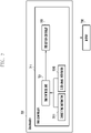
- FIG. 4 is a block diagram illustrating the configuration of an electronic device according to various embodiments of the present disclosure.
- an electronic device 400 may include a processor (e.g., processor 210 of FIG. 2 or at least one processor) 410, a memory (e.g., memory 230 of FIG. 2 ) 420, a display (e.g., display 260 of FIG. 2 ) 430, a power management module (e.g., power management module 295 of FIG. 2 ) 440, a power button (e.g., key 256 of FIG. 2 ) 450, and a battery (e.g., battery 296 of FIG. 2 ) 460.
- a processor e.g., processor 210 of FIG. 2 or at least one processor
- a memory e.g., memory 230 of FIG. 2
- a display e.g., display 260 of FIG. 2
- a power management module e.g., power management module 295 of FIG. 2
- a power button e.g., key 256 of FIG. 2
- a battery e.g., battery
- the processor 410 may perform a normal booting operation. If power-on operation is performed, the electronic device 400 may execute a boot loader, and perform kernel booting after performing a board initialization process for initializing a hardware device. Thereafter, the processor 410 may load a file system into the memory (e.g., RAM) 420, and perform normal booting to load and initialize an application.
- the memory e.g., RAM
- the memory 420 may include a volatile memory (e.g., RAM) or a nonvolatile memory (e.g., ROM or eMMC), and a boot ROM 421 may be stored in the nonvolatile memory.
- a volatile memory e.g., RAM
- a nonvolatile memory e.g., ROM or eMMC
- boot ROM 421 may be stored in the nonvolatile memory.
- the processor may perform an operation according to the function of the electronic device 400.
- the operation according to the function of the electronic device 400 may be a typical operation to perform the function of the electronic device 400, such as execution of an application of the electronic device 400, for example, based on the input of the user.
- the processor 410 may determine whether the power level is equal to or lower than a specific level (e.g., first power level).
- a specific level e.g., first power level
- the processor 410 or the power management module 440 e.g., power management module 295 of FIG. 2
- the processor 410 or the power management module 440 may have a preset power level of the battery (e.g., battery 296 of FIG. 2 ) 460, or may sense whether the power level is equal to or lower than the specific level (e.g., first power level) set by a user.
- the electronic device 400 may notify a platform (e.g., framework) of a system or an operating system (OS) of the power level of the electronic device 400 under the control of the processor 410.
- the specific level e.g., first power level
- the specific level may be a ratio of the current amount of power to the total amount of battery power (e.g., mAh).
- the specific level e.g., first power level
- the processor 410 may create a power-off command and a reboot command through the platform.
- the power-off command and the reboot command transferred from the platform are transferred to the kernel and the boot loader to end the processor 410, and the processor 410 and a sensor (e.g., sensor module 240 of FIG. 2 ) may enter into a power-off state.
- the processor 410 may display a message about the battery state on the display 430. For example, the message about the battery state that is displayed on the display 430 may be "The battery is too low. All functions are ended, and only a basic clock function can be used for a long time.”
- the processor 410 may display a message about the battery state on the display 430, and may inquire of a user whether to enter into a power-off mode.
- the specific level e.g., first power level
- the processor 410 may transfer the power-off command and the reboot command to the boot loader of the boot ROM 421. If the power-off command and the reboot command are transferred to the boot loader of the boot ROM 421, the power of the boot loader may be turned off, and a power-off flag may be set.
- the power-off flag may be an indicator for indicating that the electronic device 400 is in a power-off state.
- the processor 410 may display an animation about the power-off on the display 430 before entering into the power-off state.
- a controller 442 included in the power management module 440 may control the boot loader included in the boot ROM 421 to display time related information on the display 430 for a predetermined time.
- the power management module 440 may include a real time clock (RTC) 441 to provide the time related information, and the power management module 440 may control the RTC 441 to provide time information to the boot loader.
- RTC real time clock
- the predetermined time may be several seconds (e.g., 1-3 seconds) or less
- the time related information may be a text or an image related to the current time.
- the first input may be an input through user's pressing of the power button (or key) 450.
- the first input may correspond to user's short pressing of the power button (or key) 450.
- the power management module (e.g., power management module 295 of FIG. 2 ) may operate to supply the power to the memory 420.
- the controller 442 included in the power management module 440 may determine whether to execute booting through reading of the boot loader from the boot ROM 421. In this case, since the power-off flag is set in the boot loader, the boot loader may not perform the normal booting command of the electronic device 400, but may read the stored time information to display the time information and the time related information on the display 430.
- the power management module (e.g., power management module 295 of FIG. 2 ) may supply the power to the memory 420.
- the controller 442 included in the power management module 440 may check the power-off flag set in the boot loader. If the power-off flag is set in the boot loader, the controller 442 may not turn on the power of the processor 410, but may control the boot loader to display the time information and the time related information on the display 430.
- the processor 410 may determine whether the event occurred corresponds to a second input or a charging event. If the electronic device 400 is in a low power state, a user may replace the battery (e.g., battery 296 of FIG. 2 ) 460 of the electronic device 400, and may press the power button (or key) 450. In this case, if long pressing of the power button (or key) 450 is performed, unlike the first input, the processor 410 may recognize this as the second input to perform the normal booting command. If the power management module (e.g., power management module 295 of FIG. 2 ) transfers the second input to the processor 410, the boot loader included in the processor 410 may remove the power-off flag setting to enter into the normal booting operation.
- the power management module e.g., power management module 295 of FIG. 2
- the user may replace the battery (e.g., battery 296 of FIG. 2 ) 460 of the electronic device 400 and may reset the power-off flag.
- the power management module 440 may recognize this as the second input to make the processor 410 perform the normal booting command.
- the replaced battery (e.g., battery 296 of FIG. 2 ) 460 may include the power having a predetermined level or more.
- the user may perform charging of the electronic device 400.
- the power level of the battery (e.g., battery 296 of FIG. 2 ) 460 is equal to or higher than a specific level (e.g., second power level) after the charging operation, the processor 410 may perform the normal booting operation.
- the specific level e.g., second power level
- the specific level may be a ratio of the current amount of power to the total amount of power (e.g., mAh).
- the specific level may be 5% or more of the total amount of power of the battery (e.g., battery 296 of FIG. 2 ) 460.
- the processor 410 may display an animation about the charging event or an animation about power-on.
- the memory 430 may store an operating system (OS) or an application that is necessary for booting or operating of the electronic device 400.
- OS operating system
- the event may correspond to a first input through pressing of the power button.
- the processor 410 may transfer the power-off command and the reboot command to the boot loader and a kernel region.
- the power management module 440 may control the memory 420 to perform normal booting with respect to the processor 410.
- the processor 410 may operate to display an animation about a charging state on the display 430.
- the processor 410 may operate to display an animation about the power-on on the display 430.
- the processor 410 may operate to store time information and clock image information in the boot loader.
- the power management module 440 may control the boot loader to generate a clock image through synthesis of the time information and the clock image information.
- FIG. 5 is a flow chart illustrating a method for controlling an electronic device in a low power state according to various embodiments of the present disclosure.
- an electronic device may perform a normal booting operation. If power-on operation is performed, the electronic device 400 may execute a boot loader, and perform kernel booting after performing a board initialization process for initializing a hardware device.
- the power-on operation of the electronic device 400 may be, for example, an operation in which if a user presses a power button (or key) 450 of the electronic device 400 in a state where the electronic device 400 is in an off state, this is recognized as an input for performing turn-on (or power-on) of the electronic device 400.
- the electronic device 400 may perform an operation according to the function of the electronic device 400.
- the operation according to the function of the electronic device 400 may be, for example, a typical operation to perform the function of the electronic device 400, such as execution of an application of the electronic device 400.
- the electronic device 400 may determine whether the power level is equal to or lower than a specific level (e.g., first power level).
- the processor 410 or the power management module (e.g., power management module 295 of FIG. 2 ) of the electronic device 400 may sense whether the power level of the battery (e.g., battery 296 of FIG. 2 ) 460 is equal to or lower than the specific level (e.g., first power level) that is preset or set by the user. If the processor 410 or the power management module (e.g., power management module 295 of FIG. 2 ) of the electronic device 400 determines that the power level of the battery (e.g., battery 296 of FIG.
- the electronic device 400 may notify a platform (e.g., framework) of a system or an operating system (OS) of the power level of the electronic device 400 under the control of the processor 410.
- the specific level e.g., first power level
- the specific level may be a ratio of the current amount of power to the total amount of power (e.g., mAh) of the battery (e.g., battery 296 of FIG. 2 ) 460.
- the specific level e.g., first power level
- the specific level may be equal to or lower than 2% of the total amount of power of the battery (e.g., battery 296 of FIG. 2 ) 460.
- the electronic device 400 may move to operation 503.
- the electronic device 400 may move to operation 507.
- the electronic device 400 may create a power-off command and a reboot command through the platform.
- the power-off command and the reboot command transferred from the platform are transferred to the kernel and the boot loader to end the process, and the electronic device 400 and a sensor (e.g., sensor module 240 of FIG. 2 ) may enter into a power-off state.
- the electronic device 400 may display a message about the battery state on the display 430 to notify a user of the state information of the electronic device 400 or to request an input (or confirmation) from the user.
- the message about the battery state that is displayed on the display 430 may be "The battery is too low. All functions are ended, and only a basic clock function can be used for a long time.”
- the electronic device 400 may turn off the power of the boot loader, and may set a power-off flag.
- the power-off flag may be an indicator for indicating that the electronic device 400 is in a power-off state.
- the electronic device 400 may transfer the power-off command and the reboot command transferred from the platform to the kernel and the boot loader to end the process, and may make the processor 410 and the sensor (e.g., sensor module 240 of FIG. 2 ) enter into the power-off state.
- the processor 410 and the sensor e.g., sensor module 240 of FIG. 2
- the electronic device 400 may display an animation about the power-off before entering into the power-off state.
- the electronic device 400 may determine whether an event occurs.
- the electronic device 400 may move to operation 511.
- the electronic device 400 may move to operation 515.
- the electronic device 400 may determine whether the event occurred corresponds to a first input.
- the first input may be, for example, an input that is generated by the electronic device 400 if the user presses the power button (or key) 450.
- the power management module 440 input through the power button (or key) 450 may determine whether the event occurred corresponds to the first input.
- the power management module 440 may supply the power to the memory 420 through the controller 442, and may determine whether a power-off flag is set in the boot loader. If it is determined that the power-off flag is set in the boot loader, the power management module 440 may move to operation 517.
- the first input may be an input through user's pressing of the power button (or key) 450.
- the first input may correspond to user's short pressing of the power button (or key) 450.
- the electronic device 400 may display time related information on the display 430 for a predetermined time.
- the power management module 440 may control an RTC 441 to provide current time information to the boot loader, and the boot loader may generate the time related information through synthesis of the current time information and stored clock image information.
- the generated time related information may be displayed on the display 430 under the control of the power management module 440, for example, the controller 442.
- the RTC 441 may supply the time information to the boot loader but also the boot loader itself may store the time information therein.
- the predetermined time may be several seconds (e.g., 1-3 seconds) or less
- the time related information that is displayed on the display 430 may be a text or an image related to the current time.
- the power management module e.g., power management module 295 of FIG. 2
- the power management module 440 may supply the power to the memory 420.
- the power management module 440 may determine whether to execute booting through reading of the boot loader from a boot ROM 421. In this case, since the power-off flag is set in the boot loader at operation 509, the boot loader, at operation 517, may not perform the normal booting command of the electronic device 400, but may read the time information included in the boot loader to display the time related information on the display 430.
- the power management module (e.g., power management module 295 of FIG. 2 ) 440 of the electronic device 400 may supply the power to the memory 420.
- the power management module 440 may determine whether to execute booting through reading of the boot loader from the boot ROM 421. In this case, since the power-off flag is set in the boot loader at operation 509, the boot loader, at operation 517, may not perform the normal booting command of the electronic device 400, but may read the stored time information through accessing a parameter partition to display the time information on the display 430 under the control of a clock controller included in the boot loader.
- the electronic device 400 may display the time related information for the predetermined time at operation 517, and then may move to operation 511.
- the electronic device 400 may move to operation 519.
- the electronic device 400 may determine whether the event occurred corresponds to a second input or a charging event. If the electronic device 400 is in a low power state, a user may replace the battery (e.g., battery 296 of FIG. 2 ) 460 of the electronic device 400, and may press the power button (or key) 450. In this case, if long pressing of the power button (or key) 450 is performed, unlike the first input, the electronic device 400 may recognize this as the second input to perform the normal booting operation.
- the power management module e.g., power management module 295 of FIG. 2
- the processor 410 may perform the normal booting operation.
- the power-off flag setting in the boot loader may be removed (or reset).
- the user may perform long pressing of the power button (or key) 450 in a power-off state.
- the power management module 440 may recognize the long pressing input as the second input to enable the processor 410 to perform the normal booting command. It is disclosed that the first input corresponds to the short pressing and the second input corresponds to the long pressing, but are not limited thereto.
- the first input may be replaced by the long pressing, and the second input may be replaced by the short pressing. Further, the first input and the second input may differ from each other in the number of times of inputs.
- the first input and the second input may be related to operations of pressing the power button 450, and may differ from each other in input time and/or the number of times of inputs.
- the first input may be an input for displaying the time related information on the display 430 in the power-off state
- the second input may be an input for proceeding with the normal booting in the power-off state of the electronic device 400.
- the user may perform charging of the electronic device 400.
- the power level of the battery (e.g., battery 296 of FIG. 2 ) 460 is equal to or higher than a specific level (e.g., second power level) after the charging operation, the electronic device 400 may perform the normal booting operation.
- the specific level e.g., second power level
- the specific level may be a ratio of the current amount of power to the total amount of power (e.g., mAh).
- the specific level may be 5% or more of the total amount of power of the battery (e.g., battery 296 of FIG. 2 ) 460.
- the electronic device 400 may display an animation about the charging event or an animation about the power-on, and then moves to operation 501 to perform the normal booting operation.
- the power management module 440 may perform the normal booting command. If the normal booting is performed, the power management module 440 may supply the power to the processor 410, and the processor 410 that has received the supplied power may perform the normal booting.
- the specific level e.g., second power level
- the specific level may be a ratio of the current amount of power to the total amount of power (e.g., mAh). For example, the specific level may be 5% or more of the total amount of power of the battery (e.g., battery 296 of FIG. 2 ) 460. If the event occurred corresponds to the second input or the charging event, the electronic device 400 may display an animation about the charging event or an animation about the power-on, and then moves to operation 501 to perform the normal booting operation.
- the specific power level (e.g., second power level) at operation 519 may be higher than the specific power level (e.g., first power level) at operation 505.
- the electronic device 400 may move to operation 511.
- the controller 442 of the power management module 440 may move to operation 511.
- the electronic device 400 may move to operation 501.
- the controller 442 of the power management module 440 may move to operation 501.
- FIG. 6 is a flowchart illustrating a method for displaying time information of an electronic device in a low power state according to various embodiments of the present disclosure.
- an electronic device may perform a normal booting operation. If power-on operation is performed, the electronic device 400 may execute a boot loader, and perform kernel booting after performing a board initialization process for initializing a hardware device.
- the power-on operation of the electronic device 400 may be, for example, an operation in which if a user presses a power button (or key) 450 of the electronic device 400 in a state where the electronic device 400 is in an off state, this is recognized as an input for performing turn-on (or power-on) of the electronic device 400.
- the electronic device 400 may perform an operation according to the function of the electronic device 400.
- the operation according to the function of the electronic device 400 may be, for example, a typical operation to perform the function of the electronic device 400, such as execution of an application of the electronic device 400.
- the electronic device 400 or the power management module 440 may determine whether the power level is equal to or lower than a specific level (e.g., first power level).
- the processor 410 or the power management module (e.g., power management module 295 of FIG. 2 ) of the electronic device 400 may sense whether the power level of the battery (e.g., battery 296 of FIG. 2 ) 460 is equal to or lower than a preset specific level (e.g., first power level). If the processor 410 or the power management module (e.g., power management module 295 of FIG. 2 ) of the electronic device 400 determines that the power level of the battery (e.g., battery 296 of FIG.
- the electronic device 400 may notify a platform (e.g., framework) of a system or an operating system (OS) of the power level of the electronic device 400 under the control of the processor 410.
- the specific level e.g., first power level
- the specific level may be a ratio of the current amount of power to the total amount of power (e.g., mAh) of the battery.
- the specific level e.g., first power level
- the electronic device 400 may move to operation 603.
- the electronic device 400 may move to operation 607.
- the electronic device 400 may display a message about the state of the battery (e.g., battery 296 of FIG. 2 ) 460 on the display 430 to notify a user of the state information of the electronic device 400 or to request an input (or confirmation) from the user.
- the message about the battery state that is displayed on the display 430 may be "The battery is too low. All functions are ended, and only a basic clock function can be used for a long time.”
- the electronic device 400 may display an animation about the power-off after displaying the message about the message state on the display 430.
- the animation about the power-off may be a logo of a manufacturer and/or a product.
- the electronic device 400 may transfer the power-off command and the reboot command transferred from the platform to the kernel and the boot loader to end the process, and may make the processor 410 and the sensor (e.g., sensor module 240 of FIG. 2 ) enter into the power-off state.
- the processor 410 and the sensor e.g., sensor module 240 of FIG. 2
- the electronic device 400 may determine whether an event occurs.
- the electronic device 400 may move to operation 611.
- the electronic device 400 may move to operation 615.
- the electronic device 400 may determine whether the event occurred corresponds to a first input.
- the first input may be, for example, an input that is generated by the electronic device 400 if the user presses the power button (or key) 450.
- the power management module 440 input through the power button (or key) 450 may determine whether the event occurred corresponds to the first input.
- the power management module 440 may supply the power to the memory 420 through the controller 442, and may determine whether a power-off flag is set in the boot loader. If it is determined that the power-off flag is set in the boot loader, the power management module 440 may move to operation 617. According to an embodiment, if it is determined that the event occurred corresponds to the first input at operation 615, the electronic device 400 may move to operation 617.
- the first input may be an input through user's pressing of the power button (or key) 450.
- the first input may correspond to user's short pressing of the power button (or key) 450.
- the electronic device 400 may display time related information on the display 430 for a predetermined time.
- the power management module 440 may control an RTC 441 to provide current time information to the boot loader, and the boot loader may generate the time related information through synthesis of the current time information and stored clock image information.
- the generated time related information may be displayed on the display 430 under the control of the power management module 440, for example, the controller 442.
- the RTC 441 may supply the time information to the boot loader but also the boot loader itself may store the time information therein.
- the predetermined time may be several seconds (e.g., 1-3 seconds) or less
- the time related information that is displayed on the display 430 may be a text or an image related to the current time.
- the power management module (e.g., power management module 295 of FIG. 2 ) 440 may supply the power to the memory 420.
- the power management module 440 may determine whether to execute booting through reading of the boot loader from a boot ROM 421. In this case, since the power-off flag is set in the boot loader, the boot loader, at operation 617, may not perform the normal booting command of the electronic device 400, but may read the time information included in the boot loader to display the time related information on the display 430.
- the power management module (e.g., power management module 295 of FIG. 2 ) 440 of the electronic device 400 may supply the power to the memory 420.
- the power management module 440 may determine whether to execute booting through reading of the boot loader from the boot ROM 421. In this case, since the power-off flag is set in the boot loader, the boot loader, at operation 617, may not perform the normal booting command of the electronic device 400, but may read the stored time information through accessing a parameter partition to display the time information on the display 430 under the control of a clock controller included in the boot loader.
- the electronic device 400 may display the time related information for the predetermined time at operation 617, and then may move to operation 611.
- the electronic device 400 may move to operation 619.
- the electronic device 400 may determine whether the event occurred corresponds to a second input or a charging event. If the electronic device 400 is in a low power state, a user may replace the battery (e.g., battery 296 of FIG. 2 ) 460 of the electronic device 400, and may press the power button (or key) 450. In this case, if long pressing of the power button (or key) 450 is performed, unlike the first input, the electronic device 400 may recognize this as the second input to perform the normal booting command.
- the battery e.g., battery 296 of FIG. 2
- the electronic device 400 may recognize this as the second input to perform the normal booting command.
- the user may perform long pressing of the power button (or key) 450 in a power-off state.
- the power management module 440 may recognize the long pressing input as the second input to enable the processor 410 to perform the normal booting command.
- the user may perform charging of the electronic device 400.
- the power level of the battery (e.g., battery 296 of FIG. 2 ) 460 is equal to or higher than a specific level (e.g., second power level) after the charging operation, the electronic device 400 may perform the normal booting operation.
- the specific level e.g., second power level
- the specific level may be a ratio of the current amount of power to the total amount of power (e.g., mAh).
- the specific level may be 5% or more of the total amount of power of the battery.
- the specific power level (e.g., second power level) at operation 619 may be higher than the specific power level (e.g., first power level) at operation 505.
- the electronic device 400 may move to operation 611.
- the controller 442 of the power management module 440 may move to operation 611.
- the electronic device 400 may move to operation 621.
- the controller 442 of the power management module 440 may move to operation 621.
- the electronic device 400 may display an animation about the charging event, or may move to operation 601 to perform the normal booting command after displaying an animation about the power-on.
- the animation about the charging event may be to display the currently charging power level. If the power level of the battery (e.g., battery 296 of FIG. 2 ) 460 is equal to or higher than the specific level (e.g., second power level) during the charging operation, the electronic device 400 may perform the normal booting command.
- the specific level e.g., second power level
- the specific level may be a ratio of the current amount of power to the total amount of power (e.g., mAh).
- the specific level may be 5% or more of the total amount of power of the battery.
- the normal booting command may be performed after switching is performed from the animation about the charging event to the animation about the power-on.
- a method for displaying time information in an electronic device 400 in a low power state may include transferring a power-off command and a reboot command to the electronic device 400 if a power level of a battery (e.g., battery 296 of FIG. 2 ) is equal to or lower than a first level, setting a power-off flag in a boot loader, entering into a power-off state, and displaying on a display current time related information for a predetermined time under the control of the boot loader if an event occurs in the power-off state.
- a power level of a battery e.g., battery 296 of FIG. 2
- the method may further include displaying a message about a power state on the display 430 under the control of a processor 410 if a power level is equal to or lower than the first level.
- the method may further include displaying an animation about the power-off on the display 430 under the control of the processor 410 if the processor enters into the power-off state.
- transferring the power-off command and the reboot command may be transferring the power-off command and the reboot command to the boot loader and a kernel region.
- the method may further include performing normal booting of the electronic device 400 if it is determined that the event corresponds to a second input through pressing of the power button or a charging event.
- the processor 410 may operate to display an animation about a charging state on the display 430.
- the method may further include displaying an animation about a charging state under the control of the processor 410 if it is determined that the event corresponds to the charging event.
- the method may further include displaying an animation about a power-on under the control of the processor 410 if it is determined that the event corresponds to the second input.
- entering into the power-off state may further include storing time information and clock image information in the boot loader.
- displaying the current time related information may include generating a clock image through synthesis of the time information and the clock image information under the control of the boot loader.
- FIG. 7 is a block diagram illustrating the configuration of a boot loader according to various embodiments of the present disclosure.
- a boot loader 701 may include a clock or time controller 711.
- the time controller 711 may include a time synthesis unit 721 and a time display controller 723.
- a power-off flag may be set in the boot loader 701.
- the electronic device 400 may display time information on a display (e.g., display 430) 730 under the control of the time controller 711.
- the time controller 711 may pre-store therein current time information and clock image information, or may read them from a parameter partition.
- the time synthesis unit or device 721 of the time controller 711 may synthesize the current time information 7211 and the clock image information 7213 to transfer the synthesized information to the time display controller 723.
- the current time information and the clock image information may be information prestored before the power-off.
- the clock image information may be a clock background image to be displayed on the display 730, and may be, for example, a digital type or analog type clock image.
- the clock image may include, for example, a background image and/or an image about the hands.
- the time display controller 723 may operate to display on the display 730 time related information obtained by synthesizing the time information and the clock image.
- FIG. 8 is a diagram explaining a user interface of an electronic device in a low power state according to various embodiments of the present disclosure.
- an electronic device e.g., electronic device 400 may display a message about the state of the battery (e.g., battery 296 of FIG. 2 ) 460 on the display 430.
- the message about the battery state that is displayed on the display 430 may be "The battery is too low. All functions are ended, and only a basic clock function can be used for a long time.”
- an electronic device may display a message about the state of the battery on the display 430 to notify a user of state information of the electronic device 400 or to request an input (or confirmation) from the user.
- the message about the battery state that is displayed on the display 430 may be "Confirm/Cancel" message together with "The battery is too low. All functions are ended, and only a basic clock function can be used for a long time.” If the user presses a "Confirm” button, the electronic device may enter into a power-off mode, and otherwise, it may not enter into the power-off mode.
- the electronic device 400 may display an animation about the power-off after displaying a message about the battery state on the display 430.
- the animation about the power-off may be a logo of a manufacturer and/or a product.
- the electronic device 400 may determine whether the event occurred in the power-off state corresponds to the first input.
- the first input may be an input that is generated from the electronic device 400 through user's pressing of the power button (or key) 450.
- the first input may correspond to user's short pressing of the power button (or key) 450. If it is determined that the event occurred corresponds to the first input, the electronic device 400 may display time related information for a predetermined time.
- the time related information may be a digital type or an analog type clock image.
- the electronic device 400 may display the current time on the display (e.g., display 430) in accordance with the first input.
- the electronic device may display an animation about the charging event.
- the animation about the charging event may be display of information on currently being charged and information on the power level.
- an animation about the power-on may be displayed.
- the animation about the power-on may be a logo of a manufacturer and/or a product.
- the specific level e.g., second power level
- the normal booting command may be performed after switching is performed from the animation about the charging event to the animation about the power-on.
- FIG. 9 is a block diagram explaining a method for controlling an electronic device according to various embodiments of the present disclosure.
- an electronic device may include a boot loader 910, a platform 920, and a kernel 930. If a power management module (e.g., power management module 295 of FIG. 2 ) of the electronic device 400 determines that the power level of the battery (e.g., battery 296 of FIG. 2 ) 460 is equal to or lower than the specific level (e.g., first power level), the electronic device 400 may notify a platform thereof.
- the platform 920 may include a system notification 921 and a device driver 922. The system notification 921 of the platform 920 may transfer to the device driver 922 that the power of the battery (e.g., battery 296 of FIG.
- the device driver 922 may transfer a power-off command and a reboot command to a kernel 930 and the boot loader 910.
- the kernel 930 may operate to enter into the power-off state through transferring of the power-off command and the reboot command, and if a first input of FIGS. 4 and 5 is generated, it may operate to display time related information on the display 430 under the control of the clock controller 911. If a second input of FIGS. 4 and 5 is generated, the boot loader 910 may perform normal booting operation, and may command the kernel 930 to perform the normal booting operation.
- FIG. 10 is a block diagram explaining a method for controlling an electronic device 400 according to various embodiments of the present disclosure.
- an electronic device 400 may include a boot loader 1010, a platform 1020, and a kernel 1030. If a power management module (e.g., power management module 295 of FIG. 2 ) of the electronic device 400 determines that the power level of the battery (e.g., battery 296 of FIG. 2 ) 460 is equal to or lower than the specific level (e.g., first power level), the electronic device 400 may notify the platform 1020 thereof.
- the platform 1020 may include a system notification 1021, a device driver 1022, and a clock manager 1023.
- the clock manager 1023 may receive current time information or time image information from an outside.
- the clock image information collected by the clock manager 1023 may be a clock background image to be displayed on a display 430, for example, may be a digital type clock image or an analog type digital image.
- the clock image may include, for example, a background image and/or the hands related image.
- the clock image information collected by the clock manager 1023 may be an image that can be downloaded from the outside.
- the time manager 1023 may store the current time information and/or time image information in a clock image storage unit 1040.
- the clock image storage unit 1040 may be a parameter partition, and may be one layer of the operating system (OS) that can be accessed by the boot loader even in a power-off state.
- OS operating system
- the system notification 1021 of the platform 1020 may transfer to the device driver 1022 that the power of the battery (e.g., battery 296 of FIG. 2 ) is equal to or lower than the specific level (e.g., first power level). If the system notification 1021 transfers to the device driver 1022 that the power of the battery (e.g., battery 296 of FIG. 2 ) 460 is equal to or lower than the specific level (e.g., first power level), the device driver 1022 may transfer a power-off command and a reboot command to a kernel 1030 and the boot loader 1010. The kernel 1030 may enter into the power-off state in accordance with the power-off command of the device driver.
- the specific level e.g., first power level
- the boot loader 1010 may enter into the power-off state through transferring of the power-off command and the reboot command, and if a first input of FIGS. 4 and 5 is generated, it may operate to display time related information on the display 430 under the control of the clock controller 1021.
- the boot loader 1010 may enter into the power-off state through transferring of the power-off command and the reboot command, and if the first input of FIGS. 4 and 5 is generated, the clock controller 1021 may operate to read current time information and/or time image information from a clock image storage unit 1040, and display time related information on the display 430. If a second input of FIGS. 4 and 5 is generated, the boot loader 1010 may perform normal booting operation, and may command the kernel 1030 to perform the normal booting operation.
- FIG. 11 is a hierarchy chart explaining a method for displaying time information of an electronic device according to various embodiments of the present disclosure.
- an electronic device may include a framework 1110, a kernel 1120, and a boot loader 1130.
- the framework 1110 may be the same as the platform of FIGS. 9 and 10 .
- the framework 1110 may include a system notification 1111, a device driver 1112, and a clock manager 1113.
- the clock manager 1113 may receive time information 1114, and may store time zone/DST information 1122 in the kernel 1120.
- the DST is an abbreviation of daylight saving time, and is also called summertime.
- the time information 1114 may include at least one of booting complete information 1115, DST Start/End information 1116, network identity and time zone (NITZ) information 1117, WMS information 1118, and setting information 1119 set by a user.
- the time zone/daylight saving time (DST) information 1122 may be transferred to the boot loader 1130 to be stored in the boot loader 1130.
- the system notification 1111 may transfer to the device driver 1112 that the power of the battery (e.g., battery 296 of FIG. 2 ) is equal to or lower than the specific level (e.g., first power level). If the system notification 1111 transfers to the device driver 1112 that the power of the battery (e.g., battery 296 of FIG. 2 ) is equal to or lower than the specific level (e.g., first power level), the device driver 1112 may transfer a power-off command and a reboot command to the kernel 1120 and the boot loader 1130.
- the specific level e.g., first power level
- the kernel 1120 may enter into a power-off state 1123 in accordance with the reboot command and/or the power-off command of the device driver 1112.
- the boot loader 1130 may enter into the power-off state 1131 through transferring of the power-off command and the reboot command from the kernel 1120, and if a first input of FIGS. 4 and 5 is generated, it may perform reading 1132 of the time zone/DST information stored in the boot loader 1130 to display the read information on the display 430.
- module may include a unit that includes combinations of hardware, software, and firmware, and for example, the “module” may be interchangeably used with the term “logic, logical block, component, or circuit".
- the “module” may be the minimum unit or a part of components that are configured in a body.
- the “module” may be a minimum unit or a part thereof that performs one or more functions.
- the “module” may be mechanically or electronically implemented, and may include application-specific integrated circuit (ASIC) chip, field-programmable gate arrays (FPGAs), or programmable logical device, which perform certain operations, and which are known or to be developed.
- ASIC application-specific integrated circuit
- FPGAs field-programmable gate arrays
- At least a part of a device e.g., modules or their functions
- a method e.g., operations
- a computer-readable recording media e.g., memory 830
- the instructions are executed by a processor (e.g., processor 820)
- the processor can perform functions corresponding to the instructions.
- the computer-readable recording media may include magnetic media, such as hard disks, floppy discs, or magnetic media (e.g., magnetic tapes), optical recording media (e.g., compact disc ROM (CD-ROM), digital versatile disc (DVD)), magneto-optical media (e.g., floptical disks), and a built-in memory. Instructions may include codes that are made by compilers or codes that can be executed by interpreters.
- the modules or programming modules according to various embodiments may include at least one of the above-described constituent elements, may omit parts thereof, or may further include other additional constituent elements.
- the operations that are performed by the module, programming modules, or other constituent elements according to various embodiments may be executed in a sequential, parallel, repetitive, or heuristic method. Further, at least partial operations may be executed in a different order or may be omitted, or other operations may be added.
Landscapes
- Engineering & Computer Science (AREA)
- Theoretical Computer Science (AREA)
- General Physics & Mathematics (AREA)
- Physics & Mathematics (AREA)
- General Engineering & Computer Science (AREA)
- Human Computer Interaction (AREA)
- Signal Processing (AREA)
- Computer Networks & Wireless Communication (AREA)
- Computer Hardware Design (AREA)
- Multimedia (AREA)
- Power Engineering (AREA)
- Library & Information Science (AREA)
- Data Mining & Analysis (AREA)
- Databases & Information Systems (AREA)
- Business, Economics & Management (AREA)
- General Business, Economics & Management (AREA)
- Quality & Reliability (AREA)
- User Interface Of Digital Computer (AREA)
- Telephone Function (AREA)
Claims (13)
- Procédé d'affichage d'informations temporelles dans un appareil électronique (400) dans un état d'énergie faible, l'appareil électronique comprenant un processeur (410), une mémoire (420) comportant une mémoire morte d'amorçage (421) avec un chargeur d'amorçage, un module de gestion d'énergie (440) doté d'un organe de commande (442), une batterie (460) et un écran (430), ledit procédé comprenant :- la détermination (505, 605), par le processeur ou le module de gestion d'énergie, du fait ou non que le niveau d'énergie de la batterie est inférieur ou égal à un premier niveau et, s'il a été déterminé (505 OUI, 605 OUI) que le niveau d'énergie de la batterie est inférieur ou égal au premier niveau :- la transmission (507) d'une commande de mise hors tension auprès de l'appareil électronique ;- l'établissement (509) d'un drapeau de mise hors tension dans le chargeur d'amorçage ;- le passage (511, 611) du processeur à un état hors-tension dans lequel le processeur est mis hors tension ;- la détermination (513, 613), par le module de gestion d'énergie, du fait ou non qu'un événement spécifique correspondant à une première entrée (515, 615) réalisée par l'actionnement d'un interrupteur (450) s'est produit à l'état hors-tension du processeur ; et- à la suite de la détermination du fait que la première entrée a été réalisée (515 OUI, 615 OUI), la commande, par l'organe de commande du module de gestion d'énergie :- d'une horloge pour heure réelle (441) afin de fournir des informations en lien avec l'heure effective au chargeur d'amorçage, et- du chargeur d'amorçage pour afficher (517, 617), sur l'écran, les informations en lien avec l'heure effective pendant une durée prédéterminée compte tenu du drapeau de mise hors tension établi dans le chargeur d'amorçage, pendant que le processeur est maintenu à l'état hors-tension.
- Procédé selon la revendication 1, l'étape de détermination (505, 605) comprenant en outre :
l'affichage (607), sur l'écran, d'un message en lien avec l'état d'énergie sous la commande du processeur si le niveau d'énergie est inférieur ou égal au premier niveau. - Procédé selon la revendication 1, l'étape de détermination (505, 605) comprenant en outre :
l'affichage (609), sur l'écran, d'une animation concernant une mise hors tension sous la commande du processeur si le processeur passe à l'état hors-tension. - Procédé selon la revendication 1, dans lequel la transmission de la commande de mise hors tension comprend la transmission de la commande de mise hors tension auprès du chargeur d'amorçage et d'une région formant noyau.
- Procédé selon la revendication 1, comprenant en outre :la réalisation d'un amorçage normal (601) de l'appareil électronique s'il a été déterminé que l'événement spécifique correspond à une deuxième entrée (615 NON) réalisée par l'actionnement d'un interrupteur ou à un événement de charge (619 OUI) ;l'affichage d'une animation (621) concernant un état de charge, sur l'écran, sous la commande du processeur s'il a été déterminé que l'événement spécifique consiste en l'événement de charge ; etl'affichage d'une animation (621) concernant une mise sous tension, sur l'écran, sous la commande du processeur s'il a été déterminé que l'événement spécifique correspond à la deuxième entrée.
- Procédé selon la revendication 1,dans lequel le passage à l'état hors-tension comprend le stockage des informations temporelles et d'informations d'image d'horloge dans le chargeur d'amorçage, etdans lequel l'affichage des informations en lien avec l'heure effective comprend la production d'une image d'horloge par synthèse des informations temporelles et des informations d'image d'horloge sous la commande du chargeur d'amorçage.
- Appareil électronique (400) comprenant :une mémoire (420) comportant une mémoire morte d'amorçage (421) conçue pour y stocker un chargeur d'amorçage,un processeur (410),un module de gestion d'énergie (440) comportant un organe de commande (442) et une horloge pour heure réelle (441) conçue pour fournir des informations en lien avec l'heure effective,un interrupteur (450) conçu pour transmettre une première entrée au module de gestion d'énergie,une batterie (460), etun écran (430) ;ledit processeur ou ledit module de gestion d'énergie étant conçu pour déterminer si le niveau d'énergie de la batterie est inférieur ou égal à un premier niveau, etledit processeur, s'il a été déterminé que le niveau d'énergie de la batterie est inférieur ou égal au premier niveau, étant conçu pour :- transmettre une commande de mise hors tension auprès de l'appareil électronique,- établir un drapeau de mise hors tension dans un chargeur d'amorçage,- passer à un état hors-tension dans lequel le processeur est mis hors tension, etledit module de gestion d'énergie étant conçu pour :- déterminer si un événement spécifique correspondant à une première entrée se produit à l'état hors-tension,- à la suite de la détermination du fait que la première entrée a été réalisée, commander l'horloge pour heure réelle de façon qu'elle fournisse les informations en lien avec l'heure effective au chargeur d'amorçage, et- commander le chargeur d'amorçage afin qu'il affiche, sur l'écran, les informations en lien avec l'heure effective pendant une durée prédéterminée, pendant que le processeur est maintenu à l'état hors-tension.
- Appareil électronique selon la revendication 7, dans lequel le processeur est conçu en outre pour afficher un message concernant un état d'énergie sur l'écran si le niveau d'énergie est inférieur ou égal au premier niveau.
- Appareil électronique selon la revendication 7, dans lequel le processeur est conçu en outre pour afficher une animation concernant une mise hors tension, sur l'écran, si le processeur passe à l'état hors-tension.
- Appareil électronique selon la revendication 7, dans lequel le processeur est conçu en outre pour transmettre la commande de mise hors tension auprès du chargeur d'amorçage et d'une région formant noyau.
- Appareil électronique selon la revendication 7, dans lequel le module de gestion d'énergie est conçu en outre pour réaliser un amorçage normal du processeur sous la commande de la mémoire s'il a été déterminé que l'événement spécifique correspond à une deuxième entrée réalisée par l'actionnement d'un interrupteur ou à un événement de charge, et
dans lequel le processeur est conçu en outre pour :afficher une animation concernant un état de charge, sur l'écran, s'il a été déterminé que l'événement spécifique consiste en l'événement de charge, etafficher une animation concernant une mise sous tension, sur l'écran, s'il a été déterminé que l'événement spécifique correspond à la deuxième entrée. - Appareil électronique selon la revendication 7, dans lequel le processeur assure le stockage d'informations temporelles et d'informations d'image d'horloge dans le chargeur d'amorçage si le processeur passe à l'état hors-tension.
- Appareil électronique selon la revendication 12, dans lequel le module de gestion d'énergie est conçu en outre pour commander le chargeur d'amorçage afin qu'il produise une image d'horloge par synthèse des informations temporelles et des informations d'image d'horloge.
Applications Claiming Priority (1)
| Application Number | Priority Date | Filing Date | Title |
|---|---|---|---|
| KR1020160111142A KR102473790B1 (ko) | 2016-08-30 | 2016-08-30 | 저전력 상태에서 시간 정보 제공 방법 및 이 방법을 포함하는 전자 장치 |
Publications (2)
| Publication Number | Publication Date |
|---|---|
| EP3291051A1 EP3291051A1 (fr) | 2018-03-07 |
| EP3291051B1 true EP3291051B1 (fr) | 2022-04-06 |
Family
ID=59901325
Family Applications (1)
| Application Number | Title | Priority Date | Filing Date |
|---|---|---|---|
| EP17188355.6A Active EP3291051B1 (fr) | 2016-08-30 | 2017-08-29 | Procédé pour afficher des informations temporelles en état de faible puissance et dispositif électronique le comprenant |
Country Status (5)
| Country | Link |
|---|---|
| US (1) | US11016853B2 (fr) |
| EP (1) | EP3291051B1 (fr) |
| KR (1) | KR102473790B1 (fr) |
| CN (1) | CN107800865B (fr) |
| WO (1) | WO2018044065A1 (fr) |
Families Citing this family (7)
| Publication number | Priority date | Publication date | Assignee | Title |
|---|---|---|---|---|
| JP6327276B2 (ja) * | 2016-03-23 | 2018-05-23 | カシオ計算機株式会社 | 電子機器及び時刻表示制御方法 |
| US10848483B2 (en) * | 2016-12-08 | 2020-11-24 | Ricoh Company, Ltd. | Shared terminal, communication system, and display control method, and recording medium |
| JP6897210B2 (ja) * | 2017-03-23 | 2021-06-30 | セイコーエプソン株式会社 | 電子時計及び制御方法 |
| KR102515606B1 (ko) * | 2017-10-31 | 2023-03-28 | 삼성에스디아이 주식회사 | 배터리 충전량 표시 방법 및 이를 수행하는 배터리 팩 및 전자 기기 |
| JP2019213325A (ja) * | 2018-06-04 | 2019-12-12 | ルネサスエレクトロニクス株式会社 | コントローラ、制御方法、制御プログラム |
| KR102593265B1 (ko) | 2019-04-08 | 2023-10-25 | 삼성전자주식회사 | 디스플레이 구동 장치 및 그 동작 방법 |
| US11202190B1 (en) * | 2021-02-01 | 2021-12-14 | Tmrw Foundation Ip S. À R.L. | Backup battery, communications device and method thereof |
Citations (2)
| Publication number | Priority date | Publication date | Assignee | Title |
|---|---|---|---|---|
| US20060294407A1 (en) * | 2005-06-28 | 2006-12-28 | Intel Corporation | Response to wake event while a system is in reduced power consumption state |
| WO2016022496A2 (fr) * | 2014-08-06 | 2016-02-11 | Apple Inc. | Interfaces utilisateur de taille réduite pour la gestion d'une batterie |
Family Cites Families (41)
| Publication number | Priority date | Publication date | Assignee | Title |
|---|---|---|---|---|
| US6874094B2 (en) * | 2000-12-19 | 2005-03-29 | Microsoft Corporation | Method for locking user input elements for a small computer device by ignoring input signals if a locking signal is generated by a calendar-type application program |
| KR20030061105A (ko) * | 2002-01-10 | 2003-07-18 | 삼성전자주식회사 | 이동통신 단말기에서 배터리 저전압 시 시계를 표시할 수있는 장치 |
| US6967647B2 (en) * | 2003-01-02 | 2005-11-22 | Fujitsu Limited | Method of controlling display brightness of portable information device, and portable information device |
| KR20050001526A (ko) * | 2003-06-25 | 2005-01-07 | 엘지전자 주식회사 | 휴대폰의 시간정보 표시방법 |
| US20050151849A1 (en) * | 2004-01-13 | 2005-07-14 | Andrew Fitzhugh | Method and system for image driven clock synchronization |
| US8327448B2 (en) * | 2005-06-22 | 2012-12-04 | Intel Corporation | Protected clock management based upon a non-trusted persistent time source |
| US7765393B1 (en) * | 2006-07-11 | 2010-07-27 | Network Appliance, Inc. | Method and system of embedding a boot loader as system firmware |
| US8144120B2 (en) * | 2006-11-29 | 2012-03-27 | Belkin International | Method and system for button press and hold feedback |
| WO2008093278A1 (fr) * | 2007-02-01 | 2008-08-07 | Nxp B.V. | Commande du temps d'éveil dans un dispositif mobile |
| US8583190B1 (en) * | 2007-05-18 | 2013-11-12 | Marvell International Ltd. | Power saving technique for a wireless device |
| US8125186B2 (en) * | 2008-06-16 | 2012-02-28 | Steve Carkner | Graphic state of charge indicator for a battery charging system and method of use |
| US8971154B2 (en) * | 2009-07-14 | 2015-03-03 | Igrs Engineering Lab Ltd. | Synchronization of system time in electronic device |
| US9312728B2 (en) * | 2009-08-24 | 2016-04-12 | Access Business Group International Llc | Physical and virtual identification in a wireless power network |
| KR101596222B1 (ko) * | 2009-08-25 | 2016-02-23 | 삼성전자주식회사 | 영상 재생 장치의 부팅을 제어하는 방법 및 그 장치 |
| US8390249B2 (en) * | 2009-11-30 | 2013-03-05 | Broadcom Corporation | Battery with integrated wireless power receiver and/or RFID |
| US20110154007A1 (en) * | 2009-12-23 | 2011-06-23 | Nokia Corporation | Low energy boot options for devices |
| US8635481B1 (en) * | 2010-04-29 | 2014-01-21 | Amazon Technologies, Inc. | Power cut off mode |
| CN101937342A (zh) | 2010-09-16 | 2011-01-05 | 广东欧珀移动通信有限公司 | 一种手持移动终端时间显示方法 |
| US9027117B2 (en) * | 2010-10-04 | 2015-05-05 | Microsoft Technology Licensing, Llc | Multiple-access-level lock screen |
| US9268367B2 (en) * | 2010-10-13 | 2016-02-23 | Microsoft Technology Licensing, Llc | Use of low-power display on device |
| KR101834810B1 (ko) * | 2011-06-07 | 2018-03-06 | 엘지전자 주식회사 | 이동 단말기 및 그의 배터리 절전모드 전환 방법 |
| KR101832331B1 (ko) * | 2011-06-29 | 2018-02-26 | 엘지전자 주식회사 | 장치들 간의 무선 전력 전송 및 통신 |
| KR101799461B1 (ko) | 2011-06-30 | 2017-11-20 | 엘지전자 주식회사 | 이동 단말기 및 그의 전력 관리방법 |
| US20130040662A1 (en) * | 2011-08-14 | 2013-02-14 | Martin Elisco | Portable communication device and method for display of black screen content |
| KR102080096B1 (ko) * | 2012-10-19 | 2020-04-14 | 삼성전자주식회사 | 무선 전력 송신기, 무선 전력 수신기 및 무선 충전 네트워크에서 응급 정보 전송 방법 |
| KR20140073946A (ko) | 2012-12-07 | 2014-06-17 | 한국전자통신연구원 | 디스플레이 장치의 절전 방법 및 이를 이용한 장치 |
| KR20140109098A (ko) * | 2013-03-05 | 2014-09-15 | 주식회사 엘지화학 | 배터리의 충전량 경고장치 및 방법 |
| US20150062130A1 (en) * | 2013-08-30 | 2015-03-05 | Blackberry Limited | Low power design for autonomous animation |
| CN104602327A (zh) | 2013-10-30 | 2015-05-06 | 华为终端有限公司 | 控制供电的方法和无线终端 |
| US8972760B1 (en) * | 2013-12-20 | 2015-03-03 | Futurewei Technologies, Inc. | Method and apparatus for reducing power consumption in a mobile electronic device using a second launcher |
| KR102223277B1 (ko) * | 2014-01-06 | 2021-03-05 | 엘지전자 주식회사 | 이동 단말기 및 그것의 제어방법 |
| KR102170246B1 (ko) * | 2014-02-07 | 2020-10-26 | 삼성전자주식회사 | 영상 정보를 표시하기 위한 전자 장치 및 방법 |
| KR102175103B1 (ko) | 2014-02-21 | 2020-11-06 | 삼성전자주식회사 | 저전력 구동 방법과 이를 수행하는 전자 장치 |
| CN104798029B (zh) * | 2014-05-22 | 2019-02-12 | 华为技术有限公司 | 显示时间的方法和装置 |
| US10228751B2 (en) * | 2014-08-06 | 2019-03-12 | Apple Inc. | Low power mode |
| KR102326154B1 (ko) * | 2014-08-29 | 2021-11-15 | 삼성전자 주식회사 | 저전력 모드의 표시 방법 및 이를 지원하는 전자 장치 |
| EP2851001A3 (fr) | 2014-12-03 | 2015-04-22 | Sensirion AG | Dispositif électronique portable |
| KR102332136B1 (ko) | 2015-02-24 | 2021-11-29 | 삼성전자 주식회사 | 다수의 프로세서들을 가지는 전자장치에서 디스플레이 제어 방법 및 장치 |
| US20170075316A1 (en) * | 2015-09-11 | 2017-03-16 | Motorola Mobility Llc | Smart Watch with Power Saving Timekeeping Only Functionality and Methods Therefor |
| CN105554316B (zh) * | 2015-11-26 | 2019-04-30 | Tcl移动通信科技(宁波)有限公司 | 一种预留智能终端电池电量的实现方法及系统 |
| CN105786315A (zh) | 2016-02-26 | 2016-07-20 | 深圳天珑无线科技有限公司 | 时间显示方法及装置 |
-
2016
- 2016-08-30 KR KR1020160111142A patent/KR102473790B1/ko active IP Right Grant
-
2017
- 2017-08-28 US US15/688,232 patent/US11016853B2/en active Active
- 2017-08-29 CN CN201710759996.8A patent/CN107800865B/zh active Active
- 2017-08-29 EP EP17188355.6A patent/EP3291051B1/fr active Active
- 2017-08-30 WO PCT/KR2017/009481 patent/WO2018044065A1/fr active Application Filing
Patent Citations (2)
| Publication number | Priority date | Publication date | Assignee | Title |
|---|---|---|---|---|
| US20060294407A1 (en) * | 2005-06-28 | 2006-12-28 | Intel Corporation | Response to wake event while a system is in reduced power consumption state |
| WO2016022496A2 (fr) * | 2014-08-06 | 2016-02-11 | Apple Inc. | Interfaces utilisateur de taille réduite pour la gestion d'une batterie |
Non-Patent Citations (2)
| Title |
|---|
| JEFF BENJAMIN: "How to use Power Reserve mode on Apple Watch", 5 May 2015 (2015-05-05), XP055643021, Retrieved from the Internet <URL:https://www.idownloadblog.com/2015/05/05/how-to-use-power-reserve-mode-apple-watch/> [retrieved on 20191115] * |
| TETSUJIN: "Apple Watch - Power Reserve", 27 June 2015 (2015-06-27), pages 1 - 1, XP055643017, Retrieved from the Internet <URL:https://apple.stackexchange.com/questions/193319/power-reserve-mode-lightning-bolt> [retrieved on 20191115] * |
Also Published As
| Publication number | Publication date |
|---|---|
| US20180060175A1 (en) | 2018-03-01 |
| KR20180024626A (ko) | 2018-03-08 |
| CN107800865B (zh) | 2021-05-07 |
| EP3291051A1 (fr) | 2018-03-07 |
| KR102473790B1 (ko) | 2022-12-05 |
| US11016853B2 (en) | 2021-05-25 |
| CN107800865A (zh) | 2018-03-13 |
| WO2018044065A1 (fr) | 2018-03-08 |
Similar Documents
| Publication | Publication Date | Title |
|---|---|---|
| US11677868B2 (en) | Method and electronic device for controlling external electronic device | |
| CN107393501B (zh) | 电子设备 | |
| US10809527B2 (en) | Method for sharing contents and electronic device supporting the same | |
| EP3291051B1 (fr) | Procédé pour afficher des informations temporelles en état de faible puissance et dispositif électronique le comprenant | |
| US10338954B2 (en) | Method of switching application and electronic device therefor | |
| US10884578B2 (en) | Electronic device and method for controlling user interface of electronic device | |
| US20170068381A1 (en) | Electronic device for sensing pressure of input and method for operating the electronic device | |
| EP3389336B1 (fr) | Dispositif électronique et son procédé de fonctionnement | |
| US10042600B2 (en) | Method for controlling display and electronic device thereof | |
| CN108702806B (zh) | 电子设备及用于其的操作方法 | |
| US11217207B2 (en) | Electronic device and method for controlling display thereof | |
| US10635204B2 (en) | Device for displaying user interface based on grip sensor and stop displaying user interface absent gripping | |
| US10261744B2 (en) | Method and device for providing application using external electronic device | |
| US20170235442A1 (en) | Method and electronic device for composing screen | |
| US10863435B2 (en) | Electronic device and method for controlling communication thereof | |
| EP3520016B1 (fr) | Procédé de protection de contenus et dispositif électronique le prenant en charge | |
| KR20180004508A (ko) | 화면 표시 방법 및 이를 지원하는 전자 장치 | |
| US10936182B2 (en) | Electronic device, and method for providing screen according to location of electronic device | |
| KR102343616B1 (ko) | 전자 장치 및 그 제어 방법 | |
| US11003336B2 (en) | Method for selecting content and electronic device therefor |
Legal Events
| Date | Code | Title | Description |
|---|---|---|---|
| PUAI | Public reference made under article 153(3) epc to a published international application that has entered the european phase |
Free format text: ORIGINAL CODE: 0009012 |
|
| STAA | Information on the status of an ep patent application or granted ep patent |
Free format text: STATUS: THE APPLICATION HAS BEEN PUBLISHED |
|
| AK | Designated contracting states |
Kind code of ref document: A1 Designated state(s): AL AT BE BG CH CY CZ DE DK EE ES FI FR GB GR HR HU IE IS IT LI LT LU LV MC MK MT NL NO PL PT RO RS SE SI SK SM TR |
|
| AX | Request for extension of the european patent |
Extension state: BA ME |
|
| STAA | Information on the status of an ep patent application or granted ep patent |
Free format text: STATUS: REQUEST FOR EXAMINATION WAS MADE |
|
| 17P | Request for examination filed |
Effective date: 20180725 |
|
| RBV | Designated contracting states (corrected) |
Designated state(s): AL AT BE BG CH CY CZ DE DK EE ES FI FR GB GR HR HU IE IS IT LI LT LU LV MC MK MT NL NO PL PT RO RS SE SI SK SM TR |
|
| STAA | Information on the status of an ep patent application or granted ep patent |
Free format text: STATUS: EXAMINATION IS IN PROGRESS |
|
| 17Q | First examination report despatched |
Effective date: 20191126 |
|
| STAA | Information on the status of an ep patent application or granted ep patent |
Free format text: STATUS: EXAMINATION IS IN PROGRESS |
|
| REG | Reference to a national code |
Ref country code: DE Ref legal event code: R079 Ref document number: 602017055458 Country of ref document: DE Free format text: PREVIOUS MAIN CLASS: G06F0001320000 Ipc: G06F0001321200 |
|
| RIC1 | Information provided on ipc code assigned before grant |
Ipc: G06F 16/48 20190101ALI20210915BHEP Ipc: G04G 19/12 20060101ALI20210915BHEP Ipc: H04W 52/02 20090101ALI20210915BHEP Ipc: G06F 1/3212 20190101AFI20210915BHEP |
|
| GRAP | Despatch of communication of intention to grant a patent |
Free format text: ORIGINAL CODE: EPIDOSNIGR1 |
|
| STAA | Information on the status of an ep patent application or granted ep patent |
Free format text: STATUS: GRANT OF PATENT IS INTENDED |
|
| INTG | Intention to grant announced |
Effective date: 20211022 |
|
| GRAS | Grant fee paid |
Free format text: ORIGINAL CODE: EPIDOSNIGR3 |
|
| GRAA | (expected) grant |
Free format text: ORIGINAL CODE: 0009210 |
|
| STAA | Information on the status of an ep patent application or granted ep patent |
Free format text: STATUS: THE PATENT HAS BEEN GRANTED |
|
| AK | Designated contracting states |
Kind code of ref document: B1 Designated state(s): AL AT BE BG CH CY CZ DE DK EE ES FI FR GB GR HR HU IE IS IT LI LT LU LV MC MK MT NL NO PL PT RO RS SE SI SK SM TR |
|
| REG | Reference to a national code |
Ref country code: GB Ref legal event code: FG4D |
|
| REG | Reference to a national code |
Ref country code: CH Ref legal event code: EP |
|
| REG | Reference to a national code |
Ref country code: AT Ref legal event code: REF Ref document number: 1481975 Country of ref document: AT Kind code of ref document: T Effective date: 20220415 |
|
| REG | Reference to a national code |
Ref country code: DE Ref legal event code: R096 Ref document number: 602017055458 Country of ref document: DE |
|
| REG | Reference to a national code |
Ref country code: IE Ref legal event code: FG4D |
|
| REG | Reference to a national code |
Ref country code: LT Ref legal event code: MG9D |
|
| REG | Reference to a national code |
Ref country code: NL Ref legal event code: MP Effective date: 20220406 |
|
| REG | Reference to a national code |
Ref country code: AT Ref legal event code: MK05 Ref document number: 1481975 Country of ref document: AT Kind code of ref document: T Effective date: 20220406 |
|
| PG25 | Lapsed in a contracting state [announced via postgrant information from national office to epo] |
Ref country code: NL Free format text: LAPSE BECAUSE OF FAILURE TO SUBMIT A TRANSLATION OF THE DESCRIPTION OR TO PAY THE FEE WITHIN THE PRESCRIBED TIME-LIMIT Effective date: 20220406 |
|
| PG25 | Lapsed in a contracting state [announced via postgrant information from national office to epo] |
Ref country code: SE Free format text: LAPSE BECAUSE OF FAILURE TO SUBMIT A TRANSLATION OF THE DESCRIPTION OR TO PAY THE FEE WITHIN THE PRESCRIBED TIME-LIMIT Effective date: 20220406 Ref country code: PT Free format text: LAPSE BECAUSE OF FAILURE TO SUBMIT A TRANSLATION OF THE DESCRIPTION OR TO PAY THE FEE WITHIN THE PRESCRIBED TIME-LIMIT Effective date: 20220808 Ref country code: NO Free format text: LAPSE BECAUSE OF FAILURE TO SUBMIT A TRANSLATION OF THE DESCRIPTION OR TO PAY THE FEE WITHIN THE PRESCRIBED TIME-LIMIT Effective date: 20220706 Ref country code: LT Free format text: LAPSE BECAUSE OF FAILURE TO SUBMIT A TRANSLATION OF THE DESCRIPTION OR TO PAY THE FEE WITHIN THE PRESCRIBED TIME-LIMIT Effective date: 20220406 Ref country code: HR Free format text: LAPSE BECAUSE OF FAILURE TO SUBMIT A TRANSLATION OF THE DESCRIPTION OR TO PAY THE FEE WITHIN THE PRESCRIBED TIME-LIMIT Effective date: 20220406 Ref country code: GR Free format text: LAPSE BECAUSE OF FAILURE TO SUBMIT A TRANSLATION OF THE DESCRIPTION OR TO PAY THE FEE WITHIN THE PRESCRIBED TIME-LIMIT Effective date: 20220707 Ref country code: FI Free format text: LAPSE BECAUSE OF FAILURE TO SUBMIT A TRANSLATION OF THE DESCRIPTION OR TO PAY THE FEE WITHIN THE PRESCRIBED TIME-LIMIT Effective date: 20220406 Ref country code: ES Free format text: LAPSE BECAUSE OF FAILURE TO SUBMIT A TRANSLATION OF THE DESCRIPTION OR TO PAY THE FEE WITHIN THE PRESCRIBED TIME-LIMIT Effective date: 20220406 Ref country code: BG Free format text: LAPSE BECAUSE OF FAILURE TO SUBMIT A TRANSLATION OF THE DESCRIPTION OR TO PAY THE FEE WITHIN THE PRESCRIBED TIME-LIMIT Effective date: 20220706 Ref country code: AT Free format text: LAPSE BECAUSE OF FAILURE TO SUBMIT A TRANSLATION OF THE DESCRIPTION OR TO PAY THE FEE WITHIN THE PRESCRIBED TIME-LIMIT Effective date: 20220406 |
|
| PG25 | Lapsed in a contracting state [announced via postgrant information from national office to epo] |
Ref country code: RS Free format text: LAPSE BECAUSE OF FAILURE TO SUBMIT A TRANSLATION OF THE DESCRIPTION OR TO PAY THE FEE WITHIN THE PRESCRIBED TIME-LIMIT Effective date: 20220406 Ref country code: PL Free format text: LAPSE BECAUSE OF FAILURE TO SUBMIT A TRANSLATION OF THE DESCRIPTION OR TO PAY THE FEE WITHIN THE PRESCRIBED TIME-LIMIT Effective date: 20220406 Ref country code: LV Free format text: LAPSE BECAUSE OF FAILURE TO SUBMIT A TRANSLATION OF THE DESCRIPTION OR TO PAY THE FEE WITHIN THE PRESCRIBED TIME-LIMIT Effective date: 20220406 Ref country code: IS Free format text: LAPSE BECAUSE OF FAILURE TO SUBMIT A TRANSLATION OF THE DESCRIPTION OR TO PAY THE FEE WITHIN THE PRESCRIBED TIME-LIMIT Effective date: 20220806 |
|
| REG | Reference to a national code |
Ref country code: DE Ref legal event code: R097 Ref document number: 602017055458 Country of ref document: DE |
|
| PG25 | Lapsed in a contracting state [announced via postgrant information from national office to epo] |
Ref country code: SM Free format text: LAPSE BECAUSE OF FAILURE TO SUBMIT A TRANSLATION OF THE DESCRIPTION OR TO PAY THE FEE WITHIN THE PRESCRIBED TIME-LIMIT Effective date: 20220406 Ref country code: SK Free format text: LAPSE BECAUSE OF FAILURE TO SUBMIT A TRANSLATION OF THE DESCRIPTION OR TO PAY THE FEE WITHIN THE PRESCRIBED TIME-LIMIT Effective date: 20220406 Ref country code: RO Free format text: LAPSE BECAUSE OF FAILURE TO SUBMIT A TRANSLATION OF THE DESCRIPTION OR TO PAY THE FEE WITHIN THE PRESCRIBED TIME-LIMIT Effective date: 20220406 Ref country code: EE Free format text: LAPSE BECAUSE OF FAILURE TO SUBMIT A TRANSLATION OF THE DESCRIPTION OR TO PAY THE FEE WITHIN THE PRESCRIBED TIME-LIMIT Effective date: 20220406 Ref country code: DK Free format text: LAPSE BECAUSE OF FAILURE TO SUBMIT A TRANSLATION OF THE DESCRIPTION OR TO PAY THE FEE WITHIN THE PRESCRIBED TIME-LIMIT Effective date: 20220406 Ref country code: CZ Free format text: LAPSE BECAUSE OF FAILURE TO SUBMIT A TRANSLATION OF THE DESCRIPTION OR TO PAY THE FEE WITHIN THE PRESCRIBED TIME-LIMIT Effective date: 20220406 |
|
| PLBE | No opposition filed within time limit |
Free format text: ORIGINAL CODE: 0009261 |
|
| STAA | Information on the status of an ep patent application or granted ep patent |
Free format text: STATUS: NO OPPOSITION FILED WITHIN TIME LIMIT |
|
| 26N | No opposition filed |
Effective date: 20230110 |
|
| PG25 | Lapsed in a contracting state [announced via postgrant information from national office to epo] |
Ref country code: MC Free format text: LAPSE BECAUSE OF FAILURE TO SUBMIT A TRANSLATION OF THE DESCRIPTION OR TO PAY THE FEE WITHIN THE PRESCRIBED TIME-LIMIT Effective date: 20220406 Ref country code: AL Free format text: LAPSE BECAUSE OF FAILURE TO SUBMIT A TRANSLATION OF THE DESCRIPTION OR TO PAY THE FEE WITHIN THE PRESCRIBED TIME-LIMIT Effective date: 20220406 |
|
| REG | Reference to a national code |
Ref country code: CH Ref legal event code: PL |
|
| GBPC | Gb: european patent ceased through non-payment of renewal fee |
Effective date: 20220829 |
|
| PG25 | Lapsed in a contracting state [announced via postgrant information from national office to epo] |
Ref country code: LU Free format text: LAPSE BECAUSE OF NON-PAYMENT OF DUE FEES Effective date: 20220829 Ref country code: LI Free format text: LAPSE BECAUSE OF NON-PAYMENT OF DUE FEES Effective date: 20220831 Ref country code: CH Free format text: LAPSE BECAUSE OF NON-PAYMENT OF DUE FEES Effective date: 20220831 |
|
| REG | Reference to a national code |
Ref country code: BE Ref legal event code: MM Effective date: 20220831 |
|
| PG25 | Lapsed in a contracting state [announced via postgrant information from national office to epo] |
Ref country code: SI Free format text: LAPSE BECAUSE OF FAILURE TO SUBMIT A TRANSLATION OF THE DESCRIPTION OR TO PAY THE FEE WITHIN THE PRESCRIBED TIME-LIMIT Effective date: 20220406 |
|
| PG25 | Lapsed in a contracting state [announced via postgrant information from national office to epo] |
Ref country code: IE Free format text: LAPSE BECAUSE OF NON-PAYMENT OF DUE FEES Effective date: 20220829 Ref country code: FR Free format text: LAPSE BECAUSE OF NON-PAYMENT OF DUE FEES Effective date: 20220831 |
|
| PG25 | Lapsed in a contracting state [announced via postgrant information from national office to epo] |
Ref country code: BE Free format text: LAPSE BECAUSE OF NON-PAYMENT OF DUE FEES Effective date: 20220831 |
|
| PG25 | Lapsed in a contracting state [announced via postgrant information from national office to epo] |
Ref country code: GB Free format text: LAPSE BECAUSE OF NON-PAYMENT OF DUE FEES Effective date: 20220829 |
|
| PGFP | Annual fee paid to national office [announced via postgrant information from national office to epo] |
Ref country code: DE Payment date: 20230720 Year of fee payment: 7 |
|
| PG25 | Lapsed in a contracting state [announced via postgrant information from national office to epo] |
Ref country code: IT Free format text: LAPSE BECAUSE OF FAILURE TO SUBMIT A TRANSLATION OF THE DESCRIPTION OR TO PAY THE FEE WITHIN THE PRESCRIBED TIME-LIMIT Effective date: 20220406 |
|
| PG25 | Lapsed in a contracting state [announced via postgrant information from national office to epo] |
Ref country code: HU Free format text: LAPSE BECAUSE OF FAILURE TO SUBMIT A TRANSLATION OF THE DESCRIPTION OR TO PAY THE FEE WITHIN THE PRESCRIBED TIME-LIMIT; INVALID AB INITIO Effective date: 20170829 |
|
| PG25 | Lapsed in a contracting state [announced via postgrant information from national office to epo] |
Ref country code: CY Free format text: LAPSE BECAUSE OF FAILURE TO SUBMIT A TRANSLATION OF THE DESCRIPTION OR TO PAY THE FEE WITHIN THE PRESCRIBED TIME-LIMIT Effective date: 20220406 |