EP3290664B1 - Verfahren und vorrichtung zur herstellung eines mit metallischem natrium gefüllten motorventils - Google Patents
Verfahren und vorrichtung zur herstellung eines mit metallischem natrium gefüllten motorventils Download PDFInfo
- Publication number
- EP3290664B1 EP3290664B1 EP16786189.7A EP16786189A EP3290664B1 EP 3290664 B1 EP3290664 B1 EP 3290664B1 EP 16786189 A EP16786189 A EP 16786189A EP 3290664 B1 EP3290664 B1 EP 3290664B1
- Authority
- EP
- European Patent Office
- Prior art keywords
- metallic sodium
- hollow
- sodium
- metallic
- valve
- Prior art date
- Legal status (The legal status is an assumption and is not a legal conclusion. Google has not performed a legal analysis and makes no representation as to the accuracy of the status listed.)
- Not-in-force
Links
Images


Classifications
-
- F—MECHANICAL ENGINEERING; LIGHTING; HEATING; WEAPONS; BLASTING
- F01—MACHINES OR ENGINES IN GENERAL; ENGINE PLANTS IN GENERAL; STEAM ENGINES
- F01L—CYCLICALLY OPERATING VALVES FOR MACHINES OR ENGINES
- F01L3/00—Lift-valve, i.e. cut-off apparatus with closure members having at least a component of their opening and closing motion perpendicular to the closing faces; Parts or accessories thereof
- F01L3/12—Cooling of valves
- F01L3/14—Cooling of valves by means of a liquid or solid coolant, e.g. sodium, in a closed chamber in a valve
-
- B—PERFORMING OPERATIONS; TRANSPORTING
- B23—MACHINE TOOLS; METAL-WORKING NOT OTHERWISE PROVIDED FOR
- B23P—METAL-WORKING NOT OTHERWISE PROVIDED FOR; COMBINED OPERATIONS; UNIVERSAL MACHINE TOOLS
- B23P15/00—Making specific metal objects by operations not covered by a single other subclass or a group in this subclass
- B23P15/001—Making specific metal objects by operations not covered by a single other subclass or a group in this subclass valves or valve housings
- B23P15/002—Making specific metal objects by operations not covered by a single other subclass or a group in this subclass valves or valve housings poppet valves
-
- F—MECHANICAL ENGINEERING; LIGHTING; HEATING; WEAPONS; BLASTING
- F04—POSITIVE - DISPLACEMENT MACHINES FOR LIQUIDS; PUMPS FOR LIQUIDS OR ELASTIC FLUIDS
- F04B—POSITIVE-DISPLACEMENT MACHINES FOR LIQUIDS; PUMPS
- F04B37/00—Pumps having pertinent characteristics not provided for in, or of interest apart from, groups F04B25/00 - F04B35/00
- F04B37/02—Pumps having pertinent characteristics not provided for in, or of interest apart from, groups F04B25/00 - F04B35/00 for evacuating by absorption or adsorption
- F04B37/04—Selection of specific absorption or adsorption materials
-
- H—ELECTRICITY
- H05—ELECTRIC TECHNIQUES NOT OTHERWISE PROVIDED FOR
- H05B—ELECTRIC HEATING; ELECTRIC LIGHT SOURCES NOT OTHERWISE PROVIDED FOR; CIRCUIT ARRANGEMENTS FOR ELECTRIC LIGHT SOURCES, IN GENERAL
- H05B6/00—Heating by electric, magnetic or electromagnetic fields
- H05B6/02—Induction heating
- H05B6/10—Induction heating apparatus, other than furnaces, for specific applications
- H05B6/101—Induction heating apparatus, other than furnaces, for specific applications for local heating of metal pieces
-
- F—MECHANICAL ENGINEERING; LIGHTING; HEATING; WEAPONS; BLASTING
- F01—MACHINES OR ENGINES IN GENERAL; ENGINE PLANTS IN GENERAL; STEAM ENGINES
- F01L—CYCLICALLY OPERATING VALVES FOR MACHINES OR ENGINES
- F01L2303/00—Manufacturing of components used in valve arrangements
- F01L2303/01—Tools for producing, mounting or adjusting, e.g. some part of the distribution
Definitions
- the present invention relates to a method and a device for manufacturing engine valves filled with metallic sodium in their inside.
- a hollow part is provided and filled with metallic sodium to achieve a weight reduction and improve heat transfer efficiency of the engine valve in order for an engine to achieve a high performance, reduction of fuel consumption, or the like.
- JP2012136979A discloses a method for manufacturing a metallic-sodium-filled engine valve.
- an object of the present invention is to provide a method and a device for manufacturing metallic-sodium-filled engine valves which facilitate the temperature control while making it possible to produce continuously and efficiently.
- the invention relates to a method for manufacturing a metallic-sodium-filled engine valve according to claim 1.
- a method for manufacturing a metallic-sodium-filled engine valve according to a second aspect of the invention is the method for manufacturing a metallic-sodium-filled engine valve according to the first aspect of the invention, characterized in that the method further comprises: a getter material adding step of adding getter material into the hollow part of the hollow valve before the metallic sodium is inserted at the head part metallic sodium insertion step.
- a method for manufacturing a metallic-sodium-filled engine valve according to a third aspect of the invention is the method for manufacturing a metallic-sodium-filled engine valve according to the first or second aspect of the invention, characterized in that the head part of the hollow valve is heated by high frequency induction heating at the melting step.
- a device for manufacturing a metallic-sodium-filled engine valve is a device for manufacturing a metallic-sodium-filled engine valve in which a hollow valve having a hollow part inside a stem part and a head part as well as an opening at an upper end of the stem part is provided thereinside with metallic sodium from the opening of the stem part, and then the opening is closed to fill the metallic sodium in the engine valve, characterized in that the device comprises: a head part metallic sodium insertion unit that inserts rod-shaped metallic sodium into the hollow part of the hollow valve; a melting unit that melts the metallic sodium in the hollow part by inserting a push rod from the opening into the hollow part of the hollow valve in which the metallic sodium is inserted with the head part metallic sodium insertion unit, and by pressing the rod-shaped metallic sodium in the hollow part while heating the head part to a temperature high enough to melt the metallic sodium; a stem part cooling unit that cools the stem part of the hollow valve in a state after the
- a device for manufacturing a metallic-sodium-filled engine valve according to a fifth aspect of the invention is the device for manufacturing a metallic-sodium-filled engine valve according to the fourth aspect of the invention, characterized in that the device further comprises: a getter material adding unit that adds getter material into the hollow part of the hollow valve before the metallic sodium is inserted with the head part metallic sodium insertion unit.
- a device for manufacturing a metallic-sodium-filled engine valve according to a sixth aspect of the invention is the device for manufacturing a metallic-sodium-filled engine valve according to the fourth or fifth aspect of the invention, characterized in that the melting unit includes a heater that heats the head part of the hollow valve with the head part placed thereon so as to support the hollow valve, and a metallic sodium press that is arranged above the heater, and that moves the push rod vertically so as to insert and pull the push rod into and out of the hollow part through the opening of the hollow valve.
- a device for manufacturing a metallic-sodium-filled engine valve according to a seventh aspect of the invention is the device for manufacturing a metallic-sodium-filled engine valve according to the sixth aspect of the invention, characterized in that the heater is a high frequency induction heater.
- the rod-shaped metallic sodium is inserted into the hollow part of the hollow valve.
- the push rod is inserted through the opening into the hollow part of the hollow valve to press the rod-shaped metallic sodium in the hollow part while the head part is heated to a temperature high enough to melt metallic sodium, so that the metallic sodium in the hollow part rapidly is melted and put into the head part.
- the rod-shaped metallic sodium is inserted into the hollow part of the hollow valve so that the metallic sodium is put into the stem part.
- a hollow valve to be filled with metallic sodium has a hollow part H inside a stem part S and a head part A as well as an opening O at the upper end of the stem part S.
- Metallic-sodium-filled engine valves which are filled with metallic sodium Na in its inside can be manufactured by putting metallic sodium Na from the opening O of the stem part S of this hollow valve V into the hollow part H, and then closing the opening O.
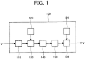
- the manufacturing device 100 described above further includes: a head part metallic sodium forming device 120 which is a head part metallic sodium forming unit for forming rod-shaped metallic sodium Na to be inserted into the hollow valve V with the head part metallic sodium insertion device 130; and a stem part metallic sodium forming device 160 which is a stem part metallic sodium forming unit for forming rod-shaped metallic sodium Na to be inserted into the hollow valve V with the stem part metallic sodium insertion device 170.
- a head part metallic sodium forming device 120 which is a head part metallic sodium forming unit for forming rod-shaped metallic sodium Na to be inserted into the hollow valve V with the head part metallic sodium insertion device 130
- a stem part metallic sodium forming device 160 which is a stem part metallic sodium forming unit for forming rod-shaped metallic sodium Na to be inserted into the hollow valve V with the stem part metallic sodium insertion device 170.
- the getter material adding device 110 includes a storage pipe 111 for storing getter material G which is titanium powder or the like, a measuring pipe 112 the upper portion of which is connected to the lower portion of the storage pipe 111 and which measures the getter material G, a first shutter 113 which is openable and closable and provided so as to partition the storage pipe 111 and the measuring pipe 112, and a second shutter 114 which is openable and closable and provided at the lower portion of the measuring pipe 112.
- the head part metallic sodium forming device 120 includes: an injection cylinder 121, into which block-shaped metallic sodium Na can be put from the proximal end side; a pressing piston 122 which can be moved to-and-fro inside the injection cylinder 121; an injection nozzle 123 which is connected to the distal end of the injection cylinder 121 and injects the block-shaped metallic sodium Na into a rod shape; a measuring pipe 124 which is arranged at the distal end side of the injection nozzle 123 to be movable and measures the rod-shaped metallic sodium Na; a cutter 125 arranged to be capable of moving forward and backward between the distal end of the injection nozzle 123 and the proximal end of the measuring pipe 124; and a shutter 126 which is openable and closable and provided at the distal end of the measuring pipe 124.
- the head part metallic sodium insertion device 130 includes: a measuring pipe moving device 131 which detachably holds the measuring pipe 124 of the head part metallic sodium forming device 120 and moves the measuring pipe 124 and the shutter 126; and an extrusion device 132 which moves an extrusion rod 132a to-and-fro such that the extrusion rod 132a is inserted into and pulled out of the measuring pipe 124.
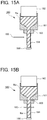
- the melting device 140 includes: a high frequency induction heater 141 which is a heater for heating the head part A of the hollow valve V by high frequency induction heating with the head part A placed thereon so as to support the hollow valve V; and a metallic sodium pressing device 142 which is a metallic sodium press which is arranged above the high frequency induction heater 141 and moves a push rod 142a vertically such that the push rod 142a is inserted into and pulled out of the hollow part H through the opening O of the hollow valve V.
- a high frequency induction heater 141 which is a heater for heating the head part A of the hollow valve V by high frequency induction heating with the head part A placed thereon so as to support the hollow valve V
- a metallic sodium pressing device 142 which is a metallic sodium press which is arranged above the high frequency induction heater 141 and moves a push rod 142a vertically such that the push rod 142a is inserted into and pulled out of the hollow part H through the opening O of the hollow valve V.
- the stem part cooling device 150 is capable of detachably gripping the stem part S of the hollow valve V to transport the hollow valve V and cooling the stem part S by coolant circulating the inside.
- the stem part metallic sodium forming device 160 includes: an injection cylinder 161, into which block-shaped metallic sodium Na can be put from the proximal end side; a pressing piston 162 which can be moved to-and-fro inside the injection cylinder 161; an injection nozzle 163 which is connected to the distal end of the injection cylinder 161 and injects the block-shaped metallic sodium Na into a rod shape; a measuring pipe 164 which is arranged at the distal end side of the injection nozzle 163 to be movable and measures the rod-shaped metallic sodium Na; a cutter 165 arranged to be capable of moving forward and backward between the distal end of the injection nozzle 163 and the proximal end of the measuring pipe 164; and a shutter 166 which is openable and closable and provided at the distal end of the measuring pipe 164.
- the head part metallic sodium insertion device 170 includes: a measuring pipe moving device 171 which detachably holds the measuring pipe 164 of the stem part metallic sodium forming device 160 and moves the measuring pipe 164 and the shutter 166; and an extrusion device 172 which moves an extrusion rod 172a to-and-fro such that the extrusion rod 172a is inserted into and pulled out of the measuring pipe 164.
- the hollow valve V is placed at a specified position in the getter material adding device 110 of the manufacturing device 100.
- the getter material G in the storage pipe 111 is supplied to the measuring pipe 112 to fill the inside of the measuring pipe 112.
- the getter material G in the measuring pipe 112 is added into the hollow part H through the opening O of the hollow valve V (up to this point, a getter material adding step).
- a specified amount of the getter material G is supplied into the hollow valve V, and the concentration of oxygen in the atmosphere (air) inside the hollow part H is reduced.
- the hollow valve V to which the getter material G has been added with the getter material adding device 110 is moved to the head part metallic sodium insertion device 130, while the measuring pipe 124 of the head part metallic sodium forming device 120 is held with the measuring pipe moving device 131 and moved to a specified position in the above head part metallic sodium insertion device 130.
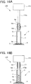
- the metallic sodium pressing device 142 is operated such that the distal end of the push rod 142a comes in contact with the upper end of the rod-shaped metallic sodium Na in the hollow part H of the hollow valve V through the opening O, as illustrated in Fig. 13B .
- the metallic sodium pressing device 142 and the high frequency induction heater 141 are operated such that the rod-shaped metallic sodium Na is pressed with the distal end of the push rod 142a while the head part A of the hollow valve V is heated to a temperature (about 98°C or more) at which metallic sodium is melted, so that the metallic sodium Na in the hollow part H of the hollow valve V is melted and put into the head part A.
- the metallic sodium pressing device 142 is operated to finish pressing the metallic sodium Na with the push rod 142a and pull the push rod 142a out of the hollow part H of the hollow valve V, while the operation of the high frequency induction heater 141 is stopped to stop heating the head part A of the hollow valve V (up to this point, a melting step).
- the stem part cooling device 150 holding the stem part S of the hollow valve V in a state after the metallic sodium Na is and put into the head part A with the melting device 140, the stem part S of the hollow valve V is cooled to below the temperature (about 98°C) at which metallic sodium N is melted while the hollow valve V is moved to a specified position in the stem part metallic sodium insertion device 170 (up to this point, a stem part cooling step).
- the measuring pipe 164 of the stem part metallic sodium forming device 160 is held with the measuring pipe moving device 171 of the stem part metallic sodium insertion device 170 and moved to a specified position in the stem part metallic sodium insertion device 170.
- the rod-shaped metallic sodium Na is inserted into the hollow part H of the hollow valve V.
- the push rod 142a is inserted through the opening O into the hollow part H of the hollow valve V to press the rod-shaped metallic sodium Na in the hollow part H while the head part A is heated to a temperature high enough to melt metallic sodium Na, so that the metallic sodium Na in the hollow part H rapidly is melted and put into the head part A.
- the stem part S is cooled to below the temperature high enough to melt metallic sodium Na
- the rod-shaped metallic sodium Na is inserted into the hollow part H of the hollow valve V, so that the metallic sodium Na is put into the stem part S.
- this embodiment facilitates the temperature control while making it possible to produce metallic-sodium-filled engine valves continuously and efficiently.
- the rod-shaped metallic sodium Na is inserted after adding the getter material G into the hollow part H of the hollow valve V in the embodiment described above, the addition of the getter material G into the hollow part H of the hollow valve V can be eliminated as another embodiment depending on the conditions such as the oxygen concentration or humidity of the surrounding atmosphere, for example.
- the manufacturing device 100 includes the metallic sodium forming devices 120 and160 for forming the rod-shaped metallic sodium Na
- the metallic sodium forming devices 120 and 160 are eliminated, and, for example, that rod-shaped metallic sodium Na formed in advance is stored in a container and it is inserted into the hollow part H of the hollow valve V with a metallic sodium insertion unit.
- the head part A of the hollow valve V is heated with the high frequency induction heater 141
- heating the head part A of the hollow valve V with the high frequency induction heater 141 makes it easy to heat the head part A quickly and raise its temperature to a target temperature in a short time, and thereby is very suitable for continuous production.
- the stem part cooling device 150 which is capable of detachably holding the stem part S of the hollow valve V to transport the hollow valve V and in which coolant circulates internally, cools the stem part S of the hollow valve V.
- the application of the stem part cooling device 150 as in the embodiment described above makes it possible to cool the stem part S of the hollow valve V rapidly, and thereby is very suitable for continuous production.
- the method and the device for manufacturing metallic-sodium-filled engine valves according to the present invention facilitates the temperature control while making it possible to produce metallic-sodium-filled engine valves continuously and efficiently, so that they can be utilized extremely advantageously from the industrial viewpoint.
Landscapes
- Engineering & Computer Science (AREA)
- Mechanical Engineering (AREA)
- General Engineering & Computer Science (AREA)
- Physics & Mathematics (AREA)
- Electromagnetism (AREA)
- Manufacture Of Electron Tubes, Discharge Lamp Vessels, Lead-In Wires, And The Like (AREA)
- Pressure Welding/Diffusion-Bonding (AREA)
Claims (7)
- Verfahren zur Herstellung eines mit Natriummetall gefüllten Motorventils, in welchem ein Hohlventil (V), das mit einem hohlen Teil (H) im Inneren eines Schaftteils (S) und einem Kopfteil (A) sowie einer Öffnung (O) an einem oberen Ende des Schaftteils (S) versehen ist, ausgehend von der Öffnung (O) des Schaftteils (S) in seinem Inneren mit Natriummetall (Na) versehen wird und die Öffnung (O) anschließend verschlossen wird, so dass das Motorventil in seinem Inneren mit dem Natriummetall (Na) gefüllt ist, wobei das Verfahren umfasst:einen Kopfteil-Natriummetalleinführschritt in Form des Einführens von stabförmigem Natriummetall (Na) in das hohle Teil (H) des Hohlventils (V);und wobei das Verfahren dadurch gekennzeichnet ist, dass es umfasst:einen Schmelzschritt in Form des Schmelzens des Natriummetalls (Na) in dem hohlen Teil (H) durch Einführen eines Stößels ausgehend von der Öffnung (O) in das hohle Teil (H) des Hohlventils (V), in welches das Natriummetall (Na) im Rahmen des Kopfteil-Natriummetalleinführschritts eingeführt worden ist, und Hineindrücken des stabförmigen Natriummetalls (Na) in das hohle Teil (H) unter gleichzeitigem Erwärmen des Kopfteils (A) auf eine Temperatur, welche hoch genug ist, um Natriummetall (Na) zu schmelzen, und anschließend Herausziehen des Stößels aus dem hohlen Teil (H) unter gleichzeitigem Beenden des Erwärmens des Kopfteils (A);einen Schaftteil-Kühlschritt in Form des Kühlens des Schaftteils (S) des Hohlventils (V) in einem Zustand, nachdem das Natriummetall (Na) geschmolzen worden ist und das Erwärmen des Kopfteils (A) des Hohlventils (V) im Rahmen des Schmelzschritts beendet worden ist, auf unterhalb des Schmelzpunkts von Natriummetall (Na); undeinen Schaftteil-Natriummetalleinführschritt in Form des Einführens von stabförmigem Natriummetall (Na) in das hohle Teil (H) des im Rahmen des Schaftteil-Kühlschritts gekühlten Hohlventils (V).
- Verfahren zur Herstellung eines mit Natriummetall gefüllten Motorventils gemäß Anspruch 1, dadurch gekennzeichnet, dass das Verfahren weiterhin umfasst:
einen Gettermaterial-Zuführschritt in Form des Zuführens von Gettermaterial (G) in das hohle Teil (H) des Hohlventils (V), bevor das Natriummetall (Na) im Rahmen des Kopfteil-Natriummetalleinführschritts eingeführt wird. - Verfahren zur Herstellung eines mit Natriummetall gefüllten Motorventils gemäß Anspruch 1 oder 2, dadurch gekennzeichnet, dass das Kopfteil (A) des Hohlventils (V) im Rahmen des Schmelzschritts durch Hochfrequenzinduktionserwärmung erwärmt wird.
- Vorrichtung zur Herstellung eines mit Natriummetall gefüllten Motorventils für die Verwendung zur Durchführung des Verfahrens zur Herstellung eines mit Natriummetall gefüllten Motorventils gemäß Anspruch 1, dadurch gekennzeichnet, dass die Vorrichtung umfasst:eine Kopfteil-Natriummetalleinführeinheit (130), welche dazu konzipiert ist, stabförmiges Natriummetall (Na) in das hohle Teil (H) des Hohlventils (V) einzuführen;eine Schmelzeinheit (140), welche dazu konzipiert ist, das Natriummetall (Na) in dem hohlen Teil (H) zu schmelzen, indem ein Stößel (142a) ausgehend von der Öffnung (O) in das hohle Teil (H) des Hohlventils (V), in welches das Natriummetall (Na) mittels der Kopfteil-Natriummetalleinführeinheit (130) eingeführt worden ist, eingeführt wird, und indem das stabförmige Natriummetall (Na) unter gleichzeitigem Erwärmen des Kopfteils (A) auf eine Temperatur, welche hoch genug ist, um das Natriummetall (Na) zu schmelzen, in das hohle Teil (H) hineingedrückt wird;eine Schaftteil-Kühleinheit (150), welche dazu konzipiert ist, das Schaftteil (S) des Hohlventils (V) in einem Zustand, nachdem das Natriummetall (Na) geschmolzen worden ist und das Erwärmen des Kopfteils (A) des Hohlventils (V) mittels der Schmelzeinheit (140) beendet worden ist, auf unterhalb des Schmelzpunkts von Natriummetall (Na) zu kühlen; undeine Schaftteil-Natriummetalleinführeinheit (170), welche dazu konzipiert ist, stabförmiges Natriummetall (Na) in das hohle Teil (H) des mittels der Schaftteil-Kühleinheit (150) gekühlten Hohlventils (V) einzuführen.
- Vorrichtung zur Herstellung eines mit Natriummetall gefüllten Motorventils gemäß Anspruch 4, dadurch gekennzeichnet, dass die Vorrichtung weiterhin umfasst:
eine Gettermaterial-Zuführeinheit (110), welche dazu konzipiert ist, dem hohlen Teil (H) des Hohlventils (V) Gettermaterial (G) zuzuführen, bevor das Natriummetall (Na) mittels der Kopfteil-Natriummetalleinführeinheit (130) eingeführt wird. - Vorrichtung zur Herstellung eines mit Natriummetall gefüllten Motorventils gemäß Anspruch 4 oder 5, dadurch gekennzeichnet, dass die Schmelzeinheit (140) umfasst:eine Heizvorrichtung (141), welche dazu konzipiert ist, das Kopfteil (A) des Hohlventils (V) zu erwärmen, wenn das Kopfteil (A) hierauf platziert ist, um auf diese Weise das Hohlventil (V) zu trägern, undeine Natriummetallpresse (142), welche oberhalb der Heizvorrichtung (141) angeordnet ist und welche dazu konzipiert ist, den Stößel (142a) in vertikaler Richtung zu bewegen, um auf diese Weise den Stößel (142a) durch die Öffnung (O) des Hohlventils (V) in das hohle Teil (H) einzuführen und aus dem hohlen Teil (H) herauszuziehen.
- Vorrichtung zur Herstellung eines mit Natriummetall gefüllten Motorventils gemäß Anspruch 6, dadurch gekennzeichnet, dass es sich bei der Heizvorrichtung (141) um eine Hochfrequenzinduktionsheizvorrichtung (141) handelt.
Priority Applications (1)
| Application Number | Priority Date | Filing Date | Title |
|---|---|---|---|
| PL16786189T PL3290664T3 (pl) | 2015-04-28 | 2016-02-26 | Sposób i urządzenie do wytwarzania zaworu silnikowego wypełnionego sodem metalicznym |
Applications Claiming Priority (2)
| Application Number | Priority Date | Filing Date | Title |
|---|---|---|---|
| JP2015091109A JP5843991B1 (ja) | 2015-04-28 | 2015-04-28 | 金属ナトリウム封入エンジンバルブの製造方法及びその装置 |
| PCT/JP2016/055748 WO2016174912A1 (ja) | 2015-04-28 | 2016-02-26 | 金属ナトリウム封入エンジンバルブの製造方法及びその装置 |
Publications (3)
| Publication Number | Publication Date |
|---|---|
| EP3290664A1 EP3290664A1 (de) | 2018-03-07 |
| EP3290664A4 EP3290664A4 (de) | 2019-01-02 |
| EP3290664B1 true EP3290664B1 (de) | 2020-04-22 |
Family
ID=55073339
Family Applications (1)
| Application Number | Title | Priority Date | Filing Date |
|---|---|---|---|
| EP16786189.7A Not-in-force EP3290664B1 (de) | 2015-04-28 | 2016-02-26 | Verfahren und vorrichtung zur herstellung eines mit metallischem natrium gefüllten motorventils |
Country Status (6)
| Country | Link |
|---|---|
| US (1) | US10677110B2 (de) |
| EP (1) | EP3290664B1 (de) |
| JP (1) | JP5843991B1 (de) |
| CN (1) | CN107532486A (de) |
| PL (1) | PL3290664T3 (de) |
| WO (1) | WO2016174912A1 (de) |
Families Citing this family (3)
| Publication number | Priority date | Publication date | Assignee | Title |
|---|---|---|---|---|
| DE102019132085A1 (de) * | 2019-11-27 | 2021-05-27 | Federal-Mogul Valvetrain Gmbh | Verfahren und Vorrichtung zum Herstellen von hohlen, innengekühlten Ventilen |
| CN115003899B (zh) * | 2020-07-14 | 2024-03-08 | 富士乌兹克斯株式会社 | 伞中空发动机气门的冷却材料填充装置以及冷却材料的填充方法 |
| DE102023200287A1 (de) * | 2023-01-16 | 2024-08-01 | Mahle International Gmbh | Ventil für eine Brennkraftmaschine und Herstellungsverfahren |
Family Cites Families (13)
| Publication number | Priority date | Publication date | Assignee | Title |
|---|---|---|---|---|
| US4459949A (en) | 1982-02-12 | 1984-07-17 | Teves-Thompson Gmbh | Liquid metal cooled internal combustion engine valves with getter |
| JP2711301B2 (ja) | 1990-03-09 | 1998-02-10 | フジオーゼックス株式会社 | 内燃機関用流体冷却弁 |
| JP2832756B2 (ja) * | 1990-12-28 | 1998-12-09 | フジオーゼックス株式会社 | 中空弁への金属ナトリウムの挿入方法及びその装置 |
| JPH07119421A (ja) * | 1993-10-25 | 1995-05-09 | Mitsubishi Heavy Ind Ltd | Na封入中空エンジンバルブの製造方法 |
| JP2002224812A (ja) * | 2001-01-29 | 2002-08-13 | Ube Machinery Corporation Ltd | 金属溶解装置及び金属溶解方法 |
| DE20308348U1 (de) * | 2003-02-18 | 2004-07-01 | Hjs Fahrzeugtechnik Gmbh & Co. | Vorrichtung zum Zuführen von Ammoniak an einen in den Abgasstrang einer Brennkraftmaschine eingeschalteten Reduktionskatalysator |
| JP2007501357A (ja) | 2003-05-26 | 2007-01-25 | ハーヨットエス ファールツォイクテクニック ゲーエムベーハー ウント コー カーゲー | 第1の相から第2の相に転移された還元剤を導く供給管から、第1の相に復帰した還元剤を除去する装置 |
| JP4688145B2 (ja) * | 2005-06-09 | 2011-05-25 | 日本碍子株式会社 | ダイキャスト装置及びダイキャスト方法 |
| JP4526097B1 (ja) * | 2009-12-24 | 2010-08-18 | 株式会社 吉村カンパニー | 中空エンジンバルブの弁傘部の製造方法及び中空エンジンバルブの弁傘部のプレス装置及び中空エンジンバルブ |
| JP5473771B2 (ja) * | 2010-05-12 | 2014-04-16 | 三菱重工業株式会社 | 金属ナトリウム封入エンジンバルブの製造方法 |
| JP2012136978A (ja) | 2010-12-24 | 2012-07-19 | Mitsubishi Heavy Ind Ltd | 金属ナトリウム供給装置 |
| JP2012136979A (ja) | 2010-12-24 | 2012-07-19 | Mitsubishi Heavy Ind Ltd | 金属ナトリウム含有エンジンバルブの製造方法、金属ナトリウム供給装置 |
| JP2014152636A (ja) | 2013-02-05 | 2014-08-25 | Mitsubishi Heavy Ind Ltd | バルブの製造方法、及びNa供給装置 |
-
2015
- 2015-04-28 JP JP2015091109A patent/JP5843991B1/ja not_active Expired - Fee Related
-
2016
- 2016-02-26 EP EP16786189.7A patent/EP3290664B1/de not_active Not-in-force
- 2016-02-26 WO PCT/JP2016/055748 patent/WO2016174912A1/ja not_active Ceased
- 2016-02-26 PL PL16786189T patent/PL3290664T3/pl unknown
- 2016-02-26 CN CN201680024164.5A patent/CN107532486A/zh active Pending
- 2016-02-26 US US15/569,606 patent/US10677110B2/en not_active Expired - Fee Related
Non-Patent Citations (1)
| Title |
|---|
| None * |
Also Published As
| Publication number | Publication date |
|---|---|
| PL3290664T3 (pl) | 2020-09-21 |
| JP5843991B1 (ja) | 2016-01-13 |
| US20180298793A1 (en) | 2018-10-18 |
| US10677110B2 (en) | 2020-06-09 |
| JP2016205331A (ja) | 2016-12-08 |
| EP3290664A1 (de) | 2018-03-07 |
| CN107532486A (zh) | 2018-01-02 |
| WO2016174912A1 (ja) | 2016-11-03 |
| EP3290664A4 (de) | 2019-01-02 |
Similar Documents
| Publication | Publication Date | Title |
|---|---|---|
| EP3290664B1 (de) | Verfahren und vorrichtung zur herstellung eines mit metallischem natrium gefüllten motorventils | |
| JP4620305B2 (ja) | 金属加圧鋳造部品を形成する装置 | |
| CN102762825A (zh) | 金属钠封入发动机气门的制造方法 | |
| KR101310779B1 (ko) | 마그네슘합금을 이용한 주조제품 제조장치 및 제조방법 | |
| KR102139349B1 (ko) | 철 금속 주물의 제조 방법 | |
| CN110508777B (zh) | 一种非晶合金立式压铸机的压铸方法 | |
| CN103302263A (zh) | 一种铜铬锆合金的非真空连续生产设备及工艺 | |
| KR20150120926A (ko) | 성형 장치, 반 응고 금속의 제조 장치, 성형 방법 및 반 응고 금속의 제조 방법 | |
| CN203957322U (zh) | 金属嵌入式加热器 | |
| KR101201780B1 (ko) | 베륨동의 연속주조장치 | |
| KR100839610B1 (ko) | 금형의 웰드 라인 발생 방지 장치 및 이를 이용한성형제품의 제조 방법 | |
| CN105567991A (zh) | 熔炼设备 | |
| CN106001823A (zh) | 激光送丝焊接方法及装置 | |
| CN103472085B (zh) | 直流电流作用下的Ti-Al基合金定向凝固实验设备及实验方法 | |
| EP3167977B1 (de) | Formvorrichtung zum formen von metall in einer umgebung mit hohem vakuum | |
| US9687907B2 (en) | Casting device with an annular duct and a casting method | |
| JP2012055928A (ja) | 部品成形装置 | |
| JP5473771B2 (ja) | 金属ナトリウム封入エンジンバルブの製造方法 | |
| WO2001003905A1 (en) | Valve gating arrangement for an insulated runner | |
| TWI337906B (en) | Metal raw material melting method for a metal molding machine | |
| KR101503593B1 (ko) | 마그네슘 주조용 저압 주조기 | |
| CN104869840A (zh) | 用于优化冷冻模制产品的取出的方法 | |
| JP2014515992A (ja) | ガラス転移点を有する材料からなる部品を金型又は成形機から取り外す方法 | |
| JP4403129B2 (ja) | 高融点金属の真空アーク溶解方法 | |
| KR101675315B1 (ko) | 용탕 분사용 노즐 보온 장치 |
Legal Events
| Date | Code | Title | Description |
|---|---|---|---|
| STAA | Information on the status of an ep patent application or granted ep patent |
Free format text: STATUS: THE INTERNATIONAL PUBLICATION HAS BEEN MADE |
|
| PUAI | Public reference made under article 153(3) epc to a published international application that has entered the european phase |
Free format text: ORIGINAL CODE: 0009012 |
|
| STAA | Information on the status of an ep patent application or granted ep patent |
Free format text: STATUS: REQUEST FOR EXAMINATION WAS MADE |
|
| 17P | Request for examination filed |
Effective date: 20171027 |
|
| AK | Designated contracting states |
Kind code of ref document: A1 Designated state(s): AL AT BE BG CH CY CZ DE DK EE ES FI FR GB GR HR HU IE IS IT LI LT LU LV MC MK MT NL NO PL PT RO RS SE SI SK SM TR |
|
| AX | Request for extension of the european patent |
Extension state: BA ME |
|
| DAV | Request for validation of the european patent (deleted) | ||
| DAX | Request for extension of the european patent (deleted) | ||
| A4 | Supplementary search report drawn up and despatched |
Effective date: 20181205 |
|
| RIC1 | Information provided on ipc code assigned before grant |
Ipc: H05B 6/10 20060101ALI20181128BHEP Ipc: B23P 15/00 20060101ALI20181128BHEP Ipc: F01L 3/14 20060101AFI20181128BHEP Ipc: F01L 3/24 20060101ALI20181128BHEP Ipc: F04B 37/04 20060101ALI20181128BHEP |
|
| GRAP | Despatch of communication of intention to grant a patent |
Free format text: ORIGINAL CODE: EPIDOSNIGR1 |
|
| STAA | Information on the status of an ep patent application or granted ep patent |
Free format text: STATUS: GRANT OF PATENT IS INTENDED |
|
| INTG | Intention to grant announced |
Effective date: 20191106 |
|
| GRAS | Grant fee paid |
Free format text: ORIGINAL CODE: EPIDOSNIGR3 |
|
| GRAA | (expected) grant |
Free format text: ORIGINAL CODE: 0009210 |
|
| STAA | Information on the status of an ep patent application or granted ep patent |
Free format text: STATUS: THE PATENT HAS BEEN GRANTED |
|
| AK | Designated contracting states |
Kind code of ref document: B1 Designated state(s): AL AT BE BG CH CY CZ DE DK EE ES FI FR GB GR HR HU IE IS IT LI LT LU LV MC MK MT NL NO PL PT RO RS SE SI SK SM TR |
|
| REG | Reference to a national code |
Ref country code: CH Ref legal event code: EP |
|
| REG | Reference to a national code |
Ref country code: IE Ref legal event code: FG4D |
|
| REG | Reference to a national code |
Ref country code: DE Ref legal event code: R096 Ref document number: 602016034661 Country of ref document: DE |
|
| REG | Reference to a national code |
Ref country code: AT Ref legal event code: REF Ref document number: 1260355 Country of ref document: AT Kind code of ref document: T Effective date: 20200515 |
|
| REG | Reference to a national code |
Ref country code: LT Ref legal event code: MG4D |
|
| REG | Reference to a national code |
Ref country code: NL Ref legal event code: MP Effective date: 20200422 |
|
| PG25 | Lapsed in a contracting state [announced via postgrant information from national office to epo] |
Ref country code: IS Free format text: LAPSE BECAUSE OF FAILURE TO SUBMIT A TRANSLATION OF THE DESCRIPTION OR TO PAY THE FEE WITHIN THE PRESCRIBED TIME-LIMIT Effective date: 20200822 Ref country code: NO Free format text: LAPSE BECAUSE OF FAILURE TO SUBMIT A TRANSLATION OF THE DESCRIPTION OR TO PAY THE FEE WITHIN THE PRESCRIBED TIME-LIMIT Effective date: 20200722 Ref country code: FI Free format text: LAPSE BECAUSE OF FAILURE TO SUBMIT A TRANSLATION OF THE DESCRIPTION OR TO PAY THE FEE WITHIN THE PRESCRIBED TIME-LIMIT Effective date: 20200422 Ref country code: GR Free format text: LAPSE BECAUSE OF FAILURE TO SUBMIT A TRANSLATION OF THE DESCRIPTION OR TO PAY THE FEE WITHIN THE PRESCRIBED TIME-LIMIT Effective date: 20200723 Ref country code: PT Free format text: LAPSE BECAUSE OF FAILURE TO SUBMIT A TRANSLATION OF THE DESCRIPTION OR TO PAY THE FEE WITHIN THE PRESCRIBED TIME-LIMIT Effective date: 20200824 Ref country code: LT Free format text: LAPSE BECAUSE OF FAILURE TO SUBMIT A TRANSLATION OF THE DESCRIPTION OR TO PAY THE FEE WITHIN THE PRESCRIBED TIME-LIMIT Effective date: 20200422 Ref country code: NL Free format text: LAPSE BECAUSE OF FAILURE TO SUBMIT A TRANSLATION OF THE DESCRIPTION OR TO PAY THE FEE WITHIN THE PRESCRIBED TIME-LIMIT Effective date: 20200422 Ref country code: SE Free format text: LAPSE BECAUSE OF FAILURE TO SUBMIT A TRANSLATION OF THE DESCRIPTION OR TO PAY THE FEE WITHIN THE PRESCRIBED TIME-LIMIT Effective date: 20200422 |
|
| REG | Reference to a national code |
Ref country code: AT Ref legal event code: MK05 Ref document number: 1260355 Country of ref document: AT Kind code of ref document: T Effective date: 20200422 |
|
| PG25 | Lapsed in a contracting state [announced via postgrant information from national office to epo] |
Ref country code: LV Free format text: LAPSE BECAUSE OF FAILURE TO SUBMIT A TRANSLATION OF THE DESCRIPTION OR TO PAY THE FEE WITHIN THE PRESCRIBED TIME-LIMIT Effective date: 20200422 Ref country code: HR Free format text: LAPSE BECAUSE OF FAILURE TO SUBMIT A TRANSLATION OF THE DESCRIPTION OR TO PAY THE FEE WITHIN THE PRESCRIBED TIME-LIMIT Effective date: 20200422 Ref country code: RS Free format text: LAPSE BECAUSE OF FAILURE TO SUBMIT A TRANSLATION OF THE DESCRIPTION OR TO PAY THE FEE WITHIN THE PRESCRIBED TIME-LIMIT Effective date: 20200422 Ref country code: BG Free format text: LAPSE BECAUSE OF FAILURE TO SUBMIT A TRANSLATION OF THE DESCRIPTION OR TO PAY THE FEE WITHIN THE PRESCRIBED TIME-LIMIT Effective date: 20200722 |
|
| PG25 | Lapsed in a contracting state [announced via postgrant information from national office to epo] |
Ref country code: AL Free format text: LAPSE BECAUSE OF FAILURE TO SUBMIT A TRANSLATION OF THE DESCRIPTION OR TO PAY THE FEE WITHIN THE PRESCRIBED TIME-LIMIT Effective date: 20200422 |
|
| REG | Reference to a national code |
Ref country code: DE Ref legal event code: R097 Ref document number: 602016034661 Country of ref document: DE |
|
| PG25 | Lapsed in a contracting state [announced via postgrant information from national office to epo] |
Ref country code: SM Free format text: LAPSE BECAUSE OF FAILURE TO SUBMIT A TRANSLATION OF THE DESCRIPTION OR TO PAY THE FEE WITHIN THE PRESCRIBED TIME-LIMIT Effective date: 20200422 Ref country code: AT Free format text: LAPSE BECAUSE OF FAILURE TO SUBMIT A TRANSLATION OF THE DESCRIPTION OR TO PAY THE FEE WITHIN THE PRESCRIBED TIME-LIMIT Effective date: 20200422 Ref country code: EE Free format text: LAPSE BECAUSE OF FAILURE TO SUBMIT A TRANSLATION OF THE DESCRIPTION OR TO PAY THE FEE WITHIN THE PRESCRIBED TIME-LIMIT Effective date: 20200422 Ref country code: DK Free format text: LAPSE BECAUSE OF FAILURE TO SUBMIT A TRANSLATION OF THE DESCRIPTION OR TO PAY THE FEE WITHIN THE PRESCRIBED TIME-LIMIT Effective date: 20200422 Ref country code: ES Free format text: LAPSE BECAUSE OF FAILURE TO SUBMIT A TRANSLATION OF THE DESCRIPTION OR TO PAY THE FEE WITHIN THE PRESCRIBED TIME-LIMIT Effective date: 20200422 Ref country code: RO Free format text: LAPSE BECAUSE OF FAILURE TO SUBMIT A TRANSLATION OF THE DESCRIPTION OR TO PAY THE FEE WITHIN THE PRESCRIBED TIME-LIMIT Effective date: 20200422 Ref country code: IT Free format text: LAPSE BECAUSE OF FAILURE TO SUBMIT A TRANSLATION OF THE DESCRIPTION OR TO PAY THE FEE WITHIN THE PRESCRIBED TIME-LIMIT Effective date: 20200422 |
|
| PG25 | Lapsed in a contracting state [announced via postgrant information from national office to epo] |
Ref country code: SK Free format text: LAPSE BECAUSE OF FAILURE TO SUBMIT A TRANSLATION OF THE DESCRIPTION OR TO PAY THE FEE WITHIN THE PRESCRIBED TIME-LIMIT Effective date: 20200422 |
|
| PLBE | No opposition filed within time limit |
Free format text: ORIGINAL CODE: 0009261 |
|
| STAA | Information on the status of an ep patent application or granted ep patent |
Free format text: STATUS: NO OPPOSITION FILED WITHIN TIME LIMIT |
|
| 26N | No opposition filed |
Effective date: 20210125 |
|
| PG25 | Lapsed in a contracting state [announced via postgrant information from national office to epo] |
Ref country code: SI Free format text: LAPSE BECAUSE OF FAILURE TO SUBMIT A TRANSLATION OF THE DESCRIPTION OR TO PAY THE FEE WITHIN THE PRESCRIBED TIME-LIMIT Effective date: 20200422 |
|
| PG25 | Lapsed in a contracting state [announced via postgrant information from national office to epo] |
Ref country code: MC Free format text: LAPSE BECAUSE OF FAILURE TO SUBMIT A TRANSLATION OF THE DESCRIPTION OR TO PAY THE FEE WITHIN THE PRESCRIBED TIME-LIMIT Effective date: 20200422 |
|
| GBPC | Gb: european patent ceased through non-payment of renewal fee |
Effective date: 20210226 |
|
| REG | Reference to a national code |
Ref country code: BE Ref legal event code: MM Effective date: 20210228 |
|
| PG25 | Lapsed in a contracting state [announced via postgrant information from national office to epo] |
Ref country code: LU Free format text: LAPSE BECAUSE OF NON-PAYMENT OF DUE FEES Effective date: 20210226 Ref country code: LI Free format text: LAPSE BECAUSE OF NON-PAYMENT OF DUE FEES Effective date: 20210228 Ref country code: CH Free format text: LAPSE BECAUSE OF NON-PAYMENT OF DUE FEES Effective date: 20210228 |
|
| PG25 | Lapsed in a contracting state [announced via postgrant information from national office to epo] |
Ref country code: IE Free format text: LAPSE BECAUSE OF NON-PAYMENT OF DUE FEES Effective date: 20210226 Ref country code: GB Free format text: LAPSE BECAUSE OF NON-PAYMENT OF DUE FEES Effective date: 20210226 |
|
| PGFP | Annual fee paid to national office [announced via postgrant information from national office to epo] |
Ref country code: DE Payment date: 20220208 Year of fee payment: 7 |
|
| PGFP | Annual fee paid to national office [announced via postgrant information from national office to epo] |
Ref country code: PL Payment date: 20220216 Year of fee payment: 7 Ref country code: FR Payment date: 20220221 Year of fee payment: 7 Ref country code: CZ Payment date: 20220216 Year of fee payment: 7 |
|
| PG25 | Lapsed in a contracting state [announced via postgrant information from national office to epo] |
Ref country code: BE Free format text: LAPSE BECAUSE OF NON-PAYMENT OF DUE FEES Effective date: 20210228 |
|
| REG | Reference to a national code |
Ref country code: DE Ref legal event code: R081 Ref document number: 602016034661 Country of ref document: DE Owner name: FUJI OOZX INC., KIKUGAWA-SHI, JP Free format text: FORMER OWNER: FUJI HOLLOW VALVE INC., KIKUGAWA-SHI, SHIZUOKA, JP |
|
| PG25 | Lapsed in a contracting state [announced via postgrant information from national office to epo] |
Ref country code: CY Free format text: LAPSE BECAUSE OF FAILURE TO SUBMIT A TRANSLATION OF THE DESCRIPTION OR TO PAY THE FEE WITHIN THE PRESCRIBED TIME-LIMIT Effective date: 20200422 |
|
| PG25 | Lapsed in a contracting state [announced via postgrant information from national office to epo] |
Ref country code: HU Free format text: LAPSE BECAUSE OF FAILURE TO SUBMIT A TRANSLATION OF THE DESCRIPTION OR TO PAY THE FEE WITHIN THE PRESCRIBED TIME-LIMIT; INVALID AB INITIO Effective date: 20160226 |
|
| REG | Reference to a national code |
Ref country code: DE Ref legal event code: R119 Ref document number: 602016034661 Country of ref document: DE |
|
| PG25 | Lapsed in a contracting state [announced via postgrant information from national office to epo] |
Ref country code: CZ Free format text: LAPSE BECAUSE OF NON-PAYMENT OF DUE FEES Effective date: 20230226 |
|
| PG25 | Lapsed in a contracting state [announced via postgrant information from national office to epo] |
Ref country code: FR Free format text: LAPSE BECAUSE OF NON-PAYMENT OF DUE FEES Effective date: 20230228 Ref country code: DE Free format text: LAPSE BECAUSE OF NON-PAYMENT OF DUE FEES Effective date: 20230901 |
|
| PG25 | Lapsed in a contracting state [announced via postgrant information from national office to epo] |
Ref country code: MK Free format text: LAPSE BECAUSE OF FAILURE TO SUBMIT A TRANSLATION OF THE DESCRIPTION OR TO PAY THE FEE WITHIN THE PRESCRIBED TIME-LIMIT Effective date: 20200422 |
|
| PG25 | Lapsed in a contracting state [announced via postgrant information from national office to epo] |
Ref country code: TR Free format text: LAPSE BECAUSE OF FAILURE TO SUBMIT A TRANSLATION OF THE DESCRIPTION OR TO PAY THE FEE WITHIN THE PRESCRIBED TIME-LIMIT Effective date: 20200422 |
|
| PG25 | Lapsed in a contracting state [announced via postgrant information from national office to epo] |
Ref country code: MT Free format text: LAPSE BECAUSE OF FAILURE TO SUBMIT A TRANSLATION OF THE DESCRIPTION OR TO PAY THE FEE WITHIN THE PRESCRIBED TIME-LIMIT Effective date: 20200422 |
|
| PG25 | Lapsed in a contracting state [announced via postgrant information from national office to epo] |
Ref country code: PL Free format text: LAPSE BECAUSE OF NON-PAYMENT OF DUE FEES Effective date: 20230226 |