EP3290550B1 - Maintenance device for the maintenance of the work stations of a textile machine and textile machine - Google Patents
Maintenance device for the maintenance of the work stations of a textile machine and textile machine Download PDFInfo
- Publication number
- EP3290550B1 EP3290550B1 EP17187783.0A EP17187783A EP3290550B1 EP 3290550 B1 EP3290550 B1 EP 3290550B1 EP 17187783 A EP17187783 A EP 17187783A EP 3290550 B1 EP3290550 B1 EP 3290550B1
- Authority
- EP
- European Patent Office
- Prior art keywords
- maintenance device
- maintenance
- operating
- operating unit
- textile machine
- Prior art date
- Legal status (The legal status is an assumption and is not a legal conclusion. Google has not performed a legal analysis and makes no representation as to the accuracy of the status listed.)
- Active
Links
Images


Classifications
-
- D—TEXTILES; PAPER
- D01—NATURAL OR MAN-MADE THREADS OR FIBRES; SPINNING
- D01H—SPINNING OR TWISTING
- D01H13/00—Other common constructional features, details or accessories
- D01H13/005—Service carriages travelling along the machines
-
- D—TEXTILES; PAPER
- D01—NATURAL OR MAN-MADE THREADS OR FIBRES; SPINNING
- D01H—SPINNING OR TWISTING
- D01H15/00—Piecing arrangements ; Automatic end-finding, e.g. by suction and reverse package rotation; Devices for temporarily storing yarn during piecing
- D01H15/013—Carriages travelling along the machines
-
- B—PERFORMING OPERATIONS; TRANSPORTING
- B65—CONVEYING; PACKING; STORING; HANDLING THIN OR FILAMENTARY MATERIAL
- B65H—HANDLING THIN OR FILAMENTARY MATERIAL, e.g. SHEETS, WEBS, CABLES
- B65H54/00—Winding, coiling, or depositing filamentary material
- B65H54/02—Winding and traversing material on to reels, bobbins, tubes, or like package cores or formers
- B65H54/22—Automatic winding machines, i.e. machines with servicing units for automatically performing end-finding, interconnecting of successive lengths of material, controlling and fault-detecting of the running material and replacing or removing of full or empty cores
- B65H54/26—Automatic winding machines, i.e. machines with servicing units for automatically performing end-finding, interconnecting of successive lengths of material, controlling and fault-detecting of the running material and replacing or removing of full or empty cores having one or more servicing units moving along a plurality of fixed winding units
-
- B—PERFORMING OPERATIONS; TRANSPORTING
- B65—CONVEYING; PACKING; STORING; HANDLING THIN OR FILAMENTARY MATERIAL
- B65H—HANDLING THIN OR FILAMENTARY MATERIAL, e.g. SHEETS, WEBS, CABLES
- B65H67/00—Replacing or removing cores, receptacles, or completed packages at paying-out, winding, or depositing stations
- B65H67/06—Supplying cores, receptacles, or packages to, or transporting from, winding or depositing stations
-
- D—TEXTILES; PAPER
- D01—NATURAL OR MAN-MADE THREADS OR FIBRES; SPINNING
- D01H—SPINNING OR TWISTING
- D01H4/00—Open-end spinning machines or arrangements for imparting twist to independently moving fibres separated from slivers; Piecing arrangements therefor; Covering endless core threads with fibres by open-end spinning techniques
- D01H4/48—Piecing arrangements; Control therefor
-
- D—TEXTILES; PAPER
- D01—NATURAL OR MAN-MADE THREADS OR FIBRES; SPINNING
- D01H—SPINNING OR TWISTING
- D01H15/00—Piecing arrangements ; Automatic end-finding, e.g. by suction and reverse package rotation; Devices for temporarily storing yarn during piecing
- D01H15/002—Piecing arrangements ; Automatic end-finding, e.g. by suction and reverse package rotation; Devices for temporarily storing yarn during piecing for false-twisting spinning machines
Definitions
- the present invention relates to a maintenance device for maintaining adjacent work stations of a textile machine, in particular a spinning machine, with an operating unit which has at least one operating component for maintaining the work stations, and with a guide unit by means of which the maintenance device can be moved on a running rail along the work stations and which defines a direction of travel of the maintenance facility.
- the maintenance device can be moved from a maintenance position in which one of the work stations can be serviced by the maintenance device into an inspection position in which the maintenance device can be inspected.
- the invention also relates to a corresponding textile machine with a maintenance device.
- a maintenance device for maintaining workplaces which can be moved on a running rail.
- the maintenance device for inspection together with a part of the running rail, is pivoted relative to the work stations, so that the maintenance device is in an inspection position and can be inspected.
- a further maintenance facility can thereby enter the work path of the maintenance facility to be inspected and temporarily take over the maintenance of the workplaces located there.
- the disadvantage of this prior art is that the pivotable running rail is constructed in a complex manner.
- the object of the present invention is therefore to eliminate the disadvantage of the prior art.
- a maintenance device for the maintenance of workplaces of a textile machine, which can be moved on a running rail along the workplaces, and a corresponding textile machine with such a maintenance device.
- the maintenance device moves to this in order to carry out a corresponding activity at the work site.
- the maintenance device comprises an operating unit which has at least one operating component for maintaining the workstations.
- the maintenance device comprises a guide unit, by means of which the maintenance device can be moved on the running rail along the work stations and which defines a direction of movement of the maintenance device.
- the guide unit can for example comprise rollers so that the maintenance device can be moved along the running rail.
- the arrangement of the rollers also defines the direction of travel.
- the maintenance device can be moved from a maintenance position to an inspection position and back. In the maintenance position, the work site approached can be serviced by the maintenance facility. In the inspection position, on the other hand, the maintenance device itself can be inspected. Inspection of the maintenance facility or maintenance of the work site naturally also includes activities such as cleaning, repairing and / or rectifying a Error or other activity that should be carried out on and / or by the maintenance facility.
- the at least one operating component in order to move the maintenance device from the maintenance position into the inspection position, can be moved, in particular pivoted, with respect to the operating unit.
- the running rail, as well as the guide unit can remain on the spinning machine during the pivoting, so that these can be constructed simply.
- the running rail or the textile machine does not have to have a separate service position or other precautions in order to bring the maintenance device into its maintenance position. It is also not necessary to remove the maintenance device from the textile machine in order to inspect it.
- the operating personnel can reach the maintenance device or its operating component (s) in a simple manner from several, preferably from all, sides in order to completely inspect the maintenance device.
- the maintenance device can be inspected at any position on the textile machine and does not first have to be brought to a specific service position, for example at one of the ends of the textile machine. After the maintenance facility has been inspected, it can of course be returned to the maintenance position.
- the at least one operating component can be moved away from the operating unit for inspection from the maintenance position into the inspection position, for example by means of a linkage.
- the operating component can thus be pulled away from the workplace for inspection so that the personnel can inspect the component in a simple manner.
- the at least one operating component of the maintenance device can be pivoted with respect to the operating unit, this also simplifies the inspection of the maintenance device or the individual operating components to be inspected.
- the individual operating components can be pivoted from the maintenance position, in which you can maintain the work stations, into the inspection position, in which you can be inspected yourself, whereby several operating components can be pivoted together or only one operating component can be pivoted separately.
- a combination of a pivotable operating unit and one or more operating components which can also be moved relative to the operating unit is also conceivable.
- the at least one operating component is advantageously pivoted relative to the guide unit or relative to the operating unit by means of a swivel joint.
- the swivel joint can be a hinge, for example.
- the individual operating component can be pivoted about a first pivot axis perpendicular to the direction of travel. Since the work stations are usually arranged next to one another, the direction of travel is therefore mostly horizontal.
- the first pivot axis is then a vertical one about which the individual operating component is pivoted.
- the individual operating components are swung open like a door, for example, and are then easily accessible by staff.
- the operating component can be pivoted about a second pivot axis.
- the second pivot axis is aligned parallel to the direction of travel.
- the individual operating component (s) can thereby be folded up or down away from the workstations, so that the operating component (s) can be reached by staff.
- the operating unit has a plurality of operating components which, for the purpose of inspection, are arranged to be movable together with respect to the operating unit on the maintenance device.
- the several operating components are preferably on a common carrier arranged. A number of operating components can thus be brought into the inspection position and inspected at once in a time-saving manner.
- the maintenance device comprises a device for power supply which is connected to the operating unit and / or its at least one operating component in the maintenance position and in the inspection position of the maintenance device.
- the function of the operating unit or the at least one operating component can thus also be checked in the inspection position.
- the device for the energy supply can for example comprise electrical supply lines and / or compressed air supply lines and / or negative pressure supply lines.
- a connection for the supply lines is preferably permanently arranged on the maintenance device. It can, however, be provided that individual supply lines are movably arranged on the operating unit, an operating component or a carrier in order to enable the operating unit or operating component to be moved.
- the maintenance device comprises a safety device for collision avoidance, which is effective both in the maintenance position and when the maintenance device is in the inspection position.
- the safety device can be designed, for example, as a reversing bracket which extends away from the maintenance device in the direction of travel. If the reversing bar encounters an obstacle while the maintenance facility is moving, or if the reversing bar is hit by an approaching moving obstacle or actuated in any other way, the direction of travel is reversed and / or the drive is blocked in a known manner in order to avoid a collision . This safety function is also guaranteed when the maintenance facility is in the inspection position. Is the safety device designed as a reversing bracket, this is arranged on the first maintenance device part and is therefore not pivoted when the second maintenance device part is pivoted.
- the maintenance device comprises a safety device for collision avoidance, which can preferably be activated automatically by moving the maintenance device from the maintenance position to the inspection position.
- the maintenance device comprises a safety device, with the aid of which at least part of the maintenance device can be switched off in the inspection position of the maintenance device.
- the safety device can switch the maintenance device and / or the individual operating components to a currentless state, for example, so that injuries to personnel can be prevented during the inspection.
- the drive of the maintenance facility can be deactivated in order to avoid injuries to persons and damage to the operating unit or the operating component (s).
- the maintenance device has at least one actuator, by means of which the operating component can be pivoted and / or moved.
- the actuator can include, for example, an electric motor.
- an angle between the inspection and maintenance positions is between 45 ° and 180 °. As a result, the maintenance device and / or the operating component can be easily reached.
- Figure 1 shows a schematic top view of a section of a textile machine 1 with two running rails 3a, 3b arranged opposite one another on the textile machine 1 and five maintenance devices 13a-13e, the running rails 3a, 3b extending along the textile machine 1.
- the textile machine 1 also has a large number of similar workplaces 11 arranged next to one another, which likewise extend along the textile machine 1 and thus along the running rail 3, only some of the workplaces 11 being provided with a reference number by way of example.
- the textile machine 1 can have work stations 11 on its two opposite longitudinal sides or only on one longitudinal side.
- the running rails 3a, 3b can also be connected by means of a round arch to form a single running rail 3, which extends around the textile machine 1 on at least one transverse side thereof.
- the running rails 3a, 3b are two separate running rails 3a, 3b, one running rail 3a, 3b each being arranged on one longitudinal side of the textile machine 1.
- the running rails 3a, 3b are firmly connected to the textile machine 1 and remain on the textile machine 1 during maintenance of the maintenance devices 13a-13e.
- three maintenance devices 13a-13c are arranged on the running rail 3a so that they can be moved in a direction of travel 4 along the running rail 3a to both sides.
- two maintenance devices 13d, 13e are arranged on the running rail 3b such that they can be moved in the direction of movement 4 to both sides.
- Such an arrangement of the maintenance devices 13a-13e on the two running rails 3a, 3b is selected only as an example.
- the textile machine 1 can also have more or fewer maintenance devices 13a-13e.
- the maintenance devices 13a-13e also each have a guide unit 9 which fixes the maintenance devices 13a-13e on the running rails 3a, 3b and by means of which the maintenance devices 13a-13e can be moved on the running rails 3a, 3b.
- the guide unit 9 defines the direction of travel 4 of the maintenance devices 13a-13e, for example by the type of arrangement of castors or by a specific design of the guide which specifies the direction of travel 4.
- the maintenance devices 13a-13e each have an operating unit 2a-2e, by means of which the work stations 11 of the textile machine 1 can be serviced.
- the operating units 2a-2e each have at least one operating component 14.
- the maintenance device 13d has driven to a workstation 11 to be serviced and placed in front of it in order to carry out a corresponding maintenance, repair or similar activity at this workstation 11.
- the operating component 14 can for example be designed as a bobbin changer, as piecing device, as cleaning device or as part of the mentioned devices, for example as pneumatic thread handling element, as thread end preparation unit, as rotor cleaning unit or the like.
- the maintenance devices 13a-13e can also clean the work stations 11, for example, by means of a suction system.
- the maintenance devices 13a-13e comprise at least one, but mostly several complex operating components 14, the maintenance devices 13a-13e themselves have to be inspected, maintained, cleaned or repaired from time to time.
- the maintenance devices 13a-13e can be moved from a maintenance position I to an inspection position II.
- the maintenance position I In the maintenance position I, the maintenance devices 13a-13e can maintain the work stations 11.
- the inspection position II In the inspection position II, the maintenance devices 13a-13e can be inspected themselves.
- the maintenance devices 13a and 13d are shown here in the maintenance position I by way of example.
- the maintenance devices 13a and 13d are arranged close to the textile machine 1 or at the work stations 11.
- the maintenance devices 13b, 13c and 13e are shown by way of example in each case in a special embodiment of the inspection position II.
- the maintenance device 13b is shown, for example, in an inspection position II in which at least one of the operating components 14 is moved out of the operating unit 2b so that it is accessible to an operator from several sides in order to be inspected.
- the operating component 14 is shifted in the inspection position II by a distance 5 from its maintenance position I, shown in dashed lines.
- the maintenance device 13b can have, for example, a linkage 10, by means of which the operating component 14 can be moved relative to the operating unit 2b.
- the at least one operating component 14 or also several operating components 14 can, however, also in a different manner by means of a linkage 10 or a swivel joint 12 opposite the maintenance device 13 or the control unit 2 are moved, as based on the Figures 2-5 shown.
- the maintenance devices 13c, 13e are shown in a further special embodiment of the inspection position II which is not claimed.
- the two operating units 2c, 2e are each pivoted about a first pivot axis 6, which extends perpendicular to the direction of travel 4 of the maintenance devices 13a-13e, by an angle 8 away from their running rails 3a, 3b.
- the operating units 2c, 2e can be pivoted relative to the guide units 9 by means of a swivel joint 12.
- the guide units 9 remain arranged on the running rail 3a, 3b.
- the running rails 3a, 3b also remain fixedly arranged on the textile machine 1, so that they can be carried out easily and do not require any precautions in order to bring the maintenance devices 13a-13e into their inspection position II.
- the staff can also simply inspect the maintenance devices 13c, 13e and / or the individual operating components 14, since their side facing the textile machine 1 or the work stations 11 during operation is also accessible.
- the maintenance device 13d can also be brought into its inspection position II in that its operating unit 2d can be pivoted with respect to the guide unit 9.
- the operating unit 2d can be pivoted about a second pivot axis 7, which is aligned parallel to the running rail 3b or to the direction of travel 4.
- the maintenance device 13d or its operating unit 2d can thereby, for example, be folded up or down or merely rotated about a central axis of the maintenance device 13d or the operating unit 2d in order to inspect it.
- the pivot axis 7 can relate to a height H of the maintenance device 13 (the height H is only shown as an example in FIGS Figures 2-5 shown) are in different positions.
- pivot axis 7 is located in a central area of the maintenance device 13 in relation to its height H, then only one is required for pivoting the operating unit 2d little space required. However, it can also be advantageous to provide the pivot axis 7 in an upper or lower area of the maintenance device 13 so that the operating unit 2d can be folded up or down out of the maintenance device 13, whereby the operating components 14 are particularly easily accessible.
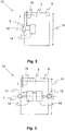
- FIG. 2 shows a schematic front view of a maintenance device 13 with a pivotable operating component 14.
- the operating component 14 is, as symbolized by an arrow, to provide a first, perpendicular to the travel direction 4 (see FIG. Figure 1 ) oriented pivot axis 6 pivotable in order to move the maintenance device 13 from its maintenance position I shown here into its inspection position II, not shown here.
- the operating component 14 is fastened to the operating unit 2 by means of a swivel joint 12.
- a device 16 for energy supply is shown, which supplies the operating unit 14 with electricity and / or compressed air and / or negative pressure.
- the operating component 14 can be pivoted into the inspection position II without any problems without loading the supply lines of the device 16 for energy supply.
- several operating components 14 can each be arranged individually pivotable on the operating unit 2.
- the pivot axis 6 does not run on the lateral edge of the operating unit, as shown here, but, for example, in a central area.
- FIG. 3 shows another embodiment of a maintenance device 13 with a pivotable operating component 14.
- two operating components 14 are provided, which are arranged around a second, parallel to the travel direction 4 (see FIG. Figure 1 ) aligned pivot axis 7 are pivotable (see arrow).
- the device 16 for supplying energy is located near the pivot axis 7.
- the pivot axis 7 is arranged essentially in the center of the operating components 14, but the pivot axis 7 could also be arranged at a lower or upper end of the operating components 14 so that they can be folded up or down from the operating unit 2.
- the pivot axis 7 could of course also be arranged at a different point in relation to the height H of the maintenance device 13.
- more or fewer operating components 14 can also be provided on the operating unit 2 in this embodiment.
- FIGS. 2 and 3 show operating units 14, which either move by a parallel to the direction of travel 4 (see Fig. Figure 1 ) aligned pivot axis 7 or are pivotable about a pivot axis 6 aligned perpendicular thereto.
- the operating components 14 or only a part of the operating components 14 can also be pivotable about two different pivot axes 6, 7.
- the operating components 14 of an operating unit 2 also do not necessarily have to be pivotable about the same pivot axis 6, 7 but each operating component 14 can also have its own pivot axis 6, 7.
- Figure 4 shows a further maintenance device 13 in a schematic front view.
- the operating components 14 of the operating unit 2 are arranged on a common carrier 15, which in turn can be pivoted relative to the operating unit 2 about a pivot axis 6 (see arrow) oriented perpendicular to the direction of travel 4 (see FIG. 1).
- the device 16 for the energy supply is in turn located near the pivot axis 6.
- a plurality of operating components 14 can be pivoted simultaneously from the maintenance position I shown here into the inspection position II, which is not shown, which simplifies the inspection and saves time.
- the pivot axis 6 could of course also be arranged here at another point, for example in the center of the operating unit 2.
- FIG. 5 also shows a maintenance device 13, the operating components 14 of which are arranged on a common carrier 15.
- the carrier 15 is, however, about a distance parallel to the direction of travel 4 (see Fig. Figure 1 ) aligned pivot axis 7 pivotable, as shown again by an arrow.
- the pivot axis 7 could also be arranged here at a different point in relation to the height H of the maintenance device 13.
- the carrier 15 can also be pivotable about both pivot axes 6, 7 or further operating components 14 can be present which are not arranged on the carrier 15, but are separately movable as in FIG Figures 2 and 3 or are firmly attached to the control unit 2.
- the in Figure 1 Maintenance facilities shown are advantageous when the device 16 for supplying energy is both in the maintenance position and in the inspection position is connected to the operating unit 2, which is facilitated by an arrangement of the device 16 near the pivot axis 6, 7.
- the guide unit 9 can of course also be designed in different ways and, for example, also extend over the entire height of the maintenance device 13 or have a frame on which the operating unit 2 is in turn arranged.
Landscapes
- Engineering & Computer Science (AREA)
- Mechanical Engineering (AREA)
- Textile Engineering (AREA)
- Spinning Or Twisting Of Yarns (AREA)
Description
Die vorliegende Erfindung betrifft eine Wartungseinrichtung zur Wartung von nebeneinander angeordneten Arbeitsstellen einer Textilmaschine, insbesondere einer Spinnmaschine, mit einer Bedieneinheit, welche wenigstens eine Bedienkomponente zur Wartung der Arbeitsstellen aufweist, und mit einer Führungseinheit, mittels welcher die Wartungseinrichtung auf einer Fahrschiene entlang der Arbeitsstellen verfahrbar ist und welche eine Verfahrrichtung der Wartungseinrichtung definiert. Dabei ist die Wartungseinrichtung aus einer Wartungsstellung, in der eine der Arbeitsstellen von der Wartungseinrichtung gewartet werden kann, in eine Inspektionsstellung, in der die Wartungseinrichtung inspiziert werden kann, verbringbar. Weiterhin betrifft die Erfindung eine entsprechende Textilmaschine mit einer Wartungseinrichtung.The present invention relates to a maintenance device for maintaining adjacent work stations of a textile machine, in particular a spinning machine, with an operating unit which has at least one operating component for maintaining the work stations, and with a guide unit by means of which the maintenance device can be moved on a running rail along the work stations and which defines a direction of travel of the maintenance facility. The maintenance device can be moved from a maintenance position in which one of the work stations can be serviced by the maintenance device into an inspection position in which the maintenance device can be inspected. The invention also relates to a corresponding textile machine with a maintenance device.
Aus der
Aus der
Aufgabe der vorliegenden Erfindung ist es somit, den Nachteil des Stands der Technik zu beheben.The object of the present invention is therefore to eliminate the disadvantage of the prior art.
Die Aufgabe wird gelöst durch eine Wartungseinrichtung und eine Textilmaschine mit den Merkmalen der unabhängigen Patentansprüche.The object is achieved by a maintenance device and a textile machine with the features of the independent patent claims.
Vorgeschlagen wird eine Wartungseinrichtung zur Wartung von Arbeitsstellen einer Textilmaschine, die auf einer Fahrschiene entlang der Arbeitsstellen verfahrbar ist, sowie eine entsprechende Textilmaschine mit einer solchen Wartungseinrichtung. Die Wartungseinrichtung fährt dabei beispielsweise bei einem Ausfall, zur Inspektion, zur Reinigung oder zur Reparatur einer Arbeitsstelle zu dieser hin, um eine entsprechende Tätigkeit an der Arbeitsstelle durchzuführen. Die Wartungseinrichtung umfasst hierzu eine Bedieneinheit, welche wenigstens eine Bedienkomponente zur Wartung der Arbeitsstellen aufweist. Weiterhin umfasst die Wartungseinrichtung eine Führungseinheit, mittels welcher die Wartungseinrichtung auf der Fahrschiene entlang der Arbeitsstellen verfahrbar ist und welche eine Verfahrrichtung der Wartungseinrichtung definiert. Die Führungseinheit kann beispielsweise Rollen umfassen, so dass die Wartungseinrichtung entlang der Fahrschiene verfahren werden kann. Die Anordnung der Rollen definiert dabei zugleich auch die Verfahrrichtung. Die Wartungseinrichtung ist dabei aus einer Wartungsstellung in eine Inspektionsstellung und zurück verbringbar. In der Wartungsstellung kann die angefahrene Arbeitsstelle von der Wartungseinrichtung gewartet werden. In der Inspektionsstellung kann dagegen die Wartungseinrichtung selbst inspiziert werden. Unter Inspektion der Wartungseinrichtung bzw. Wartung der Arbeitsstelle verstehen sich selbstverständlich auch Tätigkeiten wie beispielsweise das Reinigen, das Reparieren und/oder ein Beheben eines Fehlers oder eine andere Tätigkeit, die an und/oder von der Wartungseinrichtung durchgeführt werden soll.A maintenance device is proposed for the maintenance of workplaces of a textile machine, which can be moved on a running rail along the workplaces, and a corresponding textile machine with such a maintenance device. In this case, for example, in the event of a failure, for inspection, cleaning or repair of a work site, the maintenance device moves to this in order to carry out a corresponding activity at the work site. For this purpose, the maintenance device comprises an operating unit which has at least one operating component for maintaining the workstations. Furthermore, the maintenance device comprises a guide unit, by means of which the maintenance device can be moved on the running rail along the work stations and which defines a direction of movement of the maintenance device. The guide unit can for example comprise rollers so that the maintenance device can be moved along the running rail. The arrangement of the rollers also defines the direction of travel. The maintenance device can be moved from a maintenance position to an inspection position and back. In the maintenance position, the work site approached can be serviced by the maintenance facility. In the inspection position, on the other hand, the maintenance device itself can be inspected. Inspection of the maintenance facility or maintenance of the work site naturally also includes activities such as cleaning, repairing and / or rectifying a Error or other activity that should be carried out on and / or by the maintenance facility.
Es ist vorgesehen, dass zum Verbringen der Wartungseinrichtung von der Wartungsstellung in die Inspektionsstellung die wenigstens eine Bedienkomponente gegenüber der Bedieneinheit bewegbar, insbesondere verschwenkbar ist. Dadurch kann die Fahrschiene ebenso wie die Führungseinheit während des Verschwenkens an der Spinnmaschine verbleiben, so dass diese einfach konstruiert werden können. Die Fahrschiene bzw. die Textilmaschine muss keine gesonderte Serviceposition oder sonstige Vorkehrungen aufweisen, um die Wartungseinrichtung in ihre Wartungsstellung zu verbringen. Ebenso ist es nicht erforderlich, die Wartungseinrichtung von der Textilmaschine abzunehmen, um diese zu inspizieren. Durch das Bewegen der wenigstens einen Bedienkomponente kann das Bedienpersonal die Wartungseinrichtung bzw. deren Bedienkomponente(n) in einfacher Weise von mehreren, vorzugsweise von allen, Seiten erreichen, um die Wartungseinrichtung vollständig zu inspizieren. Vorteilhaft ist es dabei auch, dass die Wartungseinrichtung an jeder beliebigen Position an der Textilmaschine inspiziert werden kann und nicht erst in eine bestimmte Serviceposition bspw. an einem der Enden der Textilmaschine verbracht werden muss. Nach der Inspektion der Wartungseinrichtung kann diese selbstverständlich wieder zurück in die Wartungsstellung gebracht werden.It is provided that, in order to move the maintenance device from the maintenance position into the inspection position, the at least one operating component can be moved, in particular pivoted, with respect to the operating unit. As a result, the running rail, as well as the guide unit, can remain on the spinning machine during the pivoting, so that these can be constructed simply. The running rail or the textile machine does not have to have a separate service position or other precautions in order to bring the maintenance device into its maintenance position. It is also not necessary to remove the maintenance device from the textile machine in order to inspect it. By moving the at least one operating component, the operating personnel can reach the maintenance device or its operating component (s) in a simple manner from several, preferably from all, sides in order to completely inspect the maintenance device. It is also advantageous that the maintenance device can be inspected at any position on the textile machine and does not first have to be brought to a specific service position, for example at one of the ends of the textile machine. After the maintenance facility has been inspected, it can of course be returned to the maintenance position.
Des Weiteren ist es von Vorteil, wenn die wenigstens eine Bedienkomponente zur Inspektion von der Wartungsstellung in die Inspektionsstellung von der Bedieneinheit weg bewegbar, bspw. mittels eines Gestänges ausziehbar ist. Die Bedienkomponente kann damit zur Inspektion von der Arbeitsstelle weg gezogen werden, so dass das Personal die Komponente in einfacher Weise inspizieren kann. Ist die wenigstens eine Bedienkomponente der Wartungseinrichtung gegenüber der Bedieneinheit schwenkbar, so vereinfacht dies die Inspektion der Wartungseinrichtung bzw. der zu inspizierenden einzelnen Bedienkomponenten ebenfalls. Die einzelnen Bedienkomponenten können dabei von der Wartungsstellung, in der sie die Arbeitsstellen warten können, in die Inspektionsstellung, in der sie selbst inspiziert werden können, geschwenkt werden, wobei mehrere Bedienkomponenten gemeinsam oder auch nur eine Bedienkomponente für sich verschwenkt werden kann. Auch eine Kombination aus einer verschwenkbaren Bedieneinheit und einer oder mehreren zusätzlich gegenüber der Bedieneinheit bewegbaren Bedienkomponenten ist denkbar.Furthermore, it is advantageous if the at least one operating component can be moved away from the operating unit for inspection from the maintenance position into the inspection position, for example by means of a linkage. The operating component can thus be pulled away from the workplace for inspection so that the personnel can inspect the component in a simple manner. If the at least one operating component of the maintenance device can be pivoted with respect to the operating unit, this also simplifies the inspection of the maintenance device or the individual operating components to be inspected. The individual operating components can can be pivoted from the maintenance position, in which you can maintain the work stations, into the inspection position, in which you can be inspected yourself, whereby several operating components can be pivoted together or only one operating component can be pivoted separately. A combination of a pivotable operating unit and one or more operating components which can also be moved relative to the operating unit is also conceivable.
Vorteilhafterweise wird die wenigstens eine Bedienkomponente mittels eines Drehgelenks gegenüber der Führungseinheit bzw. gegenüber der Bedieneinheit verschwenkt. Das Drehgelenk kann beispielsweise ein Scharnier sein.The at least one operating component is advantageously pivoted relative to the guide unit or relative to the operating unit by means of a swivel joint. The swivel joint can be a hinge, for example.
Ferner ist es von Vorteil, wenn die einzelne Bedienkomponente um eine zur Verfahrrichtung senkrechte erste Schwenkachse schwenkbar ist. Da die Arbeitsstellen in der Regel nebeneinander angeordnet sind, ist somit die Verfahrrichtung zumeist waagrecht orientiert. Die erste Schwenkachse ist sodann eine Vertikale, um die die einzelne Bedienkomponente geschwenkt wird. Die einzelnen Bedienkomponenten werden dabei beispielsweise ähnlich einer Tür aufgeschwenkt und sind dann bequem vom Personal erreichbar.It is also advantageous if the individual operating component can be pivoted about a first pivot axis perpendicular to the direction of travel. Since the work stations are usually arranged next to one another, the direction of travel is therefore mostly horizontal. The first pivot axis is then a vertical one about which the individual operating component is pivoted. The individual operating components are swung open like a door, for example, and are then easily accessible by staff.
Ebenfalls ist es vorteilhaft, wenn die Bedienkomponente um eine zweite Schwenkachse schwenkbar ist. Die zweite Schwenkachse ist dabei zur Verfahrrichtung parallel ausgerichtet. Die einzelne(n) Bedienkomponente(n) können dadurch nach oben oder nach unten von den Arbeitsstellen weg geklappt werden, so dass die Bedienkomponente(n) vom Personal erreichbar ist bzw. sind.It is also advantageous if the operating component can be pivoted about a second pivot axis. The second pivot axis is aligned parallel to the direction of travel. The individual operating component (s) can thereby be folded up or down away from the workstations, so that the operating component (s) can be reached by staff.
Weiterhin ist es vorteilhaft, wenn die Bedieneinheit mehrere Bedienkomponenten aufweist, welche zur Inspektion gemeinsam bewegbar gegenüber der Bedieneinheit an der Wartungseinrichtung angeordnet sind. Dabei sind die mehreren Bedienkomponenten vorzugsweise an einem gemeinsamen Träger angeordnet. Es können somit in zeitsparender Weise mehrere Bedienkomponenten auf einmal in die Inspektionsstellung verbracht und inspiziert werden.Furthermore, it is advantageous if the operating unit has a plurality of operating components which, for the purpose of inspection, are arranged to be movable together with respect to the operating unit on the maintenance device. The several operating components are preferably on a common carrier arranged. A number of operating components can thus be brought into the inspection position and inspected at once in a time-saving manner.
Ebenfalls vorteilhaft ist es, wenn die Wartungseinrichtung eine Einrichtung zur Energieversorgung umfasst, welche in der Wartungsstellung und in der Inspektionsstellung der Wartungseinrichtung mit der Bedieneinheit und/oder deren wenigstens einen Bedienkomponente verbunden ist. Es kann somit in der Inspektionsstellung auch die Funktion der Bedieneinheit bzw. der wenigstens einen Bedienkomponente überprüft werden. Ebenso ist es dadurch möglich, bestimmte Einstellungen von Bedienkomponenten vorzunehmen. Die Einrichtung zur Energieversorgung kann beispielsweise elektrische Versorgungsleitungen und/oder Druckluftversorgungsleitungen und/oder Unterdruckversorgungsleitungen umfassen. Ein Anschluss der Versorgungsleitungen ist dabei vorzugsweise fest an der Wartungseinrichtung angeordnet. Es kann dabei jedoch vorgesehen sein, dass einzelne Versorgungsleitungen beweglich an der Bedieneinheit, einer Bedienkomponente oder einem Träger angeordnet sind, um das Bewegen der Bedieneinheit oder Bedienkomponente zu ermöglichen.It is also advantageous if the maintenance device comprises a device for power supply which is connected to the operating unit and / or its at least one operating component in the maintenance position and in the inspection position of the maintenance device. The function of the operating unit or the at least one operating component can thus also be checked in the inspection position. It is also possible to make certain settings for operating components. The device for the energy supply can for example comprise electrical supply lines and / or compressed air supply lines and / or negative pressure supply lines. A connection for the supply lines is preferably permanently arranged on the maintenance device. It can, however, be provided that individual supply lines are movably arranged on the operating unit, an operating component or a carrier in order to enable the operating unit or operating component to be moved.
Weiterhin ist es vorteilhaft, wenn die Wartungseinrichtung eine Sicherheitsvorrichtung zur Kollisionsvermeidung umfasst, welche sowohl in der Wartungsstellung als auch bei sich in der Inspektionsstellung befindender Wartungseinrichtung wirksam ist. Die Sicherheitsvorrichtung kann beispielsweise als Umkehrbügel ausgeführt sein, welcher sich in Verfahrrichtung von der Wartungseinrichtung weg erstreckt. Trifft der Umkehrbügel während des Verfahrens der Wartungseinrichtung auf ein Hindernis oder wird der Umkehrbügel durch ein herankommendes, bewegtes Hindernis getroffen oder in sonstiger Weise betätigt, so wird in an sich bekannter Weise beispielsweise die Fahrtrichtung umgekehrt und oder der Fahrantrieb blockiert, um eine Kollision zu vermeiden. Diese Sicherheitsfunktion bleibt auch bei sich in der Inspektionsstellung befindender Wartungseinrichtung gewährleistet. Ist die Sicherheitsvorrichtung als Umkehrbügel ausgeführt, so wird dieser an dem ersten Wartungseinrichtungsteil angeordnet und somit beim Verschwenken des zweiten Wartungseinrichtungsteils nicht mit verschwenkt.Furthermore, it is advantageous if the maintenance device comprises a safety device for collision avoidance, which is effective both in the maintenance position and when the maintenance device is in the inspection position. The safety device can be designed, for example, as a reversing bracket which extends away from the maintenance device in the direction of travel. If the reversing bar encounters an obstacle while the maintenance facility is moving, or if the reversing bar is hit by an approaching moving obstacle or actuated in any other way, the direction of travel is reversed and / or the drive is blocked in a known manner in order to avoid a collision . This safety function is also guaranteed when the maintenance facility is in the inspection position. Is the safety device designed as a reversing bracket, this is arranged on the first maintenance device part and is therefore not pivoted when the second maintenance device part is pivoted.
Zusätzlich oder alternativ ist es aber auch denkbar, dass die Wartungseinrichtung eine Sicherheitsvorrichtung zur Kollisionsvermeidung umfasst, welche durch das Verbringen der Wartungseinrichtung von der Wartungsstellung in die Inspektionsstellung vorzugsweise automatisch aktivierbar ist.Additionally or alternatively, however, it is also conceivable that the maintenance device comprises a safety device for collision avoidance, which can preferably be activated automatically by moving the maintenance device from the maintenance position to the inspection position.
Vorteilhaft ist es auch, wenn die Wartungseinrichtung eine Sicherheitsvorrichtung umfasst, mit deren Hilfe in der Inspektionsstellung der Wartungseinrichtung zumindest ein Teil der Wartungseinrichtung abschaltbar ist. Dabei kann die Sicherheitsvorrichtung die Wartungseinrichtung und/oder die einzelnen Bedienkomponenten beispielsweise stromlos schalten, so dass bei der Inspektion Verletzungen beim Personal verhindert werden können. Ebenso kann beispielsweise der Fahrantrieb der Wartungseinrichtung deaktiviert werden, um Verletzungen von Personen und Beschädigungen der Bedieneinheit oder der Bedienkomponente(n) zu vermeiden.It is also advantageous if the maintenance device comprises a safety device, with the aid of which at least part of the maintenance device can be switched off in the inspection position of the maintenance device. In this case, the safety device can switch the maintenance device and / or the individual operating components to a currentless state, for example, so that injuries to personnel can be prevented during the inspection. Likewise, for example, the drive of the maintenance facility can be deactivated in order to avoid injuries to persons and damage to the operating unit or the operating component (s).
Ebenso ist es von Vorteil, wenn die Wartungseinrichtung wenigstens einen Aktor aufweist, mittels dem die Bedienkomponente schwenkbar und/oder bewegbar ist. Dadurch wird das Bewegen der Bedieneinheit und/oder der Bedienkomponente vereinfacht. Der Aktor kann dabei beispielsweise einen Elektromotor umfassen.It is also advantageous if the maintenance device has at least one actuator, by means of which the operating component can be pivoted and / or moved. This simplifies the movement of the operating unit and / or the operating component. The actuator can include, for example, an electric motor.
Des Weiteren ist es von Vorteil, wenn ein Winkel zwischen der Inspektions- und der Wartungsstellung zwischen 45° und 180° beträgt. Dadurch kann die Wartungseinrichtung und/oder die Bedienkomponente einfach erreicht werden.Furthermore, it is advantageous if an angle between the inspection and maintenance positions is between 45 ° and 180 °. As a result, the maintenance device and / or the operating component can be easily reached.
Weitere Vorteile der Erfindung sind in den nachfolgenden Ausführungsbeispielen beschrieben. Es zeigen:
-
Figur 1 - eine Draufsicht auf einen Ausschnitt einer Textilmaschine mit einer Fahrschiene und mehreren Wartungseinrichtungen,
-
Figur 2 - eine schematische Vorderansicht einer Wartungseinrichtung mit einer schwenkbaren Bedienkomponente,
- Figur 3
- eine schematische Vorderansicht einer Wartungseinrichtung mit schwenkbaren Bedienkomponenten nach einer anderen Ausführung,
-
Figur 4 - eine schematische Vorderansicht einer Wartungseinrichtung mit schwenkbaren, auf einem Träger angeordneten Bedienkomponenten, sowie
-
Figur 5 - eine schematische Vorderansicht einer Wartungseinrichtung mit schwenkbaren, auf einem Träger angeordneten Bedienkomponenten nach einer anderen Ausführung.
- Figure 1
- a top view of a section of a textile machine with a rail and several maintenance facilities,
- Figure 2
- a schematic front view of a maintenance facility with a pivotable operating component,
- Figure 3
- a schematic front view of a maintenance facility with pivotable operating components according to another embodiment,
- Figure 4
- a schematic front view of a maintenance device with pivotable operating components arranged on a carrier, as well as
- Figure 5
- a schematic front view of a maintenance device with pivotable operating components arranged on a carrier according to another embodiment.
Die Fahrschienen 3a, 3b können außerdem auch mittels eines Rundbogens zu einer einzigen Fahrschiene 3 verbunden sein, die sich auf zumindest einer Querseite der Textilmaschine 1 um diese herum erstreckt. Vorliegend handelt es sich bei den Fahrschienen 3a, 3b jedoch um zwei getrennte Fahrschienen 3a, 3b, wobei jeweils eine Fahrschiene 3a, 3b an jeweils einer Längsseite der Textilmaschine 1 angeordnet ist. Die Fahrschienen 3a, 3b sind dabei fest mit der Textilmaschine 1 verbunden und verbleiben während einer Wartung der Wartungseinrichtungen 13a-13e an der Textilmaschine 1.The running
An der Fahrschiene 3a sind in diesem Ausführungsbeispiel drei Wartungseinrichtungen 13a-13c in einer Verfahrrichtung 4 entlang der Fahrschiene 3a nach beiden Seiten hin verfahrbar angeordnet. An der Fahrschiene 3b sind vorliegend zwei Wartungseinrichtungen 13d, 13e in der Verfahrrichtung 4 nach beiden Seiten verfahrbar angeordnet. Eine derartige Anordnung der Wartungseinrichtungen 13a-13e an den beiden Fahrschienen 3a, 3b ist nur beispielhaft gewählt. Die Textilmaschine 1 kann auch mehr oder weniger Wartungseinrichtungen 13a-13e aufweisen.In this exemplary embodiment, three
Die Wartungseinrichtungen 13a-13e weisen des Weiteren jeweils eine Führungseinheit 9 auf, die die Wartungseinrichtungen 13a-13e an den Fahrschienen 3a, 3b fixiert und mittels welcher die Wartungseinrichtungen 13a-13e auf den Fahrschienen 3a, 3b verfahrbar sind. Die Führungseinheit 9 definiert dabei die Verfahrrichtung 4 der Wartungseinrichtungen 13a-13e, beispielsweise durch die Art der Anordnung von Fahrrollen oder durch eine bestimmte Ausbildung der Führung, welche die Verfahrrichtung 4 vorgibt. Die Wartungseinrichtungen 13a-13e weisen jeweils eine Bedieneinheit 2a-2e auf, mittels welcher die Arbeitsstellen 11 der Textilmaschine 1 gewartet werden können. Die Bedieneinheiten 2a-2e weisen hierzu jeweils wenigstens eine Bedienkomponente 14 auf. Beispielsweise ist in vorliegender Darstellung die Wartungseinrichtung 13d zu einer zu wartenden Arbeitsstelle 11 gefahren und vor dieser platziert, um eine entsprechende Wartung, Reparatur oder eine ähnliche Tätigkeit an dieser Arbeitsstelle 11 auszuführen. Die Bedienkomponente 14 kann beispielsweise als Spulenwechsler, als Anspinnvorrichtung, als Reinigungsvorrichtung oder als ein Teil der genannten Vorrichtungen, beispielsweise als pneumatisches Fadenhandlingsorgan, als Fadenendenvorbereitungseinheit, als Rotorreinigungseinheit oder dgl. ausgebildet sein. Die Wartungseinrichtungen 13a-13e können die Arbeitsstellen 11 beispielsweise auch mittels einer Sauganlage reinigen.The
Da die Wartungseinrichtungen 13a-13e wenigstens eine, meist jedoch mehrere komplexe Bedienkomponenten 14 umfassen, müssen von Zeit zu Zeit die Wartungseinrichtungen 13a-13e selbst inspiziert, gewartet, gereinigt bzw. repariert werden. Dazu können die Wartungseinrichtungen 13a-13e von einer Wartungsstellung I in eine Inspektionsstellung II gebracht werden. In der Wartungsstellung I können die Wartungseinrichtungen 13a-13e die Arbeitsstellen 11 warten. In der Inspektionsstellung II können die Wartungseinrichtungen 13a-13e selbst inspiziert werden. Die Wartungseinrichtungen 13a und 13d sind hier beispielhaft in der Wartungsstellung I gezeigt. Die Wartungseinrichtungen 13a und 13d sind dabei nahe an der Textilmaschine 1 bzw. an den Arbeitsstellen 11 angeordnet. Die Wartungseinrichtungen 13b, 13c und 13e sind hingegen beispielhaft in jeweils einer speziellen Ausbildung der Inspektionsstellung II gezeigt.Since the
Die Wartungseinrichtung 13b ist beispielsweise in einer Inspektionsstellung II gezeigt, in welcher zumindest eine der Bedienkomponenten 14 aus der Bedieneinheit 2b herausgefahren ist, so dass diese für einen Bediener von mehreren Seiten aus zugänglich ist, um inspiziert zu werden. Die Bedienkomponente 14 ist hierzu in der Inspektionsstellung II um einen Abstand 5 zu ihrer gestrichelt dargestellten Wartungsstellung I verschoben. Die Wartungseinrichtung 13b kann hierzu beispielsweise ein Gestänge 10 aufweisen, mittels welchem die Bedienkomponente 14 gegenüber der Bedieneinheit 2b verfahrbar ist. Die wenigstens eine Bedienkomponente 14 oder auch mehrere Bedienkomponenten 14 können jedoch auch in anderer Weise mittels eines Gestänges 10 oder eines Drehgelenks 12 gegenüber der Wartungseinrichtung 13 bzw. der Bedieneinheit 2 bewegt werden, wie anhand der
Die Wartungseinrichtungen 13c, 13e sind in einer weiteren speziellen nicht beanspruchten Ausführungsform der Inspektionsstellung II gezeigt. Dabei sind die beiden Bedieneinheiten 2c, 2e jeweils um eine erste Schwenkachse 6, die sich senkrecht zur Verfahrrichtung 4 der Wartungseinrichtungen 13a-13e erstreckt, um einen Winkel 8 von ihrer Fahrschiene 3a, 3b weg geschwenkt. Die Bedieneinheiten 2c, 2e können dazu mittels eines Drehgelenks 12 gegenüber den Führungseinheiten 9 verschwenkt werden. Die Führungseinheiten 9 bleiben dabei an der Fahrschiene 3a, 3b angeordnet. Auch die Fahrschienen 3a, 3b bleiben fest an der Textilmaschine 1 angeordnet, so dass diese einfach ausgeführt werden können und keine Vorkehrungen benötigen, um die Wartungseinrichtungen 13a-13e in ihre Inspektionsstellung II zu verbringen. Auch in diesem nicht beanspruchten Ausführungsbeispiel kann das Personal die Wartungseinrichtungen 13c,13e und/oder die einzelnen Bedienkomponenten 14 einfach inspizieren, da auch deren im Betrieb der Textilmaschine 1 bzw. den Arbeitsstellen 11 zugewandte Seite zugänglich ist.The
Gemäß einer weiteren nicht beanspruchten Ausführungsform ist die Wartungseinrichtung 13d ebenfalls dadurch in ihre Inspektionsstellung II verbringbar, dass ihre Bedieneinheit 2d gegenüber der Führungseinheit 9 verschwenkbar ist. Die Bedieneinheit 2d kann dazu um eine zweite Schwenkachse 7 geschwenkt werden, die parallel zur Fahrschiene 3b bzw. zur Verfahrrichtung 4 ausgerichtet ist. Die Wartungseinrichtung 13d bzw. deren Bedieneinheit 2d kann dadurch beispielsweise nach oben oder nach unten geklappt werden oder lediglich um eine Mittelachse der Wartungseinrichtung 13d oder der Bedieneinheit 2d gedreht werden, um diese zu inspizieren. Die Schwenkachse 7 kann sich dabei bezogen auf eine Höhe H der Wartungseinrichtung 13 (die Höhe H ist lediglich beispielhaft in den
Das Schwenken der Bedieneinheit 2 gegenüber der Führungseinheit 9 um die erste Schwenkachse 6 oder die zweite Schwenkachse 7 wurde dabei anhand der Wartungseinrichtungen 13c, 13d nur beispielhaft erläutert. Denkbar ist es natürlich auch, dass eine Bedieneinheit 2 sowohl um eine erste Schwenkachse 6 als auch um eine zweite Schwenkachse 7 verschwenkbar ist, um die Zugänglichkeit der Bedienkomponenten 14 zu verbessern. Daneben ist es natürlich ebenso denkbar, eine gegenüber der Führungseinheit 9 verschwenkbare Bedieneinheit 2 mit einer oder mehreren separat gegenüber der Bedieneinheit 2 bewegbaren Bedienkomponenten 14, wie sie in den Figuren 2-5 dargestellt sind, zu kombinieren. Vorteilhaft bei einem Schwenken der Bedieneinheit 2 ist es in jedem Fall, dass eine Einrichtung zur Energieversorgung 16 (s.
Die
Die vorliegende Erfindung ist nicht auf die dargestellten und beschriebenen Ausführungsbeispiele beschränkt. So sind insbesondere bezüglich der Position der Schwenkachsen 6, 7 zahlreiche Variationen möglich. Weiterhin könnte mit Bezug auf die
Weitere Abwandlungen im Rahmen der Patentansprüche sind ebenso möglich wie eine Kombination der Merkmale, auch wenn diese in unterschiedlichen Ausführungsbeispielen dargestellt und beschrieben sind.Further modifications within the scope of the patent claims are just as possible as a combination of the features, even if these are shown and described in different exemplary embodiments.
- 11
- TextilmaschineTextile machine
- 22
- BedieneinheitControl unit
- 33
- FahrschieneRunway
- 44th
- VerfahrrichtungDirection of travel
- 55
- Abstanddistance
- 66
- erste Schwenkachsefirst pivot axis
- 77th
- zweite Schwenkachsesecond pivot axis
- 88th
- Winkelangle
- 99
- FührungseinheitGuide unit
- 1010
- GestängeLinkage
- 1111
- Arbeitsstelleplace of work
- 1212th
- DrehgelenkSwivel
- 1313th
- WartungseinrichtungMaintenance facility
- 1414th
- BedienkomponenteOperating component
- 1515
- Trägercarrier
- 1616
- Einrichtung zur EnergieversorgungEnergy supply facility
- II.
- WartungsstellungMaintenance position
- IIII
- InspektionsstellungInspection position
- HH
- Höhe der WartungseinrichtungMaintenance facility height
Claims (10)
- Maintenance device (13a-13e) for servicing adjacent work stations (11) of a textile machine (1), in particular a spinning machine, comprising an operating unit (2a-2e), which features at least one operating component (14) for servicing the work stations (11), and with a guide unit (9), by means of which the maintenance device (13) can be moved on a driving rail (3) along the work stations (11) and which defines a direction of travel (4) of the maintenance device (13), whereas the maintenance device (13) can be transported from a maintenance position (I), in which one of the work stations (11) can be serviced by the maintenance device (13a-13e), into an inspection position (II), in which the maintenance device (13a-13e) can be inspected, characterized in that, for the transport of the maintenance device (13a-13e) from the maintenance position (I) into the inspection position (II), the operating unit (2a-2e) can be pivoted with respect to the guide unit (9), and/or the at least one operating component (14) can be moved (in particular, can be pivoted) with respect to the operating unit (2a-2e).
- Maintenance device according to the preceding claim, characterized in that the at least one operating component (14) can be pivoted by means of a swivel joint (12).
- Maintenance device according to one or more of the preceding claims, characterized in that the at least one operating component (14) can be pivoted around a first pivot axis (6), which is perpendicular to the direction of travel (4) and/or can be pivoted around a second pivot axis (7), which is aligned parallel to the direction of travel (4).
- Maintenance device according to one or more of the preceding claims, characterized in that the operating unit (2a-2e) features a multiple number of operating components (14), which, for the purpose of inspection, are arranged on the maintenance device (13a-13e) so as to be movable together with respect to the operating unit (2a-2e), whereas the multiple number of operating components (14) are preferably arranged on a common carrier (15).
- Maintenance device according to one or more of the preceding claims, characterized in that the maintenance device (13a-13e) comprises a device for the supply of energy (16), which is connected to the operating unit (2a-2e) in the maintenance position (I) and in the inspection position (II).
- Maintenance device according to one or more of the preceding claims, characterized in that if the maintenance device (13a-13e) comprises a safety device for avoiding collisions, in particular a reversing bracket, and that the safety device is effective even with the maintenance device (13a - 13e) located in the inspection position (II).
- Maintenance device according to one or more of the preceding claims, characterized in that the maintenance device (13a-13e) comprises a safety device for avoiding collisions, which can be activated through the transport of the maintenance device (13a-13e) from the maintenance position (I) into the inspection position (II).
- Maintenance device according to one or more of the preceding claims, characterized in that the maintenance device (13a-13e) comprises a safety device, with the assistance of which at least one part of the maintenance device (13a-13e) can be switched off in the inspection position (II) of the maintenance device (13a-13e).
- Maintenance device according to one or more of the preceding claims, characterized in that the maintenance device (13a-13e) features one actuator, by means of which the operating unit (2a-2e) and/or the at least one operating component (14) can be pivoted and/or moved.
- Textile machine (1), in particular a spinning machine, with a multiple number of similar work stations (11) arranged side by side and with at least one maintenance device (13a-13e) according to one of the preceding claims.
Applications Claiming Priority (1)
| Application Number | Priority Date | Filing Date | Title |
|---|---|---|---|
| DE102016116006.7A DE102016116006A1 (en) | 2016-08-29 | 2016-08-29 | Maintenance device for servicing workstations of a textile machine and textile machine |
Publications (2)
| Publication Number | Publication Date |
|---|---|
| EP3290550A1 EP3290550A1 (en) | 2018-03-07 |
| EP3290550B1 true EP3290550B1 (en) | 2020-08-12 |
Family
ID=59699612
Family Applications (1)
| Application Number | Title | Priority Date | Filing Date |
|---|---|---|---|
| EP17187783.0A Active EP3290550B1 (en) | 2016-08-29 | 2017-08-24 | Maintenance device for the maintenance of the work stations of a textile machine and textile machine |
Country Status (4)
| Country | Link |
|---|---|
| US (1) | US10480102B2 (en) |
| EP (1) | EP3290550B1 (en) |
| CN (1) | CN107794613B (en) |
| DE (1) | DE102016116006A1 (en) |
Family Cites Families (27)
| Publication number | Priority date | Publication date | Assignee | Title |
|---|---|---|---|---|
| US489450A (en) * | 1893-01-10 | Air-filtering apparatus | ||
| US3651628A (en) * | 1970-09-10 | 1972-03-28 | Maremont Corp | Supporting means for automatic yarn piecing apparatus |
| FR2206395B1 (en) * | 1972-11-10 | 1975-11-07 | Mulhouse Alsa Const Meca | |
| US4192129A (en) * | 1975-10-16 | 1980-03-11 | Hans Stahlecker | Movable servicing device for a spinning machine, especially an open end spinning machine |
| US4275554A (en) * | 1979-12-05 | 1981-06-30 | Platt Saco Lowell Limited | Clearance-producing means for open-end spinning machine servicing apparatus |
| GB2140553B (en) * | 1983-05-24 | 1988-03-23 | Rieter Ag Maschf | Automat location system |
| CN1026807C (en) * | 1984-11-15 | 1994-11-30 | 舒伯特-萨尔泽机械制造股份公司 | Method and device for yarn piecing in open-end spinning device |
| DE3602961A1 (en) | 1986-01-31 | 1987-08-13 | Schubert & Salzer Maschinen | METHOD AND DEVICE FOR MAINTAINING THE WORKSTATIONS OF SPINNING OR TWINING MACHINES BY MEANS OF MORE AT THE WORKSTATIONS ALONG MOBILE MAINTENANCE DEVICES |
| DE3734568A1 (en) * | 1987-10-13 | 1989-05-03 | Schubert & Salzer Maschinen | SPINNING MACHINE WITH A DEVICE FOR MAINTAINING SPINNING AND SPOOLS |
| DE58902921D1 (en) * | 1988-02-09 | 1993-01-21 | Rieter Ag Maschf | METHOD AND DEVICE FOR REPLACING PRE-YARN SPOOLS ON A RING SPIDER. |
| DE59008796D1 (en) * | 1989-10-03 | 1995-05-04 | Rieter Ag Maschf | Docking device with coupling sensor system. |
| EP0556528A1 (en) * | 1992-02-14 | 1993-08-25 | Carlos Pujol-Isern | Continuous centrifugal spinning method and spinning machine for carrying out the method |
| US7257878B2 (en) * | 1995-11-06 | 2007-08-21 | Beat Locher | Continuous cable processing apparatus |
| DE19930644A1 (en) * | 1999-07-02 | 2001-01-04 | Rieter Ingolstadt Spinnerei | Service unit running on rails along textile machine comprises a robotic unit mounted on a trolley so that it can be moved outwards for inspection |
| DE10130467B4 (en) * | 2001-06-23 | 2014-02-13 | Rieter Ingolstadt Gmbh | Arrangement of service positions for maintenance equipment on a textile machine |
| ITMI20021605A1 (en) * | 2001-07-28 | 2004-01-22 | Rieter Ingolstadt Spinnerei | RUNNING MOVEMENT CONTROL OF AT LEAST ONE MAINTENANCE DEVICE IN A TEXTILE MACHINE |
| DE10157760A1 (en) * | 2001-11-27 | 2003-06-05 | Hauni Maschinenbau Ag | Device for the production of rod-shaped objects |
| ITMI20032003A1 (en) * | 2003-10-16 | 2005-04-17 | Savio Macchine Tessili Spa | TRAVEL SERVICE DEVICE FOR OPEN-END YARN SPINNING UNITS |
| DE102004050738B4 (en) * | 2004-10-19 | 2012-12-27 | Rieter Ingolstadt Gmbh | Method for storing and replacing bobbins for providing yarn to the maintenance device of a textile machine and textile machine |
| DE102006007922A1 (en) | 2006-02-21 | 2007-08-30 | Saurer Gmbh & Co. Kg | Rail-mounted service unit for textile assembly cross-winding station has lifting eyes for removal and replacement |
| CN201713625U (en) * | 2009-12-08 | 2011-01-19 | 青岛东佳纺机(集团)有限公司 | Automatic can exchanging mechanism of can coiler |
| DE102010001475A1 (en) | 2010-02-02 | 2011-08-04 | Rieter Ingolstadt GmbH, 85055 | Maintenance device for a textile machine |
| JP2013067466A (en) * | 2011-09-21 | 2013-04-18 | Murata Machinery Ltd | Yarn processing device, spinning unit, and spinning machine |
| DE102012008706A1 (en) * | 2012-04-28 | 2013-10-31 | Oerlikon Textile Gmbh & Co. Kg | Service wagon for e.g. transporting operating assemblies movable along work locations of open end-rotor spinning machine producing cross-wound bobbins, has platform limitedly tiltable in direction of machine such that assemblies are lifted |
| CN202688562U (en) * | 2012-08-01 | 2013-01-23 | 浙江日发纺织机械股份有限公司 | Open-end spinning joint dolly joint device |
| CN108842239B (en) * | 2018-08-27 | 2023-08-29 | 国机智能技术研究院有限公司 | Method for splicing by using automatic splicing robot of ring spinning frame |
| CN209722407U (en) * | 2019-01-30 | 2019-12-03 | 吐鲁番常新纺织有限公司 | A kind of touring car positioning of improved open-end spinning frame |
-
2016
- 2016-08-29 DE DE102016116006.7A patent/DE102016116006A1/en not_active Withdrawn
-
2017
- 2017-08-24 EP EP17187783.0A patent/EP3290550B1/en active Active
- 2017-08-25 CN CN201710742929.5A patent/CN107794613B/en active Active
- 2017-08-29 US US15/689,212 patent/US10480102B2/en active Active
Non-Patent Citations (1)
| Title |
|---|
| None * |
Also Published As
| Publication number | Publication date |
|---|---|
| DE102016116006A1 (en) | 2018-03-01 |
| US20180057967A1 (en) | 2018-03-01 |
| CN107794613B (en) | 2021-08-06 |
| EP3290550A1 (en) | 2018-03-07 |
| CN107794613A (en) | 2018-03-13 |
| US10480102B2 (en) | 2019-11-19 |
Similar Documents
| Publication | Publication Date | Title |
|---|---|---|
| EP3188987B1 (en) | Automated rack storage system and method for safely operating it | |
| EP2731902B1 (en) | Scissors lift and method for constructing a scissors lift | |
| EP2387487B1 (en) | Robot system for laying a rail track | |
| DE4110427C2 (en) | Funding | |
| EP1100643A2 (en) | Method and device for cutting to length strips or sheets in the rolling or transport line | |
| DE3834583A1 (en) | TRANSPORT DEVICE FOR WORKPIECES | |
| EP3877310A1 (en) | Elevator system and method for operating an elevator system with an auxiliary device | |
| WO1997037564A1 (en) | Safety device for a storage device | |
| DE19930644A1 (en) | Service unit running on rails along textile machine comprises a robotic unit mounted on a trolley so that it can be moved outwards for inspection | |
| EP2117978A2 (en) | Device for removing containers from a container treatment installation | |
| DE102017116718A1 (en) | Processing plant for aircraft structural components | |
| EP3290550B1 (en) | Maintenance device for the maintenance of the work stations of a textile machine and textile machine | |
| DE3414387A1 (en) | DEVICE FOR AUTOMATICALLY CONVEYING TENSIONER FRAME OR THE LIKE, ESPECIALLY IN TRANSFER ROADS | |
| DE10130467B4 (en) | Arrangement of service positions for maintenance equipment on a textile machine | |
| DE102017104751B4 (en) | transport device | |
| WO2020035388A1 (en) | Elevator system | |
| DE202017005428U1 (en) | Maintenance track system | |
| EP2786912B1 (en) | Holding device for bogies | |
| EP3428115B1 (en) | Lifting device and method for moving a lifting carriage | |
| EP3165636A1 (en) | Stretching device | |
| EP1748855A1 (en) | Device for the stepped displacement of workpieces | |
| EP2792602A1 (en) | Labelling machine with switch cabinet | |
| EP3754444B1 (en) | Method for changing an aggregate on a packaging line and packaging line designed for this | |
| DE202013104581U1 (en) | Accumulation conveyor | |
| EP3290551A1 (en) | Running rail for a maintenance device for the maintenance of workplaces of a spinning machine and spinning machines |
Legal Events
| Date | Code | Title | Description |
|---|---|---|---|
| PUAI | Public reference made under article 153(3) epc to a published international application that has entered the european phase |
Free format text: ORIGINAL CODE: 0009012 |
|
| STAA | Information on the status of an ep patent application or granted ep patent |
Free format text: STATUS: THE APPLICATION HAS BEEN PUBLISHED |
|
| AK | Designated contracting states |
Kind code of ref document: A1 Designated state(s): AL AT BE BG CH CY CZ DE DK EE ES FI FR GB GR HR HU IE IS IT LI LT LU LV MC MK MT NL NO PL PT RO RS SE SI SK SM TR |
|
| AX | Request for extension of the european patent |
Extension state: BA ME |
|
| STAA | Information on the status of an ep patent application or granted ep patent |
Free format text: STATUS: REQUEST FOR EXAMINATION WAS MADE |
|
| 17P | Request for examination filed |
Effective date: 20180827 |
|
| RBV | Designated contracting states (corrected) |
Designated state(s): AL AT BE BG CH CY CZ DE DK EE ES FI FR GB GR HR HU IE IS IT LI LT LU LV MC MK MT NL NO PL PT RO RS SE SI SK SM TR |
|
| GRAP | Despatch of communication of intention to grant a patent |
Free format text: ORIGINAL CODE: EPIDOSNIGR1 |
|
| STAA | Information on the status of an ep patent application or granted ep patent |
Free format text: STATUS: GRANT OF PATENT IS INTENDED |
|
| INTG | Intention to grant announced |
Effective date: 20200507 |
|
| GRAS | Grant fee paid |
Free format text: ORIGINAL CODE: EPIDOSNIGR3 |
|
| GRAA | (expected) grant |
Free format text: ORIGINAL CODE: 0009210 |
|
| STAA | Information on the status of an ep patent application or granted ep patent |
Free format text: STATUS: THE PATENT HAS BEEN GRANTED |
|
| AK | Designated contracting states |
Kind code of ref document: B1 Designated state(s): AL AT BE BG CH CY CZ DE DK EE ES FI FR GB GR HR HU IE IS IT LI LT LU LV MC MK MT NL NO PL PT RO RS SE SI SK SM TR |
|
| REG | Reference to a national code |
Ref country code: CH Ref legal event code: EP |
|
| REG | Reference to a national code |
Ref country code: DE Ref legal event code: R096 Ref document number: 502017006687 Country of ref document: DE |
|
| REG | Reference to a national code |
Ref country code: IE Ref legal event code: FG4D Free format text: LANGUAGE OF EP DOCUMENT: GERMAN |
|
| REG | Reference to a national code |
Ref country code: AT Ref legal event code: REF Ref document number: 1301645 Country of ref document: AT Kind code of ref document: T Effective date: 20200915 |
|
| REG | Reference to a national code |
Ref country code: LT Ref legal event code: MG4D |
|
| REG | Reference to a national code |
Ref country code: NL Ref legal event code: MP Effective date: 20200812 |
|
| PG25 | Lapsed in a contracting state [announced via postgrant information from national office to epo] |
Ref country code: GR Free format text: LAPSE BECAUSE OF FAILURE TO SUBMIT A TRANSLATION OF THE DESCRIPTION OR TO PAY THE FEE WITHIN THE PRESCRIBED TIME-LIMIT Effective date: 20201113 Ref country code: FI Free format text: LAPSE BECAUSE OF FAILURE TO SUBMIT A TRANSLATION OF THE DESCRIPTION OR TO PAY THE FEE WITHIN THE PRESCRIBED TIME-LIMIT Effective date: 20200812 Ref country code: NO Free format text: LAPSE BECAUSE OF FAILURE TO SUBMIT A TRANSLATION OF THE DESCRIPTION OR TO PAY THE FEE WITHIN THE PRESCRIBED TIME-LIMIT Effective date: 20201112 Ref country code: HR Free format text: LAPSE BECAUSE OF FAILURE TO SUBMIT A TRANSLATION OF THE DESCRIPTION OR TO PAY THE FEE WITHIN THE PRESCRIBED TIME-LIMIT Effective date: 20200812 Ref country code: LT Free format text: LAPSE BECAUSE OF FAILURE TO SUBMIT A TRANSLATION OF THE DESCRIPTION OR TO PAY THE FEE WITHIN THE PRESCRIBED TIME-LIMIT Effective date: 20200812 Ref country code: BG Free format text: LAPSE BECAUSE OF FAILURE TO SUBMIT A TRANSLATION OF THE DESCRIPTION OR TO PAY THE FEE WITHIN THE PRESCRIBED TIME-LIMIT Effective date: 20201112 Ref country code: SE Free format text: LAPSE BECAUSE OF FAILURE TO SUBMIT A TRANSLATION OF THE DESCRIPTION OR TO PAY THE FEE WITHIN THE PRESCRIBED TIME-LIMIT Effective date: 20200812 |
|
| PG25 | Lapsed in a contracting state [announced via postgrant information from national office to epo] |
Ref country code: PL Free format text: LAPSE BECAUSE OF FAILURE TO SUBMIT A TRANSLATION OF THE DESCRIPTION OR TO PAY THE FEE WITHIN THE PRESCRIBED TIME-LIMIT Effective date: 20200812 Ref country code: NL Free format text: LAPSE BECAUSE OF FAILURE TO SUBMIT A TRANSLATION OF THE DESCRIPTION OR TO PAY THE FEE WITHIN THE PRESCRIBED TIME-LIMIT Effective date: 20200812 Ref country code: RS Free format text: LAPSE BECAUSE OF FAILURE TO SUBMIT A TRANSLATION OF THE DESCRIPTION OR TO PAY THE FEE WITHIN THE PRESCRIBED TIME-LIMIT Effective date: 20200812 Ref country code: LV Free format text: LAPSE BECAUSE OF FAILURE TO SUBMIT A TRANSLATION OF THE DESCRIPTION OR TO PAY THE FEE WITHIN THE PRESCRIBED TIME-LIMIT Effective date: 20200812 Ref country code: IS Free format text: LAPSE BECAUSE OF FAILURE TO SUBMIT A TRANSLATION OF THE DESCRIPTION OR TO PAY THE FEE WITHIN THE PRESCRIBED TIME-LIMIT Effective date: 20201212 |
|
| REG | Reference to a national code |
Ref country code: CH Ref legal event code: PL |
|
| PG25 | Lapsed in a contracting state [announced via postgrant information from national office to epo] |
Ref country code: CH Free format text: LAPSE BECAUSE OF NON-PAYMENT OF DUE FEES Effective date: 20200831 Ref country code: DK Free format text: LAPSE BECAUSE OF FAILURE TO SUBMIT A TRANSLATION OF THE DESCRIPTION OR TO PAY THE FEE WITHIN THE PRESCRIBED TIME-LIMIT Effective date: 20200812 Ref country code: CZ Free format text: LAPSE BECAUSE OF FAILURE TO SUBMIT A TRANSLATION OF THE DESCRIPTION OR TO PAY THE FEE WITHIN THE PRESCRIBED TIME-LIMIT Effective date: 20200812 Ref country code: RO Free format text: LAPSE BECAUSE OF FAILURE TO SUBMIT A TRANSLATION OF THE DESCRIPTION OR TO PAY THE FEE WITHIN THE PRESCRIBED TIME-LIMIT Effective date: 20200812 Ref country code: LU Free format text: LAPSE BECAUSE OF NON-PAYMENT OF DUE FEES Effective date: 20200824 Ref country code: LI Free format text: LAPSE BECAUSE OF NON-PAYMENT OF DUE FEES Effective date: 20200831 Ref country code: SM Free format text: LAPSE BECAUSE OF FAILURE TO SUBMIT A TRANSLATION OF THE DESCRIPTION OR TO PAY THE FEE WITHIN THE PRESCRIBED TIME-LIMIT Effective date: 20200812 Ref country code: EE Free format text: LAPSE BECAUSE OF FAILURE TO SUBMIT A TRANSLATION OF THE DESCRIPTION OR TO PAY THE FEE WITHIN THE PRESCRIBED TIME-LIMIT Effective date: 20200812 |
|
| REG | Reference to a national code |
Ref country code: DE Ref legal event code: R097 Ref document number: 502017006687 Country of ref document: DE |
|
| REG | Reference to a national code |
Ref country code: BE Ref legal event code: MM Effective date: 20200831 |
|
| PG25 | Lapsed in a contracting state [announced via postgrant information from national office to epo] |
Ref country code: ES Free format text: LAPSE BECAUSE OF FAILURE TO SUBMIT A TRANSLATION OF THE DESCRIPTION OR TO PAY THE FEE WITHIN THE PRESCRIBED TIME-LIMIT Effective date: 20200812 Ref country code: AL Free format text: LAPSE BECAUSE OF FAILURE TO SUBMIT A TRANSLATION OF THE DESCRIPTION OR TO PAY THE FEE WITHIN THE PRESCRIBED TIME-LIMIT Effective date: 20200812 Ref country code: MC Free format text: LAPSE BECAUSE OF FAILURE TO SUBMIT A TRANSLATION OF THE DESCRIPTION OR TO PAY THE FEE WITHIN THE PRESCRIBED TIME-LIMIT Effective date: 20200812 |
|
| PLBE | No opposition filed within time limit |
Free format text: ORIGINAL CODE: 0009261 |
|
| STAA | Information on the status of an ep patent application or granted ep patent |
Free format text: STATUS: NO OPPOSITION FILED WITHIN TIME LIMIT |
|
| PG25 | Lapsed in a contracting state [announced via postgrant information from national office to epo] |
Ref country code: SK Free format text: LAPSE BECAUSE OF FAILURE TO SUBMIT A TRANSLATION OF THE DESCRIPTION OR TO PAY THE FEE WITHIN THE PRESCRIBED TIME-LIMIT Effective date: 20200812 |
|
| 26N | No opposition filed |
Effective date: 20210514 |
|
| PG25 | Lapsed in a contracting state [announced via postgrant information from national office to epo] |
Ref country code: FR Free format text: LAPSE BECAUSE OF NON-PAYMENT OF DUE FEES Effective date: 20201012 |
|
| PG25 | Lapsed in a contracting state [announced via postgrant information from national office to epo] |
Ref country code: SI Free format text: LAPSE BECAUSE OF FAILURE TO SUBMIT A TRANSLATION OF THE DESCRIPTION OR TO PAY THE FEE WITHIN THE PRESCRIBED TIME-LIMIT Effective date: 20200812 Ref country code: IE Free format text: LAPSE BECAUSE OF NON-PAYMENT OF DUE FEES Effective date: 20200824 Ref country code: BE Free format text: LAPSE BECAUSE OF NON-PAYMENT OF DUE FEES Effective date: 20200831 |
|
| GBPC | Gb: european patent ceased through non-payment of renewal fee |
Effective date: 20210824 |
|
| PG25 | Lapsed in a contracting state [announced via postgrant information from national office to epo] |
Ref country code: MT Free format text: LAPSE BECAUSE OF FAILURE TO SUBMIT A TRANSLATION OF THE DESCRIPTION OR TO PAY THE FEE WITHIN THE PRESCRIBED TIME-LIMIT Effective date: 20200812 Ref country code: CY Free format text: LAPSE BECAUSE OF FAILURE TO SUBMIT A TRANSLATION OF THE DESCRIPTION OR TO PAY THE FEE WITHIN THE PRESCRIBED TIME-LIMIT Effective date: 20200812 |
|
| PG25 | Lapsed in a contracting state [announced via postgrant information from national office to epo] |
Ref country code: MK Free format text: LAPSE BECAUSE OF FAILURE TO SUBMIT A TRANSLATION OF THE DESCRIPTION OR TO PAY THE FEE WITHIN THE PRESCRIBED TIME-LIMIT Effective date: 20200812 |
|
| PG25 | Lapsed in a contracting state [announced via postgrant information from national office to epo] |
Ref country code: PT Free format text: LAPSE BECAUSE OF FAILURE TO SUBMIT A TRANSLATION OF THE DESCRIPTION OR TO PAY THE FEE WITHIN THE PRESCRIBED TIME-LIMIT Effective date: 20200812 Ref country code: GB Free format text: LAPSE BECAUSE OF NON-PAYMENT OF DUE FEES Effective date: 20210824 |
|
| P01 | Opt-out of the competence of the unified patent court (upc) registered |
Effective date: 20230329 |
|
| REG | Reference to a national code |
Ref country code: AT Ref legal event code: MM01 Ref document number: 1301645 Country of ref document: AT Kind code of ref document: T Effective date: 20220824 |
|
| PG25 | Lapsed in a contracting state [announced via postgrant information from national office to epo] |
Ref country code: AT Free format text: LAPSE BECAUSE OF NON-PAYMENT OF DUE FEES Effective date: 20220824 |
|
| PGFP | Annual fee paid to national office [announced via postgrant information from national office to epo] |
Ref country code: DE Payment date: 20250828 Year of fee payment: 9 |
|
| PGFP | Annual fee paid to national office [announced via postgrant information from national office to epo] |
Ref country code: TR Payment date: 20250730 Year of fee payment: 9 Ref country code: IT Payment date: 20250827 Year of fee payment: 9 |