EP3289812B1 - Method and apparatus for controlling communication of a portable terminal in a wireless communication system - Google Patents
Method and apparatus for controlling communication of a portable terminal in a wireless communication system Download PDFInfo
- Publication number
- EP3289812B1 EP3289812B1 EP16786789.4A EP16786789A EP3289812B1 EP 3289812 B1 EP3289812 B1 EP 3289812B1 EP 16786789 A EP16786789 A EP 16786789A EP 3289812 B1 EP3289812 B1 EP 3289812B1
- Authority
- EP
- European Patent Office
- Prior art keywords
- access
- enb
- module
- signal
- access module
- Prior art date
- Legal status (The legal status is an assumption and is not a legal conclusion. Google has not performed a legal analysis and makes no representation as to the accuracy of the status listed.)
- Active
Links
Images


Classifications
-
- H—ELECTRICITY
- H04—ELECTRIC COMMUNICATION TECHNIQUE
- H04W—WIRELESS COMMUNICATION NETWORKS
- H04W52/00—Power management, e.g. TPC [Transmission Power Control], power saving or power classes
- H04W52/02—Power saving arrangements
- H04W52/0209—Power saving arrangements in terminal devices
- H04W52/0212—Power saving arrangements in terminal devices managed by the network, e.g. network or access point is master and terminal is slave
- H04W52/0216—Power saving arrangements in terminal devices managed by the network, e.g. network or access point is master and terminal is slave using a pre-established activity schedule, e.g. traffic indication frame
-
- H—ELECTRICITY
- H04—ELECTRIC COMMUNICATION TECHNIQUE
- H04W—WIRELESS COMMUNICATION NETWORKS
- H04W16/00—Network planning, e.g. coverage or traffic planning tools; Network deployment, e.g. resource partitioning or cells structures
- H04W16/14—Spectrum sharing arrangements between different networks
-
- H—ELECTRICITY
- H04—ELECTRIC COMMUNICATION TECHNIQUE
- H04W—WIRELESS COMMUNICATION NETWORKS
- H04W28/00—Network traffic management; Network resource management
- H04W28/02—Traffic management, e.g. flow control or congestion control
- H04W28/0215—Traffic management, e.g. flow control or congestion control based on user or device properties, e.g. MTC-capable devices
- H04W28/0221—Traffic management, e.g. flow control or congestion control based on user or device properties, e.g. MTC-capable devices power availability or consumption
-
- H—ELECTRICITY
- H04—ELECTRIC COMMUNICATION TECHNIQUE
- H04W—WIRELESS COMMUNICATION NETWORKS
- H04W4/00—Services specially adapted for wireless communication networks; Facilities therefor
- H04W4/06—Selective distribution of broadcast services, e.g. multimedia broadcast multicast service [MBMS]; Services to user groups; One-way selective calling services
- H04W4/08—User group management
-
- H—ELECTRICITY
- H04—ELECTRIC COMMUNICATION TECHNIQUE
- H04W—WIRELESS COMMUNICATION NETWORKS
- H04W48/00—Access restriction; Network selection; Access point selection
- H04W48/08—Access restriction or access information delivery, e.g. discovery data delivery
- H04W48/12—Access restriction or access information delivery, e.g. discovery data delivery using downlink control channel
-
- H—ELECTRICITY
- H04—ELECTRIC COMMUNICATION TECHNIQUE
- H04W—WIRELESS COMMUNICATION NETWORKS
- H04W52/00—Power management, e.g. TPC [Transmission Power Control], power saving or power classes
- H04W52/02—Power saving arrangements
- H04W52/0209—Power saving arrangements in terminal devices
- H04W52/0212—Power saving arrangements in terminal devices managed by the network, e.g. network or access point is master and terminal is slave
- H04W52/0219—Power saving arrangements in terminal devices managed by the network, e.g. network or access point is master and terminal is slave where the power saving management affects multiple terminals
-
- H—ELECTRICITY
- H04—ELECTRIC COMMUNICATION TECHNIQUE
- H04W—WIRELESS COMMUNICATION NETWORKS
- H04W52/00—Power management, e.g. TPC [Transmission Power Control], power saving or power classes
- H04W52/02—Power saving arrangements
- H04W52/0209—Power saving arrangements in terminal devices
- H04W52/0225—Power saving arrangements in terminal devices using monitoring of external events, e.g. the presence of a signal
- H04W52/0229—Power saving arrangements in terminal devices using monitoring of external events, e.g. the presence of a signal where the received signal is a wanted signal
-
- H—ELECTRICITY
- H04—ELECTRIC COMMUNICATION TECHNIQUE
- H04W—WIRELESS COMMUNICATION NETWORKS
- H04W52/00—Power management, e.g. TPC [Transmission Power Control], power saving or power classes
- H04W52/02—Power saving arrangements
- H04W52/0209—Power saving arrangements in terminal devices
- H04W52/0225—Power saving arrangements in terminal devices using monitoring of external events, e.g. the presence of a signal
- H04W52/0235—Power saving arrangements in terminal devices using monitoring of external events, e.g. the presence of a signal where the received signal is a power saving command
-
- H—ELECTRICITY
- H04—ELECTRIC COMMUNICATION TECHNIQUE
- H04W—WIRELESS COMMUNICATION NETWORKS
- H04W48/00—Access restriction; Network selection; Access point selection
- H04W48/16—Discovering, processing access restriction or access information
-
- H—ELECTRICITY
- H04—ELECTRIC COMMUNICATION TECHNIQUE
- H04W—WIRELESS COMMUNICATION NETWORKS
- H04W88/00—Devices specially adapted for wireless communication networks, e.g. terminals, base stations or access point devices
- H04W88/02—Terminal devices
- H04W88/06—Terminal devices adapted for operation in multiple networks or having at least two operational modes, e.g. multi-mode terminals
-
- Y—GENERAL TAGGING OF NEW TECHNOLOGICAL DEVELOPMENTS; GENERAL TAGGING OF CROSS-SECTIONAL TECHNOLOGIES SPANNING OVER SEVERAL SECTIONS OF THE IPC; TECHNICAL SUBJECTS COVERED BY FORMER USPC CROSS-REFERENCE ART COLLECTIONS [XRACs] AND DIGESTS
- Y02—TECHNOLOGIES OR APPLICATIONS FOR MITIGATION OR ADAPTATION AGAINST CLIMATE CHANGE
- Y02D—CLIMATE CHANGE MITIGATION TECHNOLOGIES IN INFORMATION AND COMMUNICATION TECHNOLOGIES [ICT], I.E. INFORMATION AND COMMUNICATION TECHNOLOGIES AIMING AT THE REDUCTION OF THEIR OWN ENERGY USE
- Y02D30/00—Reducing energy consumption in communication networks
- Y02D30/70—Reducing energy consumption in communication networks in wireless communication networks
Definitions
- the present disclosure relates to a method and an apparatus for controlling communication of a terminal supporting a multi-radio access technology in a wireless communication system. More particularly, the present disclosure relates to a method and an apparatus for decreasing power consumption of a terminal simultaneously supporting a licensed band communication system and an unlicensed band communication system in a licensed and unlicensed band multi-radio access technology (RAT) environment.
- RAT multi-radio access technology
- the 5G communication system or the pre-5G communication system is called a beyond 4G network communication system or a post long term evolution (LTE) system.
- LTE post long term evolution
- the 5G communication system is considered to be implemented in an mmWave band (e.g., such as a 60GHz band).
- an mmWave band e.g., such as a 60GHz band.
- MIMO massive multiple input multiple output
- FD-MIMO full dimensional MIMO
- array antenna analog beam-forming, and large scale antenna techniques are under discussion in the 5G communication system.
- hybrid frequency shift keying and quadrature amplitude modulation (FQAM) and sliding window superposition coding (SWSC) as an advanced coding modulation (ACM) technique and filter bank multi carrier (FBMC), non orthogonal multiple access (NOMA), and sparse code multiple access (SCMA), and the like, as an advanced access technology are being developed in the 5G system.
- FQAM quadrature amplitude modulation
- SWSC sliding window superposition coding
- ACM advanced coding modulation
- FBMC filter bank multi carrier
- NOMA non orthogonal multiple access
- SCMA sparse code multiple access
- WO 2013/143051 A1 describes measures for realizing secondary cell activation and deactivation in carrier aggregation scenarios. Such measures may exemplarily comprise acquiring secondary downlink carrier activation and deactivation information for a combination of a primary and at least one secondary downlink carriers of a terminal device, said primary downlink carrier and said secondary downlink carrier operating with different radio technologies, and determining whether secondary downlink carrier power saving mode is to be switched ON or OFF based on the secondary downlink carrier activation and deactivation information.
- an aspect of the present disclosure is to provide a method and an apparatus for decreasing power consumption of a terminal simultaneously supporting a licensed band communication system and an unlicensed band communication system in a licensed and unlicensed band multi-radio access technology (RAT) environment.
- RAT multi-radio access technology
- Another aspect of the present disclosure is to provide a method and an apparatus for keeping an activation state of some communication modules among a plurality of communication modules supporting different RATs and included in a terminal in a licensed and unlicensed band multi-RAT environment, and for controlling an activation state of the other communication modules.
- Another aspect of the present disclosure is to provide a method and an apparatus for performing downlink monitoring for at least one different terminal by one terminal in a licensed and unlicensed band multi-RAT environment, and for controlling an activation state of at least one communication module for the at least one different terminal.
- a method of controlling a terminal in a wireless communication system includes receiving information regarding an operation of a second system by using a first communication module configured to support a first system, and controlling an activation state of a second communication module configured to support the second system, based on the information regarding the operation of the second system.
- a method of a base station supporting a first system includes detecting a presence/absence of downlink traffic of a second system for a terminal, and transmitting information regarding an operation of the second system of the terminal to the terminal via a link of the first system based on the presence/absence of the downlink traffic of the second system.
- a method of a base station supporting a second system includes determining whether first information for indicating a communication module state of a second system controlled by a first system for a terminal is matched to second information for indicating a communication module state of a second system of the terminal, and requesting, if the first information is not matched to the second information, to change the communication module state of the second system of the terminal.
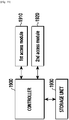
- an apparatus of a terminal in a wireless communication system includes a first communication module configured to support a first system, a second communication module configured to support a second system, and a controller configured to receive information regarding an operation of the second system by using the first communication module and, based on the information regarding the operation of the second system, control an activation state of the second module.
- an apparatus of a base station supporting a first system includes a communication module, and a controller configured to detect a presence/absence of downlink traffic of a second system for a terminal, and transmit information regarding an operation of the second system of the terminal to the terminal via a link of the first system based on the presence/absence of the downlink traffic of the second system.
- an apparatus of a base station supporting a second system includes a communication module, and a controller configured to determine whether first information for indicating a communication module state of a second system controlled by a first system for a terminal is matched to second information for indicating a communication module state of a second system of the terminal, and request, if the first information is not matched to the second information, to change the communication module state of the second system of the terminal.
- a method of controlling a terminal in a wireless communication system includes receiving, from a base station of a first system via a first communication module configured to support the first system, a signal containing information for indicating whether downlink traffic is generated for at least one different terminal, and transmitting, to the at least one terminal, a signal for requesting to control an activation state of a communication module corresponding to the downlink traffic.
- a method of controlling a terminal in a wireless communication system includes receiving from a different terminal a signal for requesting to control an activation state of a second communication module corresponding to a second system via a first communication module corresponding to a first system, and controlling the activation state of the second communication module corresponding to the second system based on the signal received from the different terminal.
- an apparatus of a terminal in a wireless communication system includes a communication unit having a plurality of communication modules supporting different systems, and a controller configured to receive, from a base station of a first system via a first communication module configured to support the first system, a signal containing information for indicating whether downlink traffic is generated for at least one different terminal, and transmit, to the at least one terminal, a signal for requesting to control an activation state of a communication module corresponding to the downlink traffic.
- an apparatus of a terminal in a wireless communication system includes a communication unit having a plurality of communication modules supporting different systems, and a controller configured to receive from a different terminal a signal for requesting to control an activation state of a second communication module corresponding to a second system via a first communication module corresponding to a first system, and control the activation state of the second communication module corresponding to the second system based on the signal received from the different terminal.
- the present disclosure can decrease power consumption of a terminal in a licensed and unlicensed band multi-RAT environment in such a manner that, among a plurality of communication modules supporting different RATs and included in the terminal, an activation state of a 1 st communication module supporting a 1 st RAT is kept, and at least one different communication module is activated only in the presence of traffic through a corresponding system and is deactivated in the absence of traffic.
- the present disclosure also can decrease power consumption in terminals in a group in such a manner that a group of a plurality of terminals is formed and thereafter a representative terminal in the group performs downlink monitoring for different terminals in the group, and controls an activation state of a communication module for different terminals in the group according to a result of the downlink monitoring.
- a mobile station (MS) may be fixed or mobile, and may also be called other terms, such as a user equipment (UE), a mobile terminal (MT), a user terminal (UT), a subscriber station (SS), a wireless device, a personal digital assistant (PDA), a handheld device, and the like.
- UE user equipment
- MT mobile terminal
- UT user terminal
- SS subscriber station
- PDA personal digital assistant
- a base station is generally a fixed station which communicates with the MS, and may also be called other terms, such as an evolved-nodeB (eNB), a base transceiver system (BTS), an access point, and the like.
- eNB evolved-nodeB
- BTS base transceiver system
- access point an access point
- the present disclosure described hereinafter relates to a method and an apparatus for decreasing power consumption of a UE simultaneously supporting a licensed band communication system and an unlicensed band communication system in a licensed and non-licensed band multi-radio access technology (RAT) environment.
- RAT multi-radio access technology
- FIG. 1 illustrates a network system in a licensed band and unlicensed band multi-RAT environment according to an embodiment of the present disclosure.
- a UE 120 may communicate with a macro eNB 100 of the licensed band and small eNBs 111 to 117 of the unlicensed band. Therefore, the UE 120 according to the embodiment of the present disclosure may include a communication module for communicating with the macro eNB 100 of the licensed band and a communication module for communicating with the small eNBs 111 to 117 of the unlicensed band.
- the macro eNB 100 may occupy a channel by using the licensed band, have a wide coverage, use a narrow bandwidth, and provide a low data transfer rate.
- the small eNBs 111 to 117 may occupy a channel by using the unlicensed band, have a narrow coverage, use a wide bandwidth, and provide a high data transfer rate.
- a network structure of a multi-RAT environment for communicating with the UEs 120 and 220 may be the same as shown in FIG. 2A or 2B .
- FIGS. 2A and 2B illustrate a network structure of a multi-RAT environment according to various embodiments of the present disclosure.
- a UE 220 may transmit/receive data and signaling to/ from an eNB 200 and an AP 210.
- the AP 210 according to an embodiment of the present disclosure directly transmits/receives data for the UE 220 to/from a gateway (GW)/home subscriber server (HSS) 240, but may transmit/receive signaling for the UE 220 to/from a mobility management entity (MME) 230 and the GW/HSS 240 via the eNB 200.
- MME mobility management entity
- the AP 210 may transmit/receive data and signaling for the UE 220 to/from the MME 230 and the GW/HSS 240 via the eNB 200.
- the small eNBs 111 to 116 may transmit/receive signaling for the UEs 120 and 220 via the macro eNB 100 (e.g., the eNB 200). Further, the small eNBs 111 to 116 (e.g., the AP 210) according to the embodiment of the present disclosure may transmit/ receive data for the UEs 120 and 220 via the macro eNB 100, or may directly transmit/ receive the data to/from a higher network node.
- the small eNBs 111 to 116 transmit/receive data and signaling via the macro eNB 100 (e.g., the eNB 200) is assumed hereinafter in the embodiment of the present disclosure described.
- the embodiment of the present disclosure described hereinafter may also be applied to a case where the small eNBs 111 to 116 (e.g., the AP 210) transmit/receive signaling via the eNB 100 (e.g., the eNB 200) and directly transmit/receive data to/ from a higher network node. Only a difference occurring when the small eNBs 111 to 116 directly transmit/receive data for the UE to/from the higher network node is described below.
- FIG. 3 illustrates a power saving mode (PSM) mechanism of a WLAN according to an embodiment of the present disclosure.
- PSM power saving mode
- a UE supporting a WLAN of an unlicensed band uses a PSM mechanism to decrease power consumption.
- the PSM mechanism implies a mechanism in which a communication module supporting the WLAN of the UE operates in an awake status in a beacon duration periodically repeated, and if it is identified that there is no downlink traffic through a received beacon, operates in a sleep mode until a next beacon duration.
- an AP 210 of the WLAN periodically transmits a beacon 310, and in this case, a traffic indication map (TIM) included in the beacon indicates a presence/absence of traffic to a UE 220. Therefore, the UE 220 receives the beacon 310 by operating a WLAN communication module in the awake status according to a periodic transmission duration of the beacon 310.
- the UE 220 may operate the WLAN communication module in the sleep state until a next duration of the beacon 310.
- the UE operating according to the PSM mechanism must operate the WLAN communication module in the awake status in every beacon transmission duration periodically repeated even though there is no downlink data, and thus may periodically consume a great amount of power.
- FIG. 4 illustrates a power consumption rate depending on a PSM operation of a UE according to an embodiment of the present disclosure.
- an amount of power consumed in a duration in which the UE operates in the awake status is greater than an amount of power consumed in a sleep duration.
- power consumed in the warming-up time duration is 27.5mW, which is greater by more than 8000 times the power 0.0033mW consumed in the sleep time duration. Therefore, in a situation in which there is no downlink data for the UE, the UE operates in the awake status to periodically receive a beacon, thereby unnecessarily consuming power.
- there is a method of increasing a beacon transmission period which may cause a delay in downlink data transmission to the UE.
- the UE operating according to the PSM mechanisms may not be able to receive downlink data due to a failure in occupying a channel of an AP in an environment in which a plurality of APs are congested.
- FIG. 5 illustrates a situation in which an AP fails to occupy a channel in an environment in which overlapping WLANs are congested according to an embodiment of the present disclosure.
- each AP 210 may not be able to occupy a channel in a pre-set beacon transmission period.
- the AP 210 may transmit a beacon signal at a different time other than a time corresponding to the pre-set beacon transmission period. For example, if the AP 210 succeeds in the channel occupation, a beacon is transmitted at time points a, b, c, d, and e, whereas if the AP 210 fails in the channel occupation, a situation may occur in which the beacon cannot be transmitted at the time point b 500 and thus the beacon is transmitted at a time point b' 501.
- a UE operates in an awake status only in the pre-set beacon transmission period according to the PSM mechanism, and thus cannot receive the beacon transmitted at the time point b' 501. Therefore, even if information for indicating a presence of downlink data for the UE 220 exists in the beacon transmitted at the time point b' 501, the UE 220 cannot recognize this and thus operates in the sleep status.
- an embodiment of the present disclosure describes a method and an apparatus for avoiding a downlink data transmission delay and/or data reception failure situation while minimizing unnecessary power consumption of a UE.
- the embodiment of the present disclosure described hereinafter is for keeping an activation state of some communication modules among a plurality of communication modules supporting different RATs and included in the UE in a licensed and unlicensed band multi-RAT environment, and is for controlling an activation state of the other communication modules.
- a macro cell network of a licensed band is called a 1 st access system
- a small cell network of an unlicensed band is called a 2 nd access system.
- the embodiment described hereinafter may also be equally applied to a case where the 1 st access system is the small cell network of the unlicensed band
- the 2 nd access system is the macro cell network of the licensed band.
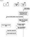
- FIG. 6 illustrates a method of controlling an activation state of a 2 nd access module of a UE supporting a multi-RAT according to an embodiment of the present disclosure.
- a UE 620 includes a 1 st access module supporting a 1 st access system and a 2 nd access module supporting a 2 nd access system.
- the access module may include at least one of a modem, a radio frequency (RF) module, and a power amplifier (PA).
- RF radio frequency
- PA power amplifier
- the UE 620 according to the embodiment of the present disclosure may communicate with a 1 st access eNB 600 while keeping an activation state of a 1 st access module 621. Further, the UE 620 according to the embodiment of the present disclosure may activate or deactivate a 2 nd access module 622 based on information received from the 1 st access eNB 600 while keeping the activation state of the 1 st access module 621. For example, the UE 620 according to the embodiment of the present disclosure detects a presence/absence of traffic to be received via a 2 nd access link, based on information received via a link of the 1 st access system from the 1 st access eNB 600.
- the UE 620 activates the 2 nd access module 622 in the presence of traffic to be received via the 2 nd access link, and deactivates the 2 nd access module 622 in the absence of the traffic to be received via the 2 nd access link.
- an activation state of an access module implies that the access module operates in an awake status (or mode), and a deactivation state of the access module may imply that the access module operates in a sleep status (or mode).
- the 1 st access eNB 600 detects generation of downlink traffic to be transmitted to the UE 620 via a 2 nd access eNB 610.
- the 1 st access eNB 600 may detect the generation of downlink traffic.
- the 1 st access eNB 600 may transmit a signal for instructing activation of the 2 nd access module 622 to the UE 620 via a 1 st access link.
- the UE 620 activates the 2 nd access module 622 in a deactivation state in preparation for receiving a signal from the 2 nd access eNB via the 2 nd access link.
- the 1 st access eNB 600 transmits the detected downlink data to the 2 nd access eNB 610.
- the 2 nd access eNB 610 transmits to the UE 620 the downlink data received from the 1 st access eNB 600 via the 2 nd access link.
- the UE 620 receives the downlink data from the 2 nd access eNB 610 by using the activated 2 nd access module 622.
- the 1 st access eNB 600 may transmit a signal for instructing deactivation of the 2 nd access module 622 to the UE 620 via the 1 st access link.
- the UE 620 may deactivate the 2 nd access module 622, based on the deactivation instruction signal of the 2 nd access module 622 from the 1 st access eNB 600.
- the UE 620 may automatically deactivate the 2 nd access module 622. For example, the UE 620 may deactivate the 2 nd access module 622 by using a timer, instead of receiving the deactivation instruction signal of the 2 nd access module 622 from the 1 st access eNB 600. Information on the timer may be received from the 1 st access eNB 600, or may be stored in the UE 620.
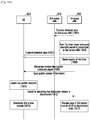
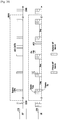
- FIG. 7 illustrates a signal flow for activating a 2 nd access module of a UE according to an embodiment of the present disclosure. It is assumed herein that the 2 nd access module of the UE is in a deactivation state.
- a 1 st access eNB 600 detects downlink traffic to be transmitted to a UE 620 via a 2 nd access eNB 610.
- the 1 st access eNB 600 receives downlink data for a 2 nd access system of the UE 620 from a higher network node.
- the 1 st access eNB 600 identifies that the 2 nd access module of the UE 620 is in the deactivation state.
- the 1 st access eNB 600 may identify that the 2 nd access module is in the deactivation state, based on pre-stored state information for the 2 nd access module of the UE 620.
- the 1 st access eNB 600 transmits a signal for instructing activation of the 2 nd access module to the UE 620 via a 1 st access link.
- the 1 st access eNB 600 may instruct the UE 620 to activate the 2 nd access module by using a radio resource control (RRC) reconfiguration message.
- RRC radio resource control
- the 1 st access eNB 600 may instruct the UE 620 to activate the 2 nd access module by using a media access control (MAC) common emitter (CE) signal for controlling an activation state of a secondary (S) cell.
- MAC media access control
- CE common emitter
- the 1 st access eNB 600 may instruct the UE 620 to activate the 2 nd access module by using a physical downlink control channel (PDCCH).
- PDCH physical downlink control channel
- any one of the RRC reconfiguration message, the MAC CE, and the PDCCH may be selected based on how quickly the 2 nd access module of the UE 620 must be activated.
- the 1 st access eNB 600 stores the state information for the 2 nd access module of the UE 620 by changing its state to an activation state.
- the 1 st access eNB 600 transmits downlink data to the 2 nd access eNB 610.
- an order of performing operations 705, 707, and 709 may be changed depending on a design rule.
- the UE 620 receives the signal for instructing activation of the 2 nd access module via the 1 st access module, and in operation 721, activates the 2 nd access module.
- the 2 nd access eNB 610 receives downlink data from the 1 st access eNB 600, and in operation 711, transmits the downlink data to the UE 620 via the 2 nd access link.
- the UE 620 may receive the downlink data transmitted from the 2 nd access eNB 610 via the 2 nd access module.
- the UE 620 may activate the 2 nd access module, and thereafter may transmit a response signal for the signal for instructing activation of the 2 nd access module to the 1 st access eNB 600.
- the UE 620 may transmit the response signal to the 1 st access eNB 600 via the 1 st access link.
- the UE 620 may transmit the response signal to the 2 nd access eNB 610 via a 2 nd access link. In this case, the 2 nd access eNB 610 may deliver the response signal to the 1 st access eNB 600.
- the 1 st access eNB 600 may transmit the state information for the 2 nd access module of the UE 620 to the 2 nd access eNB 610. For example, whenever the state information for the 2 nd access module of the UE 620 is changed, the 1 st access eNB 600 may transmit the changed state information to the 2 nd access eNB 610. For another example, the 1 st access eNB 600 may periodically transmit the state information for the 2 nd access module of the UE 620.
- FIG. 8A illustrates a signal flow for activating a 2 nd access module of a UE according to an embodiment of the present disclosure.
- FIG. 8D illustrates activation, deactivation, and transmission of a 2 nd access module through 1 st access control transmission, and a time and operation of receiving a beacon signal of a 2 nd access eNB by a UE according to another embodiment of the present disclosure.
- FIG. 8E illustrates a TIM configuration of a typical beacon signal. It is assumed herein that the 2 nd access module of the UE is in a deactivation state according to an embodiment of the present disclosure.
- a 1 st access eNB 600 detects downlink traffic to be transmitted to a UE 620 via a 2 nd access eNB 610.
- the 1 st access eNB 600 receives downlink data for a 2 nd access system of the UE 620 from a higher network node.
- the 1 st access eNB 600 identifies that the 2 nd access module of the UE 620 is in the deactivation state.
- the 1 st access eNB 600 may identify that the 2 nd access module is in the deactivation state, based on pre-stored state information for the 2 nd access module of the UE 620.
- the 1 st access eNB 600 transmits a signal for instructing activation of the 2 nd access module to the UE 620 via a 1 st access link.
- the 1 st access eNB 600 may instruct the UE 620 to activate the 2 nd access module by using an RRC reconfiguration message.
- the 1 st access eNB 600 may instruct the UE 620 to activate the 2 nd access module by using an MAC CE signal for controlling an activation state of an S cell.
- the 1 st access eNB 600 may instruct the UE 620 to activate the 2 nd access module by using a PDCCH.
- the RRC reconfiguration message, the MAC CE, and the PDCCH have different transmission rates or transmission delays, any one of the RRC reconfiguration message, the MAC CE, and the PDCCH may be selected based on how quickly the 2 nd access module of the UE 620 must be activated.
- the 1 st access eNB 600 stores the state information for the 2 nd access module of the UE 620 by changing its state to an activation state.
- the 1 st access eNB 600 instructs the 2 nd access eNB 610 to transmit a short beacon in operation 809, and transmits downlink data to the 2 nd access eNB 610 in operation 811.
- an order of performing operations 805 to 811 may be changed depending on a design rule.
- the UE 620 receives the signal for instructing activation of the 2 nd access module via the 1 st access module, and in operation 821, activates the 2 nd access module.
- the 2 nd access eNB 610 transmits the short beacon in operation 813 according to the short beacon transmission instruction received from the 1 st access eNB 600. Thereafter, in operation 815, the 2 nd access eNB 610 transmits the downlink data to the UE 620 via a 2 nd access link.
- a short beacon 852 is not transmitted at a time of transmitting a periodically repeated beacon 850 but is transmitted at a time point between beacon transmission periods. This is for allowing the UE 620 to receive a 2 nd access module activation signal via the 1 st access module, to activate the 2 nd access module, thereafter to receive the short beacon 852 instead of waiting until a next beacon reception duration, and thereafter to immediately receive downlink data.
- the short beacon may be configured by including only some pieces of information required by the UE 620 to receive downlink data among a plurality of pieces of information included in a well-known beacon signal.
- a configuration for the short beacon will be described below with reference to FIGS. 8F to 8H .
- the UE 620 may receive the downlink data transmitted from the 2 nd access eNB 610 via the 2 nd access module.
- the UE 620 of which the 2 nd access module is activated may acquire additional information required to receive downlink data by receiving the short beacon 852 in operation 813, and thus may receive the downlink data via the 2 nd access module in operation 815 without having to wait until a next beacon transmission time. Therefore, a wake-up delay of the UE 620 can be decreased.
- operations 809 and 811 may be skipped, and the 1 st access eNB 600 may transmit additional information included in the 2 nd access module activation instruction signal to be transmitted to the UE 620.
- the additional information may be information regarding downlink data to be transmitted via the 2 nd access eNB 610.
- the UE 620 may activate the 2 nd access module, and thereafter may transmit a response signal for the signal for instructing activation of the 2 nd access module to the 1 st access eNB 600.
- the UE 620 may transmit the response signal to the 1 st access eNB 600 via the 1 st access link.
- the UE 620 may transmit the response signal to the 2 nd access eNB 610 via the 2 nd access link. In this case, the 2 nd access eNB 610 may deliver the response signal to the 1 st access eNB 600.
- the 1 st access eNB 600 may transmit the state information for the 2 nd access module of the UE 620 to the 2 nd access eNB 610. For example, whenever the state information for the 2 nd access module of the UE 620 is changed, the 1 st access eNB 600 may transmit the changed state information to the 2 nd access eNB 610. For another example, the 1 st access eNB 600 may periodically transmit the state information for the 2 nd access module of the UE 620.
- FIG. 8B illustrates a signal flow for activating a 2 nd access module of a UE according to an embodiment of the present disclosure.
- FIG. 8D illustrates a time of transmitting a beacon signal of a 2 nd access eNB and receiving a beacon signal of a UE according to an embodiment of the present disclosure.
- FIG. 8E illustrates a frame structure of a typical beacon signal according to another embodiment of the present disclosure.
- a UE 620 may activate only a 1 st access module in operation 820.
- a 2 nd access module may be deactivated.
- a 2 nd access eNB 611 and a 2 nd access eNB 612 may transmit a beacon in a beacon transmission period in operation 822.
- the UE 620 cannot receive the beacon signal of the 2 nd access eNB 611 and the 2 nd access eNB 612.
- a 1 st access eNB 600 detects traffic for the 2 nd access system. For example, the 1 st access eNB 600 receives downlink traffic to be transmitted to the 2 nd access eNB 611 or to the UE 620 via the 2 nd access eNB 611 from a higher network node. The 1 st access eNB 600 identifies that the 2 nd access module of the UE 620 is in a deactivation state, and in operation 826, transmits a 2 nd access module activation instruction signal to the UE 620.
- the 1 st access eNB 600 may identify that the 2 nd access module is in the deactivation state.
- the 2 nd access module activation instruction signal may include beacon option information and uplink resource allocation information.
- the beacon option information may indicate a type of a beacon signal transmitted by the 2 nd access eNB 611 or 612. In other words, the beacon option information may indicate whether a short beacon signal is transmitted by the 2 nd access eNB 611 or 612.
- the uplink resource allocation information may indicate information of uplink resources allocated to transmit an activation response signal of the UE 620.
- the activation response signal implies a signal for informing the 1 st access eNB of whether the UE 620 has received the beacon signal of the 2 nd access eNB.
- uplink resources allocation is performed for a beacon reception response.
- the 1 st access eNB 600 transmits downlink data to the 2 nd access eNB 611 to which the UE 620 has access.
- the 2 nd access eNB 611 buffers downlink data received for the UE 620 from the 1 st access eNB 600.
- the UE 620 receives a 2 nd access module activation instruction signal via the 1 st access module, and in operation 828, activates the 2 nd access module. Thereafter, in operation 834, the UE 620 transmits a 2 nd access module activation response signal to the 2 nd access eNB 611 via the 2 nd access module. In operation 836, the UE 620 may drive a short beacon reception (SBR) timer for receiving a short beacon signal. According to a design rule, operations 834 and 836 may be performed simultaneously, or operation 834 may be performed after operation 836 is performed.
- SBR short beacon reception
- the 2 nd access eNB 611 may recognize that the short beacon signal must be transmitted immediately. Thereafter, in operation 840, the 2 nd access eNB 611 may transmit the short beacon signal, and may transmit the buffered downlink data.
- the downlink data may be transmitted together with the short beacon, or may be transmitted immediately after the short beacon is transmitted.
- the short beacon may be configured by including only some pieces of information required by the UE 620 to receive the downlink data among a plurality of TIM information included in the well-known beacon signal. A configuration for the short beacon will be described below with reference to FIGS. 8F to 8H .
- the UE 620 may receive the short beacon signal via the 2 nd access module, and may receive downlink data.
- the UE 620 of which the 2 nd access module is activated may acquire additional information required to receive downlink data by receiving a short beacon, and thus may receive downlink data from the 2 nd access eNB 611 without having to wait until a next beacon transmission time.
- the UE 620 receives the short beacon from the 2 nd access eNB 611, and if the SBR timer expires in operation 842, may transmit an activation response signal to the 1 st access eNB 600 in operation 844.
- the UE 620 may transmit the activation response signal to the 1 st access eNB 600 before the SBR timer expires.
- the UE 620 may determine a 2 nd access module activation time based on the beacon option information included in the 2 nd access module activation instruction signal.
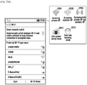
- FIG. 8C illustrates a UE operation and uplink resource allocation based on beacon option information included in a 2 nd access module activation signal according to an embodiment of the present disclosure.
- the UE 620 may activate the 2 nd access module by waiting until a pre-set beacon transmission time, and may receive a beacon based on the method of the related art via the activated 2 nd access module.
- uplink resource allocation information included in the 2 nd access module activation instruction signal may include information regarding a resource after a beacon reception time based on the method of the related art.
- the UE 620 may activate the 2 nd access module immediately after the 2 nd access module activation instruction signal is received, and may receive the short beacon via the activated 2 nd access module.
- the uplink resource allocation information included in the 2 nd access module activation instruction signal may include information regarding the resource after the short beacon reception time.
- FIG. 8F illustrates a frame structure of a short beacon signal according to an embodiment of the present disclosure.
- FIG. 8G illustrates information included in a short beacon signal according to an embodiment of the present disclosure.
- FIG. 8H illustrates information included in a short beacon signal based on a frame structure of a short beacon signal according to an embodiment of the present disclosure.
- the frame structure of the short beacon signal may include at least one of a short training field, a field for channel estimation, a header, and data.
- a short training field For example, it may be effective to configure the short beacon signal with a size less than 88 bits, i.e., a size of a control physical header.
- the short beacon signal may be configured by using the following three methods.
- the short beacon signal may include only a short training field.
- the short beacon signal may be configured with a minimum length of 3.636us, and the short beacon signal does not include additional information.
- the short beacon signal may include a short training field, a field for channel estimation, and a header.
- the header of the short beacon signal may include beamforming related information and a partial physical cell identifier (PCID).
- PCID physical cell identifier
- the header of the short beacon signal may include direction information, beam identifier information, antenna identifier information, and partial PCID information.
- the direction information may include uplink and downlink transmission recognition information and information for recognizing a compressed beacon and a best beam feedback
- the beam identifier information may include transmission beam ID information of an AP.
- the antenna identifier information may include antenna ID information
- the partial PCID may include a sequence of the short training field.
- the short beacon signal may include only one header, or may include two headers.
- the direction information, the beam identifier information, the antenna identifier information, and the partial PCID information may consist of 14 bits in total.
- a control physical layer header may include 88-bit information, and in this case, the existing physical layer header consists of 40 bits, and the remaining 48 bits are reserved bits. Therefore, among the 48-bit reserved bits according to the embodiment of the present disclosure, 14-bit information can be additionally used. If the short beacon signal includes one header, a length of the short beacon signal is 8.93us, and may be 88 bits in total. On the other hand, if the short beacon signal includes two headers, the length of the short beacon signal is 13.69us, and may be 176 bits in total.
- the short beacon signal may include a short training field, a field for channel estimation, a header, and data.
- the header of the short beacon field may include information as shown in FIG. 8G .
- the data may include only a 14-byte MAC header, or may include a 14-byte MAC header and 10-byte data, or may include a 14-byte MAC header and 86-byte data.
- FIG. 8I illustrates beam training using a short beacon signal according to an embodiment of the present disclosure.
- the short beacon signal when the beam training is performed using the short beacon signal, the short beacon signal may be transmitted/received repetitively by the number of transmit antenna beams of an AP and the number of receive antenna beams of a UE. Since the short beacon signal may be configured to be significantly shorter than a legacy beacon signal, not only a beam training time can be decreased but also an overhead caused by the beam training can be decreased.
- FIG. 9 illustrates a signal flow for a case where an eNB for a 2 nd access module of a UE is changed according to an embodiment of the present disclosure.
- a UE 620 fails to receive a short beacon signal from a 2 nd access eNB 611 before an SBR timer expires in the aforementioned situation of FIG. 8B . Further, it is assumed in FIG. 9 that the UE 620 detects a situation in which signal reception from the 2 nd access eNB 611 is impossible during downlink data is received from the 2 nd access eNB 611. For example, it is assumed that the situation in which the signal reception from the 2 nd access eNB 611 is impossible is detected due to a movement of the UE 620 or a change in a channel state with respect to the 2 nd access eNB 611.
- a 1 st access module for transmitting/receiving a signal to/from a 1 st access eNB 600 may be persistently kept in an activation state.
- the UE 620 may transmit an activation response signal to the 1 st access eNB 600.
- the activation response signal may include information for indicating whether an eNB change is necessary and short beacon request information.
- the UE 620 may deactivate the 2 nd access module if the SBR timer expires in a state where the short beacon signal is not received. Further, irrespective of the SBR timer, the UE 620 may deactivate the 2 nd access module by using an additional timer for determining a time of deactivating the 2 nd access module at a time when the 2 nd access module is activated.
- the UE 620 may deactivate the 2 nd access module if the additional timer expires in a state where downlink signal is not detected via the 2 nd access module.
- the 1 st access eNB 600 transmits a short beacon request signal to the 2 nd access eNB 611 and a 2 nd access eNB 612.
- the short beacon request signal may be transmitted to the 2 nd access eNB 611 and/or at least one 2 nd access eNB neighboring to the 2 nd access eNB 611.
- the 1 st access eNB 600 may select at least one 2 nd access eNB for transmitting the short beacon request signal, based on a pre-registered 2 nd access eNB list.
- the 2 nd access eNB list may include location information of each 2 nd access eNB and/or information of a 2 nd access eNB neighboring to each 2 nd access eNB. Further, the 1 st access eNB 600 may select at least one 2 nd access eNB for transmitting the short beacon request signal, based on a location of the UE 620.
- the 1 st access eNB 600 retransmits an uplink resource allocation signal for transmitting an activation response signal of the UE 620.
- the UE 620 may activate the 2 nd access module.
- the 2 nd access eNB 611 and the 2 nd access eNB 612 transmit the short beacon signal.
- the 2 nd access eNB 611 and the 2 nd access eNB 612 may transmit the short beacon signal immediately after the short beacon request signal is received, or may transmit the short beacon signal based on a short beacon signal transmission time included in the short beacon request signal. If the 2 nd access eNB 611 or the 2 nd access eNB 612 does not support short beacon signal transmission, a corresponding 2 nd access eNB may transmit a legacy beacon signal at a pre-set beacon signal transmission time.
- the UE 620 receives a short beacon (and/or a beacon signal) via the 2 nd access module.
- a short beacon and/or a beacon signal
- the UE 620 fails to receive the short beacon signal from the 2 nd access eNB 611 and receives the beacon signal from the 2 nd access eNB 612.
- the UE 620 receives the short beacon signal from the 2 nd access eNB 611 and the 2 nd access eNB 612, but reception strength of the short beacon signal from the 2 nd access eNB 611 is less than a threshold and reception strength of the short beacon signal from the 2 nd access eNB 612 is greater than or equal to the threshold.
- the UE 620 determines a handover to the 2 nd access eNB 612, based on a result of receiving the short beacon signal.
- the UE 620 transmits an activation response signal to the 1 st access eNB 600.
- the activation response signal may include information for indicating that an AP change is necessary and identification information for a target AP.
- the UE 620 may deactivate the 2 nd access module.
- the 1 st access eNB 600 identifies the target 2 nd access eNB 611 to which the UE 620 intends to be handed over from the activation response signal received from the UE 620, and in operation 922, transmits an add request signal to the 2 nd access eNB 612.
- the add request signal may include information regarding the UE 620.
- the 2 nd access eNB 612 transmits an add request acknowledgment (ACK) signal to the 1 st access eNB 600.
- ACK add request acknowledgment
- the 2 nd access eNB 612 may transmit the add request ACK signal by considering a load depending on the number of UEs currently having access thereto.
- the 1 st access eNB 600 and the 2 nd access eNB 612 configure a data path for the UE 620.
- the 1 st access eNB 600 transmits a radio resource control connection reconfiguration signal to the UE 620.
- the UE 620 transmits a radio resource control connection reconfiguration complete signal to the 1 st access eNB 600.
- information e.g., packet data convergence protocol (PDCP) sequence number (SN)
- PDCP packet data convergence protocol
- SN sequence number
- the 1 st access eNB 600 Upon receiving the radio resource control connection reconfiguration complete signal, in operation 932, the 1 st access eNB 600 transmits downlink data for the UE 620 to the 2 nd access eNB 612. Upon receiving the PDCP SN for the last downlink data from the UE 620, the 1 st access eNB 600 may deliver downlink data subsequent to the PDCP SN to the 2 nd access eNB 612.
- the UE 620 may activate the 2 nd access module, and in operation 934, may transmit to the 2 nd access eNB 612 a 2 nd access module activation response signal for indicating that the 2 nd access module is activated. According to a design rule, after activating the 2 nd access module, the UE 620 may not transmit the 2 nd access module activation response signal.
- the UE 620 may receive downlink data from the 2 nd access eNB 612.
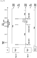
- FIG. 10A illustrates a signal flow for deactivating a 2 nd access module of a UE based on control transmission of a 1 st access eNB according to an embodiment of the present disclosure. It is assumed herein that the 2 nd access module of the UE is in an activation state.
- a 1 st access eNB 600 transmits downlink data for a UE 620 to a 2 nd access eNB 610.
- the 1 st access eNB 600 may recognize that a 2 nd access module of the UE 620 is in an activation state, and may transmit the downlink data for the UE 620 to the 2 nd access eNB 610.
- the 1 st access eNB 600 measures a pre-set time by starting a 1 st timer at a time when downlink data is transmitted. If downlink data to be transmitted to the UE 620 via the 2 nd access eNB 610 is additionally detected before the 1 st timer expires or before a pre-set time elapses, returning to operation 1001, the 1 st access eNB 600 transmits downlink data for the UE 620 to the 2 nd access eNB 610. In this case, the 1 st timer is reset at a time when the additionally detected downlink data is transmitted, and thus the pre-set time is measured again.
- a set time of the 1 st timer may be determined according to a type of a 2 nd access module activation signal.
- the set time of the 1 st timer may be determined by considering which one is used to transmit a 2 nd access module activation instruction among an RRC reconfiguration message, an MAC CE, and a PDCCH.
- the 2 nd access eNB 610 transmits to the UE 620 the downlink data received from the 1 st access eNB 600.
- the 1 st access eNB 600 may detect an expiry of the 1 st timer. If the 1 st timer expires since additional downlink data is not detected within a pre-set time from the time when the downlink data for the UE 620 is transmitted to the 2 nd access eNB 160, the 1 st access eNB 600 may determine that last downlink data is transmitted.
- the 1 st access eNB 600 transmits a signal for instructing deactivation of the 2 nd access module to the UE 620 via a 1 st access link.
- the signal for instructing deactivation of the 2 nd access module may include a sequence number for a last downlink packet transmitted by the 1 st access eNB 600 to the 2 nd access eNB 610.
- the signal for instructing deactivation of the 2 nd access module may include a PDCP SN of the last downlink packet for the UE 620.
- the signal for instructing deactivation of the 2 nd access module may include a PDCP SN of a last downlink packet to be received by the UE 620.
- the 1 st access eNB 600 may instruct deactivation of the 2 nd access module by using a probe request signal.
- the UE 620 may receive the signal for instructing deactivation of the 2 nd access module via the 1 st access link, and in operation 1011, may acquire a sequence number for a last packet from the 2 nd access module deactivation instruction signal.
- the UE 620 may detect that the last packet is received based on the sequence number for the last packet acquired in operation 1011. For example, based on the sequence number acquired from the 2 nd access eNB 610, the UE 620 may determine that all plackets are received including up to the last downlink data packet. According to the embodiment of the present disclosure, if the sequence number for the last packet is not included in the 2 nd access module deactivation instruction signal, operation 1011 may be skipped.
- the UE 620 may acquire a PDCP SN of the last downlink packet from the signal for instructing deactivation of the 2 nd access module, and may determine that all packets are received including up to the last downlink data packet based on the acquired PDCP SN.
- the UE 620 transmits to the 1 st access eNB 600 a signal for indicating that the 2 nd access module is deactivated in operation 1013, and deactivate the 2 nd access module in operation 1015.
- the UE 620 may indicate that the 2 nd access module is deactivated by using a probe request signal.
- the UE 620 may indicate that the 2 nd access module is deactivated by using a PDCP feedback signal for indicating a sequence number of a received last packet.
- the UE 620 may not transmit the signal for indicating that the 2 nd access module is deactivated.
- the 1 st access eNB 600 Upon receiving the signal for indicating that the 2 nd access module is deactivated, in operation 1017, the 1 st access eNB 600 stores the state information for the 2 nd access module of the UE 620 by changing its state to a deactivation state.
- the signal for indicating that the 2 nd access module is deactivated may not be received from the UE 620.
- the 1 st access eNB 600 may determine whether the UE 620 receives a last packet based on an automatic repeat request (ARQ) response signal for a downlink data packet received from the UE 620, and may store the state information for the 2 nd access module of the UE 620 by changing its state to the deactivation state.
- the ARQ response signal may be received directly from the UE 620 via the 1 st access link or may be received via the 2 nd access eNB 610.
- the UE 620 when the UE 620 deactivates the 2 nd access module, it implies that the 2 nd access module is changed to a sleep mode and is kept persistently in the sleep mode. For example, when the 2 nd access module is in the deactivation state, the UE 620 does not perform an operation of monitoring a presence of downlink traffic for the 2 nd access link until the 2 nd access module activation instruction signal is received.
- the UE 620 may perform any one of the following operations 1 to 3 to deactivate the 2 nd access module.
- the UE 620 determines whether to receive the last downlink packet reception based on the PDCP SN, and transmits the signal for indicating that the 2 nd access module is deactivated by including the PDCP SN of the last downlink packet received by the UE 620.
- the UE 620 and the 1 st access eNB 600 may operate based on any one scenario among four types of scenarios as shown in FIG. 10B according to various embodiments of the present disclosure. For example, it is described under the assumption that the 2 nd access module deactivation instruction signal is a WLAN sleep request signal, and the signal for indicating that 2 nd access module is deactivated is a WLAN sleep response signal.
- the 1 st access eNB 600 transmits to the UE 620 a WLAN sleep request signal not including PDCP SN information of the last downlink packet to be received by the UE 620.
- the UE 620 does not know information regarding the last downlink packet, and thus may deactivate the 2 nd access module immediately after the WLAN sleep request signal is received. Thereafter, the UE 620 transmits a WLAN sleep response signal to the 1 st access eNB 600. In this case, the WLAN sleep response signal does not include the PDCP SN information of the last downlink packet.
- the 1 st access eNB 600 and the UE 620 cannot recognize a difference between the PDCP SN of the last downlink packet to be received by the UE 620 and a PDCP SN of a last downlink packet actually received by the UE 620, which may result in a packet loss.
- the 1 st access eNB 600 transmits to the UE 620 the WLAN sleep request signal not including the PDCP SN information of the last downlink packet to be received by the UE 620.
- the UE 620 does not know information regarding the last downlink packet, and thus may deactivate the 2 nd access module immediately after the WLAN sleep request signal is received. Thereafter, the UE 620 transmits a WLAN sleep response signal to the 1 st access eNB 600.
- the WLAN sleep response signal may include the PDCP SN information of the downlink packet last received by the UE 620.
- the 1 st access eNB 600 may recognize the difference between the PDCP SN of the last downlink packet to be received by the UE 620 and a PDCP SN of a last downlink packet actually received by the UE 620. If it is determined that the UE 620 has failed to receive up to the last downlink packet as a result of comparing the PDCP SN of the last downlink packet to be received by the UE 620 and the PDCP SN of the last downlink packet actually received by the UE 620, the 1 st access eNB 600 may transmit downlink packets, which are not received by the UE 620, to the UE 620 via the 1 st access link. Therefore, the UE 620 may receive downlink data, which has a PDCP SN greater than the PDCP SN transmitted to the 1 st access eNB, via the 1 st access link.
- the 1 st access eNB 600 transmits to the UE 620 the WLAN sleep request signal including the PDCP SN information of the last downlink packet to be received by the UE 620. Therefore, the UE 620 can know information regarding the last downlink packet, and thus keeps an activation state of the 2 nd access module until the last downlink packet is received, and deactivates the 2 nd access module when the last downlink packet is received. Thereafter, the UE 620 may not transmit a response signal to the 1 st access eNB 600.
- the UE 620 may recognize a difference between a PDCP SN of a last downlink packet to be received and a PDCP SN of a received downlink packet. Thereafter, the UE 620 may receive up to the last downlink packet based on the PDCP SN included in the WLAN sleep request signal, and may deactivate the 2 nd access module after detecting that up to the last downlink packet is received.
- the 1 st access eNB 600 transmits to the UE 620 the WLAN sleep request signal including the PDCP SN information of the last downlink packet to be received by the UE 620. Therefore, the UE 620 may know information regarding the last downlink packet. In this case, the UE 620 may deactivate the 2 nd access module after receiving all packets including up to the last downlink packet, and may transmit to the 1 st access eNB 600 a WLAN sleep response signal including the PDCP SN information of the downlink packet last received by the UE 620.
- the UE 620 may deactivate the 2 nd access module immediately when the WLAN sleep request signal is received, and may transmit to the 1 st access eNB 600 the WLAN sleep response signal including the PDCP SN information of the downlink packet last received by the UE 620. Therefore, the 1 st access eNB 600 and the UE 620 may recognize the difference between the PDCP SN of the last downlink packet to be received by the UE 620 and a PDCP SN of a last downlink packet actually received by the UE 620.
- the 1 st access eNB 600 may transmit downlink packets, which are not received by the UE 620, to the UE 620 via the 1 st access link.
- FIG. 11A illustrates a signal flow for deactivating a 2 nd access module autonomously by a UE based on initial deactivation timer information of the UE according to an embodiment of the present disclosure. It is assumed herein that the 2 nd access module is in an activation state.
- a 1 st access eNB 600 may transmit an RRC configuration message including deactivation timer information in an initial setup process for an RRC connection with a UE 620.
- the deactivation timer information includes time information used to determine whether the 2 nd access module is deactivated.
- the deactivation timer information may be determined according to a type of a 2 nd access module activation signal transmitted by the 1 st access eNB to the UE 620. For example, time information of a deactivation timer may be determined by considering which one is used to transmit a 2 nd access module activation instruction among an RRC reconfiguration message, an MAC CE, and a PDCCH.
- the 1 st access eNB 600 transmits downlink data for the UE 620 to a 2 nd access eNB 610.
- the 1 st access eNB 600 may recognize that the 2 nd access module of the UE 620 is in an activation state, and may transmit the downlink data for the UE 620 to the 2 nd access eNB 610.
- the 1 st access eNB 600 measures a pre-set time by starting a 1 st timer at a time when downlink data is transmitted. If downlink data to be transmitted to the UE 620 via the 2 nd access eNB 610 is additionally detected before the 1 st timer expires or before a pre-set time elapses, returning to operation 1103, the 1 st access eNB 600 transmits downlink data for the UE 620 to the 2 nd access eNB 610. In this case, the 1 st timer is reset at a time when the additionally detected downlink data is transmitted, and thus the pre-set time is measured again.
- the set time of the 1 st time may be determined based on deactivation timer information transmitted to the UE 620 in operation 1101. According to the embodiment of the present disclosure, the set time of the 1 st timer may be equal to or different from time information of the deactivation timer.
- the 1 st access eNB 600 may detect an expiry of the 1 st timer. If the 1 st timer expires since additional downlink data is not detected within a pre-set time from the time when the downlink data for the UE 620 is transmitted to the 2 nd access eNB 160, the 1 st access eNB 600 may determine that last downlink data is transmitted. In operation 1109, the 1 st access eNB 600 stores the state information for the 2 nd access module by changing its state to a deactivation state.
- the 2 nd access eNB 610 transmits to the UE 620 the downlink data received from the 1 st access eNB 600.
- the UE 620 receives downlink data from the 2 nd access eNB 610 in operation 1111, and starts a 2 nd timer at a time when downlink data is received in operation 1113, thereby measuring a pre-set time.
- the 2 nd timer may be set based on deactivation timer information included in an RRC configuration message. According to the embodiment of the present disclosure, the set time of the 2 nd timer may be equal to or different from the time information of the deactivation timer.
- the set time of the 2 nd timer may be equal to or different from the set time of the 1 st timer operated by the 1 st access eNB 600.
- the set time of the 2 nd timer may be set by considering a delivery delay between the 1 st access eNB 600 and the 2 nd access eNB 610 and/or a delivery delay between the 2 nd access eNB 610 and the UE 620.
- the UE 620 may detect an expiry of the 2 nd timer. The UE 620 may determine that last downlink data is received if the 2 nd timer expires since additional data downlink is not detected within a pre-set time from a time of receiving downlink data via the 2 nd access link by using the 2 nd access module. In operation 1117, the UE 620 stores the state information for the 2 nd access module by changing its state to a deactivation state.
- the 1 st access eNB 600 transmits deactivation timer information to the UE 620 during an initial connection establishment of the UE 620 and the 1 st access eNB 600, and thus a deactivation state change time for the 2 nd access module of the UE 620 is determined by each of the 1 st access eNB 600 and the UE 620 based on the deactivation timer information.
- the 1 st access eNB 600 may not transmit the deactivation timer information to the UE 600, but the UE 620 may transmit timer information which is pre-set in the UE 620 to the 1 st access eNB 600.
- each of the 1 st access eNB 600 and the UE 620 may determine the deactivation state change time for the 2 nd access module of the UE 620.
- the 1 st access eNB 600 and the UE 620 may not exchange timer information for deactivation of the 2 nd access module, but may determine the deactivation state change time for the 2 nd access module of the UE 620 based on timer information which is pre-set in each of the 1 st access eNB 600 and the UE 620.
- the UE 620 when the UE 620 deactivates the 2 nd access module, it implies that the 2 nd access module is changed to a sleep mode and is kept persistently in the sleep mode. For example, when the 2 nd access module is in the deactivation state, the UE 620 does not perform an operation of monitoring a presence of downlink traffic for the 2 nd access link until the 2 nd access module activation instruction signal is received. According to the embodiment of the present disclosure, the UE 620 may perform any one of the aforementioned operations 1 to 3 to deactivate the 2 nd access module.
- state information of the 2 nd access module managed by the 1 st access eNB 600 may be not matched to a state of the 2 nd access module of the UE 620.
- state information of the 2 nd access module recognized by the 1 st access eNB 600 may be not matched to an actual state of the 2 nd access module of the UE 620 due to a clock draft in each entity, a control signal transmission delay in each entity, and the like.
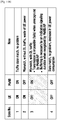
- FIG. 11B illustrates a situation in which a state for a 2 nd access module of a UE is determined in the UE and a 1 st access eNB according to an embodiment of the present disclosure.
- state information of a 2 nd access module managed by a 1 st access eNB 600 and a state of a 2 nd access module of a UE 620 are shown in FIG. 11B .
- 'ON' indicates an activation state of the 2 nd access module
- 'OFF' indicates an inactivate state of the 2 nd access module.
- the UE 620 may transmit/ receive data without any problem.
- the state information of the 2 nd access module of the UE 620 is mismatched, but the UE 620 may receive downlink data without any problem. For example, upon detecting downlink data in a state where the state information of the 2 nd access module is 'OFF', since the 1 st access eNB 600 transmits a signal for changing the 2 nd access module to an activation state and transmits downlink data via the 2 nd access eNB 610, the downlink data can be transmitted without any problem.
- the state information of the 2 nd access module managed by the 1 st access eNB 600 is 'OFF', it implies a situation in which downlink data for the HE 620 is not generated. Therefore, since the 2 nd access module of the UE 620 operates in the activation state in the situation in which the downlink data for the UE 620 is not generated, power of the UE 620 may be wasted.
- the UE 620 may be unable to receive downlink data due to a mismatch of the state information of the 2 nd access module. For example, upon detecting downlink data in a state where the state information of the 2 nd access module is 'ON', the 1 st access eNB 600 does not transmit a signal for changing the 2 nd access module of the UE 620 to the activation state but transmits downlink data via the 2 nd access eNB 610. However, in this case, since the state of the 2 nd access module of the UE 620 is 'OFF', the UE 620 is unable to receive downlink data transmitted from the 2 nd access eNB 610 via the 2 nd access link.
- the state of the 2 nd access module of the UE 620 is 'OFF' and the state information of the 2 nd access module managed by the 1 st access eNB 600 is 'OFF', it implies a state where there is no downlink data for the UE 620.
- the UE 620 may decrease unnecessary power consumption by deactivating the 2 nd access module in a situation in which the downlink data does not exist.
- the 2 nd access eNB 610 may detect a situation in which the state information of the 2 nd access module is mismatched and then may match the state information of the 2 nd access module.
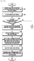
- FIG. 12A illustrates a signal flow for controlling a state of a 2 nd access module by a 2 nd access eNB based on a timer mismatch of a UE and a 1 st access eNB according to an embodiment of the present disclosure. It is assumed herein that the 2 nd access module of the UE is in an activation state.
- a 1 st access eNB 600 transmits downlink data for a UE 620 to a 2 nd access eNB 610.
- the 1 st access eNB 600 may recognize that a 2 nd access module of the UE 620 is in an activation state, and may transmit the downlink data for the UE 620 to the 2 nd access eNB 610.
- the 1 st access eNB 600 measures a pre-set time by starting a 1 st timer at a time when downlink data is transmitted. If downlink data to be transmitted to the UE 620 via the 2 nd access eNB 610 is additionally detected before the 1 st timer expires or before a pre-set time elapses, returning to operation 1201, the 1 st access eNB 600 transmits downlink data for the UE 620 to the 2 nd access eNB 610. In this case, the 1 st timer is reset at a time when the additionally detected downlink data is transmitted, and thus the pre-set time is measured again.
- the 2 nd access eNB 610 starts a network timer in operation 1211 to measure a pre-set time.
- the network timer may be set based on deactivation timer information received in advance from the 1 st access eNB 600.
- the deactivation timer information may include information for a set time of the 1 st timer of the 1 st access eNB.
- the network timer may be set based on information pre-stored in the 2 nd access eNB.
- the set time of the network timer may be equal to or different from the set time of the 1 st timer.
- the set time of the network timer may be set by considering a delivery delay between the 1 st access eNB 600 and the 2 nd access eNB 610. If downlink data for the UE 620 is additionally received from the 1 st access eNB 600 before the network timer expires, the 2 nd access eNB 610 measures again the pre-set time by resetting the network timer.
- the 2 nd access eNB 610 transmits the downlink data to the UE 620 via the 2 nd access link.
- the 2 nd access eNB 610 measures a pre-set time by starting the 1 st timer at a time when downlink data is transmitted.
- a UE timer may be set based on deactivation timer information previously received from the 1 st access eNB 600.
- the deactivation timer information may include information regarding the set time of the 1 st timer of the 1 st access eNB.
- the UE timer may be set based on information pre-stored in the 2 nd access eNB.
- the set time of the UE timer may be equal to or different from the set time of the 1 st timer and/or the set time of the network timer.
- the set time of the UE timer may be set by considering a delivery delay between the 1 st access eNB 600 and the 2 nd access eNB 610 and/or a delivery delay between the 2 nd access eNB 610 and the UE 620. If downlink data for the UE 620 is additionally received from the 1 st access eNB 600 before the UE timer expires, and if the additionally received downlink data is additionally transmitted to the UE 602, the 2 nd access eNB 610 measures again the pre-set time by resetting the UE timer.
- the UE 620 measures the pre-set time by starting a 2 nd timer in operation 1214.
- the 2 nd timer may be set based on the deactivation timer information previously received from the 1 st access eNB 600.
- the set time of the 2 nd timer may be equal to or different from the time information of the deactivation timer.
- the set time of the 2 nd timer may be equal to or different from the set time of the 1 st timer operated by the 1 st access eNB 600.
- the set time of the 2 nd timer may be equal to or different from the set time of the UE timer operated by the 2 nd access eNB 610.
- the set time of the 2 nd timer may be set by considering a delivery delay between the 1 st access eNB 600 and the 2 nd access eNB 610 and/or a delivery delay between the 2 nd access eNB 610 and the UE 620. If downlink data is additionally received from the 2 nd access module via the 2 nd access link before the 2 nd timer expires, the UE 620 measures again the pre-set time by resetting the 2 nd timer.
- the 2 nd access eNB 610 may monitor a state of the UE timer and the network timer to detect a mismatch occurrence. For example, if the network timer is in a running state (e.g., an ON state) and the UE timer is in an expiry state (e.g., an OFF state), the 2 nd access eNB 610 may detect that the mismatch occurs due to the timer. In this case, the 2 nd access eNB 610 may recognize that a state of the 2 nd access module of the UE 620 is a deactivation state and that state information of the 2 nd access module managed by the 1 st access eNB 600 indicates an activation state.
- a state of the 2 nd access module of the UE 620 is a deactivation state
- state information of the 2 nd access module managed by the 1 st access eNB 600 indicates an activation state.
- the 2 nd access eNB may detect that the mismatch occurs due to the timer.
- the 2 nd access eNB 610 may recognize that the state of the 2 nd access module of the UE 620 is the activation state, and the state information of the 2 nd access module managed by the 1 st access eNB 600 indicates a deactivation state.
- the 2 nd access eNB 610 transmits to the 1 st access eNB 600 a signal for requesting to control a state of the 2 nd access module of the UE 620.
- the 2 nd access eNB 610 may transmit the signal for requesting to control the state of the 2 nd access module based on the state information of the 1 st access eNB 600.
- the 2 nd access eNB 610 may transmit a signal for requesting to change the state of the 2 nd access module of the UE 620 from the deactivation state to the activation state.
- the 2 nd access eNB 610 may transmit the signal for requesting to change the state of the 2 nd access module of the UE 620 from the activation state to the deactivation state.
- the 2 nd access eNB 610 may transmit only information indicating that the state of the 2 nd access module of the UE 620 is the activation state.
- the 2 nd access eNB 610 may transmit only information indicating that the state of the 2 nd access module of the UE 620 is different from the state information of the 2 nd access module managed by the 1 st access eNB 600.
- the 1 st access eNB 600 transmits a signal for instructing a state change of the 2 nd access module of the UE 620.
- the signal for instructing the state change of the 2 nd access module may be a signal for instructing activation of the 2 nd access module or a signal for instructing deactivation of the 2 nd access module.
- the signal for instructing the state change of the 2 nd access module may be transmitted by using any one of an RRC reconfiguration message, an MAC CE, and a PDCCH.
- the UE 620 may receive the signal for instructing the state change of the 2 nd access module from the 1 st access eNB 600, and may change the state of the 2 nd access module based on the received signal. Although not shown, the UE 620 may transmit a signal for indicating that the state of the 2 nd access module is changed to the 1 st access eNB 600 via the 1 st access link, or may transmit it to the 2 nd access eNB 610 via the 2 nd access link.
- the 2 nd access eNB 610 may buffer downlink data from the 1 st access eNB 600 instead of transmitting it to the UE 620.
- the 2 nd access eNB 610 may start transmission of the buffered downlink data.
- the 2 nd access eNB 610 may start transmission of the buffered downlink data.
- the 2 nd access eNB 610 requests the 1 st access eNB 600 to change the state of the 2 nd access module of the UE 620.
- the 2 nd access eNB 610 may transmit a signal for requesting to change the state of the 2 nd access module from the activation state to the deactivation state to the UE 620 via the 2 nd access link.
- FIG. 12B illustrates a signal flow for controlling a state of a 2 nd access module of a UE according to an embodiment of the present disclosure.
- FIG. 12B Various embodiments for controlling a state of a 2 nd access module are shown in FIG. 12B when a state mismatch occurs in the 2 nd access module of the UE. More particularly, as shown in FIG. 11B , if a state of the 2 nd access module of a UE 620 is 'OFF' and state information of a 2 nd access module managed by a 1 st access eNB 600 is 'ON' among various states, a situation may occur in which the UE 620 is unable to receive downlink data due to a mismatch of the state information of the 2 nd access module. Therefore, various embodiments for a method for addressing this issue are described.
- a 2 nd access eNB 610 may detect whether a state mismatch occurs in the 2 nd access module for the UE 620. For example, the 2 nd access eNB 610 may detect that the 2 nd access module of the UE 620 is in a deactivation state or the 2 nd access module of the UE 620 managed by the 1 st access eNB 600 is in an activation state. This may be detected by managing the timers described with reference to FIG. 12A .
- the 2 nd access eNB 610 may transmit a signal for instructing deactivation of the 2 nd access module to the 1 st access eNB 600. Accordingly, the 1 st access eNB 600 may recognize that the 2 nd access module of the UE 620 is in the deactivation state, and may manage the state information of the 2 nd access module of the UE 620 as the deactivation state.
- the UE 620 may transmit to the 1 st access eNB 600 a signal for indicating that the state of the 2 nd access module is the deactivation state.
- the UE 620 cannot recognize that the occurrence of the state mismatch of the 2 nd access module for the UE 620 is detected by the 2 nd access eNB 610.
- the UE 620 must periodically transmit to the 1 st access eNB 600 the signal for indicating that the state of the 2 nd access module is the deactivation state, or must transmit to the 1 st access eNB 600 the signal for indicating that the state of the 2 nd access module is the deactivation state whenever the state of the 2 nd access module is deactivated. Accordingly, the 1 st access eNB 600 may recognize that the 2 nd access module of the UE 620 is in the deactivation state, and may manage the state information of the 2 nd access module of the UE 620 as the deactivation state.
- the 1 st access eNB 600 may detect a presence of downlink data for the UE 620 via the 2 nd access eNB 610. In this case, the 1 st access eNB 600 may transmit a signal for requesting to activate the 2 nd access module to the UE 620 in operation 1236.
- the signal for requesting to activate the 2 nd access module may include beacon option information for indicating whether a short beacon is transmitted and uplink resource allocation information for transmission of an activation response signal.
- the 2 nd access module of the UE 620 is activated in operation 1238, and 2 nd access module state information of the UE 620, which is stored in the 1 st access eNB 600 and the 2 nd access eNB 610, may be matched as an activation state in operations 1242 and 1240, respectively.
- a latency may occur to some extents due to an X2 interface between the 2 nd access eNB 610 and the 1 st access eNB.
- this method has an advantage in that a system load is small since the 2 nd access eNB 610 transmits the signal for controlling the state mismatch to the 1 st access eNB only when the state mismatch occurs.
- the 2 nd access eNB 610 may not transmit downlink data but buffer it until the state of the 2 nd access module of the UE 620 is matched to the state information of the 2 nd access module managed by the 1 st access eNB 600.
- the 1 st access eNB 600 transmits a signal for instructing activation of the 2 nd access module to the UE 620 to activate the 2 nd access module
- a transmission delay may occur in the signal for instructing activation of the 2 nd access module.
- the state information of the 2 nd access module managed by the 1 st access eNB 600 is an activation state
- the 2 nd access module of the UE 620 may be actually in a deactivation state.
- the 2 nd access eNB 610 may transmit downlink data to the UE 620 after buffering the downlink data for a specific period of time based on an expected time at which the 2 nd access module is activated.
- the 2 nd access eNB 610 may explicitly transmit a signal for prohibiting deactivation of the 2 nd access module to the UE 620.
- FIG. 12C illustrates a signal flow for prohibiting deactivation of a UE by a 2 nd access eNB according to an embodiment of the present disclosure.
- a 1 st access eNB 600 transmits downlink data for a UE 620 to a 2 nd access eNB 610.
- the 1 st access eNB 600 may recognize that a 2 nd access module of the UE 620 is in an activation state, and may transmit the downlink data for the UE 620 to the 2 nd access eNB 610.
- the 1 st access eNB 600 measures a pre-set time by starting a 1 st timer at a time when downlink data is transmitted. If downlink data to be transmitted to the UE 620 via the 2 nd access eNB 610 is additionally detected before the 1 st timer expires or before a pre-set time elapses, returning to operation 1251, the 1 st access eNB 600 transmits downlink data for the UE 620 to the 2 nd access eNB 610. In this case, the 1 st timer is reset at a time when the additionally detected downlink data is transmitted, and thus the pre-set time is measured again.
- the 2 nd access eNB 610 starts a network timer in operation 1255 to measure a pre-set time.
- the network timer may be set based on deactivation timer information received in advance from the 1 st access eNB 600.
- the deactivation timer information may include information for a set time of the 1 st timer of the 1 st access eNB.
- the network timer may be set based on information pre-stored in the 2 nd access eNB.
- the set time of the network timer may be equal to or different from the set time of the 1 st timer.
- the set time of the network timer may be set by considering a delivery delay between the 1 st access eNB 600 and the 2 nd access eNB 610. If downlink data for the UE 620 is additionally received from the 1 st access eNB 600 before the network timer expires, the 2 nd access eNB 610 measures again the pre-set time by resetting the network timer.
- the 2 nd access eNB 610 transmits the downlink data to the UE 620 via the 2 nd access link.
- the 2 nd access eNB 610 measures a pre-set time by starting the 1 st timer at a time when downlink data is transmitted.
- a UE timer may be set based on deactivation timer information previously received from the 1 st access eNB 600.
- the deactivation timer information may include information regarding the set time of the 1 st timer of the 1 st access eNB.
- the UE timer may be set based on information pre-stored in the 2 nd access eNB.
- the set time of the UE timer may be equal to or different from the set time of the 1 st timer and/or the set time of the network timer.
- the set time of the UE timer may be set by cindering a delivery delay between the 1 st access eNB 600 and the 2 nd access eNB 610 and/or a delivery delay between the 2 nd access eNB 610 and the UE 620. If downlink data for the UE 620 is additionally received from the 1 st access eNB 600 before the UE timer expires, and if the additionally received downlink data is additionally transmitted to the UE 602, the 2 nd access eNB 610 measures again the pre-set time by resetting the UE timer.
- the UE 620 measures the pre-set time by starting a 2 nd timer in operation 1261.
- the 2 nd timer may be set based on the deactivation timer information previously received from the 1 st access eNB 600.
- the set time of the 2 nd timer may be equal to or different from the time information of the deactivation timer.
- the set time of the 2 nd timer may be equal to or different from the set time of the 1 st timer operated by the 1 st access eNB 600.
- the set time of the 2 nd timer may be equal to or different from the set time of the UE timer operated by the 2 nd access eNB 610.
- the set time of the 2 nd timer may be set by considering a delivery delay between the 1 st access eNB 600 and the 2 nd access eNB 610 and/or a delivery delay between the 2 nd access eNB 610 and the UE 620. If downlink data is additionally received from the 2 nd access module via the 2 nd access link before the 2 nd timer expires, the UE 620 measures again the pre-set time by resetting the 2 nd timer.
- the 2 nd access eNB 610 detects whether the UE timer will expire within a specific time. For example, the 2 nd access eNB 610 detects whether the UE timer will expire within the specific time in a state where the downlink data for the UE 620 is not transmitted to the UE 620 but is buffered. If it is determined that the UE timer will expire within the specific time, in operation 1265, the 2 nd access eNB 610 may transmit the signal for prohibiting deactivation of the 2 nd access module to the UE 620. In this case, the signal for prohibiting deactivation of the 2 nd access module may include information regarding a time of prohibiting deactivation of the 2 nd access module.
- the UE 620 may not deactivate the 2 nd access module but may receive downlink data from the 2 nd access eNB 610 via the 2 nd access module.
- the signal for prohibiting deactivation of the 2 nd access module may be a signal for requesting to keep the activation state of the 2 nd access module.
- the 2 nd access eNB 610 may increase a priority for downlink data transmission of the UE 620. For example, if there is downlink data for a plurality of UEs, the 2 nd access eNB 610 may transmit downlink data for the UE 620 expected to be deactivated within a specific time by preferentially scheduling it.
- FIG. 12D illustrates a cause of a state mismatch occurrence on a 2 nd access module of a UE and a method of correcting the state mismatch according to an embodiment of the present disclosure.
- a state mismatch for the 2 nd access module of the UE 620 may occur due to a channel access delay of an unlicensed band. For example, since a channel occupation for transmitting downlink data to the UE 620 is delayed in the 2 nd access eNB 610 which uses the unlicensed band, the state mismatch may occur for the 2 nd access module of the UE. In this case, the state for the 2 nd access module of the UE may be matched by the 2 nd access eNB 610 by using the method described above with reference to FIGS. 12A and 12B .
- the state mismatch for the 2 nd access module of the UE 620 may occur when control signal transmission is delayed due to an interface between the 2 nd access eNB 610 and the 1 st access eNB 600.
- the state for the 2 nd access module of the UE may be matched by the 2 nd access eNB 610 by using a method of buffering downlink data.
- the state mismatch for the 2 nd access module of the UE 620 may occur when downlink data using the 2 nd access module is generated in the UE 620 and thus the 2 nd access module is activated.
- the state for the 2 nd access module may be matched by the UE 620 by using a method of transmitting a signal for indicating activation of the 2 nd access module to the 1 st access eNB.
- the state mismatch for the 2 nd access module of the UE 620 may occur due to a clock draft of the UE 620 and the 1 st access eNB 600.
- the state for the 2 nd access module of the UE may be matched by using a method of applying an activation margin to a time of a timer managed in the UE 620, the 1 st access eNB 600, and/or the 2 nd access eNB 610.
- the UE 620 may use a WLAN 802.11 MAC header to indicate that the 2 nd access module will operate by being changed to the deactivation state.
- FIG. 13 illustrates a media access control (MAC) header for indicating a state of a 2 nd access module by a UE according to an embodiment of the present disclosure.
- MAC media access control
- the UE 620 may set values of a Power Mgmt 1300 and More Data 1301 in a frame control field of the WLAN 802.11 MAC header respectively to 1 and 1, and may transmit the values to the 2 nd access eNB 610.
- the 2 nd access eNB 610 may analyze the Power Mgmt 1300 and More Data 1301 included in the WLAN 802.11 MAC header received from accessed UEs, and thus may determine whether all of the accessed UEs indicate the change to the deactivation state of the 2 nd access module. If all of the accessed UEs indicate the change to the deactivation state of the 2 nd access module, the 2 nd access eNB 610 may not perform an operation of periodically transmitting a beacon signal. In this case, the 2 nd access eNB 610 may perform the operation of transmitting the beacon signal under the control of the 1 st access eNB.
- the 2 nd access eNB 610 may detect that it is required to resume the operation of periodically transmitting the beacon signal, and may periodically transmit the beacon signal.
- the 2 nd access eNB may receive the downlink data for the 2 nd access system of the UE 620 from the higher network node and may transmit it to the UE 620.
- the 2 nd access eNB 610 may transmit a signal for indicating a presence/ absence of downlink data to be transmitted to the UE 620 or a signal for requesting to control the activation state for the 2 nd access module of the UE 620, so that the 1 st access eNB can control the activation state of the 2 nd access module of the UE 620.
- the aforementioned embodiments of the present disclosure may also be equally applied to a case where downlink data is delivered to a 2 nd access eNB to distribute a load caused by downlink data to be transmitted to a UE by a 1 st access eNB via a link of a 1 st access system.
- FIGS. 14A and 14B illustrate a procedure of operating a 1 st access eNB according to an embodiment of the present disclosure.
- the 1 st access eNB 600 detects traffic to be transmitted to the UE 620 via a 2 nd access eNB.
- the 1 st access eNB 600 may detect traffic to be transmitted to the UE 620 via the 2 nd access eNB from a higher network node.
- the 1 st access eNB 600 may receive a downlink traffic generation report signal from the 2 nd access eNB 610, and thus may detect a presence of the traffic to be transmitted to the UE 620 via the 2 nd access eNB.
- the 1 st access eNB 600 may determine to transmit to the 2 nd access eNB 610 downlink data to be transmitted to the UE 620, and may detect the generation of the traffic to be transmitted to the UE 620 via the 2 nd access eNB.
- the 1 st access eNB 600 identifies state information of the 2 nd access module of the UE 620. If the state information of the 2 nd access module of the UE 620, which is stored in the 1 st access eNB 600, indicates an activation state, the 1 st access eNB 600 directly proceeds to operation 1411.
- the 1 st access eNB 600 transmits a signal for instructing activation of the 2 nd access module to the UE via the 1 st access link.
- the signal for instructing activation of the 2 nd access module may be transmitted by using any one of an RRC reconfiguration message, a MAC CE, and a PDCCH based on how quickly the 2 nd access module of the UE 620 must be activated.
- the signal for instructing activation of the 2 nd access module may include information for indicating whether the 2 nd access eNB 610 transmits a short beacon.
- the 1 st access eNB 600 stores the state information of the 2 nd access module of the UE 620 by changing from the deactivation state to the activation state.
- operation 1409 the 1 st access eNB 600 instructs the 2 nd access eNB 610 to transmit a short beacon.
- operation 1409 may be skipped.
- the 1 st access eNB 600 examines whether a signal for changing the 2 nd access eNB is received. For example, the 1 st access eNB 600 may receive from the UE 620 a signal including information for indicating whether there is a need to change the 2 nd access eNB. If the signal for changing the 2 nd access eNB is not received, the 1 st access eNB 600 proceeds to operation 1411. For example, if the 1 st access eNB 600 receives a signal for indicating that there is no need to change the 2 nd access eNB, the 1 st access eNB 600 may proceed to operation 1411.
- the 1 st access eNB 600 instructs a neighboring 2 nd access eNB to transmit a short beacon signal.
- the signal for instructing transmission of the short beacon signal may be transmitted to the 2 nd access eNB to which the UE 620 has access and/or at least one different 2 nd access eNB neighboring to the 2 nd access eNB.
- the 1 st access eNB 600 may select at least one 2 nd access eNB based on a pre-registered 2 nd access eNB list, and may transmit the signal for instructing transmission of the short beacon signal to the selected as least one 2 nd access eNB.
- the 2 nd access eNB list may include location information of each of 2 nd access eNBs and/or information of a 2 nd access eNB neighboring to each of the 2 nd access eNBs. Further, the 1 st access eNB 600 may select at least one 2 nd access eNB based on a location of the UE 620.
- the 1 st access eNB 600 receives information regarding a 2 nd access eNB to which the UE 620 will be handed over in operation 1425, and performs a handover process on the 2 nd access eNB 610 of the UE 620 in operation 1427. Thereafter, the 1 st access eNB 600 may proceed to operation 1411. According to the embodiment of the present disclosure, operations 1410, 1426, 1425, and 1427 may be skipped. Further, operations 1410, 1426, 1425, and 1427 are not necessarily performed after operation 1409, but may be performed during the UE 620 receives downlink data from the 2 nd access eNB 610.
- the 1 st access eNB 600 transmits downlink traffic to the 2 nd access eNB 610 in operation 1411, and starts an operation of a 1 st timer in operation 1413. If downlink data of the UE 620 is additionally detected via the 2 nd access eNB 610 during the 1 st timer is running, the 1 st access eNB 600 may transmit the additionally detected downlink traffic to the 2 nd access eNB 610, and may reset the 1 st timer.
- the 1 st access eNB 600 examines whether the timer expires. For example, when the downlink data of the UE 620 is not additionally detected via the 2 nd access eNB 610 during the 1 st timer is running, it is examined whether the 1 st timer expires by measuring a pre-set time.
- the 1 st access eNB 600 examines whether a signal for requesting to control a state of the 2 nd access module of the UE 620 is received from the 2 nd access eNB 610. If the signal for requesting to control the state of the 2 nd access module is not received, in operation 1421, the 1 st access eNB 600 examines whether downlink traffic to be transmitted to the UE 620 is additionally detected via the 2 nd access eNB 610.
- the 1 st access eNB 600 transmits the additionally detected downlink data to the 2 nd access eNB 610, and starts the operation of the 1 st timer in operation 1413. For example, the 1 st access eNB 600 resets the 1 st timer.
- the 1 st access eNB 600 re-examines whether the 1 st timer expires.
- the 1 st access eNB 600 transmits the signal for instructing activation of the 2 nd access module of the UE 620 to the UE 620 via the 1 st access link. For example, if the state information stored in the 1 st access eNB 600 and regarding the 2 nd access module of the UE 620 is not matched to the actual state of the 2 nd access module of the UE 620, the 1 st access eNB 600 may receive the signal for requesting to control the state of the 2 nd access module from the 2 nd access eNB 610.
- the signal for instructing activation of the 2 nd access module may include information for indicating whether a short beacon of the 2 nd access eNB 610 is transmitted.
- the 1 st access eNB 600 may transmit a signal for instructing deactivation of the 2 nd access module to the UE 620 via the 1 st access link.
- the signal for instructing deactivation of the 2 nd access module may be a probe request signal.
- the signal for instructing deactivation of the 2 nd access module may include a sequence number of a last downlink packet transmitted by the 1 st access eNB 600 to the 2 nd access eNB 610.
- the 1 st access eNB 600 may not perform operations 1423 and/or 1425 but may directly proceed to operation 1427.
- the 1 st access eNB 600 may receive a signal for indicating that the 2 nd access module is deactivated from the UE 620 via the 1 st access link.
- the signal for indicating that the 2 nd access module is deactivated may be a probe response signal.
- a process in which the 1 st access eNB 600 receives the signal for indicating that the 2 nd access link is deactivated may be skipped.
- the 1 st access eNB 600 may determine whether the UE 620 has received a last packet based on an ARQ response signal received from the UE 620.
- the 1 st access eNB 600 stores state information of the 2 nd access module of the UE 620 by changing to a deactivation state in operation 1427, and then ends the procedure according to the embodiment of the present disclosure.
- FIG. 15 illustrates a procedure of operating a 2 nd access eNB according to an embodiment of the present disclosure.
- the 2 nd access eNB 610 examines whether a short beacon delivery instruction is received. If the short beacon delivery instruction is not received, the 2 nd access eNB 610 directly proceeds to operation 1505.
- the 2 nd access eNB 610 transmits a short beacon to the UE 620.
- the short beacon may be configured by including only some pieces of information among a plurality of pieces of information included in a well-known beacon signal.
- a short beacon 852 is not transmitted at a time of transmitting the periodically repeated beacon 850 but is transmitted at a time point between beacon transmission periods. This is for allowing the UE 620 to activate the 2 nd access module, thereafter to receive the short beacon 852 instead of waiting until a next beacon reception duration, and thereafter to immediately receive downlink data.
- the 2 nd access eNB 610 may skip operations 1501 and 1503.
- the 2 nd access eNB 610 transmits downlink data received from the 1 st access eNB, to the UE 620 via the 2 nd access link. Thereafter, in operation 1507, the 2 nd access eNB 610 determines whether a state mismatch of the 2 nd access module is detected according to a 1 st timer and a 2 nd timer.
- the 1 st timer starts an operation at a time when the 2 nd access eNB 610 receives downlink data from the 1 st access eNB 600.
- the 2 nd timer starts an operation at a time when the 2 nd access eNB 610 transmits downlink data to the UE 620.
- the 1 st timer and the 2 nd timer may be respectively the aforementioned network timer or UE timer of FIGS. 12A , 12B , 12C , and 12D . If the 1 st timer is in a running state (e.g., an ON state) and the 2 nd timer is in an expiry state (e.g., an OFF state), the 2 nd access eNB 610 may determine that a state mismatch of the 2 nd access module is detected.
- a running state e.g., an ON state
- an expiry state e.g., an OFF state
- the 2 nd access eNB 610 may recognize that a state of the 2 nd access module of the UE 620 is a deactivation state and that state information of the 2 nd access module managed by the 1 st access eNB 600 indicates an activation state.
- the 2 nd access eNB 610 Upon detecting the state mismatch of the 2 nd access module according to the 1 st timer and the 2 nd timer, in operation 1509, the 2 nd access eNB 610 transmits to the 1 st access eNB 600 a signal for requesting to control the state of the 2 nd access module of the UE 620. For example, if the state of the 2 nd access module of the UE 620 is the deactivation state and the state information of the 2 nd access module managed by the 1 st access eNB 600 indicates the activation state, the 2 nd access eNB 610 may transmit a signal for requesting to change the state of the 2 nd access module of the UE 620 from the deactivation state to the activation state.
- the 2 nd access eNB 610 repeats the subsequent operations. If the state of the 2 nd access module of the UE 620 is the deactivation state and the state information of the 2 nd access module managed by the 1 st access eNB 600 indicates the activation state, the 2 nd access eNB 610 may not transmit downlink data to the UE 620 and may buffer the downlink data, until the state of the 2 nd access module is changed to the activation state.
- the 2 nd access eNB 610 determines whether a last downlink packet is transmitted. For example, if additional downlink data is not received until the 1 st timer expires, the 2 nd access eNB 610 determines that the last downlink data is received, and examines whether the downlink data is transmitted to the UE 620. For another example, if the additional downlink data is detected before the 1 st timer expires, the 2 nd access eNB 610 may determine that the last downlink traffic is not transmitted.
- the 2 nd access eNB 610 determines whether the 2 nd timer for determining a time at which the 2 nd access module for the UE 620 is deactivated is close to an expiry time. For example, the 2 nd access eNB 610 may determine whether the 2 nd timer expires within a threshold time. If it is determined that the 2 nd timer expires within the threshold time, the 2 nd access eNB 610 determines that the 2 nd access module of the UE 620 is deactivated within the threshold time, and proceeding to operation 1515, transmits a signal for prohibiting deactivation of the 2 nd access module to the UE 620.
- the 2 nd access eNB 610 may transmit the signal for prohibiting deactivation of the 2 nd access module to the UE 620 so that the 2 nd access module of the UE 620 is kept in an activation state.
- the signal for prohibiting deactivation of the 2 nd access module may include information regarding a time of prohibiting deactivation.
- the 2 nd access eNB 610 may increase a priority for downlink data transmission of the UE 620. For example, if there is downlink data for a plurality of UEs, the 2 nd access eNB 610 may transmit downlink data for the UE 620 expected to be deactivated within a specific time by preferentially scheduling it.
- the 2 nd access eNB 610 repeats the subsequent operations, and otherwise if it is determined that last downlink traffic is transmitted, ends the procedure according to the embodiment of the present disclosure.
- FIGS. 16A and 16B illustrate a procedure of operating a UE according to an embodiment of the present disclosure.
- the UE 620 receives a signal for instructing activation of a 2 nd access module via a 1 st access module.
- the UE 620 may receive the 2 nd access module activation instruction signal transmitted via a 1 st access link from the 1 st access eNB 600 by using the 1 st access module.
- the 2 nd access module of the UE 620 may be in a deactivation state.
- the UE 620 may activate the 2 nd access module.
- the UE 620 may control the 2 nd access module 1920 operating in the deactivation state to operate in the activation state.
- the UE 620 examines whether a short beacon signal is received from the 2 nd access eNB 610. If the short beacon signal is received, the UE 620 may acquire information required to receive downlink data from the short beacon signal in operation 1607, and may proceed to operation 1613. According to various embodiments of the present disclosure, operations 1605 and 1607 may be skipped.
- the UE 620 may transmit to the 1 st access eNB a signal for changing the 2 nd access eNB. For example, if the short beacon signal is not received within a short beacon reception time from a time of activating the 2 nd access module, the UE 620 may determine that it is difficult to receive a signal of the 2 nd access eNB, and thus may transmit to the 1 st access eNB a signal for indicating that there is a need to change the 2 nd eNB.
- the UE 620 examines whether the short beacon signal is received from at least one 2 nd access eNB. If the short beacon signal is not received from the at least one 2 nd access eNB, the UE 620 proceeds to operation 1609.
- the UE 620 determines a 2 nd access eNB as a handover target based on the received short beacon signal, and in operation 1627, transmits information regarding the 2 nd access eNB as the handover target to the 1 st access eNB 600. Thereafter, in operation 1629, the UE 620 performs a handover process on the 2 nd access eNB, and proceeds to operation 1613.
- the UE 620 detects whether a periodically transmitted beacon is received from the 2 nd access eNB. If the beacon is not received from the 2 nd access eNB 610, the UE 620 returns to operation 1605.
- the UE 620 acquires information required to receive downlink data included in the received beacon.
- the UE 620 receives downlink data from the 2 nd access eNB 610 via the 2 nd access module.
- the UE 620 detects that the 2 nd access module needs to be changed to a deactivation state by using the 2 nd timer or the 2 nd access module deactivation instruction signal received via the 1 st access link.
- the UE 620 may receive the signal for instructing deactivation of the 2 nd access module via the 1 st access link from the 1 st access eNB 600.
- the signal for instructing deactivation of the 2 nd access module may be a probe request signal.
- the signal for instructing deactivation of the 2 nd access module may include a sequence number of a last downlink packet.
- the UE 620 may deactivate the 2 nd access module immediately after the 2 nd access module deactivation instruction signal is received.
- the UE 620 may acquire the sequence number of the last downlink packet from the 2 nd access module deactivation instruction signal, and may deactivate the 2 nd access module after detecting that up to the last packet is received based on the acquired sequence number for the last packet.
- the UE 620 may detect that the 2 nd access module needs to be changed to the deactivation state based on the 2 nd timer which measures a pre-set time at a time when downlink data is received via the 2 nd access link from the 2 nd access eNB 610.
- the UE 620 may determine that the 2 nd access module needs to be changed to the deactivation state if the downlink data is not additionally received until the pre-set time measured by the 2 nd timer expires.
- the 2 nd timer may be set to the same manner as the 2 nd timer of FIGS. 10A and 10B .
- the UE 620 may deactivate the 2 nd access module. For example, the UE 620 may perform at least one of the aforementioned operations 1 to 3. According to the embodiment of the present disclosure, before changing the 2 nd access module to the deactivation state, as shown in FIG. 13 , the UE 620 may set values of the Power Mgmt 1300 and More Data 1301 in the frame control field in the WLAN 802.11 MAC header to 1 and 1 respectively, and may transmit the values to the 2 nd access eNB 610.
- the UE 620 may transmit a signal for indicating that the 2 nd access module is deactivated to the 1 st access eNB 600 via the 1 st access link.
- the UE 620 may indicate that the 2 nd access module is deactivated to the 1 st access eNB 600 by using a probe response signal.
- the UE 620 may indicate that the 2 nd access module is deactivated by using a PDCP feedback signal for indicating a sequence number of a received last packet.
- the UE 620 may not transmit the signal for indicating that the 2 nd access module is deactivated.
- the UE 620 ends the procedure according to the embodiment of the present disclosure.
- FIG. 17 illustrates a block diagram of a 1 st access eNB according to an embodiment of the present disclosure.
- the 1 st access eNB 600 may include a controller 1700, a communication module 1710, and a storage unit 1720.
- the controller 1700 may control and process an overall operation of the 1 st access eNB 600.
- the controller 1700 controls and processes a function for providing a communication service for a 1 st access system to the UE 620, and controls and processes a function for effectively managing communication for a 2 nd access system of the UE 620.
- the controller 1700 may include a UE state controller 1730 for controlling a state of a 2 nd access module.
- the controller 1700 detects traffic to be transmitted to the UE 620 via the 2 nd access eNB. According to the embodiment of the present disclosure, the controller 1700 may detect traffic to be transmitted to the UE 620 via the 2 nd access eNB from a higher network node. According to another embodiment of the present disclosure, the controller 1700 may receive a downlink traffic generation report signal from the 2 nd access eNB 610, and thus may detect a presence of the traffic to be transmitted to the UE 620 via the 2 nd access eNB.
- the controller 1700 may determine to transmit to the 2 nd access eNB 610 downlink data to be transmitted to the UE 620, and may detect the generation of the traffic to be transmitted to the UE 620 via the 2 nd access eNB.
- the controller 1700 stores and manages state information of the 2 nd access module of the UE 620. If the state information of the 2 nd access module of the UE 620, which is stored in the storage unit 1720, indicates an activation state, the controller 1700 may identify that it is a state in which the UE 620 can receive downlink data via the 2 nd access module, and may perform a function for transmitting the downlink data to the 2 nd access eNB 610.
- the controller 1700 may perform a function for transmitting a signal for instructing activation of the 2 nd access module to the UE 620 via the 1 st access link.
- the signal for instructing activation of the 2 nd access module may be transmitted by using any one of an RRC reconfiguration message, a MAC CE, and a PDCCH based on how quickly the 2 nd access module of the UE 620 must be activated.
- the signal for instructing activation of the 2 nd access module may include information for indicating whether the 2 nd access eNB 610 transmits a short beacon.
- the controller 1700 may store the state information of the 2 nd access module of the UE 620 by changing from the deactivation state to the activation state.
- the controller 1700 may instruct to transmit the short beacon to the 2 nd access eNB 610.
- the short beacon may be configured by including only some pieces of information among a plurality of pieces of information included in a well-known beacon signal.
- the controller 1700 may receive from the UE 620 a signal for indicating that there is a need to change the 2 nd access eNB.
- the controller 1700 may select at least one 2 nd access eNB, and may instruct to transmit the short beacon to the selected 2 nd access eNB.
- the selected 2 nd access eNB may include a 2 nd access eNB to which the UE 620 previously has access, and may include a 2 nd access eNB neighboring to the 2 nd access eNB to which the UE 620 previously has access.
- the controller 1700 may instruct to transmit the short beacon by selecting at least one 2 nd access eNB, based on a pre-stored 2 nd access eNB list. Further, the controller 1700 may receive information regarding the 2 nd access eNB as a handover target from the UE 620, and may perform a handover process for the 2 nd access eNB of the UE 620 based on the received information. For example, the controller 1700 may transmit an additional request signal including information of the UE 620 to the target 2 nd access eNB, may receive an additional request response signal from the target 2 nd access eNB, and may configure a data path for the target 2 nd access eNB and the UE 620.
- the controller 1700 may transmit a radio resource control connection reconfiguration signal to the UE 620, and may control and process a function for receiving a radio resource control connection reconfiguration complete signal from the UE 620.
- the radio resource controller connection reconfiguration complete signal may include information (e.g., PDCP SN) for last downlink data received from the 2 nd access eNB to which the UE previously has access.
- the controller 1700 Upon receiving the radio resource control connection reconfiguration complete signal, the controller 1700 transmits downlink data for the UE 620 to the 2 nd access eNB to which the UE 620 is handed over. In this case, upon receiving the PDCP SN for the last downlink data from the UE 620, the controller 1700 may deliver downlink data subsequent to the PDCP SN to the 2 nd access eNB to which the UE 620 is handed over.
- the controller 1700 transmits downlink data to the 2 nd access eNB 610, and starts an operation of the 1 st timer at a time of transmitting the downlink data. If downlink data of the UE 620 is additionally detected via the 2 nd access eNB 610 during the 1 st timer is running, the controller 1700 may transmit the additionally detected downlink traffic to the 2 nd access eNB 610, and may reset the 1 st timer. The controller 1700 examines whether the 1 st timer expires.
- the controller 1700 examines whether a signal for requesting to control a state of the 2 nd access module of the UE 620 is received from the 2 nd access eNB 610.
- the controller 1700 examines whether downlink traffic to be transmitted to the UE 620 is additionally detected via the 2 nd access eNB 610. If the downlink traffic to be transmitted to the UE 620 is additionally detected via the 2 nd access eNB 610, the controller 1700 transmits the additionally detected downlink data to the 2 nd access eNB 610, and resets the 1 st timer. On the other hand, if the downlink traffic to be transmitted to the UE 620 is not additionally detected via the 2 nd access eNB 610, the controller 1700 re-examines whether the 1 st timer expires.
- the controller 1700 transmits the signal for instructing activation of the 2 nd access module of the UE 620 to the UE 620 via the 1 st access link. For example, if the state information stored in the controller 1700 and regarding the 2 nd access module of the UE 620 is not matched to the actual state of the 2 nd access module of the UE 620, the controller 1700 may receive the signal for requesting to control the state of the 2 nd access module from the 2 nd access eNB 610.
- the controller 1700 may transmit a signal for instructing deactivation of the 2 nd access module to the UE 620 via the 1 st access link.
- the signal for instructing deactivation of the 2 nd access module may be a probe request signal.
- the signal for instructing deactivation of the 2 nd access module may include a sequence number of a last downlink packet transmitted by the 1 st access eNB 600 to the 2 nd access eNB 610.
- the controller 1700 may skip the operation of transmitting the signal for instructing deactivation of the 2 nd access module.
- the controller 1700 may receive a signal for indicating that the 2 nd access module is deactivated from the UE 620 via the 1 st access link.
- the signal for indicating that the 2 nd access module is deactivated may be a probe response signal.
- a process in which the controller 1700 receives the signal for indicating that the 2 nd access link is deactivated may be skipped.
- the controller 1700 may determine whether the UE 620 has received a last packet based on an ARQ response signal received from the UE 620.
- the controller 1700 may store 2 nd access module state information of the UE 620 by changing to a deactivation state. For example, after a signal for indicating deactivation is transmitted, or after the 1 st timer expires, or after the signal for indicating the 2 nd access module is deactivated is received from the UE 620, the controller 1700 may store the 2 nd access module state information by changing to the deactivation state.
- the communication module 1710 may transmit/receive a signal to/from the UE 620 via a link of the 1 st access system under the control of the controller 1700. Further, the communication module 1710 may transmit/receive a signal to/from the 2 nd access eNB 610 via a backhaul under the control of the controller 1700.
- the storage unit 1720 stores a variety of data and programs required for an operation of the 1 st access eNB 600 under the control of the controller 1700.
- the storage unit 1720 stores state information of the 2 nd access module of the UE currently having access to the 1 st access eNB 600 under the control of the controller 1700.
- the storage unit 1720 may store a rule (e.g., deactivation timer information, 2 nd timer information) for deactivating the 2 nd access module of the UE 620 under the control of the controller 1700.
- FIG. 18 illustrates a block diagram of a 2 nd access eNB according to an embodiment of the present disclosure.
- the 2 nd access eNB 610 may include a controller 1800, a communication module 1810, and a storage unit 1820.
- the controller 1800 may control and process an overall operation of the 2 nd access eNB 610.
- the controller 1800 controls and processes a function for providing a communication service for a 2 nd access system to the UE 620, and controls and processes a function for effectively managing communication for the 2 nd access system of the UE 620.
- the controller 1800 may include a state mismatch sensor 1802 for providing control such that a state of the 2 nd access module of the UE 620 is matched to state information of the 2 nd access module of the UE 620, which is managed by the 1 st access eNB 600.
- the controller 1800 may transmit a short beacon to the UE 620.
- the short beacon may be configured by including only some pieces of information among a plurality of pieces of information included in a well-known beacon signal.
- a short beacon 852 is not transmitted at a time of transmitting a periodically repeated beacon 850 but is transmitted at a time point between beacon transmission periods. This is for allowing the UE 620 to activate the 2 nd access module, thereafter to receive the short beacon 852 instead of waiting until a next beacon reception duration, and thereafter to immediately receive downlink data.
- the controller 1800 may not transmit the short beacon.
- the controller 1800 transmits downlink data, received from the 1 st access eNB, to the UE 620 via the 2 nd access link, and determines whether a state mismatch of the 2 nd access module is detected based on a 1 st timer and a 2 nd timer.
- the 1 st timer starts an operation at a time when the 2 nd access eNB 610 receives downlink data from the 1 st access eNB 600.
- the 2 nd timer starts an operation at a time when the 2 nd access eNB 610 transmits downlink data to the UE 620.
- the 1 st timer and the 2 nd timer may be respectively the aforementioned network timer or UE timer of FIGS.
- the controller 1800 may determine that a state mismatch of the 2 nd access module is detected. In this case, the controller 1800 is in a state in which the 2 nd access module of the UE 620 is in a deactivation state and state information of the 2 nd access module managed by the 1 st access eNB 600 indicates an activation state.
- the controller 1800 Upon detecting the state mismatch of the 2 nd access module based on the 1 st timer and the 2 nd timer, the controller 1800 transmits to the 1 st access eNB 600 a signal for requesting to control the state of the 2 nd access module. For example, if the state of the 2 nd access module of the UE 620 is the deactivation state and the state information of the 2 nd access module managed by the 1 st access eNB 600 indicates the activation state, the controller 1800 may transmit a signal for requesting to change the state of the 2 nd access module of the UE 620 from the deactivation state to the activation state.
- the controller 1800 may not transmit downlink data to the UE 620 and may buffer the downlink data, until the state of the 2 nd access module is changed to the activation state.
- the controller 1800 may detect whether a last downlink packet is transmitted in a state where the state mismatch of the 2 nd access module is not detected based on the 1 st timer and the 2 nd timer. For example, if additional downlink data is not received until the 1 st timer expires, the controller 1800 determines that the last downlink data is received, and examines whether the downlink data is transmitted to the UE 620. For another example, if the additional downlink data is detected before the 1 st timer expires, the controller 1800 may determine that the last downlink traffic is not transmitted.
- the controller 1800 determines whether the 2 nd timer for determining a time at which the 2 nd access module for the UE 620 is deactivated is close to an expiry time. For example, the controller 1800 may determine whether the 2 nd timer (or a UE timer) expires within a threshold time. If it is determined that the 2 nd timer expires within the threshold time, the controller 1800 may determine that the 2 nd access module of the UE 620 is deactivated within the threshold time, and may transmit a signal for prohibiting deactivation of the 2 nd access module to the UE 620.
- the controller 1800 may transmit the signal for prohibiting deactivation of the 2 nd access module to the UE 620 so that the 2 nd access module of the UE 620 is kept in an activation state.
- the signal for prohibiting deactivation of the 2 nd access module may include information regarding a time of prohibiting deactivation.
- the controller 1800 may increase a priority for downlink data transmission of the UE 620. For example, if there is downlink data for a plurality of UEs, the controller 1800 may transmit downlink data for the UE 620 expected to be deactivated within a specific time by preferentially scheduling it.
- the controller 1800 may continuously determine whether the state of the 2 nd access module is mismatched, while transmitting downlink data to the UE 620 until transmission of the last downlink data is detected.
- the controller 1800 may analyze the Power Mgmt 1300 and More Data 1301 included in the WLAN 802.11 MAC header received from accessed UEs, and thus may determine whether all of the accessed UEs indicate the change to the deactivation state of the 2 nd access module. If all of the accessed UEs indicate the change to the deactivation state of the 2 nd access module, the controller 1800 may not perform an operation of periodically transmitting a beacon signal. In this case, the controller 1800 may perform the operation of transmitting the beacon signal under the control of the 1 st access eNB 600. For example, upon receiving downlink data to be transmitted to the UE 620 from the 1 st access eNB 600, the controller 1800 may detect that it is required to resume the operation of periodically transmitting the beacon signal, and may periodically transmit the beacon signal.
- the communication module 1810 may transmit/receive a signal to/from the UE 620 via a link of the 2 nd access system under the control of the controller 1800. Further, the communication module 1810 may transmit/receive a signal to/from the 1 st access eNB 600 via a backhaul under the control of the controller 1800.
- the storage unit 1820 stores a variety of data and programs required for an operation of the 2 nd access eNB 610 under the control of the controller 1800.
- the storage unit 1820 may store state information of the 2 nd access module of the UE 620, which is received from the 1 st access eNB.
- the storage unit 1820 may store state information of the 2 nd access module of the UE 620, which is received from the UE 620.
- the storage unit 1820 may store a rule (e.g., deactivation timer information, 2 nd timer information) for deactivating the 2 nd access module of the UE 620 under the control of the controller 1800.
- a rule e.g., deactivation timer information, 2 nd timer information
- FIG. 19 illustrates a block diagram of a UE according to an embodiment of the present disclosure.
- the UE 620 may include a controller 1900, a 1 st access module 1910, a 2 nd access module 1920, and a storage unit 1930.
- the controller 1900 controls and processes an overall operation of the UE 620. According to the embodiment of the present disclosure, the controller 1900 controls and processes a function for controlling and changing an activation state of the 2 nd access module 1920 in a state where the 1 st access module 1910 is kept in an activation state.
- the controller 1900 receives the signal for instructing activation of the 2 nd access module via the 1 st access module 1910.
- the controller 1900 may process a function for receiving the 2 nd access module activation instruction signal transmitted via a 1 st access link from the 1 st access eNB 600 by using the 1 st access module 1910.
- the 2 nd access module 1920 of the UE 620 may be in an inactive state.
- the controller 1900 may activate the 2 nd access module 1920 based on the signal for instructing activation of the 2 nd access module. For example, the controller 1900 may control the 2 nd access module 1920 operating in the deactivation state to operate in the activation state.
- the controller 1900 examines whether a short beacon signal is received from the 2 nd access eNB 610 via the 2 nd access module 1920. If the short beacon signal is received, the controller 1900 may acquire information required to receive downlink data from the short beacon signal. Otherwise, if the short beacon signal is not received, the controller 1900 examines whether a beacon transmitted periodically from the 2 nd access eNB 610 is received via the 2 nd access module 1920. If the beacon is received from the 2 nd access eNB 610, the controller 1900 may acquire information required to receive downlink data from a TIM included in the received beacon.
- the controller 1900 may transmit to the 1 st access eNB a signal for indicating that there is a need to change the 2 nd access eNB. For example, if the short beacon signal is not received within a short beacon reception time from a time of activating the 2 nd access module, the controller 1900 may determine that it is difficult to receive a signal of the 2 nd access eNB, and thus may transmit to the 1 st access eNB a signal for indicating that there is a need to change the 2 nd eNB is. If the short beacon signal is received from at least one 2 nd access eNB, the controller 1900 may determine a handover target 2 nd access eNB based on the received short beacon signal.
- the controller 1900 may transmit information regarding the target 2 nd access eNB to the 1 st access eNB 600, and may perform a handover to the target 2 nd access eNB. Further, the controller 1900 may receive downlink data via the 2 nd access module 1920 from the 2 nd access eNB 610.
- the controller 1900 detects that the 2 nd access module 1920 needs to be changed to a deactivation state by using the 2 nd timer or the 2 nd access module deactivation instruction signal received by the 1 st access module 1910 via the 1 st access link.
- the controller 1900 may receive the signal for instructing deactivation of the 2 nd access module via the 1 st access link from the 1 st access eNB 600 by using the 1 st access module 1910.
- the signal for instructing deactivation of the 2 nd access module may be a probe request signal.
- the signal for instructing deactivation of the 2 nd access module may include a sequence number of a last downlink packet.
- the controller 1900 may deactivate the 2 nd access module 1920 immediately after the 2 nd access module deactivation instruction signal is received.
- the controller 1900 may acquire the sequence number of the last downlink packet from the 2 nd access module deactivation instruction signal, and may deactivate the 2 nd access module 1920 after detecting that up to the last packet is received based on the acquired sequence number for the last packet.
- the controller 1900 may detect that the 2 nd access module 1920 needs to be changed to the deactivation state based on the 2 nd timer which measures a pre-set time at a time when downlink data is received via the 2 nd access module 1920 from the 2 nd access eNB 610.
- the controller 1900 may determine that the 2 nd access module 1920 needs to be changed to the deactivation state if the downlink data is not additionally received until the pre-set time measured by the 2 nd timer expires.
- the 2 nd timer may be set to the same manner as the 2 nd timer of FIGS. 10A and 10B .
- the controller 1900 may deactivate the 2 nd access module 1920. For example, the controller 1900 may perform at least one of the aforementioned operations 1 to 3. According to the embodiment of the present disclosure, before changing the 2 nd access module 1920 to the deactivation state, as shown in FIG. 13 , the controller 1900 may set values of the Power Mgmt 1300 and More Data 1301 in the frame control field in the WLAN 802.11 MAC header to 1 and 1 respectively, and may transmit the values to the 2 nd access eNB 610.
- the controller 1900 may transmit a signal for indicating that the 2 nd access module is deactivated to the 1 st access eNB 600 via the 1 st access module 1910. According to the embodiment of the present disclosure, the controller 1900 may indicate that the 2 nd access module is deactivated to the 1 st access eNB 600 by using a probe response signal. According to another embodiment of the present disclosure, the controller 1900 may indicate that the 2 nd access module is deactivated by using a PDCP feedback signal for indicating a sequence number of a received last packet. According to another embodiment of the present disclosure, the controller 1900 may not transmit the signal for indicating that the 2 nd access module is deactivated.
- the 1 st access module 1910 may transmit/receive a signal to/from the 1 st access eNB 600 via the 1 st access link under the control of the controller 1900. According to the embodiment of the present disclosure, the 1 st access module 1910 is kept in the activation state.
- the 2 nd access module 1920 may transmit/receive a signal to/from the 2 nd access eNB 610 via the 2 nd access link under the control of the controller 1900. According to the embodiment of the present disclosure, the 2 nd access module 1920 may operate in an active statue or a deactivation state under the control of the controller 1900.
- the storage unit 1930 stores a variety of data and programs required for an operation of the UE 620 under the control of the controller 1900.
- the storage unit 1930 may store a rule (e.g., deactivation timer information, 2 nd timer information) for deactivating the 2 nd access module 1920 under the control of the controller 1900.
- an operator AP may be managed together with the 2 nd access eNB 610 described in the aforementioned embodiment.
- an operation of changing and controlling an activation state of the 2 nd access module (e.g., a WLAN module) while keeping activation of the 1 st access module (e.g., an LTE module) of the UE 620 is called an 'LTE-WLAN Interworking/Integration (I/I) operation'.
- FIG. 20 illustrates an operation of a UE and each AP in an environment in which an operator AP and a private AP coexist according to an embodiment of the present disclosure.
- FIG. 21 illustrates an operation state of an AP according to an embodiment of the present disclosure.
- a beacon 2000 of a private AP has a longer period than a beacon of an operator AP 210. Therefore, in a situation in which the operator AP 210 and the private AP coexist, a UE 220 or 620 may perform an LTE-WLAN I/I operation in a duration 2010 between periods in which the beacon 2000 is transmitted from the private AP. For example, the UE 620 may deactivate a WLAN module while keeping activation of an LTE module during the duration 2010 in which the beacon 2000 is not transmitted from the private AP.
- the UE 620 may operate the WLAN module in an activation state in a part of a duration in which downlink data via the operator AP 210 is present and may operate the WLAN module in a deactivation state in a part of the duration in which the downlink data via the operator AP 210 is not present.
- the LTE-WLAN I/I operation of the UE 620 may vary depending on an operation state for the private AP as shown in FIG. 21 . It is assumed herein that the UE 620 has access to the operator AP 210.
- the UE 620 may perform scanning to have access to the private AP in a state of accessing the operator AP 210. If the UE 620 is in a state (S1) 2100 for periodically performing scanning to discover the private AP, the UE 620 may perform scanning on the private AP according to a pre-set period, and may perform the LTE-WLAN I/I operation in a duration in which the scanning is not performed. For example, the UE 620 may deactivate the WLAN module while keeping activation of the LTE module during scanning is not performed on the private AP.
- the UE 620 may operate the WLAN module in an activation state in a part of a duration in which downlink data via the operator AP 210 is present, and may operate the WLAN module in a deactivation state in a part of a duration in which the downlink data via the operator AP 210 is not present.
- the UE 620 may have access to the private AP in a state of having access to the operator AP 210 by using a time division multiple access (TDMA) scheme.
- TDMA time division multiple access
- the UE 620 activates the WLAN module to transmit/ receive data to/from the private AP, and stops the LTE-WLAN I/I operation for the operator AP 210 for a duration in which data is transmitted/received to/from the private AP.
- the UE 620 may operate with a PSM mode for the private AP in a state of having access simultaneously to the operator AP 210 and the private AP by using the TDMA scheme.
- the UE 620 may activate the WLAN module to receive a beacon of the private AP in a beacon transmission period of the private AP, and may perform the LTE-WLAN I/I operation for the operator AP 210 for a duration (e.g., 2010) in which the beacon of the private AP is not transmitted.
- the UE 620 may deactivate the WLAN module while keeping activation of the LTE module for a duration in which the beacon of the private AP is not transmitted.
- the UE 620 may operate the WLAN module in an activation state in a part of a duration in which downlink data via the operator AP 210 is present and may operate the WLAN module in a deactivation state in a part of the duration in which the downlink data via the operator AP 210 is not present.
- the UE 620 may provide a user interface as shown in FIGS. 22A to 22D .
- FIGS. 22A to 22D illustrate a user interface for an operation of a UE in an environment in which an operator AP and a private AP coexist according to an embodiment of the present disclosure.
- the UE 620 may display a message for requesting to determine a preferred Wi-Fi type when a Wi-Fi function is on to have access to an AP. For example, a message may be displayed to inquire whether it is preferred to use the operator AP, or whether it is preferred to use the private AP, or whether it is preferred to simultaneously use the operator AP and the private AP. In this case, based on the preferred Wi-Fi type determined by a user, the UE 620 may discover the operator AP to have access thereto, may discover the private AP to have access thereto, and may simultaneously have access to the operator AP and the private AP.
- the UE 620 may display a list of discovered APs, and may indicate whether each AP is the private AP or the operator AP. Further, the UE 620 may provide a user interface to allow the user to select one or two APs. For example, if the operator AP is selected from the AP list, it may be provided a user interface capable of additionally selecting one of the private APs. For another example, if the private AP is selected from the AP list, it may be provided a user interface capable of additionally selecting one of the operator APs.
- the UE 620 may display a message for inquiring whether to perform ultra power saving by using an LTE-WLAN I/I function for the operator AP in a state of having access to the operator AP or in a state of attempting the access to the operator AP. If it is determined to use the LTE-WLAN I/I function by a user input, an operation described above with reference to FIG. 20 and FIG. 21 may be performed.
- the UE 620 may display an icon for indicating a currently accessed AP in a portion of a screen.
- the UE 620 may display any one icon among an icon 2201 for indicating that it has currently access to the private AP, an icon 2202 for indicating that it has currently access to the operator AP, and an icon 2203 for indicating that it has access simultaneously to the private AP and the operator AP, so that the user can recognize a type of the currently accessed AP.
- the UE 620 may display icons 2211 and 2212 in a portion of a screen according to the current usage of the LTE-WLAN I/I function. For example, if the WLAN module is in a deactivation state during the LTE-WLAN I/I function is used, the UE 620 may display the icon 2211 for indicating that it is operating with an ultra power saving mode of the UE. For another example, if the LTE module and the WLAN module are simultaneously activated during the LTE-WLAN I/ I function is used, the UE 620 may display the icon 2212 for indicating that it is operating in a 'Data Rate Boosting mode'.
- a UE supporting a multi-radio access technology keeps an activation state of some access modules among a plurality of access modules included in the UE, and controls an activation state of the other access modules.
- the UE keeps an activation state of only one access module and deactivates the remaining other access modules, and thereafter monitors downlink traffic for other different radio access technologies by using the activated one access module so that the access module operates in the activation state only during the downlink traffic is present.
- an access technology includes the meaning of the radio access technology.
- one UE may perform downlink monitoring on at least one different UE, and may control an activation state of at least one access module for the at least one different UE based on a result of the downlink monitoring.
- a plurality of UEs may form a group, a representative UE in the group may perform downlink monitoring on different UEs in the group, and an activation state of an access module for the different UEs in the group may be controlled according to a result of the downlink monitoring.
- FIG. 23 illustrates a system structure in which a UE controls an activation state of an access module for at least one different UE according to an embodiment of the present disclosure.
- each of a plurality of UEs 2300 to 2304 may support a multi-radio access technology.
- the plurality of UEs 2300 to 2304 may form a group by a user request.
- Each of the plurality of UEs 2300 to 2304 may form the group through mutual detection based on information pre-registered to each UE by a user, association history information with respect to a different UE, signal transmission/reception information with respect to neighboring UEs, and the like.
- each of the plurality of UEs 2300 to 2304 which have formed one group may determine a master UE (or a representative UE) based on information pre-registered by a user and information acquired through signal transmission/reception to/from a different UE in the group. For example, each of the plurality of UEs 2300 to 2304 may determine the master UE based on at least one of a multi-radio access technology supported by each UE, capacity of an access module of each UE, a remaining power level of each UE, reception signal quality for a 1 st access eNB and/or a 2 nd access eNB, and a topology.
- the topology may indicate a connection relation between the plurality of UEs, and may indicate a UE to/from which signals can be transmitted/received directly by each UE and a UE to/from which signals cannot be transmitted directly.
- the topology may indicate the number of UEs to/from which signals can be transmitted/received by each UE via one-hop among UEs in the group.
- An operation of determining the master UE (or the representative UE) may be performed by only one UE among the plurality of UEs in the group or may be performed by each of the plurality of UEs.
- each of the plurality of UEs may determine the master UE in the same manner, and may not transmit/receive information regarding the master UE to/from different UEs in the group.
- the UE needs to transmit information regarding the determined master UE to different UEs in the group.
- the UE may be determined by a user input or may be determined through signal transmission/reception to/from UEs in the group.
- a UE which performs downlink monitoring of different UEs in a group is called a master UE, and a UE of which at least one access module is controlled under the control of the master UE is called a slave UE.
- a master UE 2300 in a group may determine a management access module for monitoring whether downlink traffic is generated for slave UEs 2301 to 2304 among access modules included in the master UE 2300.
- the management access module may be determined based on information pre-registered by a user or information acquired through signal transmission/reception to/from a different UE in the group.
- the master UE 2300 may determine the management access module based on at least one of a multi-radio access technology supported by the master UE 2300, capacity of each access module supporting a different multi-access technology, reception signal quality with respect to each access module for a 1 st access eNB and/or a 2 nd access eNB, a channel occupation probability for the 1 st access eNB and/or the 2 nd access eNB, a type of currently accessed eNB (e.g., an operator AP or a private AP), whether downlink traffic monitoring of different devices in a group for each access module is possible, a power consumption amount of each access module, and a topology.
- a multi-radio access technology supported by the master UE 2300 may determine the management access module based on at least one of a multi-radio access technology supported by the master UE 2300, capacity of each access module supporting a different multi-access technology, reception signal quality with respect to each access module for a 1 st access eNB
- the topology may indicate a connection relation between the plurality of UEs, and may indicate a UE to/from which signals can be transmitted/received directly by each UE and a UE to/from which signals cannot be transmitted directly.
- the topology may indicate the number of UEs to/from which signals can be transmitted/ received via one-hop among UEs in the group when each UE transmits/receives the signals by using a specific access module.
- the master UE 2300 may select a control access module for controlling an activation state of an access module of the slave UEs 2301 to 2304.
- the control access module may be used to transmit/receive a control signal for activating or deactivating a 1 st access module of the slave UE 2301 by the master UE 2300.
- the control access module may be identical to or different from the management access module.
- the management access module may be a 1 st access module which transmits/receives a signal to/from a 1 st access eNB
- the control access module may be an access module (e.g., a Bluetooth low energy (BLE) module) capable of transmitting/receiving a signal with low power to/from a neighboring UE.
- BLE Bluetooth low energy
- the master UE 2300 may transmit radio access technology information corresponding to the determined management access module and/or radio access technology information corresponding to the control access module to the slave UEs 2301 to 2304.
- the master UE 2300 is determined, and if the management access module and the control access module are determined, the master UE 2300 may activate only the management access module and may deactivate the other access modules. If the management access module and the control access module are different in the master UE 2300, the master UE 2300 may persistently keep the control access module in an ON state, or only when there is a need to transmit/receive a signal for controlling an access module of a slave UE, may keep the control access module in the ON state. Further, the slave UEs 2301 to 2304 may keep only the control access module in an activation state, and may deactivate the other access modules.
- the management access module of the master UE 2300 may be repetitively in an awake status and a sleep status according to a pre-set PSM mode, instead of continuously operating in the activation state.
- the management access module of the master UE 2300 is an LTE module supporting a licensed band, the management access module may be continuously kept in the activation state.
- the master UE 2300 may transmit identification information of the master UE 2300 and identification information of the slave UEs 2301 to 2304 to the 1 st access eNB 600 and/or the 2 nd access eNB 610.
- the 1 st access eNB 600 and/or the 2 nd access eNB 610 may detect whether downlink traffic is generated for UEs in a corresponding group, and if the downlink traffic is generated for the UEs in the group, may report this to the master UE 2300.
- the 1 st access eNB 600 may detect that downlink traffic is generated for a 1 st access module for the slave UE 2301 based on the identification information of the slave UE 2301, and may transmit to the master UE 2300 a signal for indicating that the downlink traffic of the 1 st access module for the slave UE 2301 is generated.
- the 1 st access eNB 600 may detect that downlink traffic is generated for the 2 nd access module for the slave UE 2301, and may transmit to the master UE 2300 a signal for indicating that the downlink traffic of the 2 nd access module for the slave UE 2301 is generated.
- the 1 st access eNB 600 may detect generation of downlink traffic which uses not only a 1 st access technology for UEs in the group but also other access technologies.
- FIG. 24 illustrates an operation of forming a group of a UE according to an embodiment of the present disclosure.
- FIG. 27 illustrates a situation in which one group is formed of a plurality of UEs owned by a user according to an embodiment of the present disclosure.
- the UE forms a group with a plurality of UEs.
- a UE 2300 may form a group with different UEs 2301 to 2304 by a user request, and may exchange information.
- the UE 2300 and the different UEs 2301 to 2304 may be UEs owned by a 1 st user.
- the UE 2300 and the different UEs 2301 to 2304 may be in-door UEs of the 1 st user.
- the UE 2300 may recognize the different UEs 2301 to 2304 owned by the user based on association information for indicating recent association history, information of a device registered for payment, and the like.
- the UE 2300 may scan neighboring UEs through a 1 st radio access technology which is decided as being supported commonly by a plurality of UEs, and may attempt the association with the scanned UEs. If there is a specific UE not supporting the 1 st radio access technology among the plurality of UEs, the UE 2300 may attempt the association with the specific UE not supporting the 1 st radio access technology through a different radio access technology. In this case, the UE 2300 may transmit information regarding the specific UE to different UEs through the 1 st radio access technology. The UE 2300 may detect the different UEs 2301 to 2304 through at least one radio access technology, and may form a group with the detected different UEs 2301 to 2304.
- the UE 2300 may exchange information based on flooding with the plurality of UEs 2301 to 2304. For example, the UE 2300 may broadcast a signal including capacity and remaining power information for each radio access technology supported by the UE 2300. Further, the UE 2300 may acquire capacity and remaining power information for an access module for each multi-access technology supported by a corresponding UE by receiving a signal which is broadcast from the different UEs 2301 to 2304 in the group, and may acquire information, such as channel state information and information, such as a topology, and the like, from the broadcast signal.
- the UE 2300 may broadcast a signal including capacity and remaining power information for each radio access technology supported by the UE 2300.
- the UE 2300 may acquire capacity and remaining power information for an access module for each multi-access technology supported by a corresponding UE by receiving a signal which is broadcast from the different UEs 2301 to 2304 in the group, and may acquire information, such as channel state information and information, such as a topology, and the like, from the broadcast
- the UE determines a master UE among UEs in a group.
- the UE 2403 may determine a master UE (or a representative UE) based on information pre-registered by a user and information acquired through signal transmission/reception to/from a different UE in the group.
- the UE 2300 may determine the master UE based on at least one of a multi-radio access technology supported by each UE, capacity of an access module of each UE, a remaining power level of each UE, reception signal quality for a 1 st access eNB and/or a 2 nd access eNB, and a topology.
- the topology may indicate a connection relation between the plurality of UEs, and may indicate a UE to/from which signals can be transmitted/ received directly by each UE and a UE to/from which signals cannot be transmitted directly.
- the topology may indicate the number of UEs to/from which signals can be transmitted/received by each UE via one-hop among UEs in the group.
- the UE 2300 may identify a radio access technology supported by the maximum number of UEs among a plurality of radio access technologies supported by the UEs 2300 to 2304 in the group, and may determine one UE among UEs having the identified radio access technology as a master UE.
- the UE 2300 may identify capacity of an access module of each of the UEs 2300 to 2304 of the group, and may determine a UE having an access module of which capacity is greatest as the master UE. For another example, the UE 2300 may determine a UE of which a remaining power level is highest or a UE to which power is supplied in a wired manner as the master UE among the UEs 2300 to 2304 in the group. For another example, the UE 2300 may determine a UE of which reception signal quality for the 1 st access eNB and/or the 2 nd access eNB is highest among the UEs 2300 to 2304 in the group as the master UE.
- the reception signal quality may include reception power of the received signal or reception quality of the received signal.
- the UE 2300 may determine a UE which can transmit a control signal to the maximum number of UEs via one hop among the UEs 2300 to 2304 in the group as the master UE.
- the UE examines whether a UE determined as the master UE is the UE itself. If the UE determined as the master UE is not the UE itself, in operation 2413, the UE receives information regarding a control access technology from the master UE. It is assumed herein that an operation of determining the master UE is performed in each of the UEs in the group, and thus the UE does not transmit to a different UE a signal for reporting that it is determined as the master UE. However, according to a design rule, the UE may transmit to the different UE the signal for reporting that it is determined as the master UE.
- the UE determined as the master UE is the UE itself, in operation 2407, the UE determines a management access technology for monitoring downlink traffic for the UEs in the group among access technologies supported by the master UE.
- the master UE 2300 may determine an access technology to be used for monitoring whether downlink traffic is generated for the slave UEs 2301 to 2304 in the group among access technologies supported by the master UE 2300.
- the master UE 2300 may determine a management access technology based on information pre-registered by a user and information acquired through signal transmission/reception to/from a different UE in the group.
- the master UE 2300 may determine the master UE based on at least one of access technologies supported by the master UE 2300, capacity of each access module supporting a different multi-access technology, reception signal quality with respect to each access module for a 1 st access eNB and/or a 2 nd access eNB, a channel occupation probability for the 1 st access eNB and/or the 2 nd access eNB, a type of currently accessed eNB (e.g., an operator AP or a private AP), whether downlink traffic monitoring of different devices in a group for each access module is possible, a power consumption amount of each access module, and a topology.
- access technologies supported by the master UE 2300 may determine the master UE based on at least one of access technologies supported by the master UE 2300, capacity of each access module supporting a different multi-access technology, reception signal quality with respect to each access module for a 1 st access eNB and/or a 2 nd access eNB, a channel occupation probability
- the master UE 2300 may determine an access technology supported by the maximum number of UEs among a plurality of access technologies supported by the UEs 2300 to 2304 in the group as the management access technology.
- the master UE 2300 may determine an access technology corresponding to an eNB for which downlink traffic monitoring of the UEs 2300 to 2304 in the group is possible as the management access technology.
- an access technology corresponding to the eNB 200 may be determined as the management access technology.
- the master UE 2300 may determine an access technology corresponding to an access module of which power consumption is lowest as the management access technology. For another example, the master UE 2300 may determine the management access technology by considering a channel occupation probability with respect to an eNB which can perform downlink traffic monitoring and/or an eNB which transmits downlink data. The master UE 2300 may determine the management access technology by considering an instantaneous traffic load, an average traffic load, and the like, of the eNB which can perform the downlink traffic monitoring and/or the eNB which transmits the downlink data. For another example, the master UE 2300 may determine an access technology of a UE which can transmit a control signal to the maximum number of slave UEs via one hop as the management access technology.
- the master UE 2300 may determine the management access technology based on a type of an eNB to which the UEs 2300 to 2304 in the group have access. For example, if the UEs 2300 to 2304 in the group have access to the operator AP, the master UE 2300 may determine an access technology corresponding to an eNB which controls downlink offloading for the operator AP as the management access technology. Further, if the UEs 2300 to 2304 in the group have access to the private AP, the master UE 2300 may determine an access technology corresponding to the private AP as the management access technology.
- the UE determines a control access technology for controlling a state of an access module of the UEs in the group among the access technologies supported by the master UE.
- the master UE 2300 may select a control access technology for controlling an activation state of an access module of the slave UEs 2301 to 2304 based on a downlink monitoring result via the management access module corresponding to the management access technology.
- the master UE 2300 may determine a master UE based on at least one of access technologies supported by the master UE 2300, capacity of each access module supporting a different multi-access technology, reception signal quality with respect to each access module for a 1 st access eNB and/or a 2 nd access eNB, a channel occupation probability for the 1 st access eNB and/or the 2 nd access eNB, a type of currently accessed eNB (e.g., an operator AP or a private AP), a power consumption amount of each access module, and a topology.
- access technologies supported by the master UE 2300 may determine a master UE based on at least one of access technologies supported by the master UE 2300, capacity of each access module supporting a different multi-access technology, reception signal quality with respect to each access module for a 1 st access eNB and/or a 2 nd access eNB, a channel occupation probability for the 1 st access eNB and/or the 2 nd
- the master UE 2300 may determine an access technology supported by the maximum number of UEs as the control access technology among a plurality of access technologies supported by the UEs 2300 to 2304 in the group. For another example, the master UE 2300 may determine an access technology corresponding to an access module of which power consumption is lowest as the management access technology. For another example, the master UE 2300 may determine an access technology of a UE which can transmit a control signal to the maximum number of slave UEs via one hop as the management access technology.
- the control access technology may be identical to or different from the management access technology.
- the management access module may be a 1 st access module which can transmit/receive a signal to/from a 1 st access eNB
- the control access module may be an access module (e.g., a BLE module) capable of transmitting/ receiving a signal with low power to/from a neighboring UE.
- the control access technology may be determined to be the same as the management access technology, and in this case, operation 2409 for determining the control access technology may be skipped.
- the UE may transmit information regarding the determined control access technology to the slave UEs 2301 to 2304.
- the UE may transmit a signal including the information regarding the control access technology to the slave UEs by using a control access module corresponding to the control access technology.
- the UE may transmit the signal including the information regarding the control access technology to the slave UEs by using a management access module corresponding to a management access technology.
- the UE may transmit the signal including the information regarding the control access technology to the slave UEs by using an access module corresponding to a different access technology other than the control access technology and the management access technology.
- the UE ends the operation of forming the group according to the embodiment of the present disclosure.
- FIG. 25 illustrates an operation of a master UE according to an embodiment of the present disclosure.
- the master UE keeps a management access module corresponding to a management access technology in an activation state.
- the management access module operates based on a PSM, such as WLAN
- the master UE may allow the management access module to operate based on the PSM.
- the management access module is a module supporting the WLAN
- the management access module if the management access module is kept in the activation state, it may mean to include a state in which an active status and a sleep status are periodically switched based on the PSM.
- the master UE 2300 monitors a downlink signal related to the UEs 2300 to 2304 in the group by using the activated management access module.
- the master UE 2300 may deactivate a different access module other than the management access module.
- the master UE 2300 may transmit identification information for the UEs 2300 to 2304 in the group to an access eNB corresponding to the management access module before performing downlink signal monitoring.
- the master UE 2300 may receive a downlink signal for reporting the generation of the downlink traffic for a specific UE in the group from the access eNB via the management access module. Further, the master UE 2300 may detect a downlink traffic generation signal to be transmitted to the specific UE in the group from the access eNB via the management access module.
- the master UE 2300 detects whether a specific access module activation instruction signal for the specific UE in the group is received from a corresponding eNB. For example, the master UE 2300 detects whether a signal for indicating the generation of the downlink traffic for the master UE 2300 and/or the slave UEs 2301 to 2304 is received as a result of monitoring a signal transmitted from the access eNB corresponding to the management access technology via the management access module.
- the signal for indicating the generation of downlink traffic may include information regarding an access technology used in the generation of the downlink traffic, information regarding an access module to be activated, or information of a UE corresponding to downlink traffic.
- the master UE 2300 may receive a signal for indicating generation of downlink traffic corresponding to a 2 nd access technology for the slave UE1 2301 or a signal for instructing activation of the 2 nd access module of the slave UE1 2301 from the 1 st access eNB via the management access module.
- the master UE 2300 may receive a signal for indicating generation of downlink traffic corresponding to a 1 st access technology for the slave UE3 2303 or a signal for instructing activation of the 1 st access module of the slave UE3 2303 from the 1 st access eNB via the management access module. If the specific access module activation instruction signal for the specific UE in the group is not received, returning to operation 2501, the UE 2300 repeats the subsequent operations.
- the master UE 2300 examines whether the specific UE is the master UE. If the specific UE is the master UE, the master UE 2300 activates the specific access module in operation 2515, and thereafter receives downlink data via the activated specific access module in operation 2517. In this case, the master UE 2300 may receive the downlink data via the specific access module according to various embodiments disclosed in FIGS. 1 to 22D described above. Thereafter, the master UE 2300 proceeds to operation 2509.
- the master UE 2300 transmits a signal for requesting activation of the specific access module to the specific UE via the control access module. If the control access module is different from the management access module, in operation 2509, the master UE 2300 may switch the control access module from a deactivation state to an activation state. For example, the master UE 2300 may transmit a signal for requesting activation of the 2 nd access module to the slave UE1 2301 via the control access module. The master UE 2300 may transmit the signal for requesting activation of the specific access module to the specific UE via the activated control access module, and thereafter may deactivate the control access module.
- the master UE 2300 detects whether a specific access module deactivation instruction signal for the specific UE in the group is received from a corresponding eNB. For example, the master UE 2300 detects whether a signal for indicating an absence of the downlink traffic for the master UE 2300 and/or the slave UEs 2301 to 2304 is received as a result of monitoring a signal transmitted from the access eNB corresponding to the management access technology via the management access module.
- the signal for indicating the absence of the downlink traffic may include information regarding a related access technology, information regarding an access module to be deactivated, or information of a related UE.
- the master UE 2300 may receive a signal for indicating an absence of downlink traffic corresponding to a 2 nd access technology for the slave UE1 2301 or a signal for instructing deactivation of the 2 nd access module of the slave UE1 2301 from the 1 st access eNB via the management access module.
- the master UE 2300 may receive a signal for indicating an absence of downlink traffic corresponding to a 1 st access technology for the slave UE3 2303 or a signal for instructing deactivation of the 1 st access module of the slave UE3 2303 from the 1 st access eNB via the management access module. If the specific access module deactivation instruction signal for the specific UE in the group is not received, returning to operation 2501, the UE 2300 repeats the subsequent operations.
- the master UE 2300 examines whether the specific UE is the master UE. If the specific UE is the master UE, the master UE 2300 deactivates the specific access module in operation 2519. According to the embodiment of the present disclosure, the master UE 2300 may deactivate the specific access module without having to receive the specific access module deactivation instruction signal. For example, the master UE 2300 may use a timer for measuring a pre-set time to detect that downlink data is not received during the pre-set time via the specific access module, and may deactivate the specific access module.
- the master UE 2300 transmits a signal for requesting deactivation of the specific access module to the specific UE via the control access module.
- the master UE 2300 may transmit a signal for requesting deactivation of the 2 nd access module to the slave UE1 2301 via the control access module.
- the master UE 2300 may transmit the signal for requesting deactivation of the specific access module to the specific UE via the activated control access module, and thereafter may deactivate the control access module.
- the master UE 2300 ends the procedure according to the embodiment of the present disclosure.
- FIG. 26 illustrates an operation of a slave UE according to an embodiment of the present disclosure.
- the slave UE may be any one UE among the slave UE1 2301 to the slave UE4 2304 shown in FIG. 23 .
- the slave UE activates a control access module. For example, when forming a group with different UEs, the slave UE identifies that the slave UE is not the master UE but the slave UE, and activates the control access module. The slave UE may deactivate the remaining access modules other than the control access module while the control access module is kept in an activation state.
- the slave UE examines whether an activation instruction signal for a specific access module is received from the master UE. For example, the slave UE examines whether a signal for instructing activation of a 1 st access module or a 2 nd access module is received from the master UE 2300 via the control access module. If the activation instruction signal for the specific access module is not received from the master UE, returning to operation 2601, the slave UE repeats the subsequent operations.
- the slave UE may activate a corresponding access module for which activation is instructed. For example, if the activation instruction signal for the 1 st access module is received from the master UE 2300, the slave UE may switch the 1 st access module from the deactivation state to the activation state.
- the slave UE receives a downlink data signal via the activated access module.
- the slave UE may receive downlink data via the 1 st access module activated by the activation instruction signal received from the maser UE 2300.
- the slave UE examines whether a deactivation instruction signal for the specific access module is received from the master UE via the control access module. For example, the slave UE examines whether the deactivation instruction signal of the 1 st access module is received via the control access module in a state where the 1 st access module is activated. If the deactivation instruction signal for the specific access module is not received from the master UE, returning to operation 2607, the slave UE repeats the subsequent operations. If the deactivation instruction signal for the specific access module is received from the master UE, in operation 2611, the slave UE deactivates a corresponding access module.
- the slave UE may switch the 1 st access module from the activation state to the deactivation state.
- the slave UE may deactivate the specific access module without having to receive a specific access module deactivation instruction signal from the master UE 2300.
- the slave UE may use a timer for measuring a pre-set time to detect that downlink data is not received during the pre-set time via the specific access module, and may deactivate the specific access module.
- the slave UE ends the procedure according to the embodiment of the present disclosure.
- FIG. 28 illustrates a radio access technology supported by UEs in a group according to an embodiment of the present disclosure.
- a master UE 2300 may support a cellular 2800, a WLAN 2820, a BLE 2810, and a near field communication (NFC) 2830.
- a slave UE1 2301 may support the cellular 2800 and the BLE 2810.
- a slave UE2 2302 may support the cellular 2800, the WLAN 2820, and the BLE 2810.
- a slave UE3 2303 may support the cellular 2800, the WLAN 2820, the BLE 2810, and the NFC 2830.
- a slave UE4 2304 may support the cellular 2800 and the NFC 2830.
- a management access module may be determined as a cellular module supported simultaneously by all of the UEs 2300 to 2304 in the group.
- a control access module may be determined as the cellular module supported simultaneously by all of the UEs 2300 to 2304 in the group, or may be determined as a BLE module having low power consumption.
- the UEs 2300 to 2304 in the group may operate as follows.
- the master UE 2300 may deactivate the remaining access modules, i.e., the WLAN module, the BLE module, and the NFC module.
- the master UE 2300 may detect whether cellular downlink traffic for the slave UEs 2301 to 2304 is generated by using the cellular module in the activation state, and also may detect whether WLAN downlink traffic for the slave UEs 2302 and 2303 is generated.
- the master UE 2300 may activate the BLE module which is the control access module upon detecting generation of cellular or WLAN downlink traffic for at least one of the slave UEs 2301 to 2304.
- the master UE 2300 may transmit a signal for controlling an activation state of the cellular or WLAN module for at least one of the slave UEs 2301 to 2304 via the BLE module.
- the master UE 2300 may provide control such that the signal for controlling the activation state of the cellular module of the slave UE4 2304 is transmitted to the slave UE4 2304 via the slave UE3 2303.
- the master UE 2300 may transmit a cellular module activation instruction signal of the slave UE4 to the slave UE3 2303 via the BLE module.
- the slave UE3 2303 may receive the cellular module activation instruction signal of the slave UE4 2304 from the master UE 2300 via the BLE module, and may transmit the cellular module activation instruction signal of the slave UE4 2304 to the slave UE4 2304 by activating the NFC module.
- the slave UE3 2303 may transmit the cellular module activation instruction signal to the slave UE4 2304 via the NFC module, and thereafter may deactivate the NFC module.
- the slave UE4 2304 does not include the BLE module which is the control access module. Therefore, the NFC module may be kept in the activation state instead of the BLE module, and the cellular module activation instruction signal may be received via the activated NFC module.
- the management access module is determined as the cellular module
- the management access module must be determined as the WLAN module.
- a cellular eNB can control downlink traffic for an operator AP, but cannot control downlink traffic for the private AP. Therefore, if the WLAN module of the slave UE2 2302 and the slave UE3 2303 uses the operator AP, the master UE 2300 may determine any one of the cellular module and the AP module as the management access module.
- the master UE 2300 may determine the AP module as the management access module in order to monitor downlink traffic of the WLAN for the slave UE2 2302 and the slave UE3 2303. In addition, the master UE 2300 may determine both of the cellular module and the WLAN module as the management access module. In this case, the master UE 2300 may detect generation of cellular downlink traffic for the UEs 2300 to 2304 in the group via the cellular module, and may detect generation of WLAN downlink traffic for the UEs 2300, 2302, and 2303 supporting the WLAN in the group.
- FIG. 29 illustrates an activation state of a WLAN module for a case where UEs in a group has access to an operator AP according to an embodiment of the present disclosure. It is assumed in FIG. 29 that a management access module of a master UE is a cellular module, and a control access module is a BLE module having low power consumption. Further, although not shown, the cellular module of the master UE is always kept in the activation state.
- each of a master UE (i.e., a device 1) and a slave UE (i.e., a device 2) may include an AP, a WLAN module, and a BLE module.
- the master UE may monitor whether downlink traffic for the slave UE is generated in the AP via the cellular module. If the downlink traffic generation for the slave UE is not detected in the AP as a result of monitoring, the master UE may transmit a signal for instructing deactivation of the WLAN module to the slave UE via the BLE module. In this case, the slave UE may switch the WLAN module from the activation state to a deactivation state, or may be kept in the deactivation state.
- the master UE may transmit a signal for instructing activation of the WLAN module to the slave UE via the BLE module.
- the slave UE may switch the WLAN module from the deactivation state to the activation state.
- the slave UE may receive a beacon signal (or a short beacon signal) from the AP via the activated WLAN module, and thereafter may receive downlink data.
- the master UE may detect that downlink traffic for the slave UE is no longer present in the AP via the cellular module, and may transmit a signal for instructing deactivation of the cellular module to the slave UE via the BLE module.
- the slave UE may switch the WLAN module from the activation state to the deactivation state.
- FIG. 30 illustrates an activate state of a WLAN module for a case where UEs in a group have access to a private AP according to an embodiment of the present disclosure. It is assumed in FIG. 30 that a management access module of a master UE is a WLAN module, and a control access module is a BLE module having low power consumption.
- each of a master UE (a device 1) and a slave UE (a device 2) may include an AP, a WLAN module, and a BLE module.
- the master UE may monitor whether downlink traffic for the slave UE is generated by the AP via the WLAN module. In this case, instead of being kept persistently in an active status, the WLAN module operates in the active (or awake) status at a beacon transmission time based on a PSM, and if downlink traffic for the master UE and the slave UE is not detected through the beacon signal, may operate in a sleep status until a next beacon transmission time.
- the master UE may determine whether identification information of the master UE and/or the slave UE is present in the beacon signal transmitted from the AP, and may determine whether downlink traffic is generated for the UEs in the group.
- the master UE may transmit a signal for instructing deactivation of the WLAN module to the slave UE via the BLE module.
- the slave UE may switch the WLAN module from the activation state to a deactivation state, or may be kept in the deactivation state.
- the master UE may allow the WLAN module to operate in the sleep status until a next beacon transmission time, and when the next beacon transmission time arrives, may switch the WLAN module to the awake status and thereafter may detect whether downlink traffic for the slave UE is generated in the AP.
- the master UE may transmit a signal for instructing activation of the WLAN module to the slave UE via the BLE module.
- the slave UE may switch the WLAN module from the deactivation state to the activation state.
- the slave UE may receive a beacon signal (or a short beacon signal) from the AP via the activated WLAN module, and thereafter may receive downlink data.
- the master UE may detect that downlink traffic for the slave UE is no longer present in the AP via the cellular module, and may transmit a signal for instructing deactivation of the WLAN module to the slave UE via the BLE module.
- the slave UE may switch the WLAN module from the activation state to the deactivation state.
- FIG. 31 is a block diagram of a UE for controlling an access module by forming a group with different UEs according to an embodiment of the present disclosure.
- the UE may include a controller 3100, a 1 st access module 3110, a 2 nd access module 3120, and a storage unit 3130.
- the controller 3100, 1 st access module 3110, 2 nd access module 3120, and storage unit 3130 included in the UE may respectively perform functions of the controller 1900, 1 st access module 1910, 2 nd access module 1920, and storage unit 1930 of FIG. 19 , and may be configured to additionally perform functions described below.
- the controller 3100 controls and processes an overall operation of the UE. According to the embodiment of the present disclosure, the controller 3100 controls and processes a function for forming a group with a plurality of different UEs and for determining a master UE in the formed group. Further, the controller 3100 may control and process a function for determining a management access technology for monitoring downlink traffic of the UEs in the group among RATs supported by a master UE. Furthermore, the controller 3100 may control and process a function for determining a control access module for transmitting/receiving a state control signal for an access module of the UEs in the group among the RATs supported by the master UE.
- the controller 3100 may determine at least one different UE for forming a group, and may form a group with the determined at least one UE.
- the controller 3100 may determine the master UE based on at least one of a multi-radio access technology supported by each UE, capacity of an access module of each UE, a remaining power level of each UE, reception signal quality for a 1 st access eNB and/or a 2 nd access eNB, and a topology.
- the controller 3100 may determine the management access module based on information pre-registered by a user or information acquired through signal transmission/reception to/from a different UE in the group. For example, the controller 3100 may determine the management access module based on at least one of a multi-radio access technology supported by the master UE 2300, capacity of each access module supporting a different multi-access technology, reception signal quality with respect to each access module for a 1 st access eNB and/or a 2 nd access eNB, a channel occupation probability for the 1 st access eNB and/or the 2 nd access eNB, a type of currently accessed eNB (e.g., an operator AP or a private AP), whether downlink traffic monitoring of different devices in a group for each access module is possible, a power consumption amount of each access module, and a topology.
- a multi-radio access technology supported by the master UE 2300 capacity of each access module supporting a different multi-access technology, reception signal quality with respect
- the controller 3100 may select the control access module for controlling the activation state of the access module in the UEs in the group.
- the control access module may be identical to or different from the management access module.
- the management access module may be a 1 st access module which transmits/receives a signal to/from a 1 st access eNB
- the control access module may be an access module (e.g., a BLE module) capable of transmitting/receiving a signal with low power to/from a neighboring UE.
- the controller 3100 may receive related information from different UEs in the group, instead of directly determining the management access module and the control access module. For example, if a corresponding UE is not the master UE, the controller 3100 may receive information regarding the control access module from the master UE in the group.
- the controller 3100 may control and process a function for transmitting radio access technology information corresponding to the determined management access module and/or radio access technology information corresponding to the control access module to the different UEs in the group.
- the controller 3100 may keep the management access module in the activation state, and may detect whether downlink traffic for the UEs in the group is generated via the management access module. Upon detection of downlink traffic generation of a specific access technology for a specific UE in the group, the controller 3100 may control and process a function for transmitting a signal for instructing activation of an access module corresponding to the specific access technology to the specific UE. In this case, the controller 3100 may transmit the signal for instructing activation of the access module corresponding to the specific access technology to the specific UE via the control access module. In addition, if the management access module is different from the control access module, the controller 3100 may keep the control access module in the activation state only during a time when a signal for controlling the activation state of the access module is transmitted to the different UEs in the group.
- the controller 3100 may activate only the determined control access module, and may deactivate the remaining access modules.
- the controller 3100 may activate or deactivate a specific access module according to a signal received from the master UE.
- the 1 st access module 3110 may transmit/receive a signal to/from the 1 st access eNB via the 1 st access link under the control of the controller 3100. According to the embodiment of the present disclosure, if the 1 st access module 3110 is the management access module, the 1 st access module 3110 is always kept in the activation state under the control of the controller 3100. If the 1 st access module 3110 is the control access module and a corresponding UE is the master UE, the 1 st access module 3110 may be kept in the activation state only when an access module state control signal is transmitted to a different UE under the control of the controller 3100.
- the 1 st access module 3110 may always be kept in the activation state under the control of the controller 3100. Further, if the 1 st access module 3110 is not the management access module or the control access module, the 1 st access module 3110 may operate in the activation state only when there is downlink data to be received from the 1 st access eNB under the control of the controller 3110.
- the 2 nd access module 3120 may transmit/receive a signal to/from the 2 nd access eNB via the 2 nd access link under the control of the controller 3100, or may transmit/receive a signal to/from different UEs.
- the 2 nd access module 3120 is the management access module
- the 2 nd access module 1320 may always be kept in the activation state under the control of the controller 3100.
- the 1 st access module 3110 may be kept in the activation state only when an access module state control signal is transmitted to the different UE under the control of the controller 3100.
- the 1 st access module 3110 may always be kept in the activation state under the control of the controller 3100. If the 2 nd access module 3120 is not the management module or the control access module, the 2 nd access module 3120 may operate in the activation state only when there is downlink data to be received from the 2 nd access eNB under the control of the controller 3100.
- the storage unit 3130 stores a variety of data and programs required for an operation of the UE under the control of the controller 3100.
- the storage unit 3130 may store identification information of different UEs in a group under the control of the controller 3100.
- the storage unit 3130 may store information required to determine the master UE, the management access module, and the control access module.
- the storage unit 3130 may store information which is input by a user, association history information stored in the UE with respect to a different UE, information acquired by transmitting/receiving a signal to/from the different UE.
- the storage unit 3130 may store at least one of a multi-radio access technology supported by each UE in the group, capacity of an access module of each UE, a remaining power level of each UE, reception signal quality for a 1 st access eNB and/or a 2 nd access eNB, a channel occupation probability for the 1 st access eNB and/or the 2 nd access eNB, a type of currently accessed eNB (e.g., an operator AP or a private AP, a power consumption amount of each access module, and topology information.
- a multi-radio access technology supported by each UE in the group capacity of an access module of each UE, a remaining power level of each UE, reception signal quality for a 1 st access eNB and/or a 2 nd access eNB, a channel occupation probability for the 1 st access eNB and/or the 2 nd access eNB, a type of currently accessed eNB (e.g., an operator
- a non-transitory computer readable recording medium is any data storage device that can store data which can be thereafter read by a computer system.
- Examples of the non-transitory computer readable recording medium include a Read-Only Memory (ROM), a Random-Access Memory (RAM), Compact Disc-ROMs (CD-ROMs), magnetic tapes, floppy disks, and optical data storage devices.
- the non-transitory computer readable recording medium can also be distributed over network coupled computer systems so that the computer readable code is stored and executed in a distributed fashion.
- functional programs, code, and code segments for accomplishing the present disclosure can be easily construed by programmers skilled in the art to which the present disclosure pertains.
- the various embodiments of the present disclosure as described above typically involve the processing of input data and the generation of output data to some extent.
- This input data processing and output data generation may be implemented in hardware or software in combination with hardware.
- specific electronic components may be employed in a mobile device or similar or related circuitry for implementing the functions associated with the various embodiments of the present disclosure as described above.
- one or more processors operating in accordance with stored instructions may implement the functions associated with the various embodiments of the present disclosure as described above. If such is the case, it is within the scope of the present disclosure that such instructions may be stored on one or more non-transitory processor readable mediums.
- processor readable mediums examples include a ROM, a RAM, CD-ROMs, magnetic tapes, floppy disks, and optical data storage devices.
- the processor readable mediums can also be distributed over network coupled computer systems so that the instructions are stored and executed in a distributed fashion.
- functional computer programs, instructions, and instruction segments for accomplishing the present disclosure can be easily construed by programmers skilled in the art to which the present disclosure pertains.
Priority Applications (1)
| Application Number | Priority Date | Filing Date | Title |
|---|---|---|---|
| EP19160611.0A EP3512263B1 (en) | 2015-04-29 | 2016-04-29 | Method and apparatus for controlling communication of a portable terminal in a wireless communication system |
Applications Claiming Priority (3)
| Application Number | Priority Date | Filing Date | Title |
|---|---|---|---|
| KR20150060647 | 2015-04-29 | ||
| KR1020150092378A KR102237511B1 (ko) | 2015-04-29 | 2015-06-29 | 무선 통신 시스템에서 단말의 통신 제어 방법 및 장치 |
| PCT/KR2016/004516 WO2016175603A1 (en) | 2015-04-29 | 2016-04-29 | Method and appratus for controlling communication of a portable terminal in a wireless communication system |
Related Child Applications (1)
| Application Number | Title | Priority Date | Filing Date |
|---|---|---|---|
| EP19160611.0A Division EP3512263B1 (en) | 2015-04-29 | 2016-04-29 | Method and apparatus for controlling communication of a portable terminal in a wireless communication system |
Publications (3)
| Publication Number | Publication Date |
|---|---|
| EP3289812A1 EP3289812A1 (en) | 2018-03-07 |
| EP3289812A4 EP3289812A4 (en) | 2018-05-16 |
| EP3289812B1 true EP3289812B1 (en) | 2019-03-06 |
Family
ID=57528205
Family Applications (2)
| Application Number | Title | Priority Date | Filing Date |
|---|---|---|---|
| EP16786789.4A Active EP3289812B1 (en) | 2015-04-29 | 2016-04-29 | Method and apparatus for controlling communication of a portable terminal in a wireless communication system |
| EP19160611.0A Active EP3512263B1 (en) | 2015-04-29 | 2016-04-29 | Method and apparatus for controlling communication of a portable terminal in a wireless communication system |
Family Applications After (1)
| Application Number | Title | Priority Date | Filing Date |
|---|---|---|---|
| EP19160611.0A Active EP3512263B1 (en) | 2015-04-29 | 2016-04-29 | Method and apparatus for controlling communication of a portable terminal in a wireless communication system |
Country Status (6)
| Country | Link |
|---|---|
| US (2) | US10542490B2 (ko) |
| EP (2) | EP3289812B1 (ko) |
| JP (1) | JP6578377B2 (ko) |
| KR (1) | KR102237511B1 (ko) |
| CN (1) | CN107592981B (ko) |
| WO (1) | WO2016175603A1 (ko) |
Families Citing this family (30)
| Publication number | Priority date | Publication date | Assignee | Title |
|---|---|---|---|---|
| CN107819561B (zh) * | 2011-10-14 | 2020-09-29 | 索尼公司 | 用于无线电通信系统中的设备和方法以及计算机存储介质 |
| KR102237511B1 (ko) * | 2015-04-29 | 2021-04-07 | 삼성전자주식회사 | 무선 통신 시스템에서 단말의 통신 제어 방법 및 장치 |
| EP3104661A3 (en) * | 2015-06-12 | 2017-03-22 | HTC Corporation | Device and method of handling lte-wlan aggregation |
| CN107615808B (zh) * | 2015-07-15 | 2021-01-08 | 富士通株式会社 | Lte和wlan聚合的数据处理方法、装置以及通信系统 |
| CN106656401B (zh) * | 2016-11-25 | 2018-11-09 | 西安华为技术有限公司 | 一种异制式系统间协调发射信号的方法及装置 |
| EP3554176B1 (en) * | 2016-12-22 | 2021-05-12 | Guangdong Oppo Mobile Telecommunications Corp., Ltd. | Data transmission method and device for discontinuous reception |
| US10264428B2 (en) * | 2016-12-28 | 2019-04-16 | Dell Products, Lp | Method and apparatus for optimizing multi-protocol radio technology using device to device spectral coordination with local QOS advertising |
| EP3349373B1 (en) * | 2017-01-12 | 2022-07-13 | Peraso Technologies Inc. | Method and apparatus for determining direction for transmission to establish wireless connections |
| US10512036B2 (en) * | 2017-03-22 | 2019-12-17 | Ofinno, Llc | Secondary base station change |
| US10462695B2 (en) * | 2017-05-31 | 2019-10-29 | Htc Corporation | Device and method for handling measurement configuration in dual connectivity |
| US10993181B2 (en) * | 2017-08-11 | 2021-04-27 | Qualcomm Incorporated | Techniques and apparatuses for power management via cross-rat signaling in a non-standalone configuration |
| KR102381577B1 (ko) * | 2017-08-22 | 2022-04-01 | 삼성전자 주식회사 | 무선 통신 시스템에서 단말, 기지국 및 이의 제어 방법 |
| KR101951180B1 (ko) | 2017-10-31 | 2019-02-22 | 문희열 | 저전력 장거리 통신을 위한 다기종 통신 모듈을 제어 가능한 LoRa 모듈 리모콘 장치 |
| US10805979B2 (en) * | 2017-11-21 | 2020-10-13 | Qualcomm Incorporated | Dual band discontinuous reception |
| US20210022078A1 (en) * | 2018-03-16 | 2021-01-21 | Sony Corporation | Wake-up transmission on a separate carrier |
| KR102101931B1 (ko) * | 2018-04-11 | 2020-04-20 | 에스케이텔레콤 주식회사 | 전력 절감 모드가 적용된 이동통신 단말 및 이동통신 시스템 |
| KR102101928B1 (ko) * | 2018-04-18 | 2020-04-20 | 에스케이텔레콤 주식회사 | 전력 절감 모드가 적용된 이동통신 단말 및 이동통신 시스템 |
| KR102082494B1 (ko) * | 2018-05-10 | 2020-02-27 | 에스케이텔레콤 주식회사 | 이동통신 단말 및 이동통신 시스템 |
| CN109041113B (zh) * | 2018-07-17 | 2021-03-30 | 北京邮电大学 | 一种面向未来5g网络的虚拟ue传输任务分配装置和方法 |
| JP7174561B2 (ja) * | 2018-08-07 | 2022-11-17 | ヤンマーパワーテクノロジー株式会社 | 制御端末 |
| CN109155972B (zh) | 2018-08-13 | 2021-10-08 | 北京小米移动软件有限公司 | 唤醒方法、唤醒装置、电子设备和计算机可读存储介质 |
| KR102195242B1 (ko) * | 2018-08-21 | 2020-12-24 | 숭실대학교산학협력단 | 5g 네트워크 환경에서 m2m 통신을 수행하는 단말의 상태 관리 방법, 이를 수행하기 위한 기록 매체 및 장치 |
| KR20200033438A (ko) | 2018-09-20 | 2020-03-30 | 문희열 | LoRA를 이용한 센서교체형 IoT 관리 시스템 |
| US10939371B2 (en) * | 2018-09-28 | 2021-03-02 | Nxp Usa, Inc. | Power save optimization for wireless connectivity |
| CN113016218A (zh) * | 2019-01-04 | 2021-06-22 | 株式会社Ntt都科摩 | 无线通信方法及设备 |
| US10863368B2 (en) * | 2019-03-22 | 2020-12-08 | Cisco Technology, Inc. | Machine learning based adaptive short beacon transmission |
| WO2020235826A1 (en) | 2019-05-17 | 2020-11-26 | Samsung Electronics Co., Ltd. | Electronic device for supporting dual connectivity and method for operating thereof |
| US20210329551A1 (en) * | 2020-04-17 | 2021-10-21 | Apple Inc. | Last sequence number indication |
| WO2022056759A1 (en) * | 2020-09-17 | 2022-03-24 | Qualcomm Incorporated | Base station indication of context scenario |
| CN116419377A (zh) * | 2021-12-31 | 2023-07-11 | Oppo广东移动通信有限公司 | 数据通信方法、装置、终端、存储介质和程序产品 |
Family Cites Families (104)
| Publication number | Priority date | Publication date | Assignee | Title |
|---|---|---|---|---|
| US7155518B2 (en) | 2001-01-08 | 2006-12-26 | Interactive People Unplugged Ab | Extranet workgroup formation across multiple mobile virtual private networks |
| KR100595583B1 (ko) | 2001-07-09 | 2006-07-03 | 엘지전자 주식회사 | 이동통신시스템에서 핸드오버에 따른 패킷 데이터 전송 방법 |
| WO2003047155A1 (en) | 2001-11-28 | 2003-06-05 | Telefonaktiebolaget L M Ericsson (Publ) | Method and system of retransmission |
| JP4311174B2 (ja) | 2003-11-21 | 2009-08-12 | 日本電気株式会社 | 認証方法、移動体無線通信システム、移動端末、認証側装置、認証サーバ、認証代理スイッチ及びプログラム |
| KR100735242B1 (ko) | 2003-12-16 | 2007-07-03 | 삼성전자주식회사 | 이동통신 네트워크와 무선 근거리 네트워크의 연동 정보를전달하고 통지하는 방법 및 시스템 |
| SE0400163D0 (sv) | 2004-01-28 | 2004-01-28 | Ericsson Telefon Ab L M | Method and systems of radio communications |
| CN101411115B (zh) * | 2006-03-31 | 2012-06-06 | 三星电子株式会社 | 用于在接入系统间切换期间优化验证过程的系统和方法 |
| US8325701B2 (en) * | 2006-09-01 | 2012-12-04 | Mitsubishi Electric Corporation | Radio communication system and radio communication method |
| WO2008036687A1 (en) * | 2006-09-19 | 2008-03-27 | Qualcomm Incorporated | Offsetting beacon positions in a time division duplex communication system |
| US20080188223A1 (en) | 2007-02-07 | 2008-08-07 | Nokia Corporation | Method, a system and a network element for performing a handover of a mobile equipment |
| ES2532681T3 (es) | 2007-03-26 | 2015-03-30 | Samsung Electronics Co., Ltd. | Procedimiento y aparato de recepción discontinua de un equipo de usuario en un sistema de comunicación móvil |
| US8265628B2 (en) | 2007-04-25 | 2012-09-11 | Telefonaktiebolaget Lm Ericsson (Publ) | Method and apparatus for seamless handover in a wireless communication network |
| WO2008156268A2 (en) | 2007-06-18 | 2008-12-24 | Lg Electronics Inc. | Downlink packet data convergence protocol behavior during handover |
| WO2009018318A2 (en) | 2007-08-02 | 2009-02-05 | Interdigital Patent Holdings, Inc. | Packet data convergence protocol procedures |
| US8493931B1 (en) | 2008-09-12 | 2013-07-23 | Google Inc. | Efficient handover of media communications in heterogeneous IP networks using handover procedure rules and media handover relays |
| JP2010087876A (ja) * | 2008-09-30 | 2010-04-15 | Nec Corp | 通信システム、携帯通信端末、及び通信方法 |
| WO2010074441A2 (en) * | 2008-12-26 | 2010-07-01 | Lg Electronics Inc. | Method of releasing radio bearer in wireless communication system and receiver |
| KR101524000B1 (ko) * | 2009-03-17 | 2015-06-10 | 삼성전자주식회사 | 이동통신시스템에서 하향링크 제어정보의 송수신 방법 및 장치 |
| US8254981B2 (en) * | 2009-05-04 | 2012-08-28 | Research In Motion Limited | Identifying radio access technology characteristics to mobile stations system and method |
| KR20110025015A (ko) * | 2009-09-01 | 2011-03-09 | 엘지전자 주식회사 | 멀티 캐리어 시스템의 슬립모드 동작 방법 및 장치 |
| AU2010302368B2 (en) | 2009-09-29 | 2013-11-21 | Nokia Technologies Oy | Method and apparatus for source identification for key handling following a handover failure |
| TWI545912B (zh) * | 2009-10-01 | 2016-08-11 | 內數位專利控股公司 | 上鏈控制資料傳輸 |
| CN201967138U (zh) * | 2009-11-19 | 2011-09-07 | 交互数字专利控股公司 | 无线发射/接收单元 |
| EP2534875B1 (en) * | 2010-02-12 | 2021-12-08 | InterDigital Technology Corporation | Data split between multiple sites |
| KR20110108226A (ko) * | 2010-03-26 | 2011-10-05 | 삼성전자주식회사 | 이동 통신 시스템에서 캐리어를 활성화하는 방법 및 장치 |
| KR101617350B1 (ko) * | 2010-03-30 | 2016-05-02 | 삼성전자주식회사 | 셀룰러 무선 통신시스템에서 단말의 구성 반송파를 활성화하는 방법 및 장치 |
| WO2011149920A2 (en) * | 2010-05-25 | 2011-12-01 | Interdigital Patent Holdings, Inc. | Retuning gaps and scheduling gaps in discontinuous reception |
| US20110317642A1 (en) * | 2010-06-25 | 2011-12-29 | Qualcomm Incorporated | System and process for transmission sequence number management in an intra-node b unsynchronized serving cell change |
| US8977261B2 (en) * | 2010-08-11 | 2015-03-10 | Qualcomm Incorporated | Hardware activation of dual USIM multimode mobile terminal |
| US8594671B2 (en) * | 2010-11-02 | 2013-11-26 | Htc Corporation | Method of handling minimization of drive tests in radio access technology change |
| US9131363B2 (en) * | 2010-11-16 | 2015-09-08 | Lg Electronics Inc. | Carrier aggregation management and related device and system |
| WO2012077908A1 (en) | 2010-12-07 | 2012-06-14 | Lg Electronics Inc. | Method for power save mode operation in wireless local area network and apparatus for the same |
| WO2012086039A1 (ja) * | 2010-12-22 | 2012-06-28 | 富士通株式会社 | 移動局、基地局、無線通信システムおよび無線通信方法 |
| WO2012096502A2 (en) * | 2011-01-11 | 2012-07-19 | Samsung Electronics Co., Ltd. | Secondary carrier activation/deactivation method and apparatus for mobile communication system supporting carrier aggregation |
| JP2012160893A (ja) * | 2011-01-31 | 2012-08-23 | Fujitsu Ltd | 中継装置、無線通信システム、及び無線通信方法 |
| US8724550B2 (en) * | 2011-02-14 | 2014-05-13 | Htc Corporation | Apparatuses and methods for handling secondary cell (SCell) reactivation |
| KR102073027B1 (ko) * | 2011-04-05 | 2020-02-04 | 삼성전자 주식회사 | 반송파 집적 기술을 사용하는 무선통신시스템에서 복수 개의 타임 정렬 타이머 운용 방법 및 장치 |
| KR20130123430A (ko) * | 2011-03-07 | 2013-11-12 | 인텔 코포레이션 | 그룹핑된 기기간 통신 |
| WO2012134244A2 (ko) * | 2011-04-01 | 2012-10-04 | 엘지전자 주식회사 | 다중 무선접속기술을 지원하는 무선 접속 시스템에서 데이터를 송수신하기 위한 방법 및 장치 |
| US9445334B2 (en) * | 2011-04-20 | 2016-09-13 | Qualcomm Incorporated | Switching between radio access technologies at a multi-mode access point |
| EP3416300B1 (en) | 2011-04-29 | 2022-06-22 | Apple Inc. | System and method of rank adaptation in mimo communication system |
| CN103814543B (zh) * | 2011-05-02 | 2016-08-17 | 瑞典爱立信有限公司 | 在无线通信系统中新激活的辅助小区上禁止探测参考信号传输的方法和装置 |
| US9271281B2 (en) * | 2011-05-06 | 2016-02-23 | Innovation Sonic Corporation | Method and apparatus to improve inter-band carrier aggregation (CA) in TDD (time division duplex) mode |
| CN110519847B (zh) * | 2011-07-29 | 2023-11-24 | 交互数字专利控股公司 | 用于多无线电接入技术无线系统中的无线电资源管理的方法和设备 |
| WO2013052163A1 (en) * | 2011-10-03 | 2013-04-11 | Intel Corporation | Device to device (d2d) communication mechanisms |
| US9055560B2 (en) * | 2012-01-18 | 2015-06-09 | Mediatek Inc. | Method of enhanced connection recovery and loss-less data recovery |
| EP2809106B1 (en) * | 2012-01-27 | 2017-10-25 | Mitsubishi Electric Corporation | Mobile communication system |
| US20130229931A1 (en) * | 2012-03-02 | 2013-09-05 | Electronics And Telecommunications Research Institute | Methods of managing terminal performed in base station and terminal |
| WO2013143051A1 (en) | 2012-03-26 | 2013-10-03 | Renesas Mobile Corporation | Secondary cell activation and deactivation in carrier aggregation scenarios |
| US9390053B2 (en) | 2012-04-20 | 2016-07-12 | Sk Telecom Co., Ltd. | Cache device, cache control device, and methods for detecting handover |
| KR20130125276A (ko) * | 2012-05-08 | 2013-11-18 | 한국전자통신연구원 | Short Probe Response를 이용한 효율적인 스캐닝 방법 |
| EP2849501B1 (en) * | 2012-05-09 | 2020-09-30 | Samsung Electronics Co., Ltd. | Method and apparatus for controlling discontinuous reception in mobile communication system |
| US9537638B2 (en) * | 2012-05-11 | 2017-01-03 | Qualcomm Incorporated | Method and apparatus for performing coordinated multipoint feedback under multiple channel and interference assumptions |
| GB2502954B (en) | 2012-05-23 | 2014-10-15 | Nvidia Corp | Processing data units |
| US10045386B2 (en) * | 2012-05-31 | 2018-08-07 | Interdigital Patent Holdings, Inc. | Method and apparatus for device-to-device (D2D) mobility in wireless systems |
| US10560882B2 (en) | 2012-06-08 | 2020-02-11 | Blackberry Limited | Method and apparatus for multi-rat transmission |
| US9161281B2 (en) * | 2012-06-08 | 2015-10-13 | Blackberry Limited | Method and apparatus for multi-rat transmission |
| US9544932B2 (en) * | 2012-06-26 | 2017-01-10 | Lg Electronics Inc. | Method and device for transmitting and receiving signal for device-to-device communication in wireless communication system |
| US9730097B2 (en) * | 2012-07-25 | 2017-08-08 | Mediatek Inc. | Method of efficient blind SCell activation |
| US9155006B2 (en) * | 2012-07-26 | 2015-10-06 | Lg Electronics Inc. | Method of supporting signal transmission and reception using at least two radio access technologies and apparatus therefor |
| JP6339567B2 (ja) * | 2012-07-26 | 2018-06-06 | エルジー エレクトロニクス インコーポレイティド | 2以上の無線アクセス技術を用いた信号送受信を支援するための方法及びそのための装置 |
| WO2014017869A1 (ko) * | 2012-07-27 | 2014-01-30 | 엘지전자 주식회사 | 셀 스위칭 방법 및 장치 |
| JP5932554B2 (ja) * | 2012-08-02 | 2016-06-08 | 株式会社Nttドコモ | 無線通信方法、無線通信システム、無線基地局及びユーザ端末 |
| AU2013300190A1 (en) * | 2012-08-07 | 2015-02-26 | Telefonaktiebolaget L M Ericsson (Publ) | Method and apparatus in a multi-carrier system for controlling interruption and measurement performance |
| US9184886B2 (en) * | 2012-08-10 | 2015-11-10 | Blackberry Limited | TD LTE secondary component carrier in unlicensed bands |
| CN110062429B (zh) * | 2012-08-23 | 2021-11-26 | 交互数字专利控股公司 | 在无线系统中采用多个调度器进行操作 |
| GB2505885B (en) * | 2012-09-12 | 2015-04-08 | Ip Access Ltd | Network elements, cellular communication system and methods therefor |
| EP3764731B1 (en) * | 2012-09-14 | 2023-03-01 | Interdigital Patent Holdings, Inc. | System enhancements for enabling non-3gpp offload in 3gpp |
| KR102156886B1 (ko) * | 2012-09-25 | 2020-09-17 | 삼성전자주식회사 | 통신 시스템에서 복수의 셀을 이용하는 방법 및 장치 |
| EP2723134B1 (en) * | 2012-10-18 | 2014-11-26 | Fujitsu Limited | Wireless communication in Multi-RAT System |
| EP2723144B1 (en) | 2012-10-19 | 2016-03-30 | Fujitsu Limited | Uplink buffer status report in Multi-RAT System |
| WO2014064322A1 (en) | 2012-10-22 | 2014-05-01 | Nokia Corporation | Interference avoidance and power savings for coexistence among different radio access technologies |
| EP2933942B1 (en) * | 2012-12-17 | 2019-02-06 | LG Electronics Inc. | Method of receiving downlink signal, user device, method of transmitting downlink signal, and base station |
| US20160021581A1 (en) * | 2013-01-17 | 2016-01-21 | Interdigital Patent Holdings, Inc. | Packet data convergence protocol (pdcp) placement |
| CA2897510C (en) * | 2013-01-18 | 2018-03-06 | Telefonaktiebolaget L M Ericsson (Publ) | Methods and nodes for detectng activation of serving cell |
| US9198184B2 (en) | 2013-01-30 | 2015-11-24 | Intel Corporation | Dynamic interference avoidance in integrated multi-radio access technologies (RAT) heterogeneous networks |
| EP2802185B1 (en) * | 2013-04-01 | 2019-11-13 | Innovative Sonic Corporation | Method and Apparatus for Adding Serving Cells in a Wireless Communication System |
| KR102039908B1 (ko) * | 2013-04-01 | 2019-11-04 | 삼성전자주식회사 | 단말간 통신을 위한 상태 천이 방법 및 장치 |
| US20140301362A1 (en) | 2013-04-04 | 2014-10-09 | Nokia Siemens Networks Oy | Delivery of protocol data units |
| US20140301188A1 (en) | 2013-04-04 | 2014-10-09 | Nokia Siemens Networks Oy | Delivery of protocol data units |
| WO2014172306A2 (en) * | 2013-04-15 | 2014-10-23 | Interdigital Patent Holdings, Inc. | Discontinuous reception (drx) schemes for millimeter wavelength (mmw) dual connectivity |
| US9801099B2 (en) * | 2013-05-15 | 2017-10-24 | Blackberry Limited | Method and system for use of cellular infrastructure to manage small cell access |
| CN105519167B (zh) * | 2013-07-04 | 2020-01-14 | 韩国电子通信研究院 | 移动通信系统中用于支持多连接的控制方法和用于支持多连接的设备 |
| WO2015005633A1 (en) * | 2013-07-08 | 2015-01-15 | Lg Electronics Inc. | Method for controlling uplink transmissions of a user equipment (ue) in a multi-radio access technology (rat) environment and apparatus therefor |
| CN104378777B (zh) * | 2013-08-13 | 2020-12-22 | 索尼公司 | 无线通信系统中的用户设备、基站设备、通信设备和方法 |
| US20150063151A1 (en) * | 2013-09-04 | 2015-03-05 | Qualcomm Incorporated | Opportunistic supplemental downlink in unlicensed spectrum |
| US9414384B2 (en) * | 2013-09-17 | 2016-08-09 | Telefonaktiebolaget Lm Ericsson (Publ) | State-driven secondary cell activation and deactivation |
| US20150109927A1 (en) * | 2013-10-18 | 2015-04-23 | Qualcomm Incorporated | Base station to access point interface for data bearer routing |
| US9585048B2 (en) * | 2013-10-30 | 2017-02-28 | Qualcomm Incorporated | Techniques for aggregating data from WWAN and WLAN |
| WO2015066385A2 (en) * | 2013-10-30 | 2015-05-07 | Interdigital Patent Holdings, Inc. | Connectivity robustness in wireless systems |
| MX2015018036A (es) * | 2013-11-01 | 2016-08-18 | Lg Electronics Inc | Metodo para transmitir historial de celda visitada y equipo inalambrico del mismo. |
| US9356744B2 (en) * | 2014-02-06 | 2016-05-31 | Mediatek Inc. | Method for deactivated secondary cell measurement and communications apparatus utilizing the same |
| KR20150096032A (ko) * | 2014-02-13 | 2015-08-24 | 한국전자통신연구원 | 서빙셀 활성화 및 비활성화 방법 및 장치 |
| CN106134251B (zh) * | 2014-02-21 | 2019-12-06 | 康维达无线有限责任公司 | 在集成小小区和WiFi网络中的切换的方法及装置 |
| US9820117B1 (en) * | 2014-03-12 | 2017-11-14 | Marvell International Ltd. | Methods and apparatus for advertising a service in a wireless network |
| US9794033B2 (en) * | 2014-03-14 | 2017-10-17 | Intel IP Corporation | Systems, methods and devices for opportunistic networking |
| JP6504509B2 (ja) * | 2014-03-19 | 2019-04-24 | シャープ株式会社 | 端末装置及び通信方法 |
| WO2015174658A1 (en) * | 2014-05-13 | 2015-11-19 | Lg Electronics Inc. | Method for reordering a packet data convergence protocol packet data unit at a user equipment in a dual connectivity system and device therefor |
| US9860872B2 (en) * | 2014-06-03 | 2018-01-02 | Intel Corporation | In-band control signaling for integrated WLAN/3GPP RAT architectures |
| US10142799B2 (en) * | 2014-08-19 | 2018-11-27 | Qualcomm Incorporated | Multicasting traffic using multi-connectivity |
| US20160073305A1 (en) * | 2014-09-08 | 2016-03-10 | Qualcomm Incorporated | Radio access technology cell reselection |
| US10313208B2 (en) * | 2014-12-17 | 2019-06-04 | Telefonaktiebolaget Lm Ericsson (Publ) | Flexible assignment of network functions for radio access |
| KR101565883B1 (ko) * | 2015-01-27 | 2015-11-05 | 삼성전자주식회사 | 이동통신시스템에서 하향링크 제어정보의 송수신 방법 및 장치 |
| KR102237511B1 (ko) * | 2015-04-29 | 2021-04-07 | 삼성전자주식회사 | 무선 통신 시스템에서 단말의 통신 제어 방법 및 장치 |
-
2015
- 2015-06-29 KR KR1020150092378A patent/KR102237511B1/ko active IP Right Grant
-
2016
- 2016-04-29 CN CN201680023421.3A patent/CN107592981B/zh active Active
- 2016-04-29 WO PCT/KR2016/004516 patent/WO2016175603A1/en unknown
- 2016-04-29 US US15/142,647 patent/US10542490B2/en active Active
- 2016-04-29 EP EP16786789.4A patent/EP3289812B1/en active Active
- 2016-04-29 EP EP19160611.0A patent/EP3512263B1/en active Active
- 2016-04-29 JP JP2017556655A patent/JP6578377B2/ja active Active
-
2017
- 2017-03-22 US US15/466,197 patent/US20170195955A1/en not_active Abandoned
Non-Patent Citations (1)
| Title |
|---|
| None * |
Also Published As
| Publication number | Publication date |
|---|---|
| KR102237511B1 (ko) | 2021-04-07 |
| WO2016175603A1 (en) | 2016-11-03 |
| EP3289812A4 (en) | 2018-05-16 |
| CN107592981A (zh) | 2018-01-16 |
| US10542490B2 (en) | 2020-01-21 |
| US20170195955A1 (en) | 2017-07-06 |
| EP3512263B1 (en) | 2021-07-28 |
| KR20160128876A (ko) | 2016-11-08 |
| US20160323823A1 (en) | 2016-11-03 |
| CN107592981B (zh) | 2020-09-25 |
| JP2018519708A (ja) | 2018-07-19 |
| EP3512263A1 (en) | 2019-07-17 |
| EP3289812A1 (en) | 2018-03-07 |
| JP6578377B2 (ja) | 2019-09-18 |
Similar Documents
| Publication | Publication Date | Title |
|---|---|---|
| EP3289812B1 (en) | Method and apparatus for controlling communication of a portable terminal in a wireless communication system | |
| US11388726B2 (en) | Device to device communication method and apparatus | |
| US20220210827A1 (en) | User equipment initiated channel occupancy time (cot) sharing between multiple user equipments | |
| JP6195629B2 (ja) | ランダムアクセスのための基地局、ユーザ装置及び方法 | |
| KR102166820B1 (ko) | 소형 커버리지 영역 기지국들의 발견을 용이하게 하는 통신 방법들 및 장치 | |
| US9497691B2 (en) | Communication method in wireless LAN system | |
| US11129052B2 (en) | Radio network node, wireless device and methods performed therein | |
| US20220346147A1 (en) | Method and Device Operating in Unlicensed Spectrum | |
| US11589416B2 (en) | Method and device for reducing power consumption by terminal in wireless communication system | |
| EP3841791A1 (en) | Scanning enhancements for next generation wi-fi channels | |
| WO2014036710A1 (en) | Method and apparatus of energy saving in radio access networks | |
| WO2019001462A1 (zh) | 无线通信方法和无线通信设备 | |
| US20230050699A1 (en) | Method and user equipment for communication with a wireless network for handling multiple bandwidth parts, bwp | |
| WO2013046410A1 (ja) | 移動通信システム、基地局、及びユーザ端末 | |
| US10430734B2 (en) | Managing operation during absence in wireless network | |
| US20140162631A1 (en) | Load sharing method, base station, user equipment, load sharing node, and system | |
| US20230164843A1 (en) | Handling scell deactivation for unlicensed operation | |
| WO2014140408A1 (en) | Power saving for a mobile station during connection setup | |
| US10085279B1 (en) | Estimating and using UE tune-away period based on timing of detected missed communications from the UE | |
| JP7314439B1 (ja) | ユーザ装置、ノード、及び通信方法 | |
| US20240007918A1 (en) | Soft access point and peer to peer operation | |
| KR20230129408A (ko) | 셀룰러 네트워크에서 복수의 rat 네트워크와 sim을포함하는 ue에 의한 페이징 충돌 회피 |
Legal Events
| Date | Code | Title | Description |
|---|---|---|---|
| STAA | Information on the status of an ep patent application or granted ep patent |
Free format text: STATUS: THE INTERNATIONAL PUBLICATION HAS BEEN MADE |
|
| PUAI | Public reference made under article 153(3) epc to a published international application that has entered the european phase |
Free format text: ORIGINAL CODE: 0009012 |
|
| STAA | Information on the status of an ep patent application or granted ep patent |
Free format text: STATUS: REQUEST FOR EXAMINATION WAS MADE |
|
| 17P | Request for examination filed |
Effective date: 20171128 |
|
| AK | Designated contracting states |
Kind code of ref document: A1 Designated state(s): AL AT BE BG CH CY CZ DE DK EE ES FI FR GB GR HR HU IE IS IT LI LT LU LV MC MK MT NL NO PL PT RO RS SE SI SK SM TR |
|
| AX | Request for extension of the european patent |
Extension state: BA ME |
|
| A4 | Supplementary search report drawn up and despatched |
Effective date: 20180416 |
|
| RIC1 | Information provided on ipc code assigned before grant |
Ipc: H04W 88/06 20090101ALI20180410BHEP Ipc: H04W 88/08 20090101ALI20180410BHEP Ipc: H04W 52/02 20090101AFI20180410BHEP Ipc: H04W 16/14 20090101ALI20180410BHEP |
|
| DAV | Request for validation of the european patent (deleted) | ||
| DAX | Request for extension of the european patent (deleted) | ||
| GRAP | Despatch of communication of intention to grant a patent |
Free format text: ORIGINAL CODE: EPIDOSNIGR1 |
|
| STAA | Information on the status of an ep patent application or granted ep patent |
Free format text: STATUS: GRANT OF PATENT IS INTENDED |
|
| INTG | Intention to grant announced |
Effective date: 20181024 |
|
| GRAS | Grant fee paid |
Free format text: ORIGINAL CODE: EPIDOSNIGR3 |
|
| GRAA | (expected) grant |
Free format text: ORIGINAL CODE: 0009210 |
|
| STAA | Information on the status of an ep patent application or granted ep patent |
Free format text: STATUS: THE PATENT HAS BEEN GRANTED |
|
| AK | Designated contracting states |
Kind code of ref document: B1 Designated state(s): AL AT BE BG CH CY CZ DE DK EE ES FI FR GB GR HR HU IE IS IT LI LT LU LV MC MK MT NL NO PL PT RO RS SE SI SK SM TR |
|
| REG | Reference to a national code |
Ref country code: GB Ref legal event code: FG4D |
|
| REG | Reference to a national code |
Ref country code: CH Ref legal event code: EP Ref country code: AT Ref legal event code: REF Ref document number: 1106318 Country of ref document: AT Kind code of ref document: T Effective date: 20190315 |
|
| REG | Reference to a national code |
Ref country code: DE Ref legal event code: R096 Ref document number: 602016010819 Country of ref document: DE |
|
| REG | Reference to a national code |
Ref country code: IE Ref legal event code: FG4D |
|
| REG | Reference to a national code |
Ref country code: NL Ref legal event code: MP Effective date: 20190306 |
|
| REG | Reference to a national code |
Ref country code: LT Ref legal event code: MG4D |
|
| PG25 | Lapsed in a contracting state [announced via postgrant information from national office to epo] |
Ref country code: LT Free format text: LAPSE BECAUSE OF FAILURE TO SUBMIT A TRANSLATION OF THE DESCRIPTION OR TO PAY THE FEE WITHIN THE PRESCRIBED TIME-LIMIT Effective date: 20190306 Ref country code: SE Free format text: LAPSE BECAUSE OF FAILURE TO SUBMIT A TRANSLATION OF THE DESCRIPTION OR TO PAY THE FEE WITHIN THE PRESCRIBED TIME-LIMIT Effective date: 20190306 Ref country code: NO Free format text: LAPSE BECAUSE OF FAILURE TO SUBMIT A TRANSLATION OF THE DESCRIPTION OR TO PAY THE FEE WITHIN THE PRESCRIBED TIME-LIMIT Effective date: 20190606 Ref country code: FI Free format text: LAPSE BECAUSE OF FAILURE TO SUBMIT A TRANSLATION OF THE DESCRIPTION OR TO PAY THE FEE WITHIN THE PRESCRIBED TIME-LIMIT Effective date: 20190306 |
|
| PG25 | Lapsed in a contracting state [announced via postgrant information from national office to epo] |
Ref country code: LV Free format text: LAPSE BECAUSE OF FAILURE TO SUBMIT A TRANSLATION OF THE DESCRIPTION OR TO PAY THE FEE WITHIN THE PRESCRIBED TIME-LIMIT Effective date: 20190306 Ref country code: NL Free format text: LAPSE BECAUSE OF FAILURE TO SUBMIT A TRANSLATION OF THE DESCRIPTION OR TO PAY THE FEE WITHIN THE PRESCRIBED TIME-LIMIT Effective date: 20190306 Ref country code: HR Free format text: LAPSE BECAUSE OF FAILURE TO SUBMIT A TRANSLATION OF THE DESCRIPTION OR TO PAY THE FEE WITHIN THE PRESCRIBED TIME-LIMIT Effective date: 20190306 Ref country code: GR Free format text: LAPSE BECAUSE OF FAILURE TO SUBMIT A TRANSLATION OF THE DESCRIPTION OR TO PAY THE FEE WITHIN THE PRESCRIBED TIME-LIMIT Effective date: 20190607 Ref country code: BG Free format text: LAPSE BECAUSE OF FAILURE TO SUBMIT A TRANSLATION OF THE DESCRIPTION OR TO PAY THE FEE WITHIN THE PRESCRIBED TIME-LIMIT Effective date: 20190606 Ref country code: RS Free format text: LAPSE BECAUSE OF FAILURE TO SUBMIT A TRANSLATION OF THE DESCRIPTION OR TO PAY THE FEE WITHIN THE PRESCRIBED TIME-LIMIT Effective date: 20190306 |
|
| REG | Reference to a national code |
Ref country code: AT Ref legal event code: MK05 Ref document number: 1106318 Country of ref document: AT Kind code of ref document: T Effective date: 20190306 |
|
| PG25 | Lapsed in a contracting state [announced via postgrant information from national office to epo] |
Ref country code: ES Free format text: LAPSE BECAUSE OF FAILURE TO SUBMIT A TRANSLATION OF THE DESCRIPTION OR TO PAY THE FEE WITHIN THE PRESCRIBED TIME-LIMIT Effective date: 20190306 Ref country code: EE Free format text: LAPSE BECAUSE OF FAILURE TO SUBMIT A TRANSLATION OF THE DESCRIPTION OR TO PAY THE FEE WITHIN THE PRESCRIBED TIME-LIMIT Effective date: 20190306 Ref country code: CZ Free format text: LAPSE BECAUSE OF FAILURE TO SUBMIT A TRANSLATION OF THE DESCRIPTION OR TO PAY THE FEE WITHIN THE PRESCRIBED TIME-LIMIT Effective date: 20190306 Ref country code: RO Free format text: LAPSE BECAUSE OF FAILURE TO SUBMIT A TRANSLATION OF THE DESCRIPTION OR TO PAY THE FEE WITHIN THE PRESCRIBED TIME-LIMIT Effective date: 20190306 Ref country code: AL Free format text: LAPSE BECAUSE OF FAILURE TO SUBMIT A TRANSLATION OF THE DESCRIPTION OR TO PAY THE FEE WITHIN THE PRESCRIBED TIME-LIMIT Effective date: 20190306 Ref country code: SK Free format text: LAPSE BECAUSE OF FAILURE TO SUBMIT A TRANSLATION OF THE DESCRIPTION OR TO PAY THE FEE WITHIN THE PRESCRIBED TIME-LIMIT Effective date: 20190306 Ref country code: PT Free format text: LAPSE BECAUSE OF FAILURE TO SUBMIT A TRANSLATION OF THE DESCRIPTION OR TO PAY THE FEE WITHIN THE PRESCRIBED TIME-LIMIT Effective date: 20190706 |
|
| PG25 | Lapsed in a contracting state [announced via postgrant information from national office to epo] |
Ref country code: PL Free format text: LAPSE BECAUSE OF FAILURE TO SUBMIT A TRANSLATION OF THE DESCRIPTION OR TO PAY THE FEE WITHIN THE PRESCRIBED TIME-LIMIT Effective date: 20190306 Ref country code: SM Free format text: LAPSE BECAUSE OF FAILURE TO SUBMIT A TRANSLATION OF THE DESCRIPTION OR TO PAY THE FEE WITHIN THE PRESCRIBED TIME-LIMIT Effective date: 20190306 |
|
| REG | Reference to a national code |
Ref country code: CH Ref legal event code: PL |
|
| REG | Reference to a national code |
Ref country code: DE Ref legal event code: R097 Ref document number: 602016010819 Country of ref document: DE |
|
| REG | Reference to a national code |
Ref country code: BE Ref legal event code: MM Effective date: 20190430 |
|
| PG25 | Lapsed in a contracting state [announced via postgrant information from national office to epo] |
Ref country code: AT Free format text: LAPSE BECAUSE OF FAILURE TO SUBMIT A TRANSLATION OF THE DESCRIPTION OR TO PAY THE FEE WITHIN THE PRESCRIBED TIME-LIMIT Effective date: 20190306 Ref country code: LU Free format text: LAPSE BECAUSE OF NON-PAYMENT OF DUE FEES Effective date: 20190429 Ref country code: IS Free format text: LAPSE BECAUSE OF FAILURE TO SUBMIT A TRANSLATION OF THE DESCRIPTION OR TO PAY THE FEE WITHIN THE PRESCRIBED TIME-LIMIT Effective date: 20190706 |
|
| PLBE | No opposition filed within time limit |
Free format text: ORIGINAL CODE: 0009261 |
|
| STAA | Information on the status of an ep patent application or granted ep patent |
Free format text: STATUS: NO OPPOSITION FILED WITHIN TIME LIMIT |
|
| PG25 | Lapsed in a contracting state [announced via postgrant information from national office to epo] |
Ref country code: LI Free format text: LAPSE BECAUSE OF NON-PAYMENT OF DUE FEES Effective date: 20190430 Ref country code: MC Free format text: LAPSE BECAUSE OF FAILURE TO SUBMIT A TRANSLATION OF THE DESCRIPTION OR TO PAY THE FEE WITHIN THE PRESCRIBED TIME-LIMIT Effective date: 20190306 Ref country code: CH Free format text: LAPSE BECAUSE OF NON-PAYMENT OF DUE FEES Effective date: 20190430 Ref country code: DK Free format text: LAPSE BECAUSE OF FAILURE TO SUBMIT A TRANSLATION OF THE DESCRIPTION OR TO PAY THE FEE WITHIN THE PRESCRIBED TIME-LIMIT Effective date: 20190306 |
|
| 26N | No opposition filed |
Effective date: 20191209 |
|
| PG25 | Lapsed in a contracting state [announced via postgrant information from national office to epo] |
Ref country code: SI Free format text: LAPSE BECAUSE OF FAILURE TO SUBMIT A TRANSLATION OF THE DESCRIPTION OR TO PAY THE FEE WITHIN THE PRESCRIBED TIME-LIMIT Effective date: 20190306 Ref country code: BE Free format text: LAPSE BECAUSE OF NON-PAYMENT OF DUE FEES Effective date: 20190430 |
|
| PG25 | Lapsed in a contracting state [announced via postgrant information from national office to epo] |
Ref country code: TR Free format text: LAPSE BECAUSE OF FAILURE TO SUBMIT A TRANSLATION OF THE DESCRIPTION OR TO PAY THE FEE WITHIN THE PRESCRIBED TIME-LIMIT Effective date: 20190306 |
|
| PG25 | Lapsed in a contracting state [announced via postgrant information from national office to epo] |
Ref country code: IE Free format text: LAPSE BECAUSE OF NON-PAYMENT OF DUE FEES Effective date: 20190429 |
|
| GBPC | Gb: european patent ceased through non-payment of renewal fee |
Effective date: 20200429 |
|
| PG25 | Lapsed in a contracting state [announced via postgrant information from national office to epo] |
Ref country code: GB Free format text: LAPSE BECAUSE OF NON-PAYMENT OF DUE FEES Effective date: 20200429 |
|
| PG25 | Lapsed in a contracting state [announced via postgrant information from national office to epo] |
Ref country code: CY Free format text: LAPSE BECAUSE OF FAILURE TO SUBMIT A TRANSLATION OF THE DESCRIPTION OR TO PAY THE FEE WITHIN THE PRESCRIBED TIME-LIMIT Effective date: 20190306 |
|
| PG25 | Lapsed in a contracting state [announced via postgrant information from national office to epo] |
Ref country code: MT Free format text: LAPSE BECAUSE OF FAILURE TO SUBMIT A TRANSLATION OF THE DESCRIPTION OR TO PAY THE FEE WITHIN THE PRESCRIBED TIME-LIMIT Effective date: 20190306 Ref country code: HU Free format text: LAPSE BECAUSE OF FAILURE TO SUBMIT A TRANSLATION OF THE DESCRIPTION OR TO PAY THE FEE WITHIN THE PRESCRIBED TIME-LIMIT; INVALID AB INITIO Effective date: 20160429 |
|
| PG25 | Lapsed in a contracting state [announced via postgrant information from national office to epo] |
Ref country code: MK Free format text: LAPSE BECAUSE OF FAILURE TO SUBMIT A TRANSLATION OF THE DESCRIPTION OR TO PAY THE FEE WITHIN THE PRESCRIBED TIME-LIMIT Effective date: 20190306 |
|
| PGFP | Annual fee paid to national office [announced via postgrant information from national office to epo] |
Ref country code: FR Payment date: 20230321 Year of fee payment: 8 |
|
| PGFP | Annual fee paid to national office [announced via postgrant information from national office to epo] |
Ref country code: IT Payment date: 20230321 Year of fee payment: 8 |
|
| PGFP | Annual fee paid to national office [announced via postgrant information from national office to epo] |
Ref country code: DE Payment date: 20230320 Year of fee payment: 8 |