EP3289246B1 - Ensemble de levier de changement de vitesse - Google Patents
Ensemble de levier de changement de vitesse Download PDFInfo
- Publication number
- EP3289246B1 EP3289246B1 EP15719683.3A EP15719683A EP3289246B1 EP 3289246 B1 EP3289246 B1 EP 3289246B1 EP 15719683 A EP15719683 A EP 15719683A EP 3289246 B1 EP3289246 B1 EP 3289246B1
- Authority
- EP
- European Patent Office
- Prior art keywords
- shift
- connection shaft
- equal
- shift lever
- axis
- Prior art date
- Legal status (The legal status is an assumption and is not a legal conclusion. Google has not performed a legal analysis and makes no representation as to the accuracy of the status listed.)
- Active
Links
- 230000033001 locomotion Effects 0.000 claims description 36
- 238000006243 chemical reaction Methods 0.000 claims description 24
- 230000005540 biological transmission Effects 0.000 description 14
- 238000006073 displacement reaction Methods 0.000 description 8
- 230000007935 neutral effect Effects 0.000 description 5
- 230000000712 assembly Effects 0.000 description 2
- 238000000429 assembly Methods 0.000 description 2
- 230000001419 dependent effect Effects 0.000 description 1
Images


Classifications
-
- F—MECHANICAL ENGINEERING; LIGHTING; HEATING; WEAPONS; BLASTING
- F16—ENGINEERING ELEMENTS AND UNITS; GENERAL MEASURES FOR PRODUCING AND MAINTAINING EFFECTIVE FUNCTIONING OF MACHINES OR INSTALLATIONS; THERMAL INSULATION IN GENERAL
- F16H—GEARING
- F16H59/00—Control inputs to control units of change-speed-, or reversing-gearings for conveying rotary motion
- F16H59/02—Selector apparatus
- F16H59/04—Ratio selector apparatus
- F16H59/042—Ratio selector apparatus comprising a final actuating mechanism
-
- F—MECHANICAL ENGINEERING; LIGHTING; HEATING; WEAPONS; BLASTING
- F16—ENGINEERING ELEMENTS AND UNITS; GENERAL MEASURES FOR PRODUCING AND MAINTAINING EFFECTIVE FUNCTIONING OF MACHINES OR INSTALLATIONS; THERMAL INSULATION IN GENERAL
- F16H—GEARING
- F16H59/00—Control inputs to control units of change-speed-, or reversing-gearings for conveying rotary motion
- F16H59/02—Selector apparatus
- F16H2059/026—Details or special features of the selector casing or lever support
- F16H2059/0269—Ball joints or spherical bearings for supporting the lever
Definitions
- This invention relates to shift lever assemblies for operating a gearbox such as a gearbox in the manual transmission of a vehicle. More particularly it relates to such shift lever assemblies having, in addition to the shift rod which transfers shift commands from the shift lever to the transmission, means to minimize the transfer of vibration in the transmission housing to the shift lever of the shift lever assembly where they would be perceived by the operator of the shift lever.
- Normally motor vehicles in particular front-wheel drive motor vehicles but also rear-wheel and all-wheel drive vehicles, are provided with a remotely-operated gearbox which transmits the torque from the engine to the wheels.
- the remote-operating system comprises a shift lever assembly connected to the gearbox gear selector and it is actuated by a manual gearshift lever in the vehicle cabin.
- a typical shift lever assembly includes a gearshift lever rotatably mounted in a shift frame adapted to be attached to the centre console or floor or dashboard of the vehicle. The lower or distal end of the gearshift lever is connected to a shift rod which leads to the gearbox and which transfers the shift commands to the gearbox.
- the gearshift lever typically includes a shift knob which is suitable for being gripped by the driver.
- the gearshift lever is supported in a partly spherical bearing in the shift frame.
- the spherical bearing may comprise a pivot ball connected to the gearshift lever, the pivot ball being rotatable in a ball bowl connected to the shift frame. This allows the gearshift lever to be rotated between positions corresponding to the different selectable gears of the transmission.
- a common set of selectable gears in a modern vehicle comprises 1 to 5 forward gears and a reverse gear. These gears are usually distributed in a so-called "double H" pattern, i.e. a pattern resembling two superimposed H's.
- the operator may move the gearshift lever in what is typically referred to as the select direction (i.e. to the right or to the left when seated in the vehicle and facing forward).
- This movement causes the gearshift lever to pivot about a substantially horizontal selection axis which is aligned substantially parallel to the longitudinal axis of the vehicle.
- This pivoting causes a rotation of the shift rod to a position where the distal end (i.e. the end nearest the gearbox) moves the gear selector in the gearbox so that it is aligned with the desired gear.
- the operator may move the gearshift lever backwards or forwards, which will cause the gearshift lever to pivot about a substantially horizontal shift axis which is aligned substantially parallel to the transverse axis of the vehicle.
- This pivoting movement leads to a longitudinal movement of the end of the shift rod and will cause the gear selector to engage the desired gear.
- the shift axis and the selection axis intersect in the centre of the partly spherical mounting.
- shift lever assembly with a reaction rod is known from WO 2004/113765 ('765) to Kongsberg Automotive which discloses a shift lever assembly according to the preamble of claim 1. More particularly, the '765 document describes a shift lever assembly having a gear rod 5 and a reaction stay wire 9.
- the gear rod 5 and the reaction stay wire 9 are each connected to a connecting part 41 which in turn is rotatably mounted on the shift lever 1, such that the connecting part 41 may rotate around the longitudinal axis of the shift lever 1 in response to displacement of the reaction stay wire 9 along said wire's longitudinal axis. Consequently, displacement (e.g.
- the gear rod 5 is connected to the connecting part via a ball joint 43 on one side of the axis and via a slide 53 sliding in a guide 54 on the other side of the axis.
- the connection of the gear rod is quite bulky and the shift lever assembly suffers from friction caused when the slide 53 slides in the guide 54.
- the present invention sets out to provide a more compact vibration transmission minimizing shift lever assembly.
- a shift lever assembly comprising the features of claim 1, and thus having a reaction rod interconnecting the transmission housing to the shift lever assembly such as to minimize the transfer of vibration of or in the transmission housing to the shift lever of the shift lever assembly where they would be perceived by the operator of the shift lever.
- Preferred embodiments of the invention are set out in the dependent claims.
- a frame of reference is defined with three orthogonal axis, "x", “y” and “z” which have their origins in the center P of the pivot ball of the gearshift lever.
- the x-axis and y-axis extend in a horizontal plane and the z-axis extends vertically from this plane.
- positive x-axis values extend in the direction of a straight line from the pivot point P of the gearshift lever to the joint between the shift rod and the gearbox selection mechanism.
- a shift movement of the gearshift lever will be considered to involve a longitudinal movement in the x-axis of the distal end of a shift rod and a rotation about the y-axis of the gearshift lever.
- Positive y-axis displacements extend to the left when facing in the positive x-axis direction and are perpendicular to the longitudinal x-axis. In general a selection movement of the gearshift lever will be considered to involve a transverse movement in the x-axis and a rotation of the gearshift lever around the x-axis. Positive z-axis displacements extend upwards when facing in the positive x-axis direction. References to directions such as up, down, above, below, etc., and relative positions such as forwards, backwards, to the left, to the right, horizontally, vertically, longitudinally, transversely, etc.
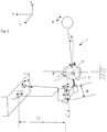
- a shift lever assembly 1 includes a gearshift lever 3 pivotally mounted about a pivot point P formed in a shift frame 5.
- the shift frame is adapted to be attached to the body of a vehicle, for example to the floor 7 or to the centre console or to the dash board or the like.
- the gearshift lever comprises an elongated shaft 9 which extends upwardly from the upper side 11 of bearing means such a pivot ball 13 which allow it to rotate in the longitudinal and transverse directions with respect to the shift frame.
- pivot point P coincides with the centre of pivot ball 13.
- An elongated first connection shaft 15 is fixed to, preferably, the lower side 17 of the pivot ball, and the longitudinal axis of the first connection shaft extends, preferably radially, downwardly from the pivot ball.
- the first connection shaft follows any movement of the gearshift lever. In this example it is is shown as being coaxial with the gearshift lever which is arranged above the pivot ball but it is conceivable that they are not coaxial. For example, they may be arranged offset and parallel to each other or at an angle to each other.
- the pivot ball 13 is mountable in a pivot bowl 19 attached to the shift frame.
- the pivot ball and pivot bowl act like a spherical ball joint and allow the gear shift lever to rotate around the central pivot point P of the pivot ball.
- the gearshift lever typically includes a proximal upper end 21 to which is attached a shift knob 23 which is suitable for being gripped by the driver.
- the gearshift lever is displaceable between positions corresponding to the different selectable gears of the gearbox. For example there may be five selectable forward gears and one reverse gear. These gears may be distributed in a so-called "double H" pattern, i.e. a pattern resembling two superimposed H's.
- the operator may rotate the gearshift lever in what is typically referred to as the select direction (i.e. right/left) about a preferably substantially longitudinal, preferably substantially horizontal selection axis X.
- the operator may rotate the gearshift lever backwards or forwards about a preferably substantially transverse, preferably substantially horizontal shift axis Y which will cause the desired gear to be engaged.
- selection axis X and shift axis Y intersect at the central pivot point P of the pivot ball of the gearshift lever but it is conceivable that they do not intersect if other types of pivoting mounting of the gearshift lever are used.
- the shift lever assembly includes a shift rod 25 which extends forwards from the shift assembly and at, or near, its distal end 26 is connectable to, and able to transfer gearshift lever movements to, the selection mechanism of the gearbox 27.
- the shift rod is connected at, or near, its proximal end 55 by a floating link 29 to the first connection shaft 15 which extends below the pivot ball.
- the floating link comprises a link body 31 with a first end 33 which comprises a nominally vertical bore 35 which is rotatably mounted around the first connection shaft 15, and a second end 37.
- the second end of the body 31 comprises a nominally vertical second bore 39 which is substantially parallel with the first vertical bore.
- the link body of the floating link is arranged with its longitudinal axis (which passes through the centres of the first and second bore) extending laterally from the longitudinal axis of the first connection shaft and the concentric, surrounding first bore at an angle ⁇ to the x-axis.
- a second connection shaft 41 is rotatably mounted in said second bore and projects out from both ends of said second bore.
- the upper first end 43 of the second connection shaft is closer to the pivot point P than the lower second end 51 of said second connection shaft.
- the first end 43 comprises a multi-axis connection means such as a ball joint 45, which connects it to the proximal end 47 of a reaction rod 49.
- the centre of the ball joint 45 is in the same horizontal plane (i.e.
- the lower second end 51 of the second connection shaft is connected by a joint 53 to the proximal end 55 of the shift rod 25.
- this joint is a single-axis joint.
- This joint comprises a substantially horizontal, substantially transverse axis 57.
- This is joint is the only connection between the proximal end of the shift rod and the other components of the shift rod assembly which is needed to ensure that movements of the gear shift lever are transmitted to the selection mechanism of the gearbox.
- the shift rod may only pivot relative to the connection shaft around this single pivot axis.
- the pivot axis of single-axis joint 53 is positioned at a predetermined distance H in the longitudinal direction of the second connection shaft below the pivot centre of the multi-axis connection means of the reaction rod, where H is preferably equal to or greater than 1 cm and equal to or less than 5 cm, more preferably equal to or greater than 1.2 cm and equal to or less than 4 cm and most preferably equal to or greater than 1.4 cm and equal to or less than 3 cm.
- H is preferably equal to or greater than 1 cm and equal to or less than 5 cm, more preferably equal to or greater than 1.2 cm and equal to or less than 4 cm and most preferably equal to or greater than 1.4 cm and equal to or less than 3 cm.
- the reaction rod extends towards the gearbox housing 59 and the distal end 61 of the reaction rod is pivotably mounted via a substantially horizontal, substantially transverse axis 63 to the gearbox housing positioned at a predetermined distance D1 to one side of the joint 65 between the shift rod and the gearbox selection mechanism 67.
- the second end 37 of the floating link is maintained by the reaction rod at a substantially fixed distance L1 from the gearbox housing, where L1 corresponds to the distance between the pivot axis of the ball joint 45 and transverse axis 63.
- the transverse axis 63 may be mounted to the gearbox housing using a rubber or other elastic bush or the transverse housing may be replaced by a spherical bearing. This allows easier mounting of the reaction rod and also allows it to be subject to some sideways and rotational forces without binding.
- the ball joint 45 between the reaction rod and the floating link provides a pivot axis for the movement of the shift rod in response to the movement of the gearshift lever.
- reaction rod which keeps the floating link stationary, rotation of the gearshift lever in the shift direction would normally only result in the rotation of the floating link around the first connection shaft and would not cause the distal end of the shift rod to shift the selection mechanism of the gearbox to the desired gear.
- the reaction rod also transfers to the floating link any longitudinal displacements of the gearbox housing relative to the body of the vehicle. Such displacements cause the floating link to be rotated around the first and second connection shafts in a manner which moves the shift rod a longitudinal distance that corresponds exactly to the longitudinal distance which the gearbox housing has been moved.
- the centre-to-centre distance D2 between the first and second bore of the floating link is the same as distance D1 so that any longitudinal movement of the gearbox housing is copied substantially exactly by the longitudinal movement of the second end of the floating link.
- the floating link is adapted to transmit rotation movement of the gearshift lever around the axis X and axis Y to the shift rod while at the same time preventing transmission of any longitudinal motion of the shift rod to the gearshift lever.
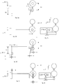
- Figure 3a shows schematically a plane view, figure 3b ) a side view and figure 3c ) an end view in the direction of arrow A of the gearbox and shift lever assembly in a first position.
- Figure 3d shows schematically a plane view, figure 3e ) a side view and figure 3f ) an end view in the direction of arrow A' of the gearbox and shift lever assembly in a second position where the gearbox has moved backwards, i.e. towards the gearshift lever, a longitudinal distance b. This movement moves the reaction rod to move back an equal amount b and the reaction rod causes the second connection shaft to move backwards the same distance b.
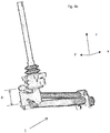
- Figures 4a) to 4e show schematically rendered views of an embodiment of a shift lever assembly according to the present invention.
- the same reference numbers are used for components corresponding to those shown in figures 1 to 3f ).
- Figure 4a ) shows a perspective view from above
- figure 4b shows a second perspective view from above
- figure 4c shows a perspective view from in front
- figure 4d shows a perspective view from below
- figure 4e shows a perspective view from behind of this embodiment of a shift lever assembly.
- the floating link extends laterally from the first connection rod at angle ⁇ .
- the angle ⁇ between body of the floating link and the longitudinal axis of the shift lever assembly changes. This change in angle changes the distance in the Y-direction between the axis of first and second connecting shafts - the distance being a maximum and equal to D2 when the angle ⁇ is 90 degrees.
- the shift lever assembly is arranged so that the floating link can rotate around the first connection shaft through an angle ⁇ which is equal to or greater than 20 degrees forwards and which is equal to or greater than 20 degrees backwards.
- ⁇ which is equal to or greater than 20 degrees forwards and which is equal to or greater than 20 degrees backwards.
- the shift lever assembly is arranged so that the floating link can rotate around the first connection shaft through an angle which is equal or greater than a total of 50 degrees and thus compensate for even larger longitudinal movement.
- the floating link is prevented from rotating more than 60 degrees in the forward direction or in the backward direction.
- the distance D2 in the Y-direction between the axis of first and second connecting shafts of the floating link is adapted to the size of the vehicle which it is intended to be used on.
- D2 is greater than or equal to 2 cm and equal to or less than 15 cm, more preferably is greater than or equal to 2.5 cm and equal to or less than 10 cm and even more preferably is greater than or equal to 3 cm and equal to or less than 5 cm.
- the shift lever assembly may be mounted to a gearbox housing to form a sub-assembly which subsequently can be mounted as a unit to the body of a vehicle.
- the shift lever assembly can be mounted to the body of a vehicle to which subsequently a gearbox can be mounted.
Landscapes
- Engineering & Computer Science (AREA)
- General Engineering & Computer Science (AREA)
- Mechanical Engineering (AREA)
- Arrangement Or Mounting Of Control Devices For Change-Speed Gearing (AREA)
- Gear-Shifting Mechanisms (AREA)
Claims (13)
- Ensemble de levier de changement de vitesse (1) pour la sélection de vitesses dans une boîte de vitesses (27) d'un véhicule, l'ensemble de levier de changement de vitesse comprenant :un levier de changement de vitesse (3) monté de manière pivotante par rapport à un point de pivotement (P) et lequel levier de changement de vitesse peut pivoter entre une pluralité de positions de sélection de vitesse et de positions de changement de vitesse,une tige de changement de vitesse (25) s'étendant longitudinalement apte à être couplée de manière fonctionnelle à son extrémité distale (26), laquelle est distale par rapport au levier de changement de vitesse (3), à un mécanisme de sélection de la boîte de vitesses (27) de sorte à être apte à transférer à la boîte de vitesses toute les commandes de changement et de sélection générées par le mouvement pivotant du levier de changement de vitesse, un mouvement de changement de vitesse du levier de changement de vitesse sera considéré comme impliquant un mouvement longitudinal dans un axe x de l'extrémité distale de la tige de changement de vitesse (25) et une rotation autour d'un axe y du levier de changement de vitesse (3) et un mouvement de sélection du levier de changement de vitesse (3) sera considéré comme impliquant un mouvement transversal dans l'axe x et une rotation du levier de changement de vitesse (3) autour de l'axe x, dans lequel l'axe y s'étend dans un plan horizontal par le point de pivotement (P) et perpendiculaire à l'axe x, et un axe z vertical s'étend par le point de pivotement et perpendiculaire au plan horizontal des axes x et y et généralement dans la direction du levier de changement de vitesse (3) ;une tige de réaction (49) s'étendant longitudinalement apte à être couplée de manière pivotante à son extrémité distale (61), laquelle est distale par rapport au levier de changement de vitesse (3), à la boîte de vitesses ;caractérisé en ce que l'ensemble de levier de changement de vitesse comprend un premier arbre de connexion (15) s'étendant dudit point de pivotement (P),dans lequel une liaison flottante (29) ayant un corps de liaison (31) avec une première extrémité (33) et une deuxième extrémité (37) est montée à ladite première extrémité (33) audit premier arbre de connexion (15) et est adaptée pour être rotative autour de l'axe longitudinal dudit premier arbre de connexion,dans lequel l'axe longitudinal de la liaison flottante (29) s'étend dudit axe longitudinal du premier arbre de connexion latéralement à un angle α par rapport à l'axe x dans le plan horizontal,dans lequel un deuxième arbre de connexion (41) est monté de manière rotative à ladite deuxième extrémité (37) de la liaison flottante (29) et est adapté pour être rotatif autour d'un axe longitudinal lequel est sensiblement parallèle à l'axe longitudinal du premier arbre de connexion (15), dans lequel le deuxième arbre de connexion (41) a une première extrémité supérieure (43) et une deuxième extrémité inférieure (51), dans lequel les termes supérieur et inférieur se réfèrent à la position relative des première et deuxième extrémités le long de l'axe z,dans lequel une extrémité proximale (47) de la tige de réaction, laquelle est opposée à son extrémité distale (61), est connectée de manière pivotante par une articulation (45) à la première extrémité supérieure (43) du deuxième arbre de connexion (41),dans lequel une extrémité proximale (55) de la tige de changement de vitesse, laquelle est opposée à son extrémité distale (26), est connectée de manière pivotante à la deuxième extrémité inférieure (51) du deuxième arbre de connexion (41) par une articulation (57), et quel'articulation (57) connectant l'extrémité proximale (55) de la tige de changement de vitesse à la deuxième extrémité inférieure (51) du deuxième arbre de connexion (41) est agencée à une distance (H) prédéterminée dans la direction longitudinale du deuxième arbre de connexion (41) de l'axe de pivotement de l'articulation (45) connectant l'extrémité proximale (47) de la tige de réaction (49) à la première extrémité supérieure du deuxième arbre de connexion (41).
- Ensemble de levier de changement de vitesse selon la revendication 1, caractérisé en ce que le premier arbre de connexion (15) est monté sur le côté du point de pivotement lequel est opposé au levier de changement de vitesse (3) par rapport au plan horizontal.
- Ensemble de levier de changement de vitesse selon la revendication 1 ou 2, caractérisé en ce que l'axe longitudinal du premier arbre de connexion (15) est aligné avec l'axe longitudinal du levier de changement de vitesse (3).
- Ensemble de levier de changement de vitesse selon l'une quelconque des revendications précédentes, caractérisé en ce qu'une distance centre-à-centre (D2) entre le premier arbre de connexion (15) et le deuxième arbre de connexion (41) est supérieure ou égale à 2 cm et égale ou inférieure à 15 cm.
- Ensemble de levier de changement de vitesse selon la revendication 4, caractérisé en ce qu'une distance centre-à-centre (D2) entre le premier arbre de connexion (15) et le deuxième arbre de connexion (41) est supérieure ou égale à 2,5 cm et égale ou inférieure à 10 cm.
- Ensemble de levier de changement de vitesse selon la revendication 5, caractérisé en ce qu'une distance centre-à-centre (D2) entre le premier arbre de connexion (15) et le deuxième arbre de connexion est supérieure ou égale à 3 cm et égale ou inférieure à 5 cm.
- Ensemble de levier de changement de vitesse selon l'une quelconque des revendications précédentes, caractérisé en ce que l'angle α est supérieur ou égal à 60 degrés et égal ou inférieur à 120 degrés.
- Ensemble de levier de changement de vitesse selon la revendication 7, caractérisé en ce que l'angle α est supérieur ou égal à 70 degrés et égal ou inférieur à 110 degrés.
- Ensemble de levier de changement de vitesse selon l'une quelconque des revendications précédentes, dans lequel la distance H est égale ou supérieure à 1 cm et égale ou inférieure à 5 cm.
- Ensemble de levier de changement de vitesse selon la revendication 9, dans lequel la distance H est égale ou supérieure à 1,2 cm et égale ou inférieure à 4 cm.
- Ensemble de levier de changement de vitesse selon la revendication 10, dans lequel la distance H est égale ou supérieure à 1,4 cm et égale ou inférieure à 3 cm.
- Ensemble d'une boîte de vitesses et d'un ensemble de levier de changement de vitesse, l'ensemble comprenant une boîte de vitesses et un ensemble de levier de changement de vitesse selon l'une quelconque des revendications précédentes.
- Ensemble d'un corps de véhicule et d'un ensemble de levier de changement de vitesse, l'ensemble comprenant un corps de véhicule et un ensemble de levier de changement de vitesse selon l'une quelconque des revendications 1 à 11.
Applications Claiming Priority (1)
| Application Number | Priority Date | Filing Date | Title |
|---|---|---|---|
| PCT/EP2015/059155 WO2016173623A1 (fr) | 2015-04-28 | 2015-04-28 | Ensemble de levier de changement de vitesse |
Publications (2)
| Publication Number | Publication Date |
|---|---|
| EP3289246A1 EP3289246A1 (fr) | 2018-03-07 |
| EP3289246B1 true EP3289246B1 (fr) | 2020-07-29 |
Family
ID=53039410
Family Applications (1)
| Application Number | Title | Priority Date | Filing Date |
|---|---|---|---|
| EP15719683.3A Active EP3289246B1 (fr) | 2015-04-28 | 2015-04-28 | Ensemble de levier de changement de vitesse |
Country Status (3)
| Country | Link |
|---|---|
| EP (1) | EP3289246B1 (fr) |
| CN (1) | CN107810349B (fr) |
| WO (1) | WO2016173623A1 (fr) |
Families Citing this family (1)
| Publication number | Priority date | Publication date | Assignee | Title |
|---|---|---|---|---|
| CN109488763A (zh) * | 2018-11-08 | 2019-03-19 | 中国科学技术大学 | 一种基于三轴加速度计的机动车挡位识别方法及系统 |
Family Cites Families (7)
| Publication number | Priority date | Publication date | Assignee | Title |
|---|---|---|---|---|
| JPS5813926B2 (ja) * | 1975-12-28 | 1983-03-16 | トヨタ自動車株式会社 | トランスミツシヨンコントロ−ルキコウ |
| DE9308072U1 (fr) * | 1993-05-28 | 1993-07-22 | Heidemann-Werke Gmbh & Co Kg, 37574 Einbeck, De | |
| DE19632859A1 (de) * | 1996-08-14 | 1998-02-19 | Bayerische Motoren Werke Ag | Betätigungseinrichtung für ein Kraftfahrzeuggetriebe |
| SE525345C2 (sv) * | 2003-06-24 | 2005-02-08 | Kongsberg Automotive Ab | Spakställ |
| DE102008015874A1 (de) * | 2008-03-26 | 2009-10-01 | Lemförder Electronic GmbH | Betätigungseinrichtung mit Haptikemulation |
| DE102008001805A1 (de) * | 2008-05-15 | 2009-11-19 | Zf Friedrichshafen Ag | Betätigungseinrichtung mit Force Feedback |
| DE102008041374A1 (de) * | 2008-08-20 | 2010-02-25 | Zf Friedrichshafen Ag | Wählhebel mit aktuatorischem Positionswechsel |
-
2015
- 2015-04-28 EP EP15719683.3A patent/EP3289246B1/fr active Active
- 2015-04-28 WO PCT/EP2015/059155 patent/WO2016173623A1/fr active Application Filing
- 2015-04-28 CN CN201580081104.2A patent/CN107810349B/zh active Active
Non-Patent Citations (1)
| Title |
|---|
| None * |
Also Published As
| Publication number | Publication date |
|---|---|
| CN107810349A (zh) | 2018-03-16 |
| EP3289246A1 (fr) | 2018-03-07 |
| WO2016173623A1 (fr) | 2016-11-03 |
| CN107810349B (zh) | 2019-06-04 |
Similar Documents
| Publication | Publication Date | Title |
|---|---|---|
| US6435054B1 (en) | Shifting device for a manual gear transmission | |
| EP0166532B1 (fr) | Mécanisme de changement de vitesses à deux câbles pour transmissions | |
| EP0918273A1 (fr) | Ensemble de pédales réglables en position | |
| JP6499111B2 (ja) | 作業車両 | |
| US5921141A (en) | Operating device for a motor vehicle transmission | |
| US4266438A (en) | Transmission shift control | |
| US4934208A (en) | Vehicle transmission shifter | |
| EP3289246B1 (fr) | Ensemble de levier de changement de vitesse | |
| EP0238182A2 (fr) | Transmetteur pour mécanisme de changement de vitesses à deux câbles | |
| US3264892A (en) | Transmission control linkage | |
| CN201487184U (zh) | 变速传动装置 | |
| US3800924A (en) | Control lever to actuate remote shift lever | |
| CA1237638A (fr) | Telecommande maitresse de passage des vitesses | |
| EP2525119B1 (fr) | Dispositif de changement de vitesses pour boîte de vitesses manuelle | |
| EP1375974B1 (fr) | Dispositif de changement de vitesse pour une transmission avec plusieurs rapports de vitesse | |
| EP1998083A1 (fr) | Système de levier de vitesse pour commander une paire de câbles de transmission | |
| JPS61234414A (ja) | 変速機の遠隔操作機構 | |
| JPH0419259Y2 (fr) | ||
| RU54562U1 (ru) | Дистанционный привод управления коробкой передач транспортного средства | |
| JP2004196158A (ja) | チェンジレバー装置 | |
| RU54121U1 (ru) | Транслятор тросового привода механизма переключения передач | |
| JP2024011917A (ja) | 変速装置 | |
| SE520718C2 (sv) | Rörelseöverföringsmekanism för en växelspakl | |
| WO2014038996A1 (fr) | Mécanisme de changement de vitesse pour véhicules comportant une cabine inclinable | |
| KR100428168B1 (ko) | 버스용 변속레버의 조작력 전달구조 |
Legal Events
| Date | Code | Title | Description |
|---|---|---|---|
| STAA | Information on the status of an ep patent application or granted ep patent |
Free format text: STATUS: THE INTERNATIONAL PUBLICATION HAS BEEN MADE |
|
| PUAI | Public reference made under article 153(3) epc to a published international application that has entered the european phase |
Free format text: ORIGINAL CODE: 0009012 |
|
| STAA | Information on the status of an ep patent application or granted ep patent |
Free format text: STATUS: REQUEST FOR EXAMINATION WAS MADE |
|
| 17P | Request for examination filed |
Effective date: 20171026 |
|
| AK | Designated contracting states |
Kind code of ref document: A1 Designated state(s): AL AT BE BG CH CY CZ DE DK EE ES FI FR GB GR HR HU IE IS IT LI LT LU LV MC MK MT NL NO PL PT RO RS SE SI SK SM TR |
|
| AX | Request for extension of the european patent |
Extension state: BA ME |
|
| DAV | Request for validation of the european patent (deleted) | ||
| DAX | Request for extension of the european patent (deleted) | ||
| GRAP | Despatch of communication of intention to grant a patent |
Free format text: ORIGINAL CODE: EPIDOSNIGR1 |
|
| STAA | Information on the status of an ep patent application or granted ep patent |
Free format text: STATUS: GRANT OF PATENT IS INTENDED |
|
| INTG | Intention to grant announced |
Effective date: 20200520 |
|
| GRAS | Grant fee paid |
Free format text: ORIGINAL CODE: EPIDOSNIGR3 |
|
| GRAA | (expected) grant |
Free format text: ORIGINAL CODE: 0009210 |
|
| STAA | Information on the status of an ep patent application or granted ep patent |
Free format text: STATUS: THE PATENT HAS BEEN GRANTED |
|
| AK | Designated contracting states |
Kind code of ref document: B1 Designated state(s): AL AT BE BG CH CY CZ DE DK EE ES FI FR GB GR HR HU IE IS IT LI LT LU LV MC MK MT NL NO PL PT RO RS SE SI SK SM TR |
|
| REG | Reference to a national code |
Ref country code: CH Ref legal event code: EP |
|
| REG | Reference to a national code |
Ref country code: AT Ref legal event code: REF Ref document number: 1296186 Country of ref document: AT Kind code of ref document: T Effective date: 20200815 |
|
| REG | Reference to a national code |
Ref country code: IE Ref legal event code: FG4D |
|
| REG | Reference to a national code |
Ref country code: DE Ref legal event code: R096 Ref document number: 602015056480 Country of ref document: DE |
|
| REG | Reference to a national code |
Ref country code: LT Ref legal event code: MG4D |
|
| REG | Reference to a national code |
Ref country code: NL Ref legal event code: MP Effective date: 20200729 |
|
| REG | Reference to a national code |
Ref country code: AT Ref legal event code: MK05 Ref document number: 1296186 Country of ref document: AT Kind code of ref document: T Effective date: 20200729 |
|
| PG25 | Lapsed in a contracting state [announced via postgrant information from national office to epo] |
Ref country code: HR Free format text: LAPSE BECAUSE OF FAILURE TO SUBMIT A TRANSLATION OF THE DESCRIPTION OR TO PAY THE FEE WITHIN THE PRESCRIBED TIME-LIMIT Effective date: 20200729 Ref country code: LT Free format text: LAPSE BECAUSE OF FAILURE TO SUBMIT A TRANSLATION OF THE DESCRIPTION OR TO PAY THE FEE WITHIN THE PRESCRIBED TIME-LIMIT Effective date: 20200729 Ref country code: GR Free format text: LAPSE BECAUSE OF FAILURE TO SUBMIT A TRANSLATION OF THE DESCRIPTION OR TO PAY THE FEE WITHIN THE PRESCRIBED TIME-LIMIT Effective date: 20201030 Ref country code: SE Free format text: LAPSE BECAUSE OF FAILURE TO SUBMIT A TRANSLATION OF THE DESCRIPTION OR TO PAY THE FEE WITHIN THE PRESCRIBED TIME-LIMIT Effective date: 20200729 Ref country code: BG Free format text: LAPSE BECAUSE OF FAILURE TO SUBMIT A TRANSLATION OF THE DESCRIPTION OR TO PAY THE FEE WITHIN THE PRESCRIBED TIME-LIMIT Effective date: 20201029 Ref country code: FI Free format text: LAPSE BECAUSE OF FAILURE TO SUBMIT A TRANSLATION OF THE DESCRIPTION OR TO PAY THE FEE WITHIN THE PRESCRIBED TIME-LIMIT Effective date: 20200729 Ref country code: AT Free format text: LAPSE BECAUSE OF FAILURE TO SUBMIT A TRANSLATION OF THE DESCRIPTION OR TO PAY THE FEE WITHIN THE PRESCRIBED TIME-LIMIT Effective date: 20200729 Ref country code: NO Free format text: LAPSE BECAUSE OF FAILURE TO SUBMIT A TRANSLATION OF THE DESCRIPTION OR TO PAY THE FEE WITHIN THE PRESCRIBED TIME-LIMIT Effective date: 20201029 Ref country code: PT Free format text: LAPSE BECAUSE OF FAILURE TO SUBMIT A TRANSLATION OF THE DESCRIPTION OR TO PAY THE FEE WITHIN THE PRESCRIBED TIME-LIMIT Effective date: 20201130 Ref country code: ES Free format text: LAPSE BECAUSE OF FAILURE TO SUBMIT A TRANSLATION OF THE DESCRIPTION OR TO PAY THE FEE WITHIN THE PRESCRIBED TIME-LIMIT Effective date: 20200729 |
|
| PG25 | Lapsed in a contracting state [announced via postgrant information from national office to epo] |
Ref country code: RS Free format text: LAPSE BECAUSE OF FAILURE TO SUBMIT A TRANSLATION OF THE DESCRIPTION OR TO PAY THE FEE WITHIN THE PRESCRIBED TIME-LIMIT Effective date: 20200729 Ref country code: PL Free format text: LAPSE BECAUSE OF FAILURE TO SUBMIT A TRANSLATION OF THE DESCRIPTION OR TO PAY THE FEE WITHIN THE PRESCRIBED TIME-LIMIT Effective date: 20200729 Ref country code: LV Free format text: LAPSE BECAUSE OF FAILURE TO SUBMIT A TRANSLATION OF THE DESCRIPTION OR TO PAY THE FEE WITHIN THE PRESCRIBED TIME-LIMIT Effective date: 20200729 Ref country code: IS Free format text: LAPSE BECAUSE OF FAILURE TO SUBMIT A TRANSLATION OF THE DESCRIPTION OR TO PAY THE FEE WITHIN THE PRESCRIBED TIME-LIMIT Effective date: 20201129 |
|
| PG25 | Lapsed in a contracting state [announced via postgrant information from national office to epo] |
Ref country code: NL Free format text: LAPSE BECAUSE OF FAILURE TO SUBMIT A TRANSLATION OF THE DESCRIPTION OR TO PAY THE FEE WITHIN THE PRESCRIBED TIME-LIMIT Effective date: 20200729 |
|
| PG25 | Lapsed in a contracting state [announced via postgrant information from national office to epo] |
Ref country code: DK Free format text: LAPSE BECAUSE OF FAILURE TO SUBMIT A TRANSLATION OF THE DESCRIPTION OR TO PAY THE FEE WITHIN THE PRESCRIBED TIME-LIMIT Effective date: 20200729 Ref country code: CZ Free format text: LAPSE BECAUSE OF FAILURE TO SUBMIT A TRANSLATION OF THE DESCRIPTION OR TO PAY THE FEE WITHIN THE PRESCRIBED TIME-LIMIT Effective date: 20200729 Ref country code: RO Free format text: LAPSE BECAUSE OF FAILURE TO SUBMIT A TRANSLATION OF THE DESCRIPTION OR TO PAY THE FEE WITHIN THE PRESCRIBED TIME-LIMIT Effective date: 20200729 Ref country code: SM Free format text: LAPSE BECAUSE OF FAILURE TO SUBMIT A TRANSLATION OF THE DESCRIPTION OR TO PAY THE FEE WITHIN THE PRESCRIBED TIME-LIMIT Effective date: 20200729 Ref country code: EE Free format text: LAPSE BECAUSE OF FAILURE TO SUBMIT A TRANSLATION OF THE DESCRIPTION OR TO PAY THE FEE WITHIN THE PRESCRIBED TIME-LIMIT Effective date: 20200729 |
|
| REG | Reference to a national code |
Ref country code: DE Ref legal event code: R097 Ref document number: 602015056480 Country of ref document: DE |
|
| PG25 | Lapsed in a contracting state [announced via postgrant information from national office to epo] |
Ref country code: AL Free format text: LAPSE BECAUSE OF FAILURE TO SUBMIT A TRANSLATION OF THE DESCRIPTION OR TO PAY THE FEE WITHIN THE PRESCRIBED TIME-LIMIT Effective date: 20200729 |
|
| PLBE | No opposition filed within time limit |
Free format text: ORIGINAL CODE: 0009261 |
|
| STAA | Information on the status of an ep patent application or granted ep patent |
Free format text: STATUS: NO OPPOSITION FILED WITHIN TIME LIMIT |
|
| PG25 | Lapsed in a contracting state [announced via postgrant information from national office to epo] |
Ref country code: SK Free format text: LAPSE BECAUSE OF FAILURE TO SUBMIT A TRANSLATION OF THE DESCRIPTION OR TO PAY THE FEE WITHIN THE PRESCRIBED TIME-LIMIT Effective date: 20200729 |
|
| 26N | No opposition filed |
Effective date: 20210430 |
|
| PG25 | Lapsed in a contracting state [announced via postgrant information from national office to epo] |
Ref country code: SI Free format text: LAPSE BECAUSE OF FAILURE TO SUBMIT A TRANSLATION OF THE DESCRIPTION OR TO PAY THE FEE WITHIN THE PRESCRIBED TIME-LIMIT Effective date: 20200729 |
|
| REG | Reference to a national code |
Ref country code: DE Ref legal event code: R119 Ref document number: 602015056480 Country of ref document: DE |
|
| PG25 | Lapsed in a contracting state [announced via postgrant information from national office to epo] |
Ref country code: MC Free format text: LAPSE BECAUSE OF FAILURE TO SUBMIT A TRANSLATION OF THE DESCRIPTION OR TO PAY THE FEE WITHIN THE PRESCRIBED TIME-LIMIT Effective date: 20200729 |
|
| GBPC | Gb: european patent ceased through non-payment of renewal fee |
Effective date: 20210428 |
|
| PG25 | Lapsed in a contracting state [announced via postgrant information from national office to epo] |
Ref country code: LU Free format text: LAPSE BECAUSE OF NON-PAYMENT OF DUE FEES Effective date: 20210428 |
|
| REG | Reference to a national code |
Ref country code: BE Ref legal event code: MM Effective date: 20210430 |
|
| PG25 | Lapsed in a contracting state [announced via postgrant information from national office to epo] |
Ref country code: LI Free format text: LAPSE BECAUSE OF NON-PAYMENT OF DUE FEES Effective date: 20210430 Ref country code: CH Free format text: LAPSE BECAUSE OF NON-PAYMENT OF DUE FEES Effective date: 20210430 Ref country code: GB Free format text: LAPSE BECAUSE OF NON-PAYMENT OF DUE FEES Effective date: 20210428 Ref country code: DE Free format text: LAPSE BECAUSE OF NON-PAYMENT OF DUE FEES Effective date: 20211103 |
|
| PG25 | Lapsed in a contracting state [announced via postgrant information from national office to epo] |
Ref country code: IE Free format text: LAPSE BECAUSE OF NON-PAYMENT OF DUE FEES Effective date: 20210428 |
|
| PG25 | Lapsed in a contracting state [announced via postgrant information from national office to epo] |
Ref country code: IS Free format text: LAPSE BECAUSE OF FAILURE TO SUBMIT A TRANSLATION OF THE DESCRIPTION OR TO PAY THE FEE WITHIN THE PRESCRIBED TIME-LIMIT Effective date: 20201129 |
|
| PG25 | Lapsed in a contracting state [announced via postgrant information from national office to epo] |
Ref country code: BE Free format text: LAPSE BECAUSE OF NON-PAYMENT OF DUE FEES Effective date: 20210430 |
|
| PGFP | Annual fee paid to national office [announced via postgrant information from national office to epo] |
Ref country code: FR Payment date: 20230328 Year of fee payment: 9 |
|
| PG25 | Lapsed in a contracting state [announced via postgrant information from national office to epo] |
Ref country code: HU Free format text: LAPSE BECAUSE OF FAILURE TO SUBMIT A TRANSLATION OF THE DESCRIPTION OR TO PAY THE FEE WITHIN THE PRESCRIBED TIME-LIMIT; INVALID AB INITIO Effective date: 20150428 |
|
| PGFP | Annual fee paid to national office [announced via postgrant information from national office to epo] |
Ref country code: IT Payment date: 20230310 Year of fee payment: 9 |
|
| PG25 | Lapsed in a contracting state [announced via postgrant information from national office to epo] |
Ref country code: CY Free format text: LAPSE BECAUSE OF FAILURE TO SUBMIT A TRANSLATION OF THE DESCRIPTION OR TO PAY THE FEE WITHIN THE PRESCRIBED TIME-LIMIT Effective date: 20200729 |
|
| PG25 | Lapsed in a contracting state [announced via postgrant information from national office to epo] |
Ref country code: MK Free format text: LAPSE BECAUSE OF FAILURE TO SUBMIT A TRANSLATION OF THE DESCRIPTION OR TO PAY THE FEE WITHIN THE PRESCRIBED TIME-LIMIT Effective date: 20200729 |