EP3288685B1 - Servo operated spray machine and method for operating - Google Patents
Servo operated spray machine and method for operating Download PDFInfo
- Publication number
- EP3288685B1 EP3288685B1 EP16716643.8A EP16716643A EP3288685B1 EP 3288685 B1 EP3288685 B1 EP 3288685B1 EP 16716643 A EP16716643 A EP 16716643A EP 3288685 B1 EP3288685 B1 EP 3288685B1
- Authority
- EP
- European Patent Office
- Prior art keywords
- machines
- controller
- internal spray
- spray machines
- servo
- Prior art date
- Legal status (The legal status is an assumption and is not a legal conclusion. Google has not performed a legal analysis and makes no representation as to the accuracy of the status listed.)
- Active
Links
Images


Classifications
-
- B—PERFORMING OPERATIONS; TRANSPORTING
- B05—SPRAYING OR ATOMISING IN GENERAL; APPLYING FLUENT MATERIALS TO SURFACES, IN GENERAL
- B05B—SPRAYING APPARATUS; ATOMISING APPARATUS; NOZZLES
- B05B11/00—Single-unit hand-held apparatus in which flow of contents is produced by the muscular force of the operator at the moment of use
- B05B11/01—Single-unit hand-held apparatus in which flow of contents is produced by the muscular force of the operator at the moment of use characterised by the means producing the flow
- B05B11/02—Membranes or pistons acting on the contents inside the container, e.g. follower pistons
-
- B—PERFORMING OPERATIONS; TRANSPORTING
- B05—SPRAYING OR ATOMISING IN GENERAL; APPLYING FLUENT MATERIALS TO SURFACES, IN GENERAL
- B05B—SPRAYING APPARATUS; ATOMISING APPARATUS; NOZZLES
- B05B13/00—Machines or plants for applying liquids or other fluent materials to surfaces of objects or other work by spraying, not covered by groups B05B1/00 - B05B11/00
- B05B13/06—Machines or plants for applying liquids or other fluent materials to surfaces of objects or other work by spraying, not covered by groups B05B1/00 - B05B11/00 specially designed for treating the inside of hollow bodies
- B05B13/0645—Machines or plants for applying liquids or other fluent materials to surfaces of objects or other work by spraying, not covered by groups B05B1/00 - B05B11/00 specially designed for treating the inside of hollow bodies the hollow bodies being rotated during treatment operation
-
- B—PERFORMING OPERATIONS; TRANSPORTING
- B05—SPRAYING OR ATOMISING IN GENERAL; APPLYING FLUENT MATERIALS TO SURFACES, IN GENERAL
- B05B—SPRAYING APPARATUS; ATOMISING APPARATUS; NOZZLES
- B05B13/00—Machines or plants for applying liquids or other fluent materials to surfaces of objects or other work by spraying, not covered by groups B05B1/00 - B05B11/00
- B05B13/02—Means for supporting work; Arrangement or mounting of spray heads; Adaptation or arrangement of means for feeding work
- B05B13/0221—Means for supporting work; Arrangement or mounting of spray heads; Adaptation or arrangement of means for feeding work characterised by the means for moving or conveying the objects or other work, e.g. conveyor belts
- B05B13/0242—Means for supporting work; Arrangement or mounting of spray heads; Adaptation or arrangement of means for feeding work characterised by the means for moving or conveying the objects or other work, e.g. conveyor belts the objects being individually presented to the spray heads by a rotating element, e.g. turntable
-
- B—PERFORMING OPERATIONS; TRANSPORTING
- B05—SPRAYING OR ATOMISING IN GENERAL; APPLYING FLUENT MATERIALS TO SURFACES, IN GENERAL
- B05B—SPRAYING APPARATUS; ATOMISING APPARATUS; NOZZLES
- B05B13/00—Machines or plants for applying liquids or other fluent materials to surfaces of objects or other work by spraying, not covered by groups B05B1/00 - B05B11/00
- B05B13/06—Machines or plants for applying liquids or other fluent materials to surfaces of objects or other work by spraying, not covered by groups B05B1/00 - B05B11/00 specially designed for treating the inside of hollow bodies
- B05B13/0609—Machines or plants for applying liquids or other fluent materials to surfaces of objects or other work by spraying, not covered by groups B05B1/00 - B05B11/00 specially designed for treating the inside of hollow bodies the hollow bodies being automatically fed to, or removed from, the machine
-
- B—PERFORMING OPERATIONS; TRANSPORTING
- B05—SPRAYING OR ATOMISING IN GENERAL; APPLYING FLUENT MATERIALS TO SURFACES, IN GENERAL
- B05B—SPRAYING APPARATUS; ATOMISING APPARATUS; NOZZLES
- B05B13/00—Machines or plants for applying liquids or other fluent materials to surfaces of objects or other work by spraying, not covered by groups B05B1/00 - B05B11/00
- B05B13/06—Machines or plants for applying liquids or other fluent materials to surfaces of objects or other work by spraying, not covered by groups B05B1/00 - B05B11/00 specially designed for treating the inside of hollow bodies
- B05B13/0645—Machines or plants for applying liquids or other fluent materials to surfaces of objects or other work by spraying, not covered by groups B05B1/00 - B05B11/00 specially designed for treating the inside of hollow bodies the hollow bodies being rotated during treatment operation
- B05B13/0681—Machines or plants for applying liquids or other fluent materials to surfaces of objects or other work by spraying, not covered by groups B05B1/00 - B05B11/00 specially designed for treating the inside of hollow bodies the hollow bodies being rotated during treatment operation the hollow bodies comprising a closed end to be treated
-
- G—PHYSICS
- G05—CONTROLLING; REGULATING
- G05B—CONTROL OR REGULATING SYSTEMS IN GENERAL; FUNCTIONAL ELEMENTS OF SUCH SYSTEMS; MONITORING OR TESTING ARRANGEMENTS FOR SUCH SYSTEMS OR ELEMENTS
- G05B19/00—Program-control systems
- G05B19/02—Program-control systems electric
- G05B19/18—Numerical control [NC], i.e. automatically operating machines, in particular machine tools, e.g. in a manufacturing environment, so as to execute positioning, movement or co-ordinated operations by means of program data in numerical form
-
- G—PHYSICS
- G05—CONTROLLING; REGULATING
- G05B—CONTROL OR REGULATING SYSTEMS IN GENERAL; FUNCTIONAL ELEMENTS OF SUCH SYSTEMS; MONITORING OR TESTING ARRANGEMENTS FOR SUCH SYSTEMS OR ELEMENTS
- G05B19/00—Program-control systems
- G05B19/02—Program-control systems electric
- G05B19/418—Total factory control, i.e. centrally controlling a plurality of machines, e.g. direct or distributed numerical control [DNC], flexible manufacturing systems [FMS], integrated manufacturing systems [IMS] or computer integrated manufacturing [CIM]
-
- H—ELECTRICITY
- H05—ELECTRIC TECHNIQUES NOT OTHERWISE PROVIDED FOR
- H05K—PRINTED CIRCUITS; CASINGS OR CONSTRUCTIONAL DETAILS OF ELECTRIC APPARATUS; MANUFACTURE OF ASSEMBLAGES OF ELECTRICAL COMPONENTS
- H05K13/00—Apparatus or processes specially adapted for manufacturing or adjusting assemblages of electric components
- H05K13/04—Mounting of components, e.g. of leadless components
- H05K13/0404—Pick-and-place heads or apparatus, e.g. with jaws
- H05K13/0411—Pick-and-place heads or apparatus, e.g. with jaws having multiple mounting heads
Definitions
- the invention relates to servo operated can internal spray machines.
- the invention relates to a method of operating the spray machines to improve energy efficiency, and a controller and spray machines for implementing the method.
- a spray machine in the can production line. Typically, such a machine will run at 300-400 cans per minute.
- the cans (1) are fed into the top of the machine by a trackwork (2), and securely attached to a "spinner pad” (3) using vacuum suction.
- the spinner pads (3) (usually 6 or 12 to a machine) are arranged around a central turret (4) which indexes (i.e. moves the cans to the processing area at the appropriate times).
- the spinner pad (3) causes the attached can (1) to rotate, e.g. at speeds of around 2200 rev/min.
- Each index of the turret (4) moves a rotating can (1) in front of a spray gun (5), which is timed to dispense a lacquer for a set time period (typically 100ms).
- the indexing mechanism must therefore provide a 'dwell' (i.e. a period of time where the can is rotating in place) corresponding to the period in which the lacquer is applied.
- the indexing mechanism will provide an acceleration phase, a deceleration phase, and a dwell, with the acceleration and deceleration being sufficient to move the cans into the required position. There may also be a period between the acceleration and deceleration where the speed is constant.
- a spray machine will typically have two or three spray guns, which ensures coverage along the length of the can body.
- the can After passing in front of the spray guns, the can is discharged from the machine, for example via a discharge turret which grips the can body, or out of the bottom of the machine via a further trackwork (6).
- the mechanical indexing box comprises an internal cam which operates to rotate the turret with the desired acceleration profile.
- the dwell time is therefore a inversely proportional to the rotational speed of the turret, which means that in order to achieve a consistent dwell time the machine must be run at the same speed.
- the spray machine In a production line where other machines are able to modulate their speed smoothly, the spray machine must be regularly stopped in order to match the flow of cans from the other machines. This can lead to blockages due to lacquer drying in the spray guns.
- Recent machines incorporate a servo motor (7) in place of the mechanical indexing box in order to overcome these problems.
- the dwell time may be maintained whilst still allowing the overall speed of the machine to be changed according to demand. This leads to a smoother flow of cans, and reduces the necessity to stop the machine and risk blocked nozzles.
- Such a servo-operated spray machine is disclosed in EP 2293881 B1 .
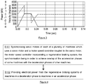
- a method of operating a plurality of machines uses a servo motor and a motor speed controller coupled to the servo motor, and the motor speed controller incorporates a regenerative braking system.
- the method comprises synchronising the servo motors in order to achieve overlap of the acceleration phases of some machines with the deceleration phases of other machines and providing electrical power from the regenerative braking systems of machines in a deceleration phase to machines in an acceleration phase.
- a controller configured to operate a plurality of machines.
- Each of the machines uses a servo motor and a motor speed controller coupled to the servo motor, and the motor speed controller incorporates a regenerative braking system, with electrical power being redistributed between machines.
- the controller is configured to synchronise the servo motors to achieve overlap of the acceleration phases of some machines with the deceleration phases of other machines.
- a system comprising a controller according to the second aspect, and a plurality of machines each of which comprises a servo motor and a motor speed controller coupled to the servo motor, the motor speed controller incorporating a regenerative braking system, wherein the controller is configured to operate the machines.
- Spray machines incorporating a servo motor will typically undergo up to 420 acceleration and deceleration cycles a minute. When servo motors decelerate, an electrical current is generated. In known servo operated spray machines, this current is directed through a "braking resistor” and allowed to dissipate as heat, as disclosed, for example, in DE 10 2009 032 739 A1 or DE 10 2013 010462 A1 .
- regenerative braking systems which convert the current generated by deceleration into usable power which can be used by other devices or stored for later use.
- power storage will generally involve losses, and requires further components to be provided, significantly reducing the potential savings from regenerating braking, and so these systems have not been considered for spray machines.
- Spray machines are typically placed in banks, generally containing seven to ten spray machines, each of which operates independently.
- a new way of operating such a bank of spray machines is proposed herein to allow a bank of machines to make better use of power generated from regenerative braking. It is recognised that there is no need for the spray machines to operate in synchronisation with one another. It is therefore proposed to control the bank of machines in such a way that when one machine (A) in the bank is in a decelerating phase, another machine (B) in the bank is in an accelerating phase, and therefore the electricity generated by the machine (A) can be used to reduce the external mains electricity required to operate machine (B). Applying this to all of the machines in a bank of seven to ten machines would allow such an overlap to occur for most of the acceleration phases of the machines, significantly reducing power consumption.
- FIG. 2 illustrates a possible synchronisation scheme for seven machines running at 420 stops per minute, with each machine having a cycle labelled 1 to 7.
- 420 stops per minute gives a total cycle time of 1/7 of a second, approx. 143ms, which means that each machine has a 100ms dwell, a 21ms acceleration phase, and a 21ms deceleration phase.
- the acceleration phase is shown as +1 on each graph, the deceleration phase as -1, and the dwell as 0.
- the acceleration and deceleration phases can be matched up so that each acceleration phase corresponds to the deceleration phase of the previous machine, i.e. the acceleration phase of machine 2 occurs simultaneously with the deceleration phase of machine 1.
- Figure 2 relates to an idealised situation where each machine is operating at the same constant rate, the acceleration and deceleration phases are equal, and there is no period of constant velocity between the acceleration and deceleration phases. This may not be the case, the machines may operate at different rates, and the rate of each machine may change over time, e.g. due to changes in the rates of other machines in the production line.
- the acceleration and deceleration phases may be varied, provided the minimum dwell time and required stops per minute are achieved, and the motion of the cans is sufficient to move them into the required position.
- each machine in the bank will run at the same rate (though this rate may change frequently).
- a typical velocity profile is shown in Figure 3 , with the red line representing velocity and the yellow line representing the power input/output of the servo motor.
- the power input during acceleration and output during deceleration are very similar.
- the required synchronisation may be achieved, for example, by starting the machines out of phase with each other, so that each machine begins its acceleration phase as the previous machine begins its deceleration phase.
- the spray machines are typically fed power via a DC voltage bus, with one bus for each spray machine. To enable power to be transferred between the machines easily, it is proposed that all of the spray machines in a bank be connected to the same DC voltage bus, and that the regenerative braking systems feed power into this bus during the deceleration phase.
- FIG. 4 A flowchart for the generic method is shown in Figure 4 .
- the machines use a servo motor and a motor speed controller coupled to the servo motor, the motor speed controller incorporating a regenerative braking system, and the servo motors are synchronised in order to achieve overlap of the acceleration phases of some of the machines with the deceleration phases of the other machines S101. Electrical power is provided from the regenerative braking systems of machines in a deceleration phase to machines in an acceleration phase S102.
- the servo motors may be synchronised in order to maximise total overlap between acceleration and deceleration phases of the machines.
- this method only applies where there are multiple machines present. This allows the savings of regenerative braking to be maximised, as there are no losses relating to the need to store the energy between a deceleration phase and an acceleration phase.
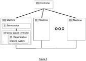
- FIG. 5 is a schematic diagram of system 100.
- the system comprises a controller 200 and a plurality of spray machines 300, 301, 30X.
- Each machine comprises a servo motor 31 and a motor speed controller 32 coupled to the servo motor, the motor speed controller incorporating a regenerative braking system 33 (shown in machine 300), and the machines are connected in order to allow power to be redistributed between the machines.
- the controller may be a single unit, which is connected to each machine, as shown in Figure 5 .
- the controller may be implemented as a distributed unit, with processors in each of the machines cooperating in order to act as the controller.
Landscapes
- Engineering & Computer Science (AREA)
- Manufacturing & Machinery (AREA)
- Physics & Mathematics (AREA)
- General Physics & Mathematics (AREA)
- Automation & Control Theory (AREA)
- General Engineering & Computer Science (AREA)
- Quality & Reliability (AREA)
- Human Computer Interaction (AREA)
- Control Of Multiple Motors (AREA)
- Spray Control Apparatus (AREA)
- Application Of Or Painting With Fluid Materials (AREA)
- Control Of Electric Motors In General (AREA)
Priority Applications (1)
| Application Number | Priority Date | Filing Date | Title |
|---|---|---|---|
| PL16716643T PL3288685T3 (pl) | 2015-04-28 | 2016-04-06 | Urządzenie natryskowe z serwomotorem i sposób obsługi |
Applications Claiming Priority (2)
| Application Number | Priority Date | Filing Date | Title |
|---|---|---|---|
| GB1507225.9A GB2537861B (en) | 2015-04-28 | 2015-04-28 | Servo operated spray machine |
| PCT/GB2016/050961 WO2016174391A1 (en) | 2015-04-28 | 2016-04-06 | Servo operated spray machine and method for operating |
Publications (2)
| Publication Number | Publication Date |
|---|---|
| EP3288685A1 EP3288685A1 (en) | 2018-03-07 |
| EP3288685B1 true EP3288685B1 (en) | 2020-07-01 |
Family
ID=53488784
Family Applications (1)
| Application Number | Title | Priority Date | Filing Date |
|---|---|---|---|
| EP16716643.8A Active EP3288685B1 (en) | 2015-04-28 | 2016-04-06 | Servo operated spray machine and method for operating |
Country Status (11)
| Country | Link |
|---|---|
| US (1) | US11679400B2 (pl) |
| EP (1) | EP3288685B1 (pl) |
| JP (1) | JP6751405B2 (pl) |
| CN (1) | CN105013643B (pl) |
| AU (1) | AU2016256653B2 (pl) |
| BR (1) | BR112017022826B1 (pl) |
| ES (1) | ES2817525T3 (pl) |
| GB (1) | GB2537861B (pl) |
| MX (1) | MX378482B (pl) |
| PL (1) | PL3288685T3 (pl) |
| WO (1) | WO2016174391A1 (pl) |
Families Citing this family (4)
| Publication number | Priority date | Publication date | Assignee | Title |
|---|---|---|---|---|
| USD946405S1 (en) | 2019-03-20 | 2022-03-22 | Ball Corporation | Metal food container |
| USD982458S1 (en) | 2019-10-24 | 2023-04-04 | Ball Corporation | Metal food container |
| CN111367242A (zh) * | 2020-02-18 | 2020-07-03 | 浙江日鼎涂装科技有限公司 | 一种智能型全自动涂装生产线生产监测方法 |
| US12168551B2 (en) | 2021-03-01 | 2024-12-17 | Ball Corporation | Metal container and end closure with seal |
Citations (4)
| Publication number | Priority date | Publication date | Assignee | Title |
|---|---|---|---|---|
| EP1791246A2 (en) * | 2005-11-25 | 2007-05-30 | ABB Oy | Frequency converter assembly and method of using frequency converter assembly |
| US20080079373A1 (en) * | 2006-09-29 | 2008-04-03 | Reliance Electric Technologies, Llc | Electric braking of machinery with a plurality of inverter-fed motors |
| EP2456063A2 (de) * | 2010-11-23 | 2012-05-23 | Schneider Electric Automation Gmbh | Erfassung der Energieverteilung in einer Maschine mit mehreren Antrieben |
| DE102013010462A1 (de) * | 2013-06-24 | 2014-03-27 | Daimler Ag | Produktionsanordnung mit wenigstens zwei Antriebssystemen |
Family Cites Families (14)
| Publication number | Priority date | Publication date | Assignee | Title |
|---|---|---|---|---|
| US3771032A (en) * | 1972-06-07 | 1973-11-06 | B Hender | Plural electric motor control systems |
| JPH04322196A (ja) * | 1991-04-22 | 1992-11-12 | Fuji Electric Co Ltd | 複数モータの駆動方法 |
| JPH05250017A (ja) * | 1992-03-09 | 1993-09-28 | Nachi Fujikoshi Corp | 産業用ロボットの同期方法 |
| JPH08300345A (ja) * | 1995-05-11 | 1996-11-19 | Tokyo Seimitsu Co Ltd | ワイヤソーの電力供給方法 |
| WO2007018899A2 (en) * | 2005-07-22 | 2007-02-15 | Nova Chemicals Inc. | System, apparatus and process for coating and curing disposable containers |
| US20070296281A1 (en) * | 2006-06-07 | 2007-12-27 | Husky Injection Molding Systems Ltd. | Electrical motor |
| US7784319B2 (en) * | 2008-04-24 | 2010-08-31 | Crown, Packaging Technology, Inc | Systems and methods for monitoring and controlling a can necking process |
| PL2293881T3 (pl) * | 2008-05-19 | 2015-03-31 | Rexam Beverage Can Co | Aparat i sposób do natryskiwania z podwójną serwolancą |
| JP4575483B2 (ja) * | 2008-09-24 | 2010-11-04 | ファナック株式会社 | 消費電力量および回生電力量を計算するサーボモータ駆動制御装置 |
| DE102009032739A1 (de) * | 2009-07-11 | 2011-01-13 | Powercut Gmbh | Werkzeugmaschine und Verfahren zum Betreiben einer solchen |
| JP5606136B2 (ja) * | 2010-04-26 | 2014-10-15 | 富士機械製造株式会社 | 部品実装機 |
| JP5212428B2 (ja) * | 2010-07-08 | 2013-06-19 | 村田機械株式会社 | 走行車システム |
| JP2012040665A (ja) * | 2010-08-23 | 2012-03-01 | Seiko Epson Corp | ロボット、ロボットの駆動方法 |
| FR2965491B1 (fr) * | 2010-10-05 | 2013-05-17 | Sgd Sa | Procede de revetement et machine de revetement correspondante |
-
2015
- 2015-04-28 GB GB1507225.9A patent/GB2537861B/en active Active
- 2015-06-18 CN CN201510342291.7A patent/CN105013643B/zh active Active
-
2016
- 2016-04-06 ES ES16716643T patent/ES2817525T3/es active Active
- 2016-04-06 AU AU2016256653A patent/AU2016256653B2/en active Active
- 2016-04-06 BR BR112017022826-2A patent/BR112017022826B1/pt active IP Right Grant
- 2016-04-06 WO PCT/GB2016/050961 patent/WO2016174391A1/en not_active Ceased
- 2016-04-06 MX MX2017013060A patent/MX378482B/es unknown
- 2016-04-06 US US15/570,088 patent/US11679400B2/en active Active
- 2016-04-06 EP EP16716643.8A patent/EP3288685B1/en active Active
- 2016-04-06 PL PL16716643T patent/PL3288685T3/pl unknown
- 2016-04-06 JP JP2017549510A patent/JP6751405B2/ja active Active
Patent Citations (4)
| Publication number | Priority date | Publication date | Assignee | Title |
|---|---|---|---|---|
| EP1791246A2 (en) * | 2005-11-25 | 2007-05-30 | ABB Oy | Frequency converter assembly and method of using frequency converter assembly |
| US20080079373A1 (en) * | 2006-09-29 | 2008-04-03 | Reliance Electric Technologies, Llc | Electric braking of machinery with a plurality of inverter-fed motors |
| EP2456063A2 (de) * | 2010-11-23 | 2012-05-23 | Schneider Electric Automation Gmbh | Erfassung der Energieverteilung in einer Maschine mit mehreren Antrieben |
| DE102013010462A1 (de) * | 2013-06-24 | 2014-03-27 | Daimler Ag | Produktionsanordnung mit wenigstens zwei Antriebssystemen |
Also Published As
| Publication number | Publication date |
|---|---|
| GB201507225D0 (en) | 2015-06-10 |
| EP3288685A1 (en) | 2018-03-07 |
| WO2016174391A1 (en) | 2016-11-03 |
| CN105013643B (zh) | 2018-07-13 |
| GB2537861A (en) | 2016-11-02 |
| BR112017022826A2 (pt) | 2018-07-17 |
| GB2537861B (en) | 2017-10-18 |
| JP6751405B2 (ja) | 2020-09-02 |
| AU2016256653A1 (en) | 2017-10-26 |
| JP2018515326A (ja) | 2018-06-14 |
| PL3288685T3 (pl) | 2021-02-08 |
| MX378482B (es) | 2025-03-11 |
| AU2016256653B2 (en) | 2020-09-10 |
| US11679400B2 (en) | 2023-06-20 |
| US20180133732A1 (en) | 2018-05-17 |
| ES2817525T3 (es) | 2021-04-07 |
| CN105013643A (zh) | 2015-11-04 |
| MX2017013060A (es) | 2017-12-08 |
| BR112017022826B1 (pt) | 2020-12-15 |
Similar Documents
| Publication | Publication Date | Title |
|---|---|---|
| EP3288685B1 (en) | Servo operated spray machine and method for operating | |
| US8590358B2 (en) | Apparatus for forming metal container comprising one or more devices that are electronically coordinated to perform operations of local and/or extensive deformation of metal containers | |
| US9643232B2 (en) | Servo press line operation method and servo press line operation control device | |
| CN107206593A (zh) | 用于协调地控制至少两个操纵器的操纵器系统 | |
| CN103042715A (zh) | 液压机节能控制系统及方法 | |
| CA2967055A1 (en) | Method for smoothly starting hall-less motor | |
| US11366446B2 (en) | Modular control of a linear drive with communication | |
| JP2011177014A (ja) | 非鉄金属から成形物を製造するための金属押出加工機 | |
| US20170222590A1 (en) | Three-phase switched reluctance motor torque ripple two-level suppression method | |
| JP2010260094A (ja) | サーボプレス装置の制御方法および装置 | |
| RU2668369C2 (ru) | Намоточная машина для намотки нескольких рулонов прокатанного материала вокруг одного барабана | |
| CN202986164U (zh) | 液压机节能控制系统 | |
| US7832385B1 (en) | Ripple reduction in electromagnetic launcher current from pulsed alternators | |
| US20210040933A1 (en) | Wind turbine blade pitch system | |
| CN104723901B (zh) | 一种集成转矩和驱动系统的分配控制器及方法 | |
| AU2018355113B2 (en) | Electronic braking system for an irrigation machine | |
| CN109179164A (zh) | 一种用于高速电梯的减振系统及减振方法 | |
| CN203909505U (zh) | 桥式双起重机小车控制电路 | |
| CN104668761A (zh) | 一种电阻焊接机传动结构 | |
| CN106041915A (zh) | 一种管道机器人移动臂或转动臂复位控制机构 | |
| EP3469698B1 (en) | Method and apparatus for operating an electric motor | |
| CN104477334B (zh) | 一种舵机舱 | |
| CN205141933U (zh) | 内置控制器的无刷电机 | |
| WO2016105249A1 (ru) | Урбамобильная транспортная система и способ ее эксплуатации | |
| CN205195613U (zh) | 一种交流力矩电机的控制装置 |
Legal Events
| Date | Code | Title | Description |
|---|---|---|---|
| STAA | Information on the status of an ep patent application or granted ep patent |
Free format text: STATUS: THE INTERNATIONAL PUBLICATION HAS BEEN MADE |
|
| PUAI | Public reference made under article 153(3) epc to a published international application that has entered the european phase |
Free format text: ORIGINAL CODE: 0009012 |
|
| STAA | Information on the status of an ep patent application or granted ep patent |
Free format text: STATUS: REQUEST FOR EXAMINATION WAS MADE |
|
| 17P | Request for examination filed |
Effective date: 20170920 |
|
| AK | Designated contracting states |
Kind code of ref document: A1 Designated state(s): AL AT BE BG CH CY CZ DE DK EE ES FI FR GB GR HR HU IE IS IT LI LT LU LV MC MK MT NL NO PL PT RO RS SE SI SK SM TR |
|
| AX | Request for extension of the european patent |
Extension state: BA ME |
|
| DAV | Request for validation of the european patent (deleted) | ||
| DAX | Request for extension of the european patent (deleted) | ||
| STAA | Information on the status of an ep patent application or granted ep patent |
Free format text: STATUS: EXAMINATION IS IN PROGRESS |
|
| 17Q | First examination report despatched |
Effective date: 20181210 |
|
| GRAP | Despatch of communication of intention to grant a patent |
Free format text: ORIGINAL CODE: EPIDOSNIGR1 |
|
| STAA | Information on the status of an ep patent application or granted ep patent |
Free format text: STATUS: GRANT OF PATENT IS INTENDED |
|
| INTG | Intention to grant announced |
Effective date: 20200313 |
|
| GRAS | Grant fee paid |
Free format text: ORIGINAL CODE: EPIDOSNIGR3 |
|
| GRAA | (expected) grant |
Free format text: ORIGINAL CODE: 0009210 |
|
| STAA | Information on the status of an ep patent application or granted ep patent |
Free format text: STATUS: THE PATENT HAS BEEN GRANTED |
|
| AK | Designated contracting states |
Kind code of ref document: B1 Designated state(s): AL AT BE BG CH CY CZ DE DK EE ES FI FR GR HR HU IE IS IT LI LT LU LV MC MK MT NL NO PL PT RO RS SE SI SK SM TR |
|
| RBV | Designated contracting states (corrected) |
Designated state(s): AL AT BE BG CH CY CZ DE DK EE ES FI FR GR HR HU IE IS IT LI LT LU LV MC MK MT NL NO PL PT RO RS SE SI SK SM TR |
|
| REG | Reference to a national code |
Ref country code: CH Ref legal event code: EP Ref country code: AT Ref legal event code: REF Ref document number: 1285665 Country of ref document: AT Kind code of ref document: T Effective date: 20200715 |
|
| REG | Reference to a national code |
Ref country code: IE Ref legal event code: FG4D |
|
| REG | Reference to a national code |
Ref country code: DE Ref legal event code: R096 Ref document number: 602016039082 Country of ref document: DE |
|
| REG | Reference to a national code |
Ref country code: CH Ref legal event code: NV Representative=s name: SERVOPATENT GMBH, CH |
|
| REG | Reference to a national code |
Ref country code: LT Ref legal event code: MG4D |
|
| PG25 | Lapsed in a contracting state [announced via postgrant information from national office to epo] |
Ref country code: BG Free format text: LAPSE BECAUSE OF FAILURE TO SUBMIT A TRANSLATION OF THE DESCRIPTION OR TO PAY THE FEE WITHIN THE PRESCRIBED TIME-LIMIT Effective date: 20201001 |
|
| REG | Reference to a national code |
Ref country code: NL Ref legal event code: MP Effective date: 20200701 |
|
| REG | Reference to a national code |
Ref country code: AT Ref legal event code: MK05 Ref document number: 1285665 Country of ref document: AT Kind code of ref document: T Effective date: 20200701 |
|
| PG25 | Lapsed in a contracting state [announced via postgrant information from national office to epo] |
Ref country code: AT Free format text: LAPSE BECAUSE OF FAILURE TO SUBMIT A TRANSLATION OF THE DESCRIPTION OR TO PAY THE FEE WITHIN THE PRESCRIBED TIME-LIMIT Effective date: 20200701 Ref country code: LT Free format text: LAPSE BECAUSE OF FAILURE TO SUBMIT A TRANSLATION OF THE DESCRIPTION OR TO PAY THE FEE WITHIN THE PRESCRIBED TIME-LIMIT Effective date: 20200701 Ref country code: NO Free format text: LAPSE BECAUSE OF FAILURE TO SUBMIT A TRANSLATION OF THE DESCRIPTION OR TO PAY THE FEE WITHIN THE PRESCRIBED TIME-LIMIT Effective date: 20201001 Ref country code: GR Free format text: LAPSE BECAUSE OF FAILURE TO SUBMIT A TRANSLATION OF THE DESCRIPTION OR TO PAY THE FEE WITHIN THE PRESCRIBED TIME-LIMIT Effective date: 20201002 Ref country code: HR Free format text: LAPSE BECAUSE OF FAILURE TO SUBMIT A TRANSLATION OF THE DESCRIPTION OR TO PAY THE FEE WITHIN THE PRESCRIBED TIME-LIMIT Effective date: 20200701 Ref country code: PT Free format text: LAPSE BECAUSE OF FAILURE TO SUBMIT A TRANSLATION OF THE DESCRIPTION OR TO PAY THE FEE WITHIN THE PRESCRIBED TIME-LIMIT Effective date: 20201102 Ref country code: FI Free format text: LAPSE BECAUSE OF FAILURE TO SUBMIT A TRANSLATION OF THE DESCRIPTION OR TO PAY THE FEE WITHIN THE PRESCRIBED TIME-LIMIT Effective date: 20200701 Ref country code: SE Free format text: LAPSE BECAUSE OF FAILURE TO SUBMIT A TRANSLATION OF THE DESCRIPTION OR TO PAY THE FEE WITHIN THE PRESCRIBED TIME-LIMIT Effective date: 20200701 |
|
| PG25 | Lapsed in a contracting state [announced via postgrant information from national office to epo] |
Ref country code: LV Free format text: LAPSE BECAUSE OF FAILURE TO SUBMIT A TRANSLATION OF THE DESCRIPTION OR TO PAY THE FEE WITHIN THE PRESCRIBED TIME-LIMIT Effective date: 20200701 Ref country code: RS Free format text: LAPSE BECAUSE OF FAILURE TO SUBMIT A TRANSLATION OF THE DESCRIPTION OR TO PAY THE FEE WITHIN THE PRESCRIBED TIME-LIMIT Effective date: 20200701 Ref country code: IS Free format text: LAPSE BECAUSE OF FAILURE TO SUBMIT A TRANSLATION OF THE DESCRIPTION OR TO PAY THE FEE WITHIN THE PRESCRIBED TIME-LIMIT Effective date: 20201101 |
|
| PG25 | Lapsed in a contracting state [announced via postgrant information from national office to epo] |
Ref country code: NL Free format text: LAPSE BECAUSE OF FAILURE TO SUBMIT A TRANSLATION OF THE DESCRIPTION OR TO PAY THE FEE WITHIN THE PRESCRIBED TIME-LIMIT Effective date: 20200701 |
|
| REG | Reference to a national code |
Ref country code: DE Ref legal event code: R097 Ref document number: 602016039082 Country of ref document: DE |
|
| REG | Reference to a national code |
Ref country code: ES Ref legal event code: FG2A Ref document number: 2817525 Country of ref document: ES Kind code of ref document: T3 Effective date: 20210407 |
|
| PG25 | Lapsed in a contracting state [announced via postgrant information from national office to epo] |
Ref country code: EE Free format text: LAPSE BECAUSE OF FAILURE TO SUBMIT A TRANSLATION OF THE DESCRIPTION OR TO PAY THE FEE WITHIN THE PRESCRIBED TIME-LIMIT Effective date: 20200701 Ref country code: SM Free format text: LAPSE BECAUSE OF FAILURE TO SUBMIT A TRANSLATION OF THE DESCRIPTION OR TO PAY THE FEE WITHIN THE PRESCRIBED TIME-LIMIT Effective date: 20200701 Ref country code: RO Free format text: LAPSE BECAUSE OF FAILURE TO SUBMIT A TRANSLATION OF THE DESCRIPTION OR TO PAY THE FEE WITHIN THE PRESCRIBED TIME-LIMIT Effective date: 20200701 Ref country code: DK Free format text: LAPSE BECAUSE OF FAILURE TO SUBMIT A TRANSLATION OF THE DESCRIPTION OR TO PAY THE FEE WITHIN THE PRESCRIBED TIME-LIMIT Effective date: 20200701 |
|
| PLBE | No opposition filed within time limit |
Free format text: ORIGINAL CODE: 0009261 |
|
| STAA | Information on the status of an ep patent application or granted ep patent |
Free format text: STATUS: NO OPPOSITION FILED WITHIN TIME LIMIT |
|
| PG25 | Lapsed in a contracting state [announced via postgrant information from national office to epo] |
Ref country code: AL Free format text: LAPSE BECAUSE OF FAILURE TO SUBMIT A TRANSLATION OF THE DESCRIPTION OR TO PAY THE FEE WITHIN THE PRESCRIBED TIME-LIMIT Effective date: 20200701 |
|
| 26N | No opposition filed |
Effective date: 20210406 |
|
| PG25 | Lapsed in a contracting state [announced via postgrant information from national office to epo] |
Ref country code: SK Free format text: LAPSE BECAUSE OF FAILURE TO SUBMIT A TRANSLATION OF THE DESCRIPTION OR TO PAY THE FEE WITHIN THE PRESCRIBED TIME-LIMIT Effective date: 20200701 |
|
| PG25 | Lapsed in a contracting state [announced via postgrant information from national office to epo] |
Ref country code: SI Free format text: LAPSE BECAUSE OF FAILURE TO SUBMIT A TRANSLATION OF THE DESCRIPTION OR TO PAY THE FEE WITHIN THE PRESCRIBED TIME-LIMIT Effective date: 20200701 |
|
| PG25 | Lapsed in a contracting state [announced via postgrant information from national office to epo] |
Ref country code: MC Free format text: LAPSE BECAUSE OF FAILURE TO SUBMIT A TRANSLATION OF THE DESCRIPTION OR TO PAY THE FEE WITHIN THE PRESCRIBED TIME-LIMIT Effective date: 20200701 |
|
| PG25 | Lapsed in a contracting state [announced via postgrant information from national office to epo] |
Ref country code: LU Free format text: LAPSE BECAUSE OF NON-PAYMENT OF DUE FEES Effective date: 20210406 |
|
| REG | Reference to a national code |
Ref country code: BE Ref legal event code: MM Effective date: 20210430 |
|
| PG25 | Lapsed in a contracting state [announced via postgrant information from national office to epo] |
Ref country code: IE Free format text: LAPSE BECAUSE OF NON-PAYMENT OF DUE FEES Effective date: 20210406 |
|
| PG25 | Lapsed in a contracting state [announced via postgrant information from national office to epo] |
Ref country code: IS Free format text: LAPSE BECAUSE OF FAILURE TO SUBMIT A TRANSLATION OF THE DESCRIPTION OR TO PAY THE FEE WITHIN THE PRESCRIBED TIME-LIMIT Effective date: 20201101 |
|
| PG25 | Lapsed in a contracting state [announced via postgrant information from national office to epo] |
Ref country code: BE Free format text: LAPSE BECAUSE OF NON-PAYMENT OF DUE FEES Effective date: 20210430 |
|
| PG25 | Lapsed in a contracting state [announced via postgrant information from national office to epo] |
Ref country code: HU Free format text: LAPSE BECAUSE OF FAILURE TO SUBMIT A TRANSLATION OF THE DESCRIPTION OR TO PAY THE FEE WITHIN THE PRESCRIBED TIME-LIMIT; INVALID AB INITIO Effective date: 20160406 |
|
| P01 | Opt-out of the competence of the unified patent court (upc) registered |
Effective date: 20230517 |
|
| PG25 | Lapsed in a contracting state [announced via postgrant information from national office to epo] |
Ref country code: CY Free format text: LAPSE BECAUSE OF FAILURE TO SUBMIT A TRANSLATION OF THE DESCRIPTION OR TO PAY THE FEE WITHIN THE PRESCRIBED TIME-LIMIT Effective date: 20200701 |
|
| PG25 | Lapsed in a contracting state [announced via postgrant information from national office to epo] |
Ref country code: MK Free format text: LAPSE BECAUSE OF FAILURE TO SUBMIT A TRANSLATION OF THE DESCRIPTION OR TO PAY THE FEE WITHIN THE PRESCRIBED TIME-LIMIT Effective date: 20200701 |
|
| PG25 | Lapsed in a contracting state [announced via postgrant information from national office to epo] |
Ref country code: TR Free format text: LAPSE BECAUSE OF FAILURE TO SUBMIT A TRANSLATION OF THE DESCRIPTION OR TO PAY THE FEE WITHIN THE PRESCRIBED TIME-LIMIT Effective date: 20200701 |
|
| PG25 | Lapsed in a contracting state [announced via postgrant information from national office to epo] |
Ref country code: MT Free format text: LAPSE BECAUSE OF FAILURE TO SUBMIT A TRANSLATION OF THE DESCRIPTION OR TO PAY THE FEE WITHIN THE PRESCRIBED TIME-LIMIT Effective date: 20200701 |
|
| PGFP | Annual fee paid to national office [announced via postgrant information from national office to epo] |
Ref country code: DE Payment date: 20250422 Year of fee payment: 10 |
|
| PGFP | Annual fee paid to national office [announced via postgrant information from national office to epo] |
Ref country code: ES Payment date: 20250530 Year of fee payment: 10 |
|
| PGFP | Annual fee paid to national office [announced via postgrant information from national office to epo] |
Ref country code: IT Payment date: 20250422 Year of fee payment: 10 |
|
| PGFP | Annual fee paid to national office [announced via postgrant information from national office to epo] |
Ref country code: FR Payment date: 20250425 Year of fee payment: 10 |
|
| PGFP | Annual fee paid to national office [announced via postgrant information from national office to epo] |
Ref country code: CH Payment date: 20250501 Year of fee payment: 10 |
|
| PGFP | Annual fee paid to national office [announced via postgrant information from national office to epo] |
Ref country code: CZ Payment date: 20250401 Year of fee payment: 10 |
|
| PGFP | Annual fee paid to national office [announced via postgrant information from national office to epo] |
Ref country code: PL Payment date: 20260326 Year of fee payment: 11 |