EP3285948B1 - Drehwerkzeug mit sich verjüngendem kühlmittelkanal sowie versetzt angeordneten kühlmittelaustrittsleitungen und diesbezügliches herstellverfahren - Google Patents
Drehwerkzeug mit sich verjüngendem kühlmittelkanal sowie versetzt angeordneten kühlmittelaustrittsleitungen und diesbezügliches herstellverfahren Download PDFInfo
- Publication number
- EP3285948B1 EP3285948B1 EP16717934.0A EP16717934A EP3285948B1 EP 3285948 B1 EP3285948 B1 EP 3285948B1 EP 16717934 A EP16717934 A EP 16717934A EP 3285948 B1 EP3285948 B1 EP 3285948B1
- Authority
- EP
- European Patent Office
- Prior art keywords
- coolant channel
- coolant
- tool
- outlet lines
- channel
- Prior art date
- Legal status (The legal status is an assumption and is not a legal conclusion. Google has not performed a legal analysis and makes no representation as to the accuracy of the status listed.)
- Active
Links
Images


Classifications
-
- B—PERFORMING OPERATIONS; TRANSPORTING
- B23—MACHINE TOOLS; METAL-WORKING NOT OTHERWISE PROVIDED FOR
- B23B—TURNING; BORING
- B23B51/00—Tools for drilling machines
- B23B51/06—Drills with lubricating or cooling equipment
-
- B—PERFORMING OPERATIONS; TRANSPORTING
- B23—MACHINE TOOLS; METAL-WORKING NOT OTHERWISE PROVIDED FOR
- B23C—MILLING
- B23C5/00—Milling-cutters
- B23C5/28—Features relating to lubricating or cooling
- B23C5/282—Coolant channel characterised by its cross-sectional shape
-
- B—PERFORMING OPERATIONS; TRANSPORTING
- B23—MACHINE TOOLS; METAL-WORKING NOT OTHERWISE PROVIDED FOR
- B23D—PLANING; SLOTTING; SHEARING; BROACHING; SAWING; FILING; SCRAPING; LIKE OPERATIONS FOR WORKING METAL BY REMOVING MATERIAL, NOT OTHERWISE PROVIDED FOR
- B23D77/00—Reaming tools
- B23D77/006—Reaming tools with means for lubricating or cooling
-
- B—PERFORMING OPERATIONS; TRANSPORTING
- B23—MACHINE TOOLS; METAL-WORKING NOT OTHERWISE PROVIDED FOR
- B23Q—DETAILS, COMPONENTS, OR ACCESSORIES FOR MACHINE TOOLS, e.g. ARRANGEMENTS FOR COPYING OR CONTROLLING; MACHINE TOOLS IN GENERAL CHARACTERISED BY THE CONSTRUCTION OF PARTICULAR DETAILS OR COMPONENTS; COMBINATIONS OR ASSOCIATIONS OF METAL-WORKING MACHINES, NOT DIRECTED TO A PARTICULAR RESULT
- B23Q11/00—Accessories fitted to machine tools for keeping tools or parts of the machine in good working condition or for cooling work; Safety devices specially combined with or arranged in, or specially adapted for use in connection with, machine tools
- B23Q11/10—Arrangements for cooling or lubricating tools or work
- B23Q11/1015—Arrangements for cooling or lubricating tools or work by supplying a cutting liquid through the spindle
- B23Q11/1023—Tool holders, or tools in general specially adapted for receiving the cutting liquid from the spindle
-
- B—PERFORMING OPERATIONS; TRANSPORTING
- B23—MACHINE TOOLS; METAL-WORKING NOT OTHERWISE PROVIDED FOR
- B23Q—DETAILS, COMPONENTS, OR ACCESSORIES FOR MACHINE TOOLS, e.g. ARRANGEMENTS FOR COPYING OR CONTROLLING; MACHINE TOOLS IN GENERAL CHARACTERISED BY THE CONSTRUCTION OF PARTICULAR DETAILS OR COMPONENTS; COMBINATIONS OR ASSOCIATIONS OF METAL-WORKING MACHINES, NOT DIRECTED TO A PARTICULAR RESULT
- B23Q11/00—Accessories fitted to machine tools for keeping tools or parts of the machine in good working condition or for cooling work; Safety devices specially combined with or arranged in, or specially adapted for use in connection with, machine tools
- B23Q11/12—Arrangements for cooling or lubricating parts of the machine
- B23Q11/121—Arrangements for cooling or lubricating parts of the machine with lubricating effect for reducing friction
- B23Q11/122—Lubricant supply devices
-
- B—PERFORMING OPERATIONS; TRANSPORTING
- B23—MACHINE TOOLS; METAL-WORKING NOT OTHERWISE PROVIDED FOR
- B23B—TURNING; BORING
- B23B2250/00—Compensating adverse effects during turning, boring or drilling
- B23B2250/12—Cooling and lubrication
-
- B—PERFORMING OPERATIONS; TRANSPORTING
- B23—MACHINE TOOLS; METAL-WORKING NOT OTHERWISE PROVIDED FOR
- B23C—MILLING
- B23C2265/00—Details of general geometric configurations
- B23C2265/08—Conical
Definitions
- the invention relates to a lathe tool for machining workpieces, which comprises a base body with a clamping section and a tool head, which has a chip area having at least one chip edge.
- the tool head comprises at least one tapering coolant channel and at least two coolant outlet lines arranged in an offset manner for supplying a cooling and/or lubricating fluid to the chip area.
- Such a turning tool according to the preamble of claim 1 is from document U.S. 2005/084351 A1 known.
- the invention relates to a method for producing a turning tool of this type.
- a large number of lathe tools are known from the prior art, which have a base body with a clamping section and a tool head.
- the clamping section can be a clamping shank or a specially shaped axial end region of the rotary tool which is designed to be received in a special clamping device, such as an HSK clamping device.
- Such turning tools can be drilling, reaming, milling or polishing tools. As a rule, such turning tools have at least one cutting edge in the tool head, through which material is removed from a workpiece in a cutting operation.
- one or more coolant channels are provided in the turning tool in order to introduce a cooling and/or lubricating fluid into the area of the tool head, around the tool head and to cool the encompassed chip edge and remove material removal from the chip area.
- the DE 197 19 892 A1 as well as the DE 20 2005 020 829 U1 turning tools are known which have a coolant channel which is arranged in the longitudinal axis of the turning tool and which can have one or more coolant outlet lines in the region of the tool head.
- the coolant channel has a cross-section that is constant over its length and preferably runs centrally in the tool.
- the DE 20 2012 103 752 U1 discloses a milling tool with at least one coolant channel, the milling diameter being smaller than the clamping diameter.
- the milling tool preferably comprises a plurality of coolant channels running in parallel, which run in the longitudinal direction of the clamping section.
- the outlet openings of the coolant channels are in the transition area between the milling and clamping sections. This version is particularly suitable for turning tools with a small diameter, ie for diameters between 0.05 mm and 4 mm.
- a tool for machining workpieces which consists partly of a wear-resistant material and partly of a tough material.
- the tool can contain a coolant channel which has at least one coolant outlet line in the area of the cutting area.
- the coolant outlet lines can be arranged in different levels on the coolant channel.
- the DE 201 01 101 U1 discloses a tool for finishing bores which may have a central coolant channel and radially extending coolant exit lines. If the tool is equipped with several cutting disks, coolant outlet lines run in each cutting disk, which are thus arranged offset in the longitudinal direction to the tool axis.
- the DE 20 2006 007 085 U1 discloses a turning tool with a centrally located cooling channel.
- the cooling channel has individually arranged coolant outlet lines, which can be inclined in the direction of the clamping section of the turning tool.
- the centrally arranged cooling channel has a smaller and constant cross-section in the area of these coolant outlet lines than in the area of the clamping section, wherein the cross-sectional transition area is designed as a step.
- the cooling channel is designed with a constant cross-section in the area of the coolant outlet lines.
- a coolant channel can have a parabolic shape in the area of the clamping section and be designed with a tapering cross section. In the area of the coolant outlet lines, the coolant channel has a constant cross section.
- the DE 10 2004 055 377 A1 discloses a turning tool having a coolant manifold mounted inside the turning tool.
- the distribution device is a separate component and divides the coolant into partial flows with a defined volume flow. A certain amount of coolant can be supplied to the cutting edges of the turning tool in a targeted manner. This can be realized by drilling.
- the holes are arranged in one plane.
- U.S. 2007/0053755 A1 discloses a turning tool with a cooling channel.
- the cooling channel has a reduced cross section, the largest cross section being arranged at the clamping end of the turning tool.
- the generic DE 103 17 567 A1 teaches a general method for manufacturing drilling tools with double-helical cooling channels. Furthermore, the generic disclosed DE 36 01 385 A1 a general method of making sintered bodies.
- the U.S. 3,293,727 A shows a cutting tool with an axially arranged coolant channel, the coolant channel tapering to a point at the uppermost end and having coolant outlet lines in this area.
- the coolant outlet lines are located in this tapering area and in the area of the cooling channel with a constant cross section.
- a drilling tool which has a chip extractor for sucking up the chips produced during the drilling process.
- This chip extractor consists of a main line, which is located centrally in the cross-section of the drilling tool is arranged and is formed tapered at the tip, and several sub-ducts, which branch out from the main duct in this tapered region. These sub-lines can leave in this tapered area offset in the longitudinal direction of the drilling tool.
- the U.S. 2005/084351 A1 shows a drilling or milling tool with a cavity, so that a material-saving production can be guaranteed.
- This cavity is partly in the clamping section and partly in the tool head and is adapted to the external geometry of the tool in the tool head.
- the cavity has a non-circular cross-section in the area of the tool head and can follow the cross-section of the chip channels.
- the cavity spirals around the axis of rotation and engages the tool head, the shape of the cavity being determined by the shape of the tool.
- FR 2 927 556 A3 discloses a control device for a coolant supply in a tool, wherein the tool has a main channel with a constant cross-section and at least one coolant outlet line branching off from it.
- the WO 98/55254 A1 shows a tool holder for inserts, where a coolant nozzle with an inflow can be installed in the area of the insert.
- the design of the nozzle can be adapted to the requirements of the turning operation.
- the coolant supply can be directed through a conically tapering channel through the nozzle to the exit from the nozzle.
- the object of the invention is therefore to propose a turning tool and a manufacturing method which, thanks to improved cooling, enables long-term use and high machining quality, in particular for aluminum materials with a high silicon content and other soft-metallic and tough materials.
- the subject matter of the invention is a lathe tool for machining workpieces, comprising a base body with a clamping section and a tool head, which comprises a chip area having at least one cutting edge, the tool head having at least one coolant channel for supplying a cooling and/or lubricating fluid to the chip area includes.
- the coolant channel has a tapering cross-section in the direction of the cutting area of the tool head in the tool head and that in this area at least two coolant outlet lines branching off from contact points of the coolant channel in the direction of the tool head surface are arranged in the area of the tool head, with the at least two coolant outlet lines being in the axial direction Longitudinally offset of the coolant passage positions are arranged.
- the coolant channel is tapered over the entire length of the turning tool.
- Lubricating and/or cooling fluid is continuously discharged from the coolant channel through the coolant outlet lines, which are offset in the longitudinal direction of the coolant channel.
- the static pressure in the coolant channel thus falls as a function of the quantity of the lubricating and/or cooling fluid discharged through the respective coolant outlet line.
- the drop in pressure also reduces the flow rate and thus the flow rate.
- the closest to the cutting area of the tool head, ie at the tool tip, arranged coolant outlet line thus receives the least lubricating and / or cooling fluid, with the This is where the temperature rise is greatest during machining with the turning tool.
- the aim of the invention is to keep the flow rate through the coolant channel constant, at least in the area in which coolant outlet lines are attached, although lubricating and/or cooling fluid is discharged through the coolant outlet lines.
- the pressure of the lubricating and/or cooling fluid in the area of the tool head is continuously increased by a tapering cross section of the coolant channel in the direction of the cutting area of the tool head and thus the flow rate in the coolant channel is continuously increased in this area.
- This increase in the flow rate can be compensated for again by discharging lubricating or cooling fluid through the coolant outlet lines.
- the change in cross section of the coolant channel can be adapted exactly to the amount of lubricating and/or cooling fluid discharged through the coolant outlet lines, so that the pressure and thus the flow rate in the coolant channel can be kept constant. Consequently, the same amount of lubricating and/or cooling fluid with the same pressure and thus the same flow rate can be fed into all coolant outlet lines.
- weight and material can be saved in an embodiment of a turning tool according to the invention.
- the turning tool reaches a higher temperature in the area of the tool head than in the area of the clamping section.
- a large temperature gradient within the turning tool results in higher mechanical stresses and geometric distortion. By reducing this temperature gradient, stresses can be reduced and distortion of the turning tool can be minimized. If the material distribution in the turning tool is inversely proportional to the temperature distribution, as intended in the present invention, the temperature gradient within the Turning tool can be minimized.
- the coolant channel can have, for example, a circular, partially circular, elliptical, trapezoidal, triangular, square or rectangular cross section.
- the cross-sectional shape can also change gradually in its basic shape over the length of the cooling channel or have jumps in cross-section.
- the coolant outlet lines can be offset in the circumferential direction of the coolant channel.
- the contact points of the coolant outlet lines can be arranged offset one behind the other in the radial direction or in the longitudinal direction of the coolant channel. Likewise, both arrangements can be combined.
- the contact points of the coolant outlet lines can be placed in a zigzag shape around the circumference of the coolant channel. All peripheral areas of the tool head can be cooled evenly by means of a radial offset.
- the contact points of the coolant outlet lines with the coolant channel can be arranged spirally around the coolant channel.
- the spiral shape can also encircle the circumference of the coolant channel several times.
- the contact points of the coolant outlet lines with the coolant channel can thus be arranged in a spiral manner in the circumferential direction around the coolant channel and offset one behind the other in the longitudinal direction of the coolant channel.
- all coolant outlet lines can be routed to the same level on the tool head surface or can be routed in offset levels from the tool head to the surface. A maximally large distance between the outlet lines is made possible, so that a weakening of the tool wall is reduced.
- the coolant channel prefferably has a larger cross section in the area of the base body than in the area of the tool head.
- the pressure of the lubricating and/or cooling fluid in the Tool head area continuously increased.
- the pressure of the lubricating and/or cooling fluid can thus be increased in the area of the coolant channel and the flow rate can be continuously increased, so that an improved cooling effect of the tool head is ensured.
- the entire course of the coolant channel can form an elliptical and/or parabolic shape.
- the coolant channel can run from the clamping section over the tool head and back to the clamping section.
- the course of the coolant channel can follow an elliptical and/or parabolic shape.
- two or more coolant channels can run from the clamping section into the tool head and back to the clamping section.
- the coolant ducts that form as a whole can intersect at a point in the area of the tool head and run from this intersection point in a number of mutually angled orientations in the direction of the clamping section.
- the coolant channel can comprise at least two sections, in particular three sections, which each have a different angle of inclination ⁇ 1, ⁇ 2 or curvature between the section side walls of the coolant channel and the axis of rotation of the turning tool.
- the increase in pressure of the cooling and/or lubricating fluid within the turning tool can thus be individually adapted to special requirements.
- the coolant channel is tapered over the entire length of the turning tool.
- the pressure distribution of the cooling and/or lubricating fluid is thus continuously increased from the clamping section over the tool head to the tool head surface.
- the smaller cross-section of the resulting conical coolant channel is located in the area of the tool head.
- the coolant channel can run centrally in the base body. Optimum rotational dynamics can thus be achieved for the turning tool and the material of the clamping section can thus be optimally cooled.
- the coolant channel in the base body can also split into several individual coolant outlet lines in the area of the tool head. These can, for example, follow the torsion of the tool head. Each chip edge can be optimally cooled through the coolant outlet lines. The resulting chips are also optimally discharged through the exit of the lubricating and/or cooling fluid on the surface of the tool head.
- the coolant channel can run centrally in the tool head.
- the lubricating and/or cooling fluid can also be fed into the coolant channel in the tool head via a plurality of coolant channels in the base body. Optimum rotational dynamics can thus be achieved for the turning tool and the material of the tool head can thus be optimally cooled.
- the coolant channel in the tool head can also split into several individual coolant channels in the area of the clamping section, which, for example, run parallel through the clamping section. In the area of the tool head, the centrally arranged coolant channel can split into several coolant outlet lines.
- the coolant channel in the tool head in the area of the cutting area can comprise at least one, preferably at least two, coolant outlet lines.
- the coolant outlet lines may be straight, angled, curved, or twisted, and may follow the torsions of the turning tool.
- the coolant channel is tapered in the area of the contact points of the coolant outlet lines with the coolant channel.
- the increase in the flow rate can be compensated for again by the removal of lubricating and/or cooling fluid through the coolant outlet lines.
- the change in cross section of the cooling channel can be adapted exactly to the amount of lubricating and/or cooling fluid discharged through the coolant outlet lines, so that the pressure and thus the flow rate in the cooling channel can be kept constant. Consequently, the same amount of lubricating and/or cooling fluid with the same pressure and thus the same flow rate can be fed into all coolant outlet lines as in the coolant channel itself.
- the number of coolant outlet lines can correspond to the number of cutting edges of the tool head. In this way, each cutting edge of the tool head can be individually cooled in a targeted manner. Likewise, the chips can be removed in a targeted manner at each chip edge by the cooling and/or lubricating fluid.
- the invention also relates to a method for producing a lathe tool according to the invention.
- the method is characterized in that the blank of the turning tool is produced by a sintering process in which the blank is produced by pressing a fine-grained metal powder under high pressure, in which the coolant channel of the turning tool is formed integrally in the sintering process.
- a positive form of the cooling channel is used as the inner core of the blank.
- the coolant outlet lines of the turning tool can be formed integrally in the sintering process during the manufacture of the blank.
- An inner positive core of the cooling channel can preferably comprise multi-part cooling channel outlet lines which can be removed from the blank after the sintering process.
- the core or cores of the cooling channel outlet lines can preferably be plugged into the core of the cooling channel. The complete coolant channel system can thus be produced during the sintering process.
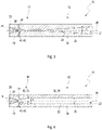
- FIG. 1 shows an external view of an embodiment of a turning tool according to the invention, consisting of a base body 12 with a clamping section 14 and a tool head 16 with a chip area 18. Several chip edges 20 are arranged on the tool head 16 in the chip area 18 on the tool head surface 44.
- the base body 12 with clamping section 14 is used for clamping in a chuck (not shown).
- the turning tool 10 can be made, for example, from chrome-vanadium steel (CV steel) or from hard metal.
- the tool head 16 is usually hardened in order to increase the mechanical resistance. This is done by changing or transforming the metal structure of the tool head 16, this being effected by heat treatment followed by rapid cooling.
- the entire tool head 16 is usually hardened here in order to achieve the desired resistance.
- the tool head 16 can be provided with a wear-resistant coating.
- FIG. 2 shows a schematic representation of a longitudinal section through an embodiment of a turning tool 10 according to the invention with a conical coolant channel 22.
- the coolant channel 22 runs from the base body 12 with clamping section 14 via the tool head 16 to the chip area 18 conically and centrally in the turning tool 10.
- the coolant outlet lines 30, 38 are connected to the coolant channel 22 via contact points 40, 42.
- the number of coolant outlet lines 30, 38 can correspond to the number of cutting edges 20 of the turning tool 10.
- the coolant outlet lines 30 , 38 are arranged in different positions 40 , 42 that are offset in the longitudinal direction of the coolant channel 22 .
- two coolant outlet lines 30 are visible at the end of the coolant channel 22 and two further coolant outlet lines 38 offset in the longitudinal direction.
- the coolant channel 22 runs centrally to the axis of rotation 28 , the cross section 24 of the coolant channel 22 decreasing towards the tool head 16 .
- the section side wall 26 of the coolant channel 22 has a constant angle ⁇ to the axis of rotation 28 over the entire length of the coolant channel 22 .
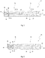
- In 3 is also a schematic representation of a longitudinal section through an embodiment of a turning tool.
- the difference to 2 lies in the configuration of the section side wall 26 of the coolant channel 22.
- the section side wall 26 of the coolant channel 22 describes a parabolic or elliptical shape. There is thus a constant angular change in the angle ⁇ between the axis of rotation 28 of the turning tool 10 and the section side wall 26 of the coolant channel 22. Consequently, the cross section 24 of the coolant channel 22 can narrow from the clamping section 14 to the tool head 16 and then increase again.
- the coolant channel 22 is arranged centrally to the axis of rotation 28 in the turning tool 10.
- the two-part coolant channel 22 consists of a constant section 32, 36 and a tapering section 32, 34.
- the cross section 24 of the coolant channel 22 is constant in the area of the constant section 32, 36 and decreases in the area of the tapering section 32, 34 to the tool head surface 44 from.
- the tapering section 32, 34 is therefore located on the tool head 16 to which the coolant outlet lines 30, 38 are attached.
- the contact points 40, 42 of the coolant outlet lines 30 are offset in the longitudinal direction in relation to the contact points 40, 42 of the coolant outlet lines 38 on the coolant channel 22.
- figure 5 shows a schematic representation of a longitudinal section through an embodiment of a turning tool 10 according to the invention with a conical coolant channel 22, consisting of two coolant channel sections 32, 34, 36 with different angles of inclination ⁇ 1, ⁇ 2.
- the coolant channel 22 is located centrally to the axis of rotation 28.
- the two coolant channel sections 32, 34, 36 have different angles of inclination ⁇ 1, ⁇ 2 between the section side wall 26 of the coolant channel 22 and the axis of rotation 28.
- the coolant channel section 32, 34 with the smaller angle ⁇ 1, where ⁇ 1 ⁇ 2, is located closer to the tool head 16.
- the coolant channel section 32, 36 with ⁇ 2, where ⁇ 2> ⁇ 1, can extend over the entire length of the clamping section 14 of the base body 12 or protrude into the tool head 16 .
- An embodiment with a coolant channel section 32, 36 with ⁇ 2 ⁇ 1 is also possible, with the coolant channel section 32, 34 with ⁇ 1> ⁇ 2 therefore being closer to the tool head 16.
- a longitudinal section through an embodiment of a turning tool 10 according to the invention with a conical coolant channel 22 is shown.
- the coolant channel 22 is conical over the entire length, as in FIG 2 .
- the coolant channel 22 is arranged centrally in the turning tool 10 and tapers in the direction of the tool head 16.
- the coolant channel 22 splits into several coolant outlet lines 30, through which the cooling and/or lubricating fluid flows into the chip area 16 to the Span edges 18 is transported.
- the chips are removed in a targeted manner by the lubricating and/or cooling fluid.
- the contact points 40, 42 of the coolant outlet lines 30, 38 with the coolant channel 22 can also be located closer to the clamping section 14 of the rotary tool 10.
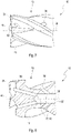
- FIG. 7 shows a perspective view of a section of the tool head 16 with coolant outlet lines 30, 38 6 .
- the coolant outlet lines 30, 38 are attached in the area of the tool head surface 44.
- a single or multiple coolant outlet line 30, 38 is located in the chip area 18 on each chip edge 20.
- the coolant outlet line 30, 38 can follow the turns of the tool head 16 of the turning tool 10.
- lubricating and/or cooling fluid can be discharged in a targeted manner and the chips that are produced when machining a material with the turning tool 10 can be discharged, so that there is no clogging by chips of the drill hole to be machined or the like.
- a longitudinal section to the view 7 indicates 8 .
- the coolant channel 22 flows into the coolant outlet lines 30, 38 at the contact points 40, 42.
- the coolant outlet lines 30, 38 extend to the tool head surface 44 on the cutting edge 20, with the offset coolant outlet lines 38 also running in this embodiment in the area of the cutting area, but on the side of the tool head end and rise to the surface there.
- the coolant outlet lines 30 are arranged at the end of the coolant channel 22 on the tool head side.
- the contact points 40, 42 of the coolant outlet lines 38 are arranged in the circumferential direction of the coolant channel 22 in a plane in the longitudinal direction. More of these offset coolant outlet lines 38 are possible in other positions in the longitudinal direction of the coolant channel 22 .
- the coolant channel 22 tapers in the direction of the tool head 16 in the area of the contact points 40 , 42 of the coolant outlet lines 30 , 38 .
- the contact points 40, 42 of the coolant outlet lines 30, 38 can be arranged spirally around the coolant channel 22, shown in FIG 9 .
- FIG. 9 shows a representation of the coolant channel 22 with coolant outlet lines 30, 38, the contact points 40, 42 are arranged in a spiral around the coolant channel 22.
- the illustration shows the pure cooling channel system 46 without showing the turning tool 10 or the tool head 16 and without showing the tool head surface 44.
- the coolant channel 22 is of conical design.
- the coolant outlet lines 30, 38 have a kink and then run parallel to the coolant channel 22 and thus parallel to the axis of rotation 28.
- the coolant outlet lines 30, 38 end in a plane on the tool head surface 44 (not shown).
- all coolant outlet lines 30, 38 are routed to the chip area 18 (not shown).
- the coolant channel outlet line 30 is the shortest and is located at the front end of the coolant channel 22.
- the other coolant outlet lines 38 are offset in the longitudinal direction relative to this coolant channel outlet line 38. Due to the spiral arrangement of the contact points 40, 42 of the coolant outlet lines 30, 38 on the coolant channel 22, a coolant outlet line 30, 38 offset in the longitudinal direction of the coolant channel 22 can be arranged between two further in the direction of the cutting area 18 Coolant outlet lines 30, 38 are. The distance and the tool material between the contact points 40, 42 is maximized by this arrangement, so that high mechanical stability and tool life can be achieved.
- the invention enables the cooling channel courses to be formed by a sintering process, with complex channel courses being able to be produced by pressing instead of drilling. This significantly reduces the manufacturing effort and time.
- the tool blanks can be manufactured with a central bore in the dry pressing process.
- the central bore is essentially conically shaped. A material saving of the solid carbide of 5 to 15%, usually at least 9%, can be achieved.
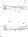
- the figs 10a and 10b each show a schematic representation of a longitudinal section through an embodiment of a turning tool 10 according to the invention with a conical coolant channel 22.
- a tool with such a coolant channel and such coolant outlet lines represents a blind hole drill or a blind hole reamer.
- the coolant channel 22 runs from the base body 12 with clamping section 14 via the tool head 16 up to the chip area 18 conically and centrally in the turning tool 10.
- several coolant outlet lines 30, 38 are arranged, which convey the cooling and/or lubricating fluid through the coolant channel 22 to the chip edges 20.
- the coolant outlet lines 30, 38 are connected to the coolant channel 22 via contact points 40, 42.
- coolant outlet lines 30 , 38 are arranged in different positions 40 , 42 that are offset in the longitudinal direction of the coolant channel 22 .
- a coolant outlet line 30 is arranged centrally and runs from the coolant channel 22 directly to the tool head surface 44, with this coolant outlet line 30 emerging centrally on the tool head surface 44.
- This coolant outlet line 30 represents an extension of the coolant channel 22 and can also be seen as a section of the coolant channel 22 .
- two further coolant outlet lines 38 offset in the longitudinal direction can be seen.
- the coolant channel 22 runs centrally to the axis of rotation 28 , the cross section 24 of the coolant channel 22 decreasing towards the tool head 16 .
- the section side wall 26 of the coolant channel 22 has a constant angle ⁇ to the axis of rotation 28 over the entire length of the coolant channel 22 .
Landscapes
- Engineering & Computer Science (AREA)
- Mechanical Engineering (AREA)
- Drilling Tools (AREA)
- Auxiliary Devices For Machine Tools (AREA)
Description
- Die Erfindung betrifft ein Drehwerkzeug für eine spanende Bearbeitung von Werkstücken, das einen Grundkörper mit einem Einspannabschnitt und einem Werkzeugkopf umfasst, der einen zumindest eine Spankante aufweisenden Spanbereich aufweist. Der Werkzeugkopf umfasst zumindest einen sich verjüngenden Kühlmittelkanal und zumindest zwei versetzt angeordnete Kühlmittelaustrittsleitungen zur Zuführung eines Kühl- und/oder Schmierfluides in den Spanbereich. Ein derartiges Drehwerkzeug gemäß dem Oberbegriff des Anspruchs 1 ist aus dem Dokument
US 2005/084351 A1 bekannt. - Des Weiteren betrifft die Erfindung ein Verfahren zur Herstellung eines diesbezüglichen Drehwerkzeugs.
- Aus dem Stand der Technik ist eine Vielzahl von Drehwerkzeugen bekannt, die einen Grundkörper mit einem Spannabschnitt und einem Werkzeugkopf aufweisen. Der Einspannabschnitt kann eine Einspannschaft oder eine besonders geformter axialer Endbereich des Drehwerkzeugs sein, der für die Aufnahme in eine spezielle Einspannvorrichtung, wie einer HSK-Spannvorrichtung, ausgebildet ist. Derartige Drehwerkzeuge können Bohr-, Reib-, Fräs- oder Polierwerkzeuge sein. In der Regel weisen derartige Drehwerkzeuge im Werkzeugkopf zumindest eine Spankante auf, durch die in einem spanabhebenden Arbeitsgang Material von einem Werkstück entfernt wird. Insbesondere bei Hochleistungsdrehwerkzeugen, beispielsweise HPC- (High Performance Cutting) oder HSC- (High Speed Cutting) Drehwerkzeugen, sind im Drehwerkzeug ein oder mehrere Kühlmittelkanäle vorgesehen, um ein Kühl- und/oder Schmierfluid in den Bereich des Werkzeugkopfs einzubringen, um den Werkzeugkopf und die umfasste Spankante zu kühlen und Materialabtrag aus dem Spanbereich abzuführen.
- Aus der
EP 0 674 560 B1 , derDE 197 19 892 A1 sowie derDE 20 2005 020 829 U1 sind Drehwerkzeuge bekannt, die einen Kühlmittelkanal aufweisen, welcher in Längsachse des Drehwerkzeugs angeordnet ist und im Bereich des Werkzeugkopfes eine oder mehrere Kühlmittelaustrittsleitungen aufweisen kann. Der Kühlmittelkanal weißt einen über die Länge konstanten Querschnitt auf und verläuft bevorzugt zentrische im Werkzeug. - Die
DE 20 2012 103 752 U1 offenbart ein Fräswerkzeug mit mindestens einem Kühlmittelkanal, wobei der Fräsdurchmesser kleiner als der Einspanndurchmesser ist. Bevorzugt umfasst das Fräswerkzeug mehrere parallel verlaufende Kühlmittelkanäle, welche in Längsrichtung des Einspannabschnitts verlaufen. Die Austrittsöffnungen der Kühlmittelkanäle liegen im Übergangsbereich zwischen Fräs- und Einspannabschnitt. Diese Ausführung eignet sich speziell für Drehwerkzeuge mit kleinem Durchmesser, d.h. für Durchmesser zwischen 0,05 mm und 4 mm. - Aus der
DE 10 2009 029 715 A1 ist ein Werkzeug zur Bearbeitung von Werkstücken bekannt, welches teils aus einem verschließfesten und teils aus einem zähen Werkstoff besteht. Das Werkzeug kann einen Kühlmittelkanal enthalten, welcher mindestens eine Kühlmittelaustrittsleitung im Bereich des Spanbereichs aufweist. Die Kühlmittelaustrittsleitungen können in verschiedenen Ebenen am Kühlmittelkanal angeordnet sein. - Die
DE 201 01 101 U1 offenbart ein Werkzeug für die Feinbearbeitung von Bohrungen, welches einen zentralen Kühlmittelkanal und radial verlaufende Kühlmittelaustrittsleitungen aufweisen kann. Ist das Werkzeug mit mehreren Schneidscheiben ausgestattet, so verlaufen in jeder Schneidscheibe Kühlmittelaustrittsleitungen, die somit in Längsrichtung zur Werkzeugachse versetzt angeordnet sind. - Die
DE 20 2006 007 085 U1 offenbart ein Drehwerkzeug mit zentral angeordnetem Kühlkanal. Der Kühlkanal weist einzeln angeordnete Kühlmittelaustrittsleitungen auf, die in Richtung Einspannabschnitt des Drehwerkzeugs geneigt sein können. Der zentral angeordnete Kühlkanal hat im Bereich dieser Kühlmittelaustrittsleitungen einen geringeren und konstanten Querschnitt als im Bereich des Einspannabschnitts, wobei der Querschnitts-Übergangsbereich als Stufe ausgebildet ist. Der Kühlkanal ist im Bereich der Kühlmittelaustrittsleitungen mit einem konstanten Querschnitt ausgebildet. - In der gattungsgemäßen
WO 03/024661 A1 - Die
DE 10 2004 055 377 A1 offenbart ein Drehwerkzeug mit einer im Innern des Drehwerkzeugs angebrachten Kühlmittel-Verteilereinrichtung. Die Verteilereinrichtung stellt ein separates Bauteil dar und teilt das Kühlmittel in Teilströme mit definiertem Volumenstrom auf. Den Schneiden des Drehwerkzeugs kann so gezielt eine bestimmte Menge an Kühlmittel zugeführt werden. Dies kann durch Bohrungen realisiert werden kann. Die Bohrungen sind in einer Ebene angeordnet. - In der
US 2007/0053755 A1 ist ein Drehwerkzeug mit einem Kühlkanal offenbar. Der Kühlkanal weist einen sich verminderten Querschnitt auf, wobei der größte Querschnitt am Einspannenden des Drehwerkzeugs angeordnet ist. - Die gattungsgemäße
DE 103 17 567 A1 lehrt ein allgemeines Verfahren zur Herstellung von Bohrwerkzeugen mit doppelhelixartig-verlaufenden Kühlkanälen. Weiterhin offenbart die gattungsgemäßeDE 36 01 385 A1 ein allgemeines Verfahren zur Herstellung von Sinterkörpern. - Die
US 3 293 727 A zeigt ein Schneidwerkzeug mit axial angeordnetem Kühlmittelkanal, wobei der Kühlmittelkanal am obersten Ende spitz zuläuft und in diesem Bereich Kühlmittelaustrittsleitungen aufweist. Die Kühlmittelaustrittsleitungen liegen in diesem spitz zulaufenden Bereich sowie in dem Bereich des Kühlkanals mit konstantem Querschnitt. - In der
EP 2 140 960 A2 wird ein Bohrwerkzeug offenbart, das einen Spänesauger zum Absaugen der beim Bohrvorgang anfallenden Späne aufweist. Dieser Spänesauger besteht aus einer Hauptleitung, die zentral im Bohrwerkzeugquerschnitt angeordnet ist und an der Spitze zulaufend ausgebildet ist, sowie mehreren Teilleitungen, die von der Hauptleitung in diesem zugespitzten Bereich abgehen. Diese Teilleitungen können in Längsrichtung des Bohrwerkzeugs versetzt in diesem zugespitzten Bereich abgehen. - Die
US 2005/084351 A1 zeigt ein Bohr- oder Fräswerkzeug mit einem Hohlraum, sodass eine materialsparende Herstellung gewährleistet werden kann. Dieser Hohlraum befindet sich teilweise im Einspannabschnitt und teilweise im Werkzeugkopf und ist im Werkzeugkopf an die Außengeometrie des Werkzeugs angepasst. Der Hohlraum weist im Bereich des Werkzeugkopfes einen nicht kreisrunden Querschnitt auf und kann dem Querschnitt der Spankanäle folgen. Der Hohlraum verläuft spiralförmig um die Rotationsachse und greift in den Werkzeugkopf ein, wobei die Form des Hohlraums durch die Form des Werkzeugs bestimmt wird. - In der
FR 2 927 556 A3 - Die
WO 98/55254 A1 - Im Bereich der Bearbeitung von Aluminium und Weichmetallwerkstoffen, die einen höheren Siliziumgehalt aufweisen, kommt es zu einem hohen Verschleiß eines Drehwerkzeugs aufgrund der Zähigkeit des zu bearbeitenden Werkstücks. Hierdurch werden insbesondere Flächen im Werkzeugkopf eines Drehwerkzeugs mechanisch wie thermisch strapaziert, wodurch diese nach längerer Benutzung des Drehwerkzeugs ausdünnen und verschleißen. Hierdurch besteht die Gefahr, dass die mechanische Stabilität des Drehwerkzeugs, die Schmierfähigkeit und die Lebensdauer eingeschränkt werden.
- Aufgabe der Erfindung ist es daher, ein Drehwerkzeug und ein Herstellverfahren vorzuschlagen, das durch eine verbesserte Kühlung einen dauerhaften Einsatz und eine hohe Bearbeitungsqualität, insbesondere bei Aluminiumwerkstoffen mit hohem Siliziumgehalt und anderen weichmetallischen und zähen Werkstoffen ermöglicht.
- Diese Aufgabe wird durch ein Drehwerkzeug und ein Herstellverfahren nach den unabhängigen Ansprüchen 1 bzw. 10 gelöst. Vorteilhafte Weiterentwicklungen der Erfindung sind Gegenstand der Unteransprüche.
- Gegenstand der Erfindung ist ein Drehwerkzeug für eine spanende Bearbeitung von Werkstücken, umfassend einen Grundkörper mit einen Einspannabschnitt sowie einem Werkzeugkopf, der einen zumindest eine Spankante aufweisenden Spanbereich umfasst, wobei der Werkzeugkopf zumindest einem Kühlmittelkanal zur Zuführung eines Kühl- und/oder Schmierfluides in den Spanbereich umfasst. Es wird vorgeschlagen, dass der Kühlmittelkanal einen sich verjüngenden Querschnitt in Richtung des Spanbereichs des Werkzeugkopfes im Werkzeugkopf aufweist und in diesem Bereich zumindest zwei von Kontaktstellen des Kühlmittelkanals in Richtung Werkzeugkopfoberfläche abzweigende Kühlmittelaustrittsleitungen im Bereich des Werkzeugkopfes angeordnet sind, wobei die mindestens zwei Kühlmittelaustrittsleitungen an in axialer Längsrichtung des Kühlmittelkanals versetzten Positionen angeordnet sind. Der Kühlmittelkanal ist über die komplette Länge des Drehwerkzeugs verjüngt ausgebildet.
- Durch die in Längsrichtung des Kühlmittelkanals versetzt angeordneten Kühlmittelaustrittsleitungen wird Schmier- und/oder Kühlfluid kontinuierlich aus dem Kühlmittelkanal abgeführt. Bei mehreren versetzt angeordneten Kühlmittelaustrittsleitungen sinkt somit in Abhängigkeit der Menge des durch die jeweilige Kühlmittelaustrittsleitung abgeführten Schmier- und/oder Kühlfluides der statische Druck im Kühlmittelkanal. Durch den Druckabfall verringert sich ebenso die Fließgeschwindigkeit und somit die Durchflussmenge. Die am nahsten am Spanbereich des Werkzeugkopfes, d.h. an der Werkzeugspitze, angeordnete Kühlmittelaustrittsleitung erhält somit am wenigsten Schmier- und/oder Kühlfluid, wobei an die ser Stelle die Temperaturerhöhung während der Bearbeitung mit dem Drehwerkzeug am größten ist. Um dies zu unterbinden, ist erfindungsgemäß angestrebt die Durchflussmenge durch den Kühlmittelkanal zumindest in dem Bereich, in dem Kühlmittelaustrittsleitungen angebracht sind, konstant zu halten, obwohl Schmier- und/oder Kühlfluid durch die Kühlmittelaustrittsleitungen abgeführt wird.
- Durch einen sich verjüngenden Querschnitt des Kühlmittelkanals in Richtung des Spanbereichs des Werkzeugkopfs wird der Druck des Schmier- und/oder Kühlfluides im Bereich des Werkzeugkopfes kontinuierlich erhöht und somit in diesem Bereich die Durchflussmenge im Kühlmittelkanal kontinuierlich gesteigert werden. Durch die Abführung von Schmier- oder Kühlfluid durch die Kühlmittelaustrittsleitungen kann diese Steigerung der Durchflussmenge wieder ausgeglichen werden. Die Querschnittsänderung des Kühlmittelkanals kann exakt an die Menge des durch die Kühlmittelaustrittsleitungen abgeführten Schmier- und/oder Kühlfluides angepasst werden, sodass der Druck und damit die Durchflussmenge im Kühlmittelkanal konstant gehalten werden kann. In alle Kühlmittelaustrittsleitungen kann demzufolge die gleiche Menge an Schmier- und/oder Kühlfluid mit gleichem Druck und damit gleicher Durchflussmenge eingespeist werden.
- In einem weiteren Aspekt kann Gewicht und Material bei einer erfindungsgemäßen Ausführung eines Drehwerkzeuges eingespart werden.
- Bei einer Ausführungsform mit verjüngtem Querschnitt des Kühlmittelkanals in Richtung des Werkstoffkopfes ist im Einspannabschnitt im Vergleich zum Werkzeugkopf weniger Material vorhanden. Im Betrieb erreicht das Drehwerkzeug im Bereich des Werkzeugkopfes eine höhere Temperatur als im Bereich des Einspannabschnittes.
- Aus einem großen Temperaturgradienten innerhalb des Drehwerkzeuges resultieren höhere mechanische Verspannungen und ein geometrischer Verzug. Durch eine Verringerung dieses Temperaturgradienten können Spannungen reduziert und ein Verzug des Drehwerkzeuges minimiert werden. Ist die Materialverteilung im Drehwerkzeug umgekehrt proportional zur Temperaturverteilung, wie in der vorliegenden Erfindung angestrebt, so kann der Temperaturgradient innerhalb des Drehwerkzeuges minimiert werden.
- Der Kühlmittelkanals kann beispielsweise einen kreisförmigen, teilkreisförmigen, elliptischen, trapezförmigen, dreiecksförmigen, quadratischen oder rechteckigen Querschnitt aufweisen. Hierbei kann sich die Querschnittsform auch über die Länge des Kühlkanals in ihrer grundlegenden Form graduell ändern oder Querschnittssprünge aufweisen.
- In einer vorteilhaften Ausführungsform können die Kühlmittelaustrittsleitungen in Umfangsrichtung des Kühlmittelkanals versetzt angeordnet sein. Hierbei können die Kontaktstellen der Kühlmittelaustrittsleitungen in radialer Richtung oder in Längsrichtung des Kühlmittelkanals versetzt hintereinander angeordnet sein. Ebenso können beide Anordnungen kombiniert werden. Bei in radialer Richtung versetzter Anordnung können die Kontaktstellen der Kühlmittelaustrittsleitungen Zickzack-förmig um den Umfang des Kühlmittelkanals platziert werden. Durch eine radiale Versetzung können alle Umfangsbereiche des Werkzeugkopfs gleichmäßig gekühlt werden.
- In einer weiteren vorteilhaften Ausführungsform können die Kontaktstellen der Kühlmittelaustrittsleitungen mit dem Kühlmittelkanal spiralartig um den Kühlmittelkanal angeordnet sein. Hierbei kann die Spiralform auch mehrmals den Umfang des Kühlmittelkanals umlaufen. Die Kontaktstellen der Kühlmittelaustrittsleitungen mit dem Kühlmittelkanal können somit spiralartig in Umfangsrichtung um den Kühlmittelkanal und hintereinander versetzt in Längsrichtung des Kühlmittelkanals angeordnet sein. Hierbei können alle Kühlmittelaustrittsleitungen bis zur gleichen Ebene an der Werkzeugkopfoberfläche geführt werden oder stufenartig in versetzten Ebenen aus dem Werkzeugkopf an die Oberfläche geführt werden. Es wird ein maximal großer Abstand der Austrittsleitungen ermöglicht, so dass eine Schwächung der Werkzeugwand verringert wird.
- Es bietet sich vorzugsweise an, dass der Kühlmittelkanal im Bereich des Grundkörpers einen größeren Querschnitt aufweist als im Bereich des Werkzeugkopfes. Durch einen sich verjüngenden Querschnitt des Kühlmittelkanals in Richtung des Spanbereichs des Werkzeugkopfes in zumindest dem Bereich, in dem Kühlmittelaustrittsleitungen abgehen, wird der Druck des Schmier- und/oder Kühlfluides im Bereich des Werkzeugkopfes kontinuierlich erhöht. Im Bereich des Kühlmittelkanals kann somit der Druck des Schmier- und/oder Kühlfluides erhöht und die Durchflussmenge kontinuierlich gesteigert werden, so dass eine verbesserte Kühlwirkung des Werkzeugkopfes gewährleistet ist.
- In einer weiteren Ausführungsform kann der komplette Verlauf des Kühlmittelkanals eine elliptische und/oder parabolische Form ausbilden. Der Kühlmittelkanal kann hierbei vom Einspannabschnitt über den Werkzeugkopf und wieder zurück zum Einspannabschnitt verlaufen. Der Verlauf des Kühlmittelkanals kann hierbei einer Ellipsen- und/oder Parabelform folgen. Ebenso können zwei oder mehrere Kühlmittelkanäle vom Einspannabschnitt in den Werkzeugkopf und wieder zurück zum Einspannabschnitt verlaufen. Die sich daraus insgesamt ausbildenden Kühlmittelkanäle können sich an einem Punkt im Bereich des Werkzeugkopfes schneiden und von diesem Schnittpunkt in mehrere zueinander abgewinkelte liegenden Orientierungen in Richtung des Einspannabschnittes verlaufen.
- In einer vorteilhaften Ausführungsform kann der Kühlmittelkanal zumindest zwei Abschnitte, insbesondere drei Abschnitte umfassen, welche jeweils einen unterschiedlichen Neigungswinkel α1, α2 oder Krümmungsverlauf zwischen den Abschnittsseitenwänden des Kühlmittelkanals und der Rotationsachse des Drehwerkzeugs aufweisen. Die Drucksteigerung des Kühl- und/oder Schmierfluides innerhalb des Drehwerkzeugs kann somit an spezielle Anforderungen individuell angepasst werden. Im Falle von α = 90° besteht der Abschnitt des Kühlmittelkanals lediglich aus dem Querschnittssprung von einem Abschnitt mit kleinerem Querschnitt zu einem Abschnitt mit größerem Querschnitt oder umgekehrt.
- Gemäß der Erfindung ist der Kühlmittelkanal über die komplette Länge des Drehwerkzeugs verjüngt ausgebildet. Die Druckverteilung des Kühl- und/oder Schmierfluides wird somit kontinuierlich vom Einspannabschnitt über den Werkzeugkopf bis zur Werkzeugkopfoberfläche gesteigert.
- Der kleinere Querschnitt des sich so einstellende konischen Kühlmittelkanals ist im Bereich des Werkzeugkopfes angeordnet.
- In einer bevorzugten Ausführungsform kann der Kühlmittelkanal zentrisch im Grundkörper verlaufen. Für das Drehwerkzeug kann so eine optimale Drehdynamik erreicht werden und das Material des Einspannabschnittes kann somit optimal gekühlt werden. Der Kühlmittelkanal im Grundkörper kann sich im Bereich des Werkzeugkopfes auch in mehrere einzelne Kühlmittelaustrittsleitungen aufspalten. Diese können beispielsweise den Verwindungen des Werkzeugkopfes folgen. Durch die Kühlmittelaustrittsleitungen kann jede Spankante optimal gekühlt werden. Die anfallenden Späne werden ebenso durch den Austritt des Schmier- und/oder Kühlfluides an der Werkzeugkopfoberfläche optimal abgeleitet.
- In einer bevorzugten Ausführungsform kann der Kühlmittelkanal zentrisch im Werkzeugkopf verlaufen. Hierbei kann das Schmier- und/oder Kühlfluid auch über eine Mehrzahl von Kühlmittelkanälen im Grundkörper in den Kühlmittelkanal im Werkzeugkopf eingespeist werden. Für das Drehwerkzeug kann so eine optimale Drehdynamik erreicht werden und das Material des Werkzeugkopfes kann somit optimal gekühlt werden. Der Kühlmittelkanal im Werkzeugkopf kann sich im Bereich des Einspannabschnittes auch in mehrere einzelne Kühlmittelkanäle aufspalten, welche beispielsweise parallel durch den Einspannabschnitt verlaufen. Im Bereich des Werkzeugkopfes kann sich der zentrisch angeordnete Kühlmittelkanal in mehrere Kühlmittelaustrittsleitungen aufspalten.
- In einer bevorzugten Ausführungsform kann der Kühlmittelkanal im Werkzeugkopf im Bereich des Spanbereichs zumindest eine, bevorzugt zumindest zwei Kühlmittelaustrittsleitungen umfassen. Die Kühlmittelaustrittsleitungen können geradlinig, abgewinkelt, gebogen oder verdreht ausgebildet sein, und können den Verwindungen des Drehwerkzeugs folgen. Vorteilhafterweise ist der Kühlmittelkanal im Bereich der Kontaktstellen der Kühlmittelaustrittsleitungen mit dem Kühlmittelkanal verjüngt ausgebildet. Durch die Abführung von Schmier- und/oder Kühlfluid durch die Kühlmittelaustrittsleitungen kann die Steigerung der Durchflussmenge wieder ausgeglichen werden. Die Querschnittsänderung des Kühlkanals kann exakt an die Menge des durch die Kühlmittelaustrittsleitungen abgeführten Schmier- und/oder Kühlfluides angepasst werden, so dass der Druck und damit die Durchflussmenge im Kühlkanal konstant gehalten werden können. In alle Kühlmittelaustrittsleitungen kann demzufolge die gleiche Menge an Schmier- und/oder Kühlfluid mit gleichem Druck und damit gleicher Durchflussmenge eingespeist werden wie im Kühlmittelkanal selbst.
- In einer vorteilhaften Ausführungsform kann die Anzahl der Kühlmittelaustrittsleitungen der Anzahl der Spankanten des Werkzeugkopfes entsprechen. Auf diese Weise kann jede Spankante des Werkzeugkopfes gezielt einzeln gekühlt werden. Ebenso können die Späne an jeder Spankante durch das Kühl- und/oder Schmierfluid gezielt abgeführt werden.
- Gegenstand der Erfindung ist weiterhin ein Verfahren zur Herstellung eines erfindungsgemäßen Drehwerkzeugs. Das Verfahren ist dadurch gekennzeichnet, dass die Herstellung des Rohlings des Drehwerkzeugs durch ein Sinterverfahren, bei dem der Rohling durch Pressen unter hohem Druck eines feinkörnigen Metallpulvers, erfolgt, bei dem der Kühlmittelkanal des Drehwerkzeugs integral im Sinterverfahren mit ausgebildet wird. Mit diesem Verfahren kann jede beliebige Form und Ausführung des Kühlmittelkanals problemlos hergestellt werden. Hierzu wird eine Positivform des Kühlkanals als innerer Kern des Rohlings eingesetzt.
- In einer weiteren Ausführungsform des Verfahrens zur Herstellung des erfindungsgemäßen Drehwerkzeugs können bei der Herstellung des Rohlings die Kühlmittelaustrittsleitungen des Drehwerkzeugs integral im Sinterverfahren mit ausgebildet werden. Ein innerer Positivkern des Kühlkanals kann vorzugsweise mehrteilige Kühlkanalaustrittsleitungen umfassen, die nach dem Sinterverfahren aus dem Rohling entnommen werden können. Der bzw. die Kerne der Kühlkanalaustrittsleitungen können vorzugsweise in den Kern des Kühlkanals eingesteckt werden. Das komplette Kühlmittelkanalsystem kann somit während des Sinterverfahrens hergestellt werden.
- Die im Zusammenhang mit der erfindungsgemäßen Vorrichtung und dem erfindungsgemäßen innengekühlten Drehwerkzeug und deren jeweiligen vorteilhaften Ausführungsformen und Ausgestaltungen aufgezeigten Vorteile und Merkmale gelten für das erfindungsgemäße Verfahren und dessen vorteilhafte Ausführungsformen entsprechend und umgekehrt.
- Weitere Vorteile ergeben sich aus der vorliegenden Zeichnungen und Zeichnungsbeschreibungen. In den Zeichnungen sind Ausführungsbeispiele der Erfindung dargestellt. Die Zeichnung, die Beschreibung und die Ansprüche enthalten zahlreiche Merkmale in Kombination.
- Es zeigt:
- Fig. 1
- eine Außenansicht eines Drehwerkzeugs mit einem Grundkörper und einem Werkzeugkopf eines Ausführungsbeispiels eines erfindungsgemäßen Drehwerkzeugs mit Kühlmittelkanal;
- Fig. 2
- eine schematische Darstellung eines Längsschnittes durch ein Ausführung eines erfindungsgemäßen Drehwerkzeugs mit konischen Kühlmittelkanal;
- Fig. 3
- eine schematische Darstellung eines Längsschnittes durch eine Ausführung eines Drehwerkzeugs mit elliptischem Kühlmittelkanal, das nicht unter den Gegenstand des Schutzbegehrens fällt;
- Fig. 4
- eine schematische Darstellung eines Längsschnittes durch eine Ausführung eines Drehwerkzeugs mit zweigeteiltem Kühlmittelkanal, das nicht unter den Gegenstand des Schutzbegehrens fällt, umfassend einen sich verjüngenden und einen konstanten Querschnitt des Kühlmittelkanals;
- Fig. 5
- eine schematische Darstellung eines Längsschnittes durch ein Ausführung eines erfindungsgemäßen Drehwerkzeugs mit konischem Kühlmittelkanal mit zwei Kühlmittelkanal-Abschnitten mit unterschiedlichen Neigungswinkeln α1 und α2;
- Fig. 6
- eine Darstellung eines Längsschnittes durch eine Ausführung eines erfindungsgemäßen Drehwerkzeugs mit konischem Kühlmittelkanal;
- Fig. 7
- eine perspektivische Darstellung eines Ausschnittes eines Werkzeugkopfes nach
Fig. 6 mit Kühlmittelaustrittsleitungen; - Fig. 8
- eine Darstellung eines Längsschnittes durch einen Werkzeugkopf nach
Fig. 7 mit Kühlmittelkanal und Kühlmittelaustrittsleitungen; - Fig. 9
- eine perspektivische Darstellung eines Kühlmittelkanals mit spiralförmig angeordneten Kühlmittelaustrittsleitungen, Darstellung ohne Drehwerkzeug.
- Fig. 10
- eine Darstellung eines Längsschnittes durch einen Werkzeugkopf mit Kühlmittelkanal und Kühlmittelaustrittsleitungen;
- In den Figuren sind gleiche oder gleichartige Komponenten mit gleichen Bezugszeichen beziffert.
-
Fig. 1 zeigt eine Außenansicht einer erfindungsgemäßen Ausführung eines Drehwerkzeugs, bestehend aus einem Grundkörper 12 mit Einspannabschnitt 14 und einem Werkzeugkopf 16 mit Spanbereich 18. Am Werkzeugkopf 16 im Spanbereich 18 sind an der Werkzeugkopfoberfläche 44 mehrere Spankanten 20 angeordnet. Der Grundkörper 12 mit Einspannabschnitt 14 dient zur Einspannung in einem Spannfutter (nicht gezeigt). Das Drehwerkzeug 10 kann beispielsweise aus einem Chrom-Vanadium-Stahl (CV-Stahl) oder aus Hartmetall hergestellt werden. Zur Erhöhung der Lebensdauer und der Funktionseigenschaften eines Drehwerkzeugs wird in der Regel der Werkzeugkopf 16 gehärtet, um die mechanische Widerstandsfähigkeit zu erhöhen. Dies erfolgt durch eine Änderung oder Umwandlung des Metallgefüges des Werkzeugkopfes 16, wobei dies durch eine Wärmebehandlung mit einer anschließenden schnellen Abkühlung bewirkt wird. Üblicherweise wird hierbei der gesamte Werkzeugkopf 16 gehärtet, um die gewünschte Widerstandsfähigkeit zu erreichen. Ebenso kann der Werkzeugkopf 16 mit einer verschleißfesten Beschichtung versehen werden. -
Fig. 2 zeigt eine schematische Darstellung eines Längsschnittes durch eine Ausführung eines erfindungsgemäßen Drehwerkzeugs 10 mit konischem Kühlmittelkanal 22. Der Kühlmittelkanal 22 verläuft vom Grundkörper 12 mit Einspannabschnitt 14 über den Werkzeugkopf 16 bis zum Spanbereich 18 konisch und zentrisch im Drehwerkzeug 10. Im Bereich des Spanbereichs 18 sind mehrere Kühlmittelaustrittsleitungen 30, 38 angeordnet, welche das Kühl- und/oder Schmierfluid durch den Kühlmittelkanal 22 bis zu den Spankanten 20 befördern. Die Kühlmittelaustrittsleitungen 30, 38 sind über Kontaktstellen 40, 42 mit dem Kühlmittelkanal 22 verbunden. Die Anzahl der Kühlmittelaustrittsleitungen 30, 38 kann der Anzahl der Spankanten 20 des Drehwerkzeugs 10 entsprechen. Hierbei sind die Kühlmittelaustrittsleitungen 30, 38 in unterschiedlichen, in Längsrichtung des Kühlmittelkanals 22 versetzten Positionen 40, 42 angeordnet. Im dargestellten schematischen Längsschnitt sind zwei Kühlmittelaustrittsleitungen 30 am Ende des Kühlmittelkanals 22 und zwei weitere Kühlmittelaustrittsleitungen 38 in Längsrichtung versetzt sichtbar. Der Kühlmittelkanal 22 verläuft zentrisch zur Rotationsachse 28, wobei der Querschnitt 24 des Kühlmittelkanals 22 zum Werkzeugkopf 16 hin abnimmt. Die Abschnittsseitenwand 26 des Kühlmittelkanals 22 weist über die gesamte Länge des Kühlmittelkanals 22 einen konstanten Winkel α zur Rotationsachse 28 auf. - In
Fig. 3 ist ebenfalls eine schematische Darstellung eines Längsschnittes durch eine Ausführungsform eines Drehwerkzeugs dargestellt. Der Unterschied zurFig. 2 liegt in der Ausgestaltung der Abschnittsseitenwand 26 des Kühlmittelkanals 22. In dieser Ausführungsform beschreibt die Abschnittsseitenwand 26 des Kühlmittelkanals 22 eine Parabel- oder Ellipsenform. Somit besteht eine stetige Winkeländerung des Winkels α zwischen der Rotationsachse 28 des Drehwerkzeugs 10 und der Abschnittsseitenwand 26 des Kühlmittelkanals 22. Folglich kann sich der Querschnitt 24 des Kühlmittelkanals 22 vom Einspannabschnitt 14 bis zum Werkzeugkopf 16 verjüngen und anschließend wieder vergrößern. -
Fig. 4 zeigt eine schematische Darstellung eines Längsschnittes durch ein Drehwerkzeug 10 mit zweigeteiltem Kühlmittelkanal 22. Der Kühlmittelkanal 22 ist zentrisch zur Rotationsachse 28 im Drehwerkzeug 10 angeordnet. Der zweigeteilte Kühlmittelkanal 22 besteht aus einem konstanten Abschnitt 32, 36 und einen sich verjüngenden Abschnitt 32, 34. Der Querschnitt 24 des Kühlmittelkanals 22 ist im Bereich des konstanten Abschnittes 32, 36 konstant, und nimmt im Bereich des sich verjüngenden Abschnitts 32, 34 hin zur Werkzeugkopfoberfläche 44 ab. Der sich verjüngende Abschnitt 32, 34 befindet sich demnach am Werkzeugkopf 16, an welchem die Kühlmittelaustrittsleitungen 30, 38 angebracht sind. Die Kontaktstellen 40, 42 der Kühlmittelaustrittsleitungen 30 liegen in Bezug zu den Kontaktstellen 40, 42 der Kühlmittelaustrittsleitungen 38 in Längsrichtung versetzt auf dem Kühlmittelkanal 22. -
Fig. 5 zeigt eine schematische Darstellung eines Längsschnittes durch eine Ausführungsform eines erfindungsgemäßen Drehwerkzeugs 10 mit konischem Kühlmittelkanal 22, bestehend aus zwei Kühlmittelkanal-Abschnitten 32, 34, 36 mit unterschiedlichen Neigungswinkeln α1, α2. Der Kühlmittelkanal 22 befindet sich zentrisch zur Rotationsachse 28. Die beiden Kühlmittelkanal-Abschnitte 32, 34, 36 haben unterschiedliche Neigungswinkel α1, α2 zwischen der Abschnittsseitenwand 26 des Kühlmittelkanals 22 und der Rotationsachse 28. Hierbei befindet sich der Kühlmittelkanal-Abschnitt 32, 34 mit dem kleineren Winkel α1, wobei α1 < α2, näher am Werkzeugkopf 16. Der Kühlmittelkanal-Abschnitt 32, 36 mit α2, wobei α2 > α1, kann sich über die komplette Länge des Einspannabschnitts 14 des Grundkörpers 12 erstrecken oder auch in den Werkzeugkopf 16 hineinragen. Ebenso ist eine Ausführungsform mit einem Kühlmittelkanal-Abschnitt 32, 36 mit α2 < α1 möglich, wobei demnach der Kühlmittelkanal-Abschnitt 32, 34 mit α1 > α2 näher am Werkzeugkopf 16 liegt. - In
Fig. 6 ist ein Längsschnitt durch eine Ausführung eines erfindungsgemäßen Drehwerkzeugs 10 mit konischem Kühlmittelkanal 22 dargestellt. In dieser Ausführungsform ist der Kühlmittelkanal 22 über die komplette Länge konisch ausgebildet, wie inFig. 2 . Der Kühlmittelkanal 22 ist zentrisch im Drehwerkzeug 10 angeordnet und verjüngt sich in Richtung des Werkzeugkopfes 16. Im Bereich des Werkzeugkopfes 16 spaltet sich der Kühlmittelkanal 22 in mehrere Kühlmittelaustrittsleitungen 30 auf, durch welche das Kühl- und/oder Schmierfluid bis in den Spanbereich 16 zu den Spankanten 18 transportiert wird. In einem weiteren Aspekt werden die Späne gezielt durch das Schmier- und/oder Kühlfluid abgeführt. Die Kontaktstellen 40, 42 der Kühlmittelaustrittsleitungen 30, 38 mit dem Kühlmittelkanal 22 können sich auch näher am Einspannabschnitt 14 des Drehwerkzeugs 10 befinden. -
Fig. 7 zeigt eine perspektivische Darstellung eines Ausschnittes des Werkzeugkopfes 16 mit Kühlmittelaustrittsleitungen 30, 38 nachFig. 6 . Die Kühlmittelaustrittsleitungen 30, 38 sind im Bereich der Werkzeugkopfoberfläche 44 angebracht. Hierbei befindet sich im Spanbereich 18 an jeder Spankante 20 eine einzelne oder mehrfache Kühlmittelaustrittsleitung 30, 38. Die Kühlmittelaustrittsleitung 30, 38 kann den Windungen des Werkzeugkopfes 16 des Drehwerkzeugs 10 folgen. Durch die Kühlmittelaustrittsleitungen 30, 38 kann gezielt Schmier- und/oder Kühlfluid abgeführt werden und die Späne, welche bei der Bearbeitung eines Materials mit dem Drehwerkzeug 10 entstehen, abgeführt werden, sodass kein Verstopfen durch Späne des zu bearbeitenden Bohrloches oder ähnlichem entsteht. - Einen Längsschnitt zu der Ansicht aus
Fig. 7 zeigtFig. 8 . Der Kühlmittelkanal 22 mündet an den Kontaktstellen 40, 42 in die Kühlmittelaustrittsleitungen 30, 38. Die Kühlmittelaustrittsleitungen 30, 38 erstrecken sich bis zur Werkzeugkopfoberfläche 44 an der Spankante 20, wobei auch die versetzt angeordneten Kühlmittelaustrittsleitungen 38 in dieser Ausführungsform im Bereich des Spanbereichs verlaufen, jedoch seitlich am Werkzeugkopf enden und dort an die Oberfläche treten. Die Kühlmittelaustrittsleitungen 30 sind am werkzeugkopfseitigen Ende des Kühlmittelkanals 22 angeordnet. Die Kontaktstellen 40, 42 der Kühlmittelaustrittsleitungen 38 sind in dieser Ausführungsform in Umfangsrichtung des Kühlmittelkanals 22 in einer Ebene in Längsrichtung angeordnet. Weitere dieser versetzt angeordneter Kühlmittelaustrittsleitungen 38 sind auf weiteren Positionen in Längsrichtung des Kühlmittelkanals 22 möglich. Der Kühlmittelkanal 22 ist im Bereich der Kontaktstellen 40, 42 der Kühlmittelaustrittsleitungen 30, 38 verjüngt in Richtung des Werkzeugkopfes 16 ausgebildet. Ebenso können die Kontaktstellen 40, 42 der Kühlmittelaustrittsleitungen 30, 38 spiralförmig um den Kühlmittelkanal 22 angeordnet sein, gezeigt inFig. 9 . -
Fig. 9 zeigt eine Darstellung des Kühlmittelkanals 22 mit Kühlmittelaustrittsleitungen 30, 38, deren Kontaktstellen 40, 42 spiralförmig um den Kühlmittelkanal 22 angeordnet sind. Die Darstellung zeigt das reine Kühlkanalsystem 46 ohne Ansicht des Drehwerkzeugs 10 bzw. des Werkzeugkopfes 16 und ohne Darstellung der Werkzeugkopfoberfläche 44. Der Kühlmittelkanal 22 ist konisch ausgebildet. In der dargestellten Ausführungsform weisen die Kühlmittelaustrittsleitungen 30, 38 einen Knick auf und verlaufen anschließend parallel zum Kühlmittelkanal 22 und damit parallel zur Rotationsachse 28. Die Kühlmittelaustrittsleitungen 30, 38 enden in einer Ebene an der Werkzeugkopfoberfläche 44 (nicht dargestellt). Im Gegensatz zu den Kühlmittelaustrittsleitungen 30, 38 aus beispielsweiseFig. 7 oder Fig. 8 werden demnach alle Kühlmittelaustrittleitungen 30, 38 bis an den Spanbereich 18 (nicht dargestellt) geführt. Die Kühlmittelkanalaustrittsleitung 30 ist am kürzesten und liegt am vorderen Ender des Kühlmittelkanals 22. Die weiteren Kühlmittelaustrittsleitungen 38 sind in Längsrichtung versetzt zu dieser Kühlmittelkanalaustrittsleitung 38 angeordnet. Durch die spiralförmige Anordnung der Kontaktstellen 40, 42 der Kühlmittelaustrittsleitungen 30, 38 auf dem Kühlmittelkanal 22 kann eine in Längsrichtung des Kühlmittelkanals 22 versetzt angeordnete Kühlmittelaustrittsleitung 30, 38 zwischen zwei weiter in Richtung Spanbereich 18 angeordneten Kühlmittelaustrittsleitungen 30, 38 liegen. Der Abstand und das Werkzeugmaterial zwischen den Kontaktstellen 40, 42 wird durch diese Anordnung maximiert, so dass eine hohe mechanische Stabilität und Standzeit des Werkzeugs erreicht werden kann. - Die Erfindung ermöglicht die Ausbildung der Kühlkanalverläufe durch ein Sinterverfahren, wobei komplexe Kanalverläufe durch Pressen, anstelle von Bohren herstellbar sind. Hierdurch wird der Herstellaufwand und -zeit deutlich verringert. Die Werkzeug-Rohlinge können mit einer Zentralbohrung im Trockenpressverfahren hergestellt werden. Die Zentralbohrung ist im Wesentlichen konisch ausgeformt. Eine Materialeinsparung des Vollhartmetalls von 5 bis 15%, in der Regel von zumindest 9% kann erreicht werden.
- Die
Figs. 10a und 10b zeigen jeweils eine schematische Darstellung eines Längsschnittes durch eine Ausführung eines erfindungsgemäßen Drehwerkzeugs 10 mit konischem Kühlmittelkanal 22. Ein Werkzeug mit einem derartigen Kühlmittelkanal und derartigen Kühlmittelaustrittsleitungen stellt einen Sacklochbohrer oder eine Sacklochreibahle dar. Der Kühlmittelkanal 22 verläuft vom Grundkörper 12 mit Einspannabschnitt 14 über den Werkzeugkopf 16 bis zum Spanbereich 18 konisch und zentrisch im Drehwerkzeug 10. Im Bereich des Spanbereichs 18 sind mehrere Kühlmittelaustrittsleitungen 30, 38 angeordnet, welche das Kühl- und/oder Schmierfluid durch den Kühlmittelkanal 22 bis zu den Spankanten 20 befördern. Die Kühlmittelaustrittsleitungen 30, 38 sind über Kontaktstellen 40, 42 mit dem Kühlmittelkanal 22 verbunden. Teilweise sind die Kühlmittelaustrittsleitungen 30, 38 in unterschiedlichen, in Längsrichtung des Kühlmittelkanals 22 versetzten Positionen 40, 42 angeordnet. Eine Kühlmittelaustrittsleitung 30 ist zentrisch angeordnet und verläuft vom Kühlmittelkanal 22 direkt zur Werkzeugkopfoberfläche 44, wobei diese Kühlmittelaustrittsleitung 30 zentrisch an der Werkzeugkopfoberfläche 44 hervortritt. Diese Kühlmittelaustrittsleitung 30 stellt eine Verlängerung des Kühlmittelkanals 22 dar und kann auch als Abschnitt des Kühlmittelkanals 22 gesehen werden. Im dargestellten schematischen Längsschnitt sind zwei weitere Kühlmittelaustrittsleitungen 38 in Längsrichtung versetzt sichtbar. Der Kühlmittelkanal 22 verläuft zentrisch zur Rotationsachse 28, wobei der Querschnitt 24 des Kühlmittelkanals 22 zum Werkzeugkopf 16 hin abnimmt. Die Abschnittsseitenwand 26 des Kühlmittelkanals 22 weist über die gesamte Länge des Kühlmittelkanals 22 einen konstanten Winkel α zur Rotationsachse 28 auf. -
- 10
- Drehwerkzeug
- 12
- Grundkörper
- 14
- Einspannabschnitt
- 16
- Werkzeugkopf
- 18
- Spanbereich
- 20
- Spankante
- 22
- Kühlmittelkanal
- 24
- Querschnitt
- 26
- Abschnittsseitenwand des Kühlmittelkanals
- 28
- Rotationsachse
- 30
- Kühlmittelaustrittsleitung
- 32
- Kühlmittelkanal Abschnitt
- 34
- Kühlmittelkanal Abschnitt 1
- 36
- Kühlmittelkanal Abschnitt 2
- 38
- versetzte Kühlmittelaustrittsleitung
- 40
- Position der Kühlmittelaustrittsleitung auf dem Kühlkanal
- 42
- Kontaktstelle Kühlmittelaustrittsleitung-Kühlkanal
- 44
- Werkzeugkopfoberfläche
- 46
- Kühlkanalsystem
Claims (11)
- Drehwerkzeug (10) für eine spanende Bearbeitung von Werkstücken, umfassend einen Grundkörper (12) mit einen Einspannabschnitt (14) sowie einem Werkzeugkopf (16), der einen zumindest eine Spankante (20) aufweisenden Spanbereich (18) umfasst, wobei der Werkzeugkopf (16) zumindest einem Kühlmittelkanal (22) zur Zuführung eines Kühl- und/oder Schmierfluides in den Spanbereich (18) umfasst, dadurch gekennzeichnet, dass der Kühlmittelkanal (22) einen sich verjüngenden Querschnitt (24) in Richtung des Werkzeugkopfes (16) aufweist und in diesem Bereich zumindest zwei von Kontaktstellen (40, 42) des Kühlmittelkanals (22) in Richtung Werkzeugkopfoberfläche (44) abzweigende Kühlmittelaustrittsleitungen (30, 38) im Bereich des Werkzeugkopfes (16) angeordnet sind, wobei die mindestens zwei Kühlmittelaustrittsleitungen (30, 38) an in axialer Längsrichtung des Kühlmittelkanals (22) versetzten Positionen (40) angeordnet sind, wobei der Kühlmittelkanal (22) über die komplette Länge des Drehwerkzeugs (10) verjüngt ausgebildet ist.
- Drehwerkzeug (10) nach Anspruch 1, dadurch gekennzeichnet, dass die Kühlmittelaustrittsleitungen (30, 38) in Umfangsrichtung des Kühlmittelkanals (22) versetzt angeordnet sind.
- Drehwerkzeug (10) nach Anspruch 1 und 2, dadurch gekennzeichnet, dass die Kontaktstellen (40, 42) der Kühlmittelaustrittsleitungen (30, 38) mit dem Kühlmittelkanal (22) spiralartig um den Kühlmittelkanal (22) angeordnet sind.
- Drehwerkzeug (10) nach einem der vorgenannten Ansprüche, dadurch gekennzeichnet, dass der Kühlmittelkanal (22) im Bereich des Grundkörpers (12) einen größeren Querschnitt (24) aufweist als im Bereich des Werkzeugkopfes (16).
- Drehwerkzeug (10) nach einem der vorgenannten Ansprüche, dadurch gekennzeichnet, dass der Kühlmittelkanal (22) zumindest abschnittsweise konisch und/oder elliptisch und/oder parabolisch ausgebildet ist.
- Drehwerkzeug (10) nach einem der vorgenannten Ansprüche, dadurch gekennzeichnet, dass der Kühlmittelkanal (22) zumindest zwei Abschnitte (32, 34, 36), insbesondere drei Abschnitte (32, 34, 36) umfasst, welche jeweils einen unterschiedlichen Neigungswinkel a1, a2 zwischen den Abschnittsseitenwänden (26) des Kühlmittelkanals (22) und der Rotationsachse (28) des Drehwerkzeugs (10) aufweisen.
- Drehwerkzeug (10) nach einem der vorgenannten Ansprüche, dadurch gekennzeichnet, dass der Kühlmittelkanal (22) zentrisch im Grundkörper (12) verläuft.
- Drehwerkzeug (10) nach einem der vorgenannten Ansprüche, dadurch gekennzeichnet, dass der Kühlmittelkanal (22) zentrisch im Werkzeugkopf (16) verläuft.
- Drehwerkzeug (10) nach einem der vorgenannten Ansprüche, dadurch gekennzeichnet, dass die Anzahl der Kühlmittelaustrittsleitungen (30) der Anzahl der Spankanten (20) des Werkzeugkopfes (16) entspricht.
- Verfahren zur Herstellung eines Drehwerkzeugs (10) nach einem der vorgenannten Ansprüche, dadurch gekennzeichnet, dass die Herstellung des Rohlings des Drehwerkzeugs (10) durch ein Sinterverfahren erfolgt, bei dem der Kühlmittelkanal (22) des Drehwerkzeugs (10) integral im Sinterverfahren mit ausgebildet wird.
- Verfahren zur Herstellung eines Drehwerkzeugs (10) nach Anspruch 10, dadurch gekennzeichnet, dass bei der Herstellung des Rohlings die Kühlmittelaustrittsleitungen (30) des Drehwerkzeugs (10) integral im Sinterverfahren mit ausgebildet werden.
Applications Claiming Priority (2)
| Application Number | Priority Date | Filing Date | Title |
|---|---|---|---|
| DE102015106374.3A DE102015106374A1 (de) | 2015-04-24 | 2015-04-24 | Drehwerkzeug mit sich verjüngendem Kühlmittelkanal sowie versetzt angeordneten Kühlmittelaustrittsleitungen und diesbezügliches Herstellverfahren |
| PCT/EP2016/058914 WO2016170066A1 (de) | 2015-04-24 | 2016-04-21 | Drehwerkzeug mit sich verjüngendem kühlmittelkanal sowie versetzt angeordneten kühlmittelaustrittsleitungen und diesbezügliches herstellverfahren |
Publications (2)
| Publication Number | Publication Date |
|---|---|
| EP3285948A1 EP3285948A1 (de) | 2018-02-28 |
| EP3285948B1 true EP3285948B1 (de) | 2022-10-12 |
Family
ID=55806347
Family Applications (1)
| Application Number | Title | Priority Date | Filing Date |
|---|---|---|---|
| EP16717934.0A Active EP3285948B1 (de) | 2015-04-24 | 2016-04-21 | Drehwerkzeug mit sich verjüngendem kühlmittelkanal sowie versetzt angeordneten kühlmittelaustrittsleitungen und diesbezügliches herstellverfahren |
Country Status (4)
| Country | Link |
|---|---|
| US (1) | US10974329B2 (de) |
| EP (1) | EP3285948B1 (de) |
| DE (1) | DE102015106374A1 (de) |
| WO (1) | WO2016170066A1 (de) |
Families Citing this family (43)
| Publication number | Priority date | Publication date | Assignee | Title |
|---|---|---|---|---|
| DE102013205889B3 (de) | 2013-04-03 | 2014-05-28 | Kennametal Inc. | Kupplungsteil, insbesondere Schneidkopf für ein Rotationswerkzeug sowie ein derartiges Rotationswerkzeug |
| JP2015047655A (ja) * | 2013-08-30 | 2015-03-16 | 三菱マテリアル株式会社 | クーラント穴付きエンドミル |
| DE102014206796B4 (de) | 2014-04-08 | 2020-10-15 | Kennametal Inc. | Rotationswerkzeug, insbesondere Bohrer sowie Schneidkopf für ein solches Rotationswerkzeug |
| DE102015211744B4 (de) | 2015-06-24 | 2023-07-20 | Kennametal Inc. | Rotationswerkzeug, insbesondere Bohrer, und Schneidkopf für ein solches Rotationswerkzeug |
| US10071430B2 (en) | 2015-10-07 | 2018-09-11 | Kennametal Inc. | Cutting head, rotary tool and support for the rotary tool and for the accommodation of the cutting head |
| US10486253B2 (en) * | 2017-01-04 | 2019-11-26 | Kennametal Inc. | Metal-cutting tool, in particular a reaming tool and method of making the same |
| DE102017205166B4 (de) * | 2017-03-27 | 2021-12-09 | Kennametal Inc. | Modulares Rotationswerkzeug und modulares Werkzeugsystem |
| DE102017115668A1 (de) * | 2017-07-12 | 2019-01-17 | Kennametal Inc. | Verfahren zur Herstellung eines Schneidwerkzeugs sowie Schneidwerkzeug |
| DE102017212054B4 (de) | 2017-07-13 | 2019-02-21 | Kennametal Inc. | Verfahren zur Herstellung eines Schneidkopfes sowie Schneidkopf |
| JP6722153B2 (ja) * | 2017-07-28 | 2020-07-15 | 株式会社Subaru | ドリル、穿孔ユニット及び穿孔方法 |
| US10799958B2 (en) | 2017-08-21 | 2020-10-13 | Kennametal Inc. | Modular rotary cutting tool |
| DE102017122054A1 (de) | 2017-09-22 | 2019-03-28 | Kennametal Inc. | Schneidwerkzeug sowie Verfahren zur Herstellung eines Schneidwerkzeugs |
| US11370032B2 (en) * | 2017-10-06 | 2022-06-28 | Kyocera Corporation | Cutting tool and method for manufacturing machined product |
| US11491594B2 (en) * | 2018-01-08 | 2022-11-08 | Ford Motor Company | Tooling assembly with internal coolant passages for machines |
| US20190247926A1 (en) | 2018-02-14 | 2019-08-15 | Kennametal Inc. | Cutting insert with internal coolant passageways |
| EP3533545A1 (de) * | 2018-03-01 | 2019-09-04 | AB Sandvik Coromant | Modularer schneidwerkzeugkörper und verfahren zur herstellung desselben |
| CN111886102A (zh) * | 2018-03-22 | 2020-11-03 | 住友电工硬质合金株式会社 | 立铣刀 |
| US10766080B2 (en) * | 2018-05-07 | 2020-09-08 | Ford Motor Company | Multidiameter cutting tool having balanced minimum quantity lubrication flow and method of manufacturing a multidiameter cutting tool |
| CN108856755B (zh) * | 2018-09-03 | 2023-07-25 | 南京林业大学 | 一种高效冷却的内冷刀片及刀具 |
| JP7207983B2 (ja) | 2018-12-10 | 2023-01-18 | 株式会社Subaru | ドリル、穿孔ユニット及び被穿孔品を製作する方法 |
| DE112019006398B4 (de) * | 2018-12-25 | 2025-12-04 | Kyocera Corporation | Rotationswerkzeug und verfahren zur herstellung eines maschinell bearbeiteten produkts |
| JP7267766B2 (ja) | 2019-02-14 | 2023-05-02 | 株式会社Subaru | 回転切削工具、回転切削ユニット及び被切削加工品を製作する方法 |
| CN112077370B (zh) | 2019-06-13 | 2024-10-01 | 肯纳金属印度有限公司 | 可转位钻头刀片 |
| JP6769530B1 (ja) * | 2019-06-28 | 2020-10-14 | 株式会社タンガロイ | 切削工具 |
| US20210053128A1 (en) * | 2019-08-21 | 2021-02-25 | Kennametal Inc. | Rotary cutting tool with enhanced coolant delivery |
| DE102019124223A1 (de) * | 2019-09-10 | 2021-03-11 | Franken Gmbh & Co. Kg Fabrik Für Präzisionswerkzeuge | Fräswerkzeug mit Kühlkanälen |
| DE102019127027A1 (de) * | 2019-10-08 | 2021-04-08 | Kennametal Inc. | Schneidwerkzeug |
| US11420273B2 (en) | 2019-10-17 | 2022-08-23 | Kennametal Inc. | Rotary cutting tools and applications thereof |
| DE102020112808A1 (de) * | 2020-05-12 | 2021-11-18 | Kennametal Inc. | Schneidwerkzeug und Verfahren zur Herstellung eines Schneidwerkzeugs |
| JP7545789B2 (ja) | 2020-05-27 | 2024-09-05 | 株式会社Subaru | 孔の仕上げ加工工具及び孔の仕上げ加工品の製造方法 |
| CN112894478B (zh) * | 2021-03-05 | 2022-02-25 | 北京航空航天大学 | 一种仿生波动迹分离界面增润减粘式低损伤断续切削方法 |
| CN113319347B (zh) * | 2021-04-15 | 2022-05-31 | 厦门金鹭特种合金有限公司 | 一种波形刃立铣刀 |
| CN113319348B (zh) * | 2021-04-15 | 2022-05-31 | 厦门金鹭特种合金有限公司 | 一种内冷刀具 |
| CN113351940B (zh) * | 2021-06-30 | 2025-04-11 | 惠州市鑫金泉精密技术有限公司 | 一种钻石铰刀的加工方法 |
| CN115703157A (zh) | 2021-08-17 | 2023-02-17 | 肯纳金属印度有限公司 | 具有冷却剂系统的可转位钻头组件 |
| KR102538937B1 (ko) * | 2021-08-23 | 2023-06-12 | 한국생산기술연구원 | 간접분사용 절삭 공구 및 이를 포함하는 가공 장치 |
| KR102538240B1 (ko) * | 2021-08-23 | 2023-06-01 | 한국생산기술연구원 | 내부분사용 절삭 공구 및 이를 포함하는 가공 장치 |
| KR102685564B1 (ko) * | 2021-08-23 | 2024-07-17 | 한국생산기술연구원 | 툴링 키트 조립체 및 이를 포함하는 가공 장치 |
| CN115283706B (zh) * | 2022-07-20 | 2025-10-03 | 厦门金鹭特种合金有限公司 | 一种复合螺旋式变径冷却流道结构及金属切削内冷刀具 |
| US20240075540A1 (en) * | 2022-09-07 | 2024-03-07 | The Boeing Company | Rotating Cutting Tool with a Heat Pipe |
| CN116372274B (zh) * | 2023-04-13 | 2023-10-31 | 深圳市海洲数控机械刀具有限公司 | 一种聚晶金刚石可调精密铰刀 |
| JP7449504B1 (ja) | 2023-11-02 | 2024-03-14 | 株式会社タンガロイ | 切削工具とそのボディ |
| CN120228296B (zh) * | 2025-06-03 | 2025-11-21 | 江苏凯普特动力机械股份有限公司 | 一种发电机缸头用打孔装置 |
Family Cites Families (29)
| Publication number | Priority date | Publication date | Assignee | Title |
|---|---|---|---|---|
| US1140363A (en) * | 1914-12-30 | 1915-05-25 | Arthur L Dearth | Impression-holder for dental work. |
| US2912887A (en) * | 1958-03-17 | 1959-11-17 | Rudolf W Andreasson | Single-double spiral drill |
| US3040605A (en) * | 1960-08-01 | 1962-06-26 | Rudolf W Andreasson | Drill |
| US3293727A (en) * | 1961-04-12 | 1966-12-27 | Bilt Rite Tool & Machine Co | Cutting tool |
| SU1140363A1 (ru) * | 1982-04-05 | 1986-04-23 | Предприятие П/Я Г-4285 | Эжекторна расточна головка |
| DE3601385A1 (de) | 1986-01-18 | 1987-07-23 | Krupp Gmbh | Verfahren zur herstellung von sinterkoerpern mit inneren kanaelen, strangpresswerkzeug zur durchfuehrung des verfahrens und bohrwerkzeug |
| DE4239311C2 (de) | 1992-11-23 | 1996-04-18 | Guehring Joerg Dr | Bohrer, insbesondere Spitzbohrwerkzeug mit austauschbarem Schneideinsatz |
| ES2158329T3 (es) * | 1995-07-14 | 2001-09-01 | Kennametal Inc | Broca con canal de lubricante-refrigerante. |
| US6116825A (en) * | 1995-08-08 | 2000-09-12 | Kennametal Hertel Ag Werkzeuge + Hartstoffe | Rotating cutting tool with a coolant passage and a method of providing it with coolant |
| DE19719892A1 (de) | 1997-05-12 | 1998-11-19 | Maier Kg Andreas | Feinstbearbeitungswerkzeug |
| AU7716098A (en) * | 1997-06-05 | 1998-12-21 | Gregory S. Antoun | Tool holder with integral coolant passage and replaceable nozzle |
| DE20101101U1 (de) | 2001-01-22 | 2001-07-05 | Hartmetallwerkzeugfabrik Andreas Maier GmbH, 88477 Schwendi | Feinbearbeitungswerkzeug zur Feinbearbeitung von Bohrungen |
| DE10142265B4 (de) * | 2001-08-29 | 2005-04-28 | Arno Friedrichs | Stabförmiges Werkzeug zur spanenden Bearbeitung eines Werkstücks |
| IL145499A0 (en) * | 2001-09-17 | 2002-06-30 | Hanita Metal Works Ltd | Milling cutter with coolant conduits |
| JP3978118B2 (ja) * | 2002-11-19 | 2007-09-19 | 株式会社岡本工作機械製作所 | カップホイ−ル型砥石を備えた研削ヘッド構造 |
| DE10317567A1 (de) | 2003-04-16 | 2004-10-28 | Gühring, Jörg, Dr. | Hochgeschwindigkeits-Zerspanungsverfahren |
| SE527227C2 (sv) | 2003-09-12 | 2006-01-24 | Seco Tools Ab | Verktyg för spånavskiljande bearbetning med en axiell cylindrisk kanal |
| DE102004055377B4 (de) * | 2004-11-09 | 2006-10-26 | MAPAL Fabrik für Präzisionswerkzeuge Dr. Kress KG | Werkzeug zur spanenden Bearbeitung von Werkstücken |
| DE202005020829U1 (de) | 2005-06-16 | 2006-11-16 | Kästner Präzisionswerkzeuge GmbH | Bohr-, Senk- oder Reibwerkzeug |
| DE202006007085U1 (de) * | 2006-05-03 | 2006-08-17 | Hofmann & Vratny Ohg | Fräserwerkzeug mit einem Kühlkanalsystem |
| FR2927556A3 (fr) * | 2008-02-18 | 2009-08-21 | Renault Sas | Dispositif et procede de controle d'un outil d'usinage |
| JP5359066B2 (ja) * | 2008-07-01 | 2013-12-04 | 株式会社タンガロイ | 穴あけ工具 |
| DE102009029715A1 (de) | 2009-06-16 | 2010-12-23 | Komet Group Gmbh | Werkzeug zur Bearbeitung von Werkstücken |
| JP5664506B2 (ja) * | 2011-09-09 | 2015-02-04 | 三菱マテリアル株式会社 | ヘッド交換式切削工具 |
| CH706934B1 (de) | 2012-09-14 | 2016-06-15 | Mikron Tool Sa Agno | Fräswerkzeug. |
| DE102013004105A1 (de) * | 2013-03-11 | 2014-09-11 | Audi Ag | Bohrwerkzeug, insbesondere Reibahle |
| AT13711U1 (de) * | 2013-05-23 | 2014-07-15 | Ceratizit Austria Gmbh | Rotierendes Werkzeug |
| WO2015166068A1 (de) * | 2014-04-30 | 2015-11-05 | MAPAL Fabrik für Präzisionswerkzeuge Dr. Kress KG | Mittels eines lasersinterverfahrens hergestelltes werkzeug |
| US20160263666A1 (en) * | 2015-03-12 | 2016-09-15 | Kennametal Inc. | Cutting member with coolant delivery |
-
2015
- 2015-04-24 DE DE102015106374.3A patent/DE102015106374A1/de not_active Ceased
-
2016
- 2016-04-21 WO PCT/EP2016/058914 patent/WO2016170066A1/de not_active Ceased
- 2016-04-21 EP EP16717934.0A patent/EP3285948B1/de active Active
-
2017
- 2017-10-24 US US15/791,841 patent/US10974329B2/en active Active
Also Published As
| Publication number | Publication date |
|---|---|
| US20180133809A1 (en) | 2018-05-17 |
| DE102015106374A1 (de) | 2016-10-27 |
| US10974329B2 (en) | 2021-04-13 |
| EP3285948A1 (de) | 2018-02-28 |
| WO2016170066A1 (de) | 2016-10-27 |
Similar Documents
| Publication | Publication Date | Title |
|---|---|---|
| EP3285948B1 (de) | Drehwerkzeug mit sich verjüngendem kühlmittelkanal sowie versetzt angeordneten kühlmittelaustrittsleitungen und diesbezügliches herstellverfahren | |
| EP2962796B1 (de) | Reib-, fräs- oder bohrwerkzeug | |
| DE102011106416B4 (de) | Bohr-Reib-Werkzeug | |
| EP1864737B1 (de) | Spanabhebendes Werkzeug | |
| DE102011012140B4 (de) | Fräser, insbesondere Kugelschaftfräser | |
| EP0937528B1 (de) | Reibwerkzeug und Verfahren zu dessen Herstellung | |
| DE69621030T3 (de) | Böhrer mit Kühlkanälen und Verfahren zu seiner Herstellung | |
| DE102010026271B4 (de) | Bohrwerkzeug | |
| EP2146816B1 (de) | Drehantreibbares spanabhebendes werkzeug | |
| DE102014108219B4 (de) | Rotationswerkzeug sowie Verfahren zur Herstellung eines Rotationswerkzeugs | |
| DE112009000578B4 (de) | Reibahle | |
| DE102014207510B4 (de) | Zerspanungswerkzeug sowie Verfahren zum Herstellen eines Zerspanungswerkzeugs | |
| EP2550126B1 (de) | Hochleistungsreibahle mit kühlmittelkanälen | |
| EP1832371B1 (de) | Kombinationswerkzeug mit Stirnaussparung | |
| EP1572402B1 (de) | Sinterrohlinge mit gewendelten kühlkanälen | |
| DE102010018339B4 (de) | Feinbearbeitungswerkzeug | |
| DE102004059264B4 (de) | Werkzeug und Verfahren zur Erzeugung eines Gewindes in einem Werkstück | |
| EP2260965A2 (de) | Bohrgewindefräser | |
| DE102011086422B4 (de) | Verfahren zur Herstellung eines Werkzeuges, sowie ein solches Werkzeug | |
| DE69930340T2 (de) | Reibahle | |
| EP3359322B1 (de) | Bohrwerkzeug | |
| EP1572405A2 (de) | Kühlkanal-geometrie | |
| EP3875196B1 (de) | Fräswerkzeug und verfahren zum herstellen eines schneidenteils eines fräswerkzeugs | |
| EP3630400B1 (de) | Einlippenbohrer und verfahren zum herstellen eines einlippenbohrers | |
| DE102013205363B4 (de) | Werkzeugkopf sowie Verfahren zur Bearbeitung eines metallischen Werkstücks |
Legal Events
| Date | Code | Title | Description |
|---|---|---|---|
| STAA | Information on the status of an ep patent application or granted ep patent |
Free format text: STATUS: THE INTERNATIONAL PUBLICATION HAS BEEN MADE |
|
| PUAI | Public reference made under article 153(3) epc to a published international application that has entered the european phase |
Free format text: ORIGINAL CODE: 0009012 |
|
| STAA | Information on the status of an ep patent application or granted ep patent |
Free format text: STATUS: REQUEST FOR EXAMINATION WAS MADE |
|
| 17P | Request for examination filed |
Effective date: 20171120 |
|
| AK | Designated contracting states |
Kind code of ref document: A1 Designated state(s): AL AT BE BG CH CY CZ DE DK EE ES FI FR GB GR HR HU IE IS IT LI LT LU LV MC MK MT NL NO PL PT RO RS SE SI SK SM TR |
|
| AX | Request for extension of the european patent |
Extension state: BA ME |
|
| DAV | Request for validation of the european patent (deleted) | ||
| DAX | Request for extension of the european patent (deleted) | ||
| STAA | Information on the status of an ep patent application or granted ep patent |
Free format text: STATUS: EXAMINATION IS IN PROGRESS |
|
| 17Q | First examination report despatched |
Effective date: 20201222 |
|
| GRAP | Despatch of communication of intention to grant a patent |
Free format text: ORIGINAL CODE: EPIDOSNIGR1 |
|
| STAA | Information on the status of an ep patent application or granted ep patent |
Free format text: STATUS: GRANT OF PATENT IS INTENDED |
|
| INTG | Intention to grant announced |
Effective date: 20220527 |
|
| GRAS | Grant fee paid |
Free format text: ORIGINAL CODE: EPIDOSNIGR3 |
|
| GRAA | (expected) grant |
Free format text: ORIGINAL CODE: 0009210 |
|
| STAA | Information on the status of an ep patent application or granted ep patent |
Free format text: STATUS: THE PATENT HAS BEEN GRANTED |
|
| AK | Designated contracting states |
Kind code of ref document: B1 Designated state(s): AL AT BE BG CH CY CZ DE DK EE ES FI FR GB GR HR HU IE IS IT LI LT LU LV MC MK MT NL NO PL PT RO RS SE SI SK SM TR |
|
| REG | Reference to a national code |
Ref country code: GB Ref legal event code: FG4D Free format text: NOT ENGLISH |
|
| REG | Reference to a national code |
Ref country code: CH Ref legal event code: EP |
|
| REG | Reference to a national code |
Ref country code: DE Ref legal event code: R096 Ref document number: 502016015348 Country of ref document: DE |
|
| REG | Reference to a national code |
Ref country code: IE Ref legal event code: FG4D Free format text: LANGUAGE OF EP DOCUMENT: GERMAN |
|
| REG | Reference to a national code |
Ref country code: AT Ref legal event code: REF Ref document number: 1523859 Country of ref document: AT Kind code of ref document: T Effective date: 20221115 |
|
| REG | Reference to a national code |
Ref country code: LT Ref legal event code: MG9D |
|
| REG | Reference to a national code |
Ref country code: NL Ref legal event code: MP Effective date: 20221012 |
|
| PG25 | Lapsed in a contracting state [announced via postgrant information from national office to epo] |
Ref country code: NL Free format text: LAPSE BECAUSE OF FAILURE TO SUBMIT A TRANSLATION OF THE DESCRIPTION OR TO PAY THE FEE WITHIN THE PRESCRIBED TIME-LIMIT Effective date: 20221012 |
|
| PG25 | Lapsed in a contracting state [announced via postgrant information from national office to epo] |
Ref country code: SE Free format text: LAPSE BECAUSE OF FAILURE TO SUBMIT A TRANSLATION OF THE DESCRIPTION OR TO PAY THE FEE WITHIN THE PRESCRIBED TIME-LIMIT Effective date: 20221012 Ref country code: PT Free format text: LAPSE BECAUSE OF FAILURE TO SUBMIT A TRANSLATION OF THE DESCRIPTION OR TO PAY THE FEE WITHIN THE PRESCRIBED TIME-LIMIT Effective date: 20230213 Ref country code: NO Free format text: LAPSE BECAUSE OF FAILURE TO SUBMIT A TRANSLATION OF THE DESCRIPTION OR TO PAY THE FEE WITHIN THE PRESCRIBED TIME-LIMIT Effective date: 20230112 Ref country code: LT Free format text: LAPSE BECAUSE OF FAILURE TO SUBMIT A TRANSLATION OF THE DESCRIPTION OR TO PAY THE FEE WITHIN THE PRESCRIBED TIME-LIMIT Effective date: 20221012 Ref country code: FI Free format text: LAPSE BECAUSE OF FAILURE TO SUBMIT A TRANSLATION OF THE DESCRIPTION OR TO PAY THE FEE WITHIN THE PRESCRIBED TIME-LIMIT Effective date: 20221012 Ref country code: ES Free format text: LAPSE BECAUSE OF FAILURE TO SUBMIT A TRANSLATION OF THE DESCRIPTION OR TO PAY THE FEE WITHIN THE PRESCRIBED TIME-LIMIT Effective date: 20221012 |
|
| PG25 | Lapsed in a contracting state [announced via postgrant information from national office to epo] |
Ref country code: RS Free format text: LAPSE BECAUSE OF FAILURE TO SUBMIT A TRANSLATION OF THE DESCRIPTION OR TO PAY THE FEE WITHIN THE PRESCRIBED TIME-LIMIT Effective date: 20221012 Ref country code: PL Free format text: LAPSE BECAUSE OF FAILURE TO SUBMIT A TRANSLATION OF THE DESCRIPTION OR TO PAY THE FEE WITHIN THE PRESCRIBED TIME-LIMIT Effective date: 20221012 Ref country code: LV Free format text: LAPSE BECAUSE OF FAILURE TO SUBMIT A TRANSLATION OF THE DESCRIPTION OR TO PAY THE FEE WITHIN THE PRESCRIBED TIME-LIMIT Effective date: 20221012 Ref country code: IS Free format text: LAPSE BECAUSE OF FAILURE TO SUBMIT A TRANSLATION OF THE DESCRIPTION OR TO PAY THE FEE WITHIN THE PRESCRIBED TIME-LIMIT Effective date: 20230212 Ref country code: HR Free format text: LAPSE BECAUSE OF FAILURE TO SUBMIT A TRANSLATION OF THE DESCRIPTION OR TO PAY THE FEE WITHIN THE PRESCRIBED TIME-LIMIT Effective date: 20221012 Ref country code: GR Free format text: LAPSE BECAUSE OF FAILURE TO SUBMIT A TRANSLATION OF THE DESCRIPTION OR TO PAY THE FEE WITHIN THE PRESCRIBED TIME-LIMIT Effective date: 20230113 |
|
| REG | Reference to a national code |
Ref country code: DE Ref legal event code: R097 Ref document number: 502016015348 Country of ref document: DE |
|
| PG25 | Lapsed in a contracting state [announced via postgrant information from national office to epo] |
Ref country code: SM Free format text: LAPSE BECAUSE OF FAILURE TO SUBMIT A TRANSLATION OF THE DESCRIPTION OR TO PAY THE FEE WITHIN THE PRESCRIBED TIME-LIMIT Effective date: 20221012 Ref country code: RO Free format text: LAPSE BECAUSE OF FAILURE TO SUBMIT A TRANSLATION OF THE DESCRIPTION OR TO PAY THE FEE WITHIN THE PRESCRIBED TIME-LIMIT Effective date: 20221012 Ref country code: EE Free format text: LAPSE BECAUSE OF FAILURE TO SUBMIT A TRANSLATION OF THE DESCRIPTION OR TO PAY THE FEE WITHIN THE PRESCRIBED TIME-LIMIT Effective date: 20221012 Ref country code: DK Free format text: LAPSE BECAUSE OF FAILURE TO SUBMIT A TRANSLATION OF THE DESCRIPTION OR TO PAY THE FEE WITHIN THE PRESCRIBED TIME-LIMIT Effective date: 20221012 Ref country code: CZ Free format text: LAPSE BECAUSE OF FAILURE TO SUBMIT A TRANSLATION OF THE DESCRIPTION OR TO PAY THE FEE WITHIN THE PRESCRIBED TIME-LIMIT Effective date: 20221012 |
|
| PLBE | No opposition filed within time limit |
Free format text: ORIGINAL CODE: 0009261 |
|
| STAA | Information on the status of an ep patent application or granted ep patent |
Free format text: STATUS: NO OPPOSITION FILED WITHIN TIME LIMIT |
|
| PG25 | Lapsed in a contracting state [announced via postgrant information from national office to epo] |
Ref country code: SK Free format text: LAPSE BECAUSE OF FAILURE TO SUBMIT A TRANSLATION OF THE DESCRIPTION OR TO PAY THE FEE WITHIN THE PRESCRIBED TIME-LIMIT Effective date: 20221012 Ref country code: AL Free format text: LAPSE BECAUSE OF FAILURE TO SUBMIT A TRANSLATION OF THE DESCRIPTION OR TO PAY THE FEE WITHIN THE PRESCRIBED TIME-LIMIT Effective date: 20221012 |
|
| 26N | No opposition filed |
Effective date: 20230713 |
|
| PG25 | Lapsed in a contracting state [announced via postgrant information from national office to epo] |
Ref country code: SI Free format text: LAPSE BECAUSE OF FAILURE TO SUBMIT A TRANSLATION OF THE DESCRIPTION OR TO PAY THE FEE WITHIN THE PRESCRIBED TIME-LIMIT Effective date: 20221012 |
|
| REG | Reference to a national code |
Ref country code: CH Ref legal event code: PL |
|
| GBPC | Gb: european patent ceased through non-payment of renewal fee |
Effective date: 20230421 |
|
| PG25 | Lapsed in a contracting state [announced via postgrant information from national office to epo] |
Ref country code: LU Free format text: LAPSE BECAUSE OF NON-PAYMENT OF DUE FEES Effective date: 20230421 |
|
| REG | Reference to a national code |
Ref country code: BE Ref legal event code: MM Effective date: 20230430 |
|
| PG25 | Lapsed in a contracting state [announced via postgrant information from national office to epo] |
Ref country code: MC Free format text: LAPSE BECAUSE OF FAILURE TO SUBMIT A TRANSLATION OF THE DESCRIPTION OR TO PAY THE FEE WITHIN THE PRESCRIBED TIME-LIMIT Effective date: 20221012 |
|
| PG25 | Lapsed in a contracting state [announced via postgrant information from national office to epo] |
Ref country code: GB Free format text: LAPSE BECAUSE OF NON-PAYMENT OF DUE FEES Effective date: 20230421 |
|
| PG25 | Lapsed in a contracting state [announced via postgrant information from national office to epo] |
Ref country code: MC Free format text: LAPSE BECAUSE OF FAILURE TO SUBMIT A TRANSLATION OF THE DESCRIPTION OR TO PAY THE FEE WITHIN THE PRESCRIBED TIME-LIMIT Effective date: 20221012 Ref country code: LI Free format text: LAPSE BECAUSE OF NON-PAYMENT OF DUE FEES Effective date: 20230430 Ref country code: GB Free format text: LAPSE BECAUSE OF NON-PAYMENT OF DUE FEES Effective date: 20230421 Ref country code: FR Free format text: LAPSE BECAUSE OF NON-PAYMENT OF DUE FEES Effective date: 20230430 Ref country code: CH Free format text: LAPSE BECAUSE OF NON-PAYMENT OF DUE FEES Effective date: 20230430 |
|
| REG | Reference to a national code |
Ref country code: IE Ref legal event code: MM4A |
|
| P01 | Opt-out of the competence of the unified patent court (upc) registered |
Effective date: 20240122 |
|
| PG25 | Lapsed in a contracting state [announced via postgrant information from national office to epo] |
Ref country code: BE Free format text: LAPSE BECAUSE OF NON-PAYMENT OF DUE FEES Effective date: 20230430 |
|
| PG25 | Lapsed in a contracting state [announced via postgrant information from national office to epo] |
Ref country code: IE Free format text: LAPSE BECAUSE OF NON-PAYMENT OF DUE FEES Effective date: 20230421 |
|
| PG25 | Lapsed in a contracting state [announced via postgrant information from national office to epo] |
Ref country code: IE Free format text: LAPSE BECAUSE OF NON-PAYMENT OF DUE FEES Effective date: 20230421 |
|
| PG25 | Lapsed in a contracting state [announced via postgrant information from national office to epo] |
Ref country code: IT Free format text: LAPSE BECAUSE OF FAILURE TO SUBMIT A TRANSLATION OF THE DESCRIPTION OR TO PAY THE FEE WITHIN THE PRESCRIBED TIME-LIMIT Effective date: 20221012 |
|
| REG | Reference to a national code |
Ref country code: AT Ref legal event code: MM01 Ref document number: 1523859 Country of ref document: AT Kind code of ref document: T Effective date: 20230421 |
|
| PG25 | Lapsed in a contracting state [announced via postgrant information from national office to epo] |
Ref country code: AT Free format text: LAPSE BECAUSE OF NON-PAYMENT OF DUE FEES Effective date: 20230421 |
|
| PG25 | Lapsed in a contracting state [announced via postgrant information from national office to epo] |
Ref country code: AT Free format text: LAPSE BECAUSE OF NON-PAYMENT OF DUE FEES Effective date: 20230421 |
|
| PG25 | Lapsed in a contracting state [announced via postgrant information from national office to epo] |
Ref country code: BG Free format text: LAPSE BECAUSE OF FAILURE TO SUBMIT A TRANSLATION OF THE DESCRIPTION OR TO PAY THE FEE WITHIN THE PRESCRIBED TIME-LIMIT Effective date: 20221012 |
|
| PG25 | Lapsed in a contracting state [announced via postgrant information from national office to epo] |
Ref country code: BG Free format text: LAPSE BECAUSE OF FAILURE TO SUBMIT A TRANSLATION OF THE DESCRIPTION OR TO PAY THE FEE WITHIN THE PRESCRIBED TIME-LIMIT Effective date: 20221012 |
|
| PGFP | Annual fee paid to national office [announced via postgrant information from national office to epo] |
Ref country code: DE Payment date: 20250430 Year of fee payment: 10 |
|
| PG25 | Lapsed in a contracting state [announced via postgrant information from national office to epo] |
Ref country code: CY Free format text: LAPSE BECAUSE OF FAILURE TO SUBMIT A TRANSLATION OF THE DESCRIPTION OR TO PAY THE FEE WITHIN THE PRESCRIBED TIME-LIMIT; INVALID AB INITIO Effective date: 20160421 |
|
| PG25 | Lapsed in a contracting state [announced via postgrant information from national office to epo] |
Ref country code: HU Free format text: LAPSE BECAUSE OF FAILURE TO SUBMIT A TRANSLATION OF THE DESCRIPTION OR TO PAY THE FEE WITHIN THE PRESCRIBED TIME-LIMIT; INVALID AB INITIO Effective date: 20160421 |
|
| REG | Reference to a national code |
Ref country code: DE Ref legal event code: R082 Ref document number: 502016015348 Country of ref document: DE |