EP3285616B1 - Article of furniture having a latch mechanism - Google Patents
Article of furniture having a latch mechanism Download PDFInfo
- Publication number
- EP3285616B1 EP3285616B1 EP16718138.7A EP16718138A EP3285616B1 EP 3285616 B1 EP3285616 B1 EP 3285616B1 EP 16718138 A EP16718138 A EP 16718138A EP 3285616 B1 EP3285616 B1 EP 3285616B1
- Authority
- EP
- European Patent Office
- Prior art keywords
- detent
- housing
- detent member
- spring
- elongated
- Prior art date
- Legal status (The legal status is an assumption and is not a legal conclusion. Google has not performed a legal analysis and makes no representation as to the accuracy of the status listed.)
- Active
Links
- 230000007246 mechanism Effects 0.000 title claims description 221
- 238000004891 communication Methods 0.000 claims description 5
- 239000000463 material Substances 0.000 description 11
- 239000002184 metal Substances 0.000 description 7
- 239000002131 composite material Substances 0.000 description 6
- 230000008859 change Effects 0.000 description 3
- 238000000034 method Methods 0.000 description 3
- 238000003466 welding Methods 0.000 description 3
- 239000000853 adhesive Substances 0.000 description 2
- 230000001070 adhesive effect Effects 0.000 description 2
- 230000006835 compression Effects 0.000 description 2
- 238000007906 compression Methods 0.000 description 2
- 239000013536 elastomeric material Substances 0.000 description 2
- 235000004443 Ricinus communis Nutrition 0.000 description 1
- 230000010062 adhesion mechanism Effects 0.000 description 1
- 230000006837 decompression Effects 0.000 description 1
- 230000000694 effects Effects 0.000 description 1
- 230000013011 mating Effects 0.000 description 1
- NJPPVKZQTLUDBO-UHFFFAOYSA-N novaluron Chemical compound C1=C(Cl)C(OC(F)(F)C(OC(F)(F)F)F)=CC=C1NC(=O)NC(=O)C1=C(F)C=CC=C1F NJPPVKZQTLUDBO-UHFFFAOYSA-N 0.000 description 1
- 230000002093 peripheral effect Effects 0.000 description 1
- 230000008569 process Effects 0.000 description 1
- 230000000717 retained effect Effects 0.000 description 1
- 239000004575 stone Substances 0.000 description 1
- 239000002023 wood Substances 0.000 description 1
Images


Classifications
-
- A—HUMAN NECESSITIES
- A47—FURNITURE; DOMESTIC ARTICLES OR APPLIANCES; COFFEE MILLS; SPICE MILLS; SUCTION CLEANERS IN GENERAL
- A47B—TABLES; DESKS; OFFICE FURNITURE; CABINETS; DRAWERS; GENERAL DETAILS OF FURNITURE
- A47B3/00—Folding or stowable tables
- A47B3/08—Folding or stowable tables with legs pivoted to top or underframe
- A47B3/0809—Folding or stowable tables with legs pivoted to top or underframe with elastic locking means
-
- A—HUMAN NECESSITIES
- A47—FURNITURE; DOMESTIC ARTICLES OR APPLIANCES; COFFEE MILLS; SPICE MILLS; SUCTION CLEANERS IN GENERAL
- A47B—TABLES; DESKS; OFFICE FURNITURE; CABINETS; DRAWERS; GENERAL DETAILS OF FURNITURE
- A47B3/00—Folding or stowable tables
- A47B3/08—Folding or stowable tables with legs pivoted to top or underframe
- A47B3/0818—Folding or stowable tables with legs pivoted to top or underframe with manually actuated locking means
-
- A—HUMAN NECESSITIES
- A47—FURNITURE; DOMESTIC ARTICLES OR APPLIANCES; COFFEE MILLS; SPICE MILLS; SUCTION CLEANERS IN GENERAL
- A47C—CHAIRS; SOFAS; BEDS
- A47C4/00—Foldable, collapsible or dismountable chairs
-
- A—HUMAN NECESSITIES
- A47—FURNITURE; DOMESTIC ARTICLES OR APPLIANCES; COFFEE MILLS; SPICE MILLS; SUCTION CLEANERS IN GENERAL
- A47C—CHAIRS; SOFAS; BEDS
- A47C7/00—Parts, details, or accessories of chairs or stools
-
- E—FIXED CONSTRUCTIONS
- E05—LOCKS; KEYS; WINDOW OR DOOR FITTINGS; SAFES
- E05C—BOLTS OR FASTENING DEVICES FOR WINGS, SPECIALLY FOR DOORS OR WINDOWS
- E05C9/00—Arrangements of simultaneously actuated bolts or other securing devices at well-separated positions on the same wing
- E05C9/04—Arrangements of simultaneously actuated bolts or other securing devices at well-separated positions on the same wing with two sliding bars moved in opposite directions when fastening or unfastening
- E05C9/043—Arrangements of simultaneously actuated bolts or other securing devices at well-separated positions on the same wing with two sliding bars moved in opposite directions when fastening or unfastening with crank pins and connecting rods
-
- A—HUMAN NECESSITIES
- A47—FURNITURE; DOMESTIC ARTICLES OR APPLIANCES; COFFEE MILLS; SPICE MILLS; SUCTION CLEANERS IN GENERAL
- A47B—TABLES; DESKS; OFFICE FURNITURE; CABINETS; DRAWERS; GENERAL DETAILS OF FURNITURE
- A47B3/00—Folding or stowable tables
- A47B3/08—Folding or stowable tables with legs pivoted to top or underframe
- A47B3/0803—Folding or stowable tables with legs pivoted to top or underframe the legs rotating around a vertical axis
- A47B2003/0806—Folding or stowable tables with legs pivoted to top or underframe the legs rotating around a vertical axis and the table top rotating around a horizontal axis
-
- A—HUMAN NECESSITIES
- A47—FURNITURE; DOMESTIC ARTICLES OR APPLIANCES; COFFEE MILLS; SPICE MILLS; SUCTION CLEANERS IN GENERAL
- A47B—TABLES; DESKS; OFFICE FURNITURE; CABINETS; DRAWERS; GENERAL DETAILS OF FURNITURE
- A47B2200/00—General construction of tables or desks
- A47B2200/0035—Tables or desks with features relating to adjustability or folding
- A47B2200/0036—Table tops pivotable around longitudinal axis
-
- A—HUMAN NECESSITIES
- A47—FURNITURE; DOMESTIC ARTICLES OR APPLIANCES; COFFEE MILLS; SPICE MILLS; SUCTION CLEANERS IN GENERAL
- A47B—TABLES; DESKS; OFFICE FURNITURE; CABINETS; DRAWERS; GENERAL DETAILS OF FURNITURE
- A47B7/00—Tables of rigid construction
- A47B7/02—Stackable tables; Nesting tables
Definitions
- the innovation relates to articles of furniture, such as tables, desks, or other types of furniture.
- Tables and other articles of furniture are often configured to have a number of legs that support a surface.
- tables may have legs, a stand or other type of base that supports a tabletop and a chair may have a pedestal, legs, or other type of base that supports a seat and/or a backrest.
- Examples of articles of furniture may be appreciated from U.S. Pat. Nos.
- U.S. Patent No. 9,265,340 also discloses an example of an article of furniture and mechanisms that may be used in articles of furniture.
- US2011/139042A1 discloses an article of furniture having a latch mechanism with actuation mechanism.
- tables, chairs and other kinds of furniture may be nested, or stacked when stored to preserve space.
- chairs may be configured to be stacked on top of each other.
- tables may be configured to be stacked on top of each other or nested beside other tables.
- a latch mechanism for an article of furniture, as claimed in claim 1, and an article of furniture, as claimed in claim 12, are provided.
- the guide mechanism is configured to be affixed to a structure of an article of furniture and the guide member is connectable to the housing of the actuation mechanism such that the housing is moveable relative to the guide member from the first position of the housing of the actuation mechanism to the second position of the housing of the actuation mechanism via a linear path of motion that is at least partially defined by the guide member.
- the guide member has grooves that slideably receive rails of the housing of the actuation mechanism.
- the guide member has another type of structure to receive prongs or protuberances of the housing of the actuation mechanism.
- the guide member has rails, protuberances or prongs to be received within grooves or apertures of the housing of the actuation mechanism.
- the structure of the article of furniture to which the guide member is affixable is a tabletop. In other embodiments, the structure is a seat of a bench or other part of an article of furniture.
- the actuation mechanism includes a biasing mechanism attached between the housing of the actuation mechanism and the guide member to bias the housing of the actuation mechanism to the first position of the housing of the actuation mechanism.
- the biasing mechanism is comprised of a spring (e.g. a coil spring, one or more elastomeric springs, etc.).
- the first detent mechanism can include a first spring member that contacts or otherwise engages the first detent member to bias the first detent member to the first position of the first detent member.
- the second detent mechanism can also comprise a second spring member that contacts or otherwise engages he second detent member to bias the second detent member to the second position of the second detent member.
- the first detent member can have a protuberance adjacent an intermediate portion of the first detent member that contacts a first end of the first spring member and the second detent member can have a protuberance adjacent an intermediate portion of the second detent member that contacts a first end of the second spring member.
- the housing of the articulation mechanism can have an opening in which the first and second rotatable members are positioned and can have a first channel, a second channel, and a third channel in communication with that opening.
- a portion of the first elongated member can pass through the first channel such that the first elongated member is connectable to the first rotatable member, a portion of the second elongated member can pass through the second channel such that the second elongated member is connectable to the second rotatable member, and a portion of the third elongated member can pass through the third channel.
- the guide member is positioned within the housing of the actuation mechanism.
- a path of travel of the housing along which the housing moves when the housing moves between the first and second positions of the housing extends in a direction that is transverse or perpendicular to a direction at which a path of travel of the first detent member extends and/or a path of travel of the second detent member extends.
- the path of travel of the first detent member can be the path of travel along which the first detent member moves when the first detent member moves between the first and second positions of the first detent member.
- the path of travel of the second detent member can be the path of travel along which the second detent member moves when it moves between its first and second positions.
- An article of furniture is also provided that can include an embodiment of the latch mechanism.
- the article of furniture may be a table having a tiltable tabletop. In other embodiments, the article of furniture may be a bench having a tiltable seat.
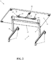
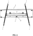
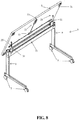
- an article of furniture 1 can include a tabletop 3 that is supported by a base 5.
- the base 5 can include legs 9 that are attached to feet 7.
- Each foot can be a castor so that the article of furniture 1 is rollable or otherwise moveable along a floor.
- each foot can be a stationary, non-moving element that engages the floor to support the base on the floor.
- Each leg 9 can extend vertically from adjacent the feet to which that leg 9 is attached.
- An upper end portion of each leg may be attached to a cross member 11 that extends between the legs 9. For instance, an upper portion of a first leg can be attached to a first end of the cross member 11 and an upper portion of the second leg can be attached to the second end of the cross member 11 that is opposite the first end of the cross member 11.
- the tabletop 3 can be rotatably or tiltably attached to the cross member 11 or other structure of the base 5 so that the tabletop 3 is tiltable about at least one horizontal axis so that the tabletop can be moved from a first position to a second position and also moved from that second position back to its first position.
- the tabletop 3 can be attached to the cross member 11 via a tilting mechanism 10.
- An example of such a tilting mechanism 10 is disclosed in U.S. Patent No. 9,265,340 .
- the tilting mechanism 10 that may rotatably or tiltably connect the tabletop 3 to the base 5 can be configured so that only the tabletop's position is moved when the tabletop is rotated between different positions when the tilting mechanism 10 is utilized to adjust the position of the tabletop 3.
- the tilting mechanism may also move when the tabletop 3 is moved.
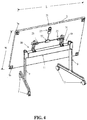
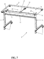
- the tilting mechanism 10 can be configured to be coupled to a leg rotating mechanism so that the legs 9 of the article of furniture twist or rotate when the tabletop 3 is rotated between first and second positions.
- a tilting mechanism coupled to leg rotating mechanism is shown in Figures 7-8 of this application.
- An example of such a tilting mechanism configuration is also described in U.S. Patent No. 9,265,340 (e.g. tilting mechanism 14 disclosed in U.S. Patent No. 9,265,340 that is coupled to at least one leg rotating mechanism 13 disclosed in U.S. Patent No. 9,265,340 ).
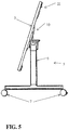
- the first position of the tabletop is a position in which the tabletop 3 is horizontal or is only slightly inclined or declined (e.g. is within 5-10 degrees of being horizontal).
- the second position of the tabletop may position the tabletop 3 so that is vertical or is substantially vertical (e.g. is within 45 degrees of being vertical, is within 30 degrees of being vertical, or is within 10 degrees of being vertical, etc.).
- the tabletop may have a front edge 3a and a rear edge 3b when in the first position.
- the front and rear edges 3a and 3b may be at the same height or may be close to being at the same height (e.g. within 0-25 centimeters of being at the same height).
- the front edge 3a When the tabletop is moved to its second position, the front edge 3a may be located at a position that is significantly higher than the rear edge 3b. For instance, the front edge 3a may be higher than the rear edge 3b by the full width W of the tabletop 3, by no more than the full width W of the tabletop 3, by at least half the width W of the full tabletop, or by about half the width W of the tabletop 3 (e.g. 40-60% of the width W of the tabletop 3 or 45% to 55% of the full width W of the tabletop, etc.).
- Each damper 31 may be configured as a gas spring or other type of damper to help regulate the speed at which the tabletop 3 may move from a use position to a nesting position.
- Each damper 31 can have a first end attached to the base 5 (e.g. a portion of cross member 11 or a portion of the tilting mechanism 10) and have a second end that is opposite its first end attached to the table top (e.g. the bottom surface of the tabletop 3).
- an end of an extendable arm of a damper 31 that is extendable from a receptacle member of the damper 31 and is also retractable back into the receptacle member of the damper 31 is attached to the base 5 (e.g. cross member 11, tilting mechanism 10, etc.) while the receptacle member is attached to the tabletop 3 (e.g. the bottom surface of the tabletop 3).
- the extendable arm of the damper 31 is attached to the tabletop 3 (e.g. bottom surface of the tabletop 3, etc.) and the receptacle member of the damper 31 may be attached to the base 5 (e.g. cross member 11, tilting mechanism 10, etc.).
- the distal end of the extendable arm of the damper 31 that is positioned outside of the receptacle member can be pivotally attached to the base 5 or tabletop 3.
- the receptacle member of the damper 31 that retains the proximate end of the extendable arm that is moveably retained within a chamber of the receptacle member may also be pivotally attached to the base 5 or the tabletop 3.
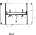
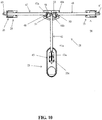
- the motion of the tabletop 3 between its first and second positions can be actuated and/or permitted via a latch mechanism 21 that may be attached to the bottom surface 3c of the tabletop 3.
- the latch mechanism 21 may be adjustable from a locked position to an unlocked position. In some embodiments, the latch mechanism 21 is biased to its locked position so that a user must manipulate the latch mechanism to provide a force for moving the latch mechanism to the unlocked position.
- the tabletop 3 When the latch mechanism 21 is in the unlocked position, the tabletop 3 may be rotatable via the tilting mechanism 10 that tiltably connects the tabletop 3 to the base 5 from the tabletop's first position to its second position.
- the latch mechanism 21 can be configured to prevent tilting of the tabletop 3 from the first position to the second position.
- the latch mechanism 21 can include an actuator mechanism 23 that is configured so that a user may manipulate the actuator mechanism 23 to adjust the latch mechanism 21 from its locked position to its unlocked position to facilitate adjustment of the tabletop from its first position to its second position.
- the latch mechanism 21 may also include detent mechanisms 25 and an articulation mechanism 27 that is positioned between the detent mechanisms 25 and the actuation mechanism 23.
- the detent mechanisms 25 can include a first detent mechanism 26 and a second detent mechanism 28.
- the first detent mechanism 26 can include a first elongated member 47 that extends between a first moveable detent member 63 and the articulation mechanism 27.
- a first end 47a of the first elongated member 47 can be attached to a first rotatable member 51 that is rotatably positioned within a housing 27a of the articulation mechanism 27.
- the first end 47a may be pivotally attached to the first rotatable member 51 via a pivot pin 48 or other type of connector or connection mechanism.
- a second end 47b of the first elongated member 47 is positioned opposite the first end 47a.
- the second end 47b can be affixed to the first detent member 63 or otherwise attached to the first detent member 63.
- the second end 47b can have a hole through which a portion of the first detent member 63 extends that is sized and configured to attach the first detent member to the second end 47b.
- a first spring member 65 can be attached between the second end 47b and a housing 25a of the first detent mechanism 26 to bias the detent member 63 to an extended position in which the first detent member 63 extends out of the housing 25a and into a first aperture formed in a structure of the base 5 or attached to the base 5 for locking the position of the tabletop in its first position.
- the first aperture in which the first detent member 63 is positionable into can be an aperture formed in the tilting mechanism 10 or an aperture defined by a cross member 11 or a bracket or other structure attached to the cross member 11 or other component of the base 5.
- a protuberance that extends along a perimeter (e.g. a circumference or other type of perimeter) of an intermediate portion or middle portion of the first detent member 63 may contact a first end of the first spring member 65 and a second end of the spring member 65 that is opposite its first end may contact an inner wall defined by the housing 25a of the detent mechanism that may be located within an inner opening 25b defied in the housing 25a to bias the first detent member to its extended, locking position.
- the first spring member 65 may be a coil spring or other type of spring member for such embodiments.
- the first spring member 65 may define or have an inner channel or other type of inner aperture that is sized to receive a portion of the first detent member 63 between the second end of the first spring member 65 that may be in contact with or engagement with an inner wall of the housing 25a and the first end of the first spring member 65 that is in contact with or otherwise engaging a protuberance of the intermediate portion of the first detent member 63.
- the second detent mechanism 28 can include a second elongated member 49 that extends between a second moveable detent member 61 and the articulation mechanism 27.
- a first end 49a of the second elongated member 49 can be attached to a second rotatable member 53 that is rotatably positioned within the housing 27a of the articulation mechanism 27.
- the first end 49a of the second elongated member 49 may be pivotally attached to the second rotatable member 53 via a pivot pin 50 or other type of connector or connection mechanism.
- a second end 49b of the second elongated member 49 can be positioned opposite the first end 49a.
- the second end 49b can be affixed to the second detent member 61 or otherwise attached to the second detent member 61.
- the second end 49b can have a hole 49c through which a portion of the second detent member 63 extends that is sized and configured to attach the second detent member 61 to the second end 49b.
- a second spring member 67 can be attached between the second end 49b and a housing 25a of the second detent mechanism 28 to bias the second detent member 61 to an extended position in which the second detent member 61 extends out of the housing 25a and into a second aperture formed in a structure of the base 5 or attached to the base 5 for locking the position of the tabletop 3 in its first position.
- the second aperture in which the second detent member 61 is positionable into can be an aperture formed in the tilting mechanism 10 or an aperture defined by a cross member 11 or a bracket or other structure attached to the cross member 11 or other component of the base 5.
- the second spring member 67 may have a first end that contacts or otherwise engages a protuberance 61a or ring element attached to an intermediate portion or middle portion of the second detent member 61.
- the second end of the second spring member 67 may contact an inner wall, rib, or other element defined in the housing 25a that is positioned in or adjacent an opening 25b that is configured to retain at least a portion of the second detent member 61.
- the second spring member 67 may be a coil spring or other type of spring element for such embodiments.
- the second spring member 67 may include or define an inner channel that is sized to receive a portion of the second detent member between the second end of the second spring member 67 and the first end of the second spring member 67 that contacts or otherwise engages the peripherally positioned protuberance 61a attached to the intermediate portion of the second detent member 61.
- each protuberance 61a that is positioned on the periphery of the first and second detent members 63 and 61 extends along a circumference or other portion of the perimeter of the width or thickness of the detent member may be a ring element attached to the detent member.
- the protuberance 61a is a peripheral wall, lip, or other type of protuberance that is formed or otherwise defined on the exterior surface of the detent member that extends along a circumference or other portion of the perimeter of the width or thickness of the detent member.
- the opening or mouth of the second aperture that receives the second detent member 61 faces towards the opening or mouth of the first aperture that receives the first detent member 63.
- the first and second detent members 63 and 61 move toward each other when the latch mechanism is moved to an unlocked position in which the first and second detent members 63 and 61 are retracted out of the first and second apertures.
- the first and second detent members 63 and 61 may move away from each other when moved from their retracted, unlocked positions to their extended locked positions located within the first and second apertures.
- the path of travel of the retraction and extension of the first and second detent members 63 and 61 is a linear path of travel. That path of travel for each detent member can be defined by an opening 25b that is defined in the housing 25a of the detent mechanism 25, the spring member engaging that detent member and/or motion of the elongated member to which that detent member is attached.
- the path of travel that is at least partially defined by the opening 25b can be configured so that the detent member retracts into the opening 25b via a mouth of that opening that is at least partially defined in the exterior surface of the housing 25a and the shape of the opening 25b formed within the housing 25a.
- the articulation mechanism 27 can be positioned between the actuation mechanism 23 and the detent mechanisms 25 and be configured so that a force provided by a user via the actuation mechanism 23 is translated to the detent mechanisms 25 to move those detent mechanisms from their locked positions to their unlocked positions while also permitting the detent mechanisms 25 to be moved back to their locked positions when that force from a user is removed.
- the articulation mechanism 27 can include a housing 27a that has a central opening 27b that is sized to receive a first rotatable member 51 and a second rotatable member 53.
- the housing 27a of the articulation mechanism 27 can also include a first channel 27d that is in communication with the opening 27b that is sized and configured to permit the first elongated member 47 to extend from the first rotatable member, through this first channel 27d to the first detent mechanism 26.
- the housing 27a can also define a second channel 27c that is in communication with the opening 27b that is sized and configured to permit the second elongated member 49 to extend from the second rotatable member 53 to the second detent mechanism 28.
- the first and second channels 27d and 27c can each be sized and shaped as a groove, recess, furrow, chamber, or other type of channel.
- first and second channels 27d and 27c are each polygonally shaped or otherwise configured to define a linear length along which an elongated member (e.g. first elongated member 47 or second elongated member 49) can extend along such that the elongated member extends linearly through the channel.
- each channel 27d and 27c are also configured to have a width that is sufficient to permit the width of that elongated member to be flatly positioned in that channel.
- the housing 27a of the articulation mechanism 27 can also include a third channel 27e that is defined by the housing to be in communication with the opening 27b to receive a first end portion 41a of a third elongated member 41 so that the third elongated member 41 can extend from the actuation mechanism 23 to the first and second rotatable members 51 and 53 of the articulation mechanism 27 positioned in the opening 27b.
- the third channel 27e can be sized and configured to be polygonally shaped or otherwise configured to define a linear length along which an elongated member (e.g. third elongated member 41) can extend along such that the elongated member extends linearly through the channel.
- the third channel 27e is also configured to have a width that is sufficient to permit the width of that elongated member to be flatly positioned in that channel.
- the first end portion 41a can also be attached to the first and second rotatable members via a connector 57 that can pass through a hole in the first end portion 41a and holes in the first and second rotatable members 51 and 53. These holes may each be aligned with each other so that the connector 57 can linearly pass through all of these holes for connecting the third elongated member 41 to the first and second rotatable members 51 and 53 at a connection point.
- the connector 57 can be configured so that it defines a pivot point or axis of rotation for both the first rotatable member 51 and the second rotatable member 53.
- the connector 57 is a pin, bolt, screw, or other type of fastener.
- another type of connection mechanism is used instead of a fastener to connect the third elongated member 41 to the first and second rotatable members 51 and 53, such as an adhesion mechanism, welding, or other type of connection mechanism.
- the first and second rotatable members 51 and 53 may have end portions that are sized and configured to permit their end portions to overlap each other so that their holes may be aligned with each other in the opening 27b.
- the first rotatable member 51 may have its inner side end configured to lay underneath the inner side of the second rotatable member 53 so that the holes of the first and second rotatable members are linearly aligned with each other so that a shaft of the connector 57 can pass through those holes as well as the hole in the first end portion 41a of the third elongated member 41.
- the second rotatable member 53 may have its inner side end configured to lay underneath the inner side of the first rotatable member 51 so that the holes of the first and second rotatable members are linearly aligned with each other so that a shaft of the connector 57 can pass through those holes as well as the hole in the first end portion 41a of the third elongated member 41.
- the inner sides of the first and second rotatable members 51 and 53 may also be shaped or otherwise configured to facilitate rotatable motion of each rotatable member about the pivot axis or rotational axis that may be defined by the connector 57 (e.g.
- each inner side portion may include recesses or other profiles that are rounded or curved to facilitate rotation of the first and second rotatable members 51 and 53 about the axis of rotation defined by the connector 57.
- the third elongated member 41 may extend from its first end portion 41a attached to the first and second rotatable members 51 and 53 inside the opening 27b of the housing 27a of the articulation mechanism 27 to its second end portion 41b that may be opposite its first end portion 41a.
- the second end portion 41b can be attached to the actuation mechanism 23.
- the second end portion 41b can be attached to a moveable component of the housing of the articulation mechanism or to a moveable component of the actuation mechanism positioned inside of or moveably attached to that housing.
- the actuation mechanism 23 can include a housing that is at least partially formed by a first component 23a being connected to a second component 23b.
- a fastener 23j such as a bolt or screw, may connect the first and second components 23a and 23b together.
- Another type of connection mechanism may alternatively (or also) be used to connect the first and second components 23a and 23b together. For instance, one or more mating profiles or interlocking profiles may be utilized to connect the first and second components together and/or an adhesive or welding may be used for connecting the first and second components 23a and 23b together.
- the first and second components 23a and 23b When connected together, the first and second components 23a and 23b may form a housing that has a cavity 23e and an opening 23i that is sized to receive a guide member 23c that may be fastened or otherwise attached to a bottom surface of the tabletop 3.
- the guide member 23c may be immovably attached to the tabletop so that the guide member is not moveable relative to the tabletop (e.g. is screwed, adhered, or otherwise immovably affixed to the bottom surface of the tabletop 3).
- the housing formed via connection of the first and second components 23a and 23b may be moveably attached to the guide member 23c located within the opening 23i and cavity 23e such that the housing is linearly moveable relative to the guide member 23c.
- the housing may have ribs, rails 23f, or other type of protuberances or projections that may moveably fit within grooves 23g formed on opposite sides of the guide member 23c so that the grooves 23g at least partially define the path of travel of the housing formed by the first and second components 23a and 23b.
- rails 23f may slide along the grooves 23g so that the housing moves linearly relative to the guide member 23c along a path defined by the grooves 23g and the rails 23f slideably positioned in the grooves 23g.
- the guide member 23c has rails or other projections or protuberances that extend form opposite sides of the guide member 23c and the housing defined by the first and second components 23a and 23b being connected together has grooves for receiving those rails to facilitate the relative linear motion of the housing relative to the guide member.
- the housing slides relative to the guide member 23c via a linear path defined by the rails being positioned within those grooves such that the housing can slide along the rails of the guide member 23c.
- the extent to which the housing formed by the first and second components 23a and 23b may move relative to the guide member 23c can be defined by a length of the opening 23i and/or cavity 23e in which the guide member is located within the housing.
- the guide member 23c When the housing is in a first position, the guide member 23c may be located adjacent a first end of the opening 23i and/or cavity 23e. For instance, a first end of the guide member 23c may contact a portion of the housing defining the first end of the opening 23i and/or cavity 23e.
- the housing When the housing is moved relative to the guide member 23c via a force provided by a user to its second position, the housing may be prevented from further motion when the guide member 23c is positioned at the second end of the opening 23i and/or cavity 23e such that a portion of the housing that defines the second end of the opening 23i and/or cavity 23e contacts the second end of the guide member 23c that is opposite its first end.
- a stopper, wall, or other structure may be located within the cavity 23e and/or opening 23i adjacent to opposite sides of the cavity 23e and/or opening 23i to contact the guide member 23c when the housing is moved between its first and second positions to define the extent to which the housing may move in a first direction from its first position to its second position and the extent to which the housing may move in a second direction that is opposite the first direction from its second position to its first position.
- the first component 23a can include an end having an opening 23h and the second component 23b can also include an opening so that when the housing is formed by connection of the first and second components 23a and 23b, there is an opening that is sized and configured to permit a user to place his or her hand or fingers of that user's hand into the opening to provide a force for moving the housing so that the housing is slideable or otherwise moveable relative to the guide member 23c attached within the housing and/or adjacent an intermediate portion of the housing and/or end portion of the housing opposite this opening.
- the force that is applied by the user is a pulling force to pull the housing to move the housing relative to the guide member 23c.
- the force that is applied is a pushing force to push the housing to move the housing relative to the guide member 23c.
- the actuation mechanism 23 can also include a biasing mechanism 43.
- the biasing mechanism 43 can include a third spring 43a or other type of biasing element that is configured to help bias the housing of the actuation mechanism in a first position that correspond to a locked position for the first and second detent members 63 and 61 of the detent mechanisms.
- the third spring 43a may be a coil spring, an elongated elastomeric member, or other type of spring element that has a first end and a second end opposite its first end.
- the guide member 23c can include an opening 23d (e.g. a recess, channel, or cavity) that is sized and configured to retain the first end of the third spring 43a as well as an intermediate portion of the third spring 43a adjacent to this first end.
- the first end of the third spring 43a may be attached to the guide member adjacent to the opening 23d.
- the second end of the third spring 43a may be attached to the first component 23a and/or the second component 23b adjacent to an end of the opening 23i and/or cavity 23e that is opposite the end of the opening 23i and/or cavity 23e at which the guide member 23c and/or first end of the third spring 43a may be positioned.
- the opening 23d of the guide member can be configured so that when the housing of the actuation mechanism 23 is moved relative to the guide member 23c from its first position to its second position, the second end of the third spring 43a is moved closer to the first end of the third spring 43a attached to the guide member 23c as the third spring 43a is compressed via motion of the housing such that the opening 23d receives a greater portion of the spring therein as the third spring 43a is compressed.
- the third spring 43a may be compressed as the user applies a force to overcome the force exerted by the third spring 43a that may bias the position of the housing to its first position via motion of the housing causing the third spring 43a to compress and causing a greater portion of the third spring 43a to move into the opening 23d of the guide member 23c.
- the spring When the user removes the applied force, the spring may decompress and thereby extend back to its previous length so that its second end moves farther away from its first end, which can also drive motion of the housing relative to the guide member from the second position to its original, first position. Such motion may also result in moving the detent members of the detent mechanisms 25 back to their locked positions.
- the compression of the third spring 43a that can result when the housing of the actuation mechanism 23 is moved from its first position to its second position may also result in the length of the third spring 43a changing from a first length to a second length that is shorter than the first length.
- Decompression of the third spring 43a that can occur when the housing of the actuation mechanism 23 is moved from its second position to its first position may also result in the length of the third spring 43a changing from its second length to its first length, which is longer than the second length.
- the latch mechanism 21 can be manipulated by a user to allow the tabletop 3 to be moved from a first position to a second position. Operation of the latch mechanism 21 by a user can occur such that a user uses his or her hand or one or more fingers of the user's hand to provide a force on a movable housing of the actuation mechanism 23.
- the housing may move linearly relative to the guide member 23c when the user provides a force that overcomes a biasing force exerted by the third spring 43a and/or first and second springs 65 and 67.
- Motion of the housing from its first position to its second position can cause the second end 41b of the third elongated member to move with the housing of the actuation mechanism 23 away from the housing 27a of the articulation mechanism 27.
- This motion may be a linear motion.
- the moving away of the third elongated member 41 can cause the first end 41a of the elongated member to move linearly away from the housing 27a of the articulation mechanism such that a portion of the third elongated member passes out of the third channel 27e.
- Connector 57 that is attached to the first end 41a of the third elongated member 41 moves with the third elongated member such that this connector also moves linearly with the third elongated member.
- the motion of the third elongated member 41 and connector 57 causes the first and second rotatable members 51 and 53 to rotate about the connector 57.
- Rotation of the first rotatable member 51 driven by the motion of the third elongated member 41 moving away from the articulation mechanism 27 causes that first end 47a of the first elongated member 47 to move away from the first detent mechanism 26 and into the opening 27b of the articulation mechanism by a portion of the first elongated member moving through the first channel 27d and into the opening 27b of the housing 27a of the articulation mechanism 27
- This motion of the first elongated member 47 causes the first detent member 63 to move into the housing 25a of the first detent mechanism 26 and out of an aperture in which it may be positioned that is located in structure of the base 5 or a structure of the tilting mechanism 10 attached to the base 5 so that the detent member is moved out of its locked position and outside of that structure into an unlocked position.
- Motion of the first detent member 63 into the housing 25a of the first detent mechanism 26 may cause the first spring member 65 to compress.
- Rotation of the second rotatable member 53 also drives motion of the second elongated member 49 at the same time rotation of the first rotatable member 51 is driven by the motion of the third elongated member 41.
- the rotation of the second rotatable member causes the first end 49a of the second elongated member 49 to move further into the opening 27b such that a portion of the second elongated member 49 passes through the second channel 27c and into the opening 27b so that the second elongated member 49 moves away from the housing of the second detent mechanism 28.
- This motion of the second elongated member 49 causes the second detent member 61 attached to the second end 49b of the second elongated member 49 to move further into the housing 25a of the second detent mechanism 28 so that the second detent member 63 is moved from its locked position that is located in a structure of the base 5 or a structure of the tilting mechanism 10 attached to the base 5 to an unlocked position in which that detent member is positioned outside of that structure.
- Motion of the second detent member 61 into the housing 25a of the second detent mechanism 28 may cause the second spring 67 to compress.
- first and second spring members 65 and 67 compression of the first and second spring members 65 and 67 can result in the length along which these spring extend from their first ends to their second ends to change from a first length to a second length that is shorter than the first length.
- the lengths of the springs may correspondingly also change from the second length to the first length that is longer than the second length.
- motion of the first and second detent members from their locked positions to their unlocked positions is a linear motion that is in opposite directions.
- the directions of motion may be parallel to each other.
- the direction of motion of the first and second detent members 63 and 61 may be a direction of motion that is perpendicular to the direction of motion of the moveable housing of the actuation mechanism 23.
- the paths of travel that the detent members move along when moving between their locked and unlocked positions are paths that extend in a direction that is transverse to a path of motion that the housing of the actuation mechanism 23a moves along when the detent members and the housing are moved between their first and second positions (e.g. between their locked and unlocked positions).
- the path of travel of the first and second detent members may each extend along a path of travel that extends along a length L of the tabletop 3 and the path of motion of the moveable housing of the actuation mechanism 23 may extend along a path of travel that extends along the width W of the tabletop.
- the actuation mechanism is manipulated by a user to move the housing from its first position to its second position, which causes the first and second detent members 63 and 61 to move from their locking positions to their unlocked positions
- the user may be able to provide an upward force on a side of the tabletop or a downward force on a side of the tabletop to cause the tabletop 3 to flip from its first position to its second position.
- the article of furniture may then be moved next to other articles so positioned for compact nesting of the articles of furniture and/or storage of the articles of furniture so that the article of furniture takes up less floor space (e.g. less area of a floor space).
- the first spring member 65, second spring member 67, and third spring 43a may each extend from their compressed positions to their decompressed positions, which can provide a biasing force that functions to move the first and second detent members 63 and 61 from their unlocked positions to a more extended position out of the housings 25a of the first and second detent mechanisms 26 and 28 and, at the same time, also causes the third elongated member 41 to move toward the articulating mechanism 27 such that the first end 41a of the third elongated member 41 moves further inward via the third channel 27e into the housing 27a of the articulation mechanism 27 to return the housing of the actuation mechanism 23 to move relative the guide member 23c so that it moves from its second position back to its first position.
- the motion of the first detent member 63 is also facilitated via the motion of the first elongated member 47 being moved away from the housing 27a of the articulation mechanism 27 toward the housing of the first detent mechanism 26 such that a portion of the first elongated member 47 passes from the opening 27b of the housing into the first channel 27c .
- the motion of the second detent member 61 is also facilitated via the motion of the second elongated member 49 being moved away from the housing 27a of the articulation mechanism 27 toward the housing of the second detent mechanism 28 such that a portion of the second elongated member 49 passes from the opening 27b of the housing into the second channel 27d .
- the first and second detent members 63 and 61 may not extend into apertures formed in structures of the base 5 and/or tilting mechanism 10 of the article of furniture 1. If the user releases the actuation mechanism 23 when the tabletop 3 is in its first position, the detent members may extend back into these apertures.
- the user When the user wishes to move the tabletop 3 from its second position back to its first position, the user need not provide any force on the actuation mechanism 23. The user may simply provide a force for causing rotation of the tabletop 3 to return the tabletop to its first position.
- the first spring member 65, second spring member 67, and third spring 43a may each compress as the detent members 63 and 63 engage structures that they may pass by during the motion of the tabletop 3 back to its first position so that the housing of the actuation mechanism 23 and detent members move as needed to facilitate positioning of the tabletop 3 back to its first position.
- the detent members and housing of the actuation mechanism 23 may automatically be moved via the biasing force provided by the first spring member 65, second spring member 67, and third spring 43a so that the first and second detent members 63 and 61 are moved into their locked positions within apertures of the structures of the base 5 and/or tilting mechanism 10 while the housing of the actuation mechanism 23 is also returned to its first position.
- a user may have to adjust a locking mechanism, actuate the latch mechanism, or provide a force sufficient to overcome a tabletop gripping mechanism that may engage a portion of the tabletop 3 to help maintain the tabletop in its second position for moving the tabletop 3 from its second position to its first position (e.g. a work position in which the work surface of the tabletop is horizontal or substantially horizontal).
- Embodiments of the method may include moving a tabletop 3 into its first position for use of the tabletop as a work surface. Thereafter, the actuation mechanism 23 may be manipulated to move the first and second detent members 63 and 61 to their unlocked positions and, while held in those unlocked positions via a user's application of force, the tabletop may be moved out of its first position. The tabletop 3 may then be moved to its second position and subsequently moved along a floor to be nested and/or stored next to other articles of furniture having their tabletops 3 in their second position.
- the user may move the article out of its nested and/or stowed position and move the article of furniture along a floor to a desired location.
- the tabletop may then be moved from its second position back to its first position.
- the user or others may then use the tabletop 3 as a work surface for a meeting, performing work, for training, or for another type of activity.
- Embodiments of the article of furniture may be configured as a table having a tabletop 3.
- the article of furniture is configured as a seating device or other type of furniture.
- the tabletop 3 could alternatively be configured as an elongated seat of a bench that is supported on a floor by a base.
- the latch mechanism 21 is positioned on an underside of the seat of the bench.
- the guide member 23c may be configured to be attached adjacent to the housing of the actuation mechanism such that the guide member 23c is outside of the housing of the actuation mechanism 23 and engages opposite sides of the housing of the actuation mechanism 23.
- the guide member has stops defined therein or attached thereto to control an extent of travel for the housing as it moves between its first and second positions.
- the shape and size of the tabletop, work surface or other structure of the furniture can be any of a number of different shapes and sizes.
- the tabletop is defined by one unitary structure (e.g.
- a tabletop formed of one unitary piece of stone, wood, composite material, polymeric material, or metal) or by interconnected structures fastened or otherwise joined together (e.g. a tabletop that is comprised of two or more interconnected pieces where each piece is connected to at least one other piece by a fastening mechanism such as adhesive, welding, fasteners, or other type of fastening apparatus).
- the tabletop is another type of work surface, such as the seat of a bench that is configured to be sat on when it is in the first position.
- first and second spring members 65 and 67 may each be a coil spring or another type of spring element such as an elongated elastomeric member having a channel therein sized to receive a portion of the detent member to which that spring is to engage.
- the third spring 43a may be a coil spring or may alternatively be another type of spring such as, for example, an elastomeric strap or other type of elastomeric member.
- the first, second and third elongated members 47, 49, and 41 may be rods, straps, bars, rails, or other types of elongated members composed of metal, a composite material, a polymeric material, an elastomeric material, or other type of material.
- first and second rotatable members 51 and 53 may be triangularly shaped, circularly shaped, generally polygonally shaped, or elliptically shaped and may be composed of metal, a polymeric material, or a composite material.
- first and second detent members 63 and 61 may each be composed of metal, a polymeric material, or a composite material and may each be structured as rod-like structures, bar-like structures, or other type of elongated member.
- the housings of the actuation mechanism, articulation mechanism 27, and detent mechanisms 25 may have any of a number of shapes and sizes and be composed of metal, a composite material, or a polymeric material.
- guide member 23c may be composed of metal, a composite material or a polymeric material and may have any type of suitable shape or size such as a polygonal shape, a circular shape, an oblong shape, or other type of shape.
- each element of the article of furniture and latch mechanism can be composed of any type of material that can help meet a particular design objective such as a metal, an elastomeric material, a polymeric material, or be composed of a combination of such materials due to the interconnection of different structures formed of different types of materials to form that element.
- the housing of the actuation mechanism 23 is configured as a handle or actuator member.
- the housings of the actuation mechanism 23, detent mechanisms 25 and articulation mechanism 27 are configured to fully enclose all the elements of these mechanisms or may be configured to only partially enclose a portion of the mechanisms or only enclose a number of elements of the mechanisms. Therefore, it should be understood that while certain exemplary embodiments of articles of furniture and latch mechanisms for articles of furniture have been discussed and illustrated herein, it is to be distinctly understood that the invention is not limited thereto but may be otherwise variously embodied and practiced within the scope of the following claims.
Landscapes
- Engineering & Computer Science (AREA)
- Mechanical Engineering (AREA)
- Legs For Furniture In General (AREA)
- Drawers Of Furniture (AREA)
- Furniture Connections (AREA)
- Pivots And Pivotal Connections (AREA)
- Tables And Desks Characterized By Structural Shape (AREA)
- Standing Axle, Rod, Or Tube Structures Coupled By Welding, Adhesion, Or Deposition (AREA)
- Closing And Opening Devices For Wings, And Checks For Wings (AREA)
Applications Claiming Priority (3)
| Application Number | Priority Date | Filing Date | Title |
|---|---|---|---|
| US201562151095P | 2015-04-22 | 2015-04-22 | |
| US15/096,387 US9609945B2 (en) | 2015-04-22 | 2016-04-12 | Article of furniture having a latch mechanism |
| PCT/US2016/027183 WO2016171966A1 (en) | 2015-04-22 | 2016-04-13 | Article of furniture having a latch mechanism |
Publications (2)
| Publication Number | Publication Date |
|---|---|
| EP3285616A1 EP3285616A1 (en) | 2018-02-28 |
| EP3285616B1 true EP3285616B1 (en) | 2019-07-03 |
Family
ID=55806842
Family Applications (1)
| Application Number | Title | Priority Date | Filing Date |
|---|---|---|---|
| EP16718138.7A Active EP3285616B1 (en) | 2015-04-22 | 2016-04-13 | Article of furniture having a latch mechanism |
Country Status (6)
| Country | Link |
|---|---|
| US (1) | US9609945B2 (es) |
| EP (1) | EP3285616B1 (es) |
| JP (1) | JP6553208B2 (es) |
| CA (1) | CA2983123C (es) |
| MX (1) | MX361726B (es) |
| WO (1) | WO2016171966A1 (es) |
Families Citing this family (26)
| Publication number | Priority date | Publication date | Assignee | Title |
|---|---|---|---|---|
| USD789127S1 (en) | 2014-04-25 | 2017-06-13 | Bombardier Inc. | Table top |
| USD839638S1 (en) * | 2016-05-27 | 2019-02-05 | Knoll, Inc. | Table |
| USD799861S1 (en) * | 2016-05-27 | 2017-10-17 | Knoll, Inc. | Credenza base |
| WO2018081415A1 (en) | 2016-10-27 | 2018-05-03 | Steelcase Inc. | Flip top table |
| CN207341423U (zh) * | 2017-01-06 | 2018-05-11 | 革新(厦门)运动器材有限公司 | 一种折叠桌的高度调节结构 |
| US10405657B2 (en) | 2017-05-17 | 2019-09-10 | Knoll, Inc. | Bracket mechanism for pre-fabricated office enclosure beams and method of using the same |
| DE102017118562A1 (de) * | 2017-08-15 | 2019-02-21 | Konrad Merkt Gmbh | Tischgestell für ein Tischmöbel |
| CN107692508A (zh) * | 2017-10-25 | 2018-02-16 | 诺梵(上海)家具科技股份有限公司 | 一种具有折叠翻转功能的培训桌 |
| USD879514S1 (en) | 2018-04-16 | 2020-03-31 | Playground Store Limited | Desk |
| USD895325S1 (en) | 2018-04-16 | 2020-09-08 | Playground Store Limited | Desktop with stowed legs |
| WO2019202348A1 (en) | 2018-04-16 | 2019-10-24 | Playground Store Limited | Desk system |
| US10295311B1 (en) * | 2018-05-22 | 2019-05-21 | First Line Furniture, LLC | Flip-top table for protection from projectiles |
| US10866068B1 (en) * | 2018-05-22 | 2020-12-15 | First Line Furniture, LLC | Flip-top table for protection from projectiles |
| US10758038B2 (en) | 2018-05-29 | 2020-09-01 | Knoll, Inc. | Article of furniture and method of using the same |
| US10654315B1 (en) * | 2018-07-03 | 2020-05-19 | Gf Health Products, Inc. | Adjustable height table base with transport mechanism |
| WO2020035809A1 (en) * | 2018-08-16 | 2020-02-20 | Fleetwood Group, Inc. | Folding furniture latch assembly |
| CA186072S (en) * | 2018-08-21 | 2020-07-08 | Inter Ikea Systems Bv | Table |
| USD883693S1 (en) * | 2018-10-19 | 2020-05-12 | Pedrali S.P.A. | Chair |
| IT201900006990A1 (it) * | 2019-05-20 | 2020-11-20 | Metalmeccanica Alba Srl | Struttura di tavolo con piano ribaltabile |
| CN110432651B (zh) * | 2019-09-06 | 2024-06-25 | 常州市莱特气弹簧有限公司 | 一种折叠桌 |
| USD998997S1 (en) | 2020-07-01 | 2023-09-19 | United States Postal Service | Sorting table |
| US11517104B2 (en) | 2020-07-01 | 2022-12-06 | United States Postal Service | Portable and foldable workstation apparatus |
| CN113040513B (zh) * | 2021-03-31 | 2023-05-16 | 江西锐胜台球制造有限公司 | 一种可锁紧收缩的插销装置 |
| US12022960B2 (en) | 2021-05-04 | 2024-07-02 | Knoll, Inc. | Furniture, charging port assembly, and method of assembling same |
| US11927042B2 (en) | 2021-07-30 | 2024-03-12 | Airbus Americas, Inc. | Quick-release hinge devices, systems and methods |
| US12070123B2 (en) | 2022-11-16 | 2024-08-27 | Lakeshore Learning Materials, Llc | Table with rotating tabletop |
Family Cites Families (30)
| Publication number | Priority date | Publication date | Assignee | Title |
|---|---|---|---|---|
| US2533173A (en) * | 1947-03-26 | 1950-12-05 | Einer W Dahlgren | Folding leg table with actuator mechanism |
| US3413593A (en) | 1967-11-03 | 1968-11-26 | Joseph K. Schaefer | Isolated electrical terminal connection |
| US4986195A (en) | 1988-09-28 | 1991-01-22 | Howe Furniture Corporation | Tilting table top mechanism |
| JP2525308Y2 (ja) * | 1991-07-31 | 1997-02-12 | コクヨ株式会社 | テーブル |
| GB9624984D0 (en) | 1996-11-30 | 1997-01-15 | Wessgold Interiors Limited | Item of furniture |
| JP3122379B2 (ja) * | 1997-01-30 | 2001-01-09 | 愛知株式会社 | 天板ロック装置 |
| DK1217918T3 (da) | 1999-08-23 | 2003-11-10 | Wilkhahn Wilkening & Hahne | Bord med vipbar bordplade |
| ITTO20010577A1 (it) | 2001-06-15 | 2002-12-15 | Pro Cord Spa | Tavolo pieghevole |
| DE20118884U1 (de) | 2001-10-02 | 2002-02-07 | Cornelius, Christian, 32423 Minden | Mit Füßen versehene, verschwenkbare Platte |
| US6845723B2 (en) | 2002-10-31 | 2005-01-25 | Hon Technology Inc. | Folding and tilting table |
| US20080178778A1 (en) * | 2004-04-27 | 2008-07-31 | Paul Koning | Latch assembly with remote release |
| US7066098B2 (en) | 2004-05-14 | 2006-06-27 | Hni Technologies Inc. | Nesting table with controlled pivoting movement |
| EP1712151B1 (en) | 2005-04-13 | 2013-01-23 | Pro-Cord S.p.A. | Nesting and folding table |
| US7677184B2 (en) * | 2005-12-15 | 2010-03-16 | Steelcase Development Corporation | Flip top table |
| DE202006003762U1 (de) | 2006-03-08 | 2007-07-12 | WINI Büromöbel Georg Schmidt GmbH & Co. KG | Tisch |
| US7712422B2 (en) | 2006-07-19 | 2010-05-11 | Sico Incorporated | Folding table |
| EP1958537B1 (en) | 2007-02-19 | 2014-04-30 | Pro-Cord S.p.A. | Nesting and folding table |
| US8091488B2 (en) | 2007-11-07 | 2012-01-10 | Berco Industries, Inc. | Flip top mechanism for table with nesting capabilities |
| US8578864B2 (en) | 2008-02-14 | 2013-11-12 | DSA International, Inc. | Removable attachment bar for a flip-top table |
| US8171863B2 (en) | 2008-02-14 | 2012-05-08 | DSA International, Inc. | Flip-top table mechanism |
| US8051784B2 (en) | 2008-05-14 | 2011-11-08 | Chuan-Fu Hsu | Folding device for a tabletop |
| DE102008037285B4 (de) | 2008-08-11 | 2010-07-22 | Korb & Korb Innenarchitektur Und Design | Tisch mit einer schwenkbaren Tischplatte |
| DE102008052538B4 (de) * | 2008-10-21 | 2021-09-16 | Brunner Gmbh | Tisch mit schwenkbarer Tischplatte |
| ATE515211T1 (de) * | 2009-04-09 | 2011-07-15 | Steelcase Werndl Ag | Klapptisch |
| EP2255694B1 (de) | 2009-05-27 | 2012-01-18 | Steelcase Werndl Aktiengesellschaft | Kupplungseinrichtung, insbesondere für eine Möbel-Verstelleinrichtung |
| ATE515210T1 (de) * | 2009-05-27 | 2011-07-15 | Steelcase Werndl Ag | Verriegelungsmechanismus |
| US8297208B2 (en) | 2009-06-09 | 2012-10-30 | Ditto Sales, Inc. | Tilting tabletop mechanism |
| US8069795B1 (en) | 2009-06-11 | 2011-12-06 | Krueger International, Inc. | Grip latch and hinge mechanism for a flip table |
| US8359983B2 (en) | 2011-06-02 | 2013-01-29 | Halcon Inc. | Adjustable table apparatus and method |
| US9265340B2 (en) | 2013-10-28 | 2016-02-23 | Knoll, Inc. | Article of furniture and method of stacking the same |
-
2016
- 2016-04-12 US US15/096,387 patent/US9609945B2/en active Active
- 2016-04-13 JP JP2017555284A patent/JP6553208B2/ja active Active
- 2016-04-13 WO PCT/US2016/027183 patent/WO2016171966A1/en active Application Filing
- 2016-04-13 EP EP16718138.7A patent/EP3285616B1/en active Active
- 2016-04-13 CA CA2983123A patent/CA2983123C/en active Active
- 2016-04-13 MX MX2017013618A patent/MX361726B/es active IP Right Grant
Non-Patent Citations (1)
| Title |
|---|
| None * |
Also Published As
| Publication number | Publication date |
|---|---|
| EP3285616A1 (en) | 2018-02-28 |
| WO2016171966A1 (en) | 2016-10-27 |
| US20160309888A1 (en) | 2016-10-27 |
| CA2983123C (en) | 2023-07-04 |
| MX2017013618A (es) | 2018-03-14 |
| CA2983123A1 (en) | 2016-10-27 |
| MX361726B (es) | 2018-12-13 |
| JP6553208B2 (ja) | 2019-07-31 |
| US9609945B2 (en) | 2017-04-04 |
| JP2018516631A (ja) | 2018-06-28 |
Similar Documents
| Publication | Publication Date | Title |
|---|---|---|
| EP3285616B1 (en) | Article of furniture having a latch mechanism | |
| US11147367B2 (en) | Article of furniture and method of using the same | |
| US10555603B2 (en) | Height adjustable workstation | |
| US9265340B2 (en) | Article of furniture and method of stacking the same | |
| US11413492B2 (en) | Storable exercise bench | |
| US8585136B2 (en) | Chair with coupling companion stool base | |
| US8869715B2 (en) | Tilting tabletop mechanism | |
| US9629451B2 (en) | Article of furniture having a folding mechanism | |
| US20070182222A1 (en) | Student desk | |
| US20160199687A1 (en) | Collapsible exercise machine | |
| US20160324309A1 (en) | Table with an adjustable orientation table top | |
| US20080149000A1 (en) | Adjustable table | |
| US20180271271A1 (en) | Tray table apparatus | |
| US20180228300A1 (en) | Adjustable bouncing frame | |
| CN220360207U (zh) | 能够调整桌面高度的桌子 | |
| US20240251951A1 (en) | Collapsible office furniture | |
| AU2012244282A1 (en) | Locking Mechansim | |
| KR20160148947A (ko) | 높이조절이 가능한 데스크 |
Legal Events
| Date | Code | Title | Description |
|---|---|---|---|
| STAA | Information on the status of an ep patent application or granted ep patent |
Free format text: STATUS: THE INTERNATIONAL PUBLICATION HAS BEEN MADE |
|
| PUAI | Public reference made under article 153(3) epc to a published international application that has entered the european phase |
Free format text: ORIGINAL CODE: 0009012 |
|
| STAA | Information on the status of an ep patent application or granted ep patent |
Free format text: STATUS: REQUEST FOR EXAMINATION WAS MADE |
|
| 17P | Request for examination filed |
Effective date: 20171016 |
|
| AK | Designated contracting states |
Kind code of ref document: A1 Designated state(s): AL AT BE BG CH CY CZ DE DK EE ES FI FR GB GR HR HU IE IS IT LI LT LU LV MC MK MT NL NO PL PT RO RS SE SI SK SM TR |
|
| AX | Request for extension of the european patent |
Extension state: BA ME |
|
| RIN1 | Information on inventor provided before grant (corrected) |
Inventor name: RUZICKA, PAVEL Inventor name: HARPER, MICHAEL Inventor name: KRUSIN, MARC |
|
| DAV | Request for validation of the european patent (deleted) | ||
| DAX | Request for extension of the european patent (deleted) | ||
| GRAP | Despatch of communication of intention to grant a patent |
Free format text: ORIGINAL CODE: EPIDOSNIGR1 |
|
| STAA | Information on the status of an ep patent application or granted ep patent |
Free format text: STATUS: GRANT OF PATENT IS INTENDED |
|
| INTG | Intention to grant announced |
Effective date: 20181218 |
|
| GRAS | Grant fee paid |
Free format text: ORIGINAL CODE: EPIDOSNIGR3 |
|
| RIN1 | Information on inventor provided before grant (corrected) |
Inventor name: RUZICKA, PAVEL Inventor name: HARPER, MICHAEL Inventor name: KRUSIN, MARC |
|
| GRAA | (expected) grant |
Free format text: ORIGINAL CODE: 0009210 |
|
| STAA | Information on the status of an ep patent application or granted ep patent |
Free format text: STATUS: THE PATENT HAS BEEN GRANTED |
|
| AK | Designated contracting states |
Kind code of ref document: B1 Designated state(s): AL AT BE BG CH CY CZ DE DK EE ES FI FR GB GR HR HU IE IS IT LI LT LU LV MC MK MT NL NO PL PT RO RS SE SI SK SM TR |
|
| REG | Reference to a national code |
Ref country code: GB Ref legal event code: FG4D |
|
| REG | Reference to a national code |
Ref country code: CH Ref legal event code: EP Ref country code: AT Ref legal event code: REF Ref document number: 1149924 Country of ref document: AT Kind code of ref document: T Effective date: 20190715 |
|
| REG | Reference to a national code |
Ref country code: IE Ref legal event code: FG4D |
|
| REG | Reference to a national code |
Ref country code: DE Ref legal event code: R096 Ref document number: 602016016296 Country of ref document: DE |
|
| REG | Reference to a national code |
Ref country code: NL Ref legal event code: MP Effective date: 20190703 |
|
| REG | Reference to a national code |
Ref country code: LT Ref legal event code: MG4D |
|
| REG | Reference to a national code |
Ref country code: AT Ref legal event code: MK05 Ref document number: 1149924 Country of ref document: AT Kind code of ref document: T Effective date: 20190703 |
|
| PG25 | Lapsed in a contracting state [announced via postgrant information from national office to epo] |
Ref country code: HR Free format text: LAPSE BECAUSE OF FAILURE TO SUBMIT A TRANSLATION OF THE DESCRIPTION OR TO PAY THE FEE WITHIN THE PRESCRIBED TIME-LIMIT Effective date: 20190703 Ref country code: LT Free format text: LAPSE BECAUSE OF FAILURE TO SUBMIT A TRANSLATION OF THE DESCRIPTION OR TO PAY THE FEE WITHIN THE PRESCRIBED TIME-LIMIT Effective date: 20190703 Ref country code: NL Free format text: LAPSE BECAUSE OF FAILURE TO SUBMIT A TRANSLATION OF THE DESCRIPTION OR TO PAY THE FEE WITHIN THE PRESCRIBED TIME-LIMIT Effective date: 20190703 Ref country code: PT Free format text: LAPSE BECAUSE OF FAILURE TO SUBMIT A TRANSLATION OF THE DESCRIPTION OR TO PAY THE FEE WITHIN THE PRESCRIBED TIME-LIMIT Effective date: 20191104 Ref country code: BG Free format text: LAPSE BECAUSE OF FAILURE TO SUBMIT A TRANSLATION OF THE DESCRIPTION OR TO PAY THE FEE WITHIN THE PRESCRIBED TIME-LIMIT Effective date: 20191003 Ref country code: SE Free format text: LAPSE BECAUSE OF FAILURE TO SUBMIT A TRANSLATION OF THE DESCRIPTION OR TO PAY THE FEE WITHIN THE PRESCRIBED TIME-LIMIT Effective date: 20190703 Ref country code: CZ Free format text: LAPSE BECAUSE OF FAILURE TO SUBMIT A TRANSLATION OF THE DESCRIPTION OR TO PAY THE FEE WITHIN THE PRESCRIBED TIME-LIMIT Effective date: 20190703 Ref country code: FI Free format text: LAPSE BECAUSE OF FAILURE TO SUBMIT A TRANSLATION OF THE DESCRIPTION OR TO PAY THE FEE WITHIN THE PRESCRIBED TIME-LIMIT Effective date: 20190703 Ref country code: AT Free format text: LAPSE BECAUSE OF FAILURE TO SUBMIT A TRANSLATION OF THE DESCRIPTION OR TO PAY THE FEE WITHIN THE PRESCRIBED TIME-LIMIT Effective date: 20190703 Ref country code: NO Free format text: LAPSE BECAUSE OF FAILURE TO SUBMIT A TRANSLATION OF THE DESCRIPTION OR TO PAY THE FEE WITHIN THE PRESCRIBED TIME-LIMIT Effective date: 20191003 |
|
| PG25 | Lapsed in a contracting state [announced via postgrant information from national office to epo] |
Ref country code: RS Free format text: LAPSE BECAUSE OF FAILURE TO SUBMIT A TRANSLATION OF THE DESCRIPTION OR TO PAY THE FEE WITHIN THE PRESCRIBED TIME-LIMIT Effective date: 20190703 Ref country code: IS Free format text: LAPSE BECAUSE OF FAILURE TO SUBMIT A TRANSLATION OF THE DESCRIPTION OR TO PAY THE FEE WITHIN THE PRESCRIBED TIME-LIMIT Effective date: 20191103 Ref country code: ES Free format text: LAPSE BECAUSE OF FAILURE TO SUBMIT A TRANSLATION OF THE DESCRIPTION OR TO PAY THE FEE WITHIN THE PRESCRIBED TIME-LIMIT Effective date: 20190703 Ref country code: GR Free format text: LAPSE BECAUSE OF FAILURE TO SUBMIT A TRANSLATION OF THE DESCRIPTION OR TO PAY THE FEE WITHIN THE PRESCRIBED TIME-LIMIT Effective date: 20191004 Ref country code: LV Free format text: LAPSE BECAUSE OF FAILURE TO SUBMIT A TRANSLATION OF THE DESCRIPTION OR TO PAY THE FEE WITHIN THE PRESCRIBED TIME-LIMIT Effective date: 20190703 Ref country code: AL Free format text: LAPSE BECAUSE OF FAILURE TO SUBMIT A TRANSLATION OF THE DESCRIPTION OR TO PAY THE FEE WITHIN THE PRESCRIBED TIME-LIMIT Effective date: 20190703 |
|
| PG25 | Lapsed in a contracting state [announced via postgrant information from national office to epo] |
Ref country code: TR Free format text: LAPSE BECAUSE OF FAILURE TO SUBMIT A TRANSLATION OF THE DESCRIPTION OR TO PAY THE FEE WITHIN THE PRESCRIBED TIME-LIMIT Effective date: 20190703 |
|
| PG25 | Lapsed in a contracting state [announced via postgrant information from national office to epo] |
Ref country code: DK Free format text: LAPSE BECAUSE OF FAILURE TO SUBMIT A TRANSLATION OF THE DESCRIPTION OR TO PAY THE FEE WITHIN THE PRESCRIBED TIME-LIMIT Effective date: 20190703 Ref country code: EE Free format text: LAPSE BECAUSE OF FAILURE TO SUBMIT A TRANSLATION OF THE DESCRIPTION OR TO PAY THE FEE WITHIN THE PRESCRIBED TIME-LIMIT Effective date: 20190703 Ref country code: RO Free format text: LAPSE BECAUSE OF FAILURE TO SUBMIT A TRANSLATION OF THE DESCRIPTION OR TO PAY THE FEE WITHIN THE PRESCRIBED TIME-LIMIT Effective date: 20190703 Ref country code: IT Free format text: LAPSE BECAUSE OF FAILURE TO SUBMIT A TRANSLATION OF THE DESCRIPTION OR TO PAY THE FEE WITHIN THE PRESCRIBED TIME-LIMIT Effective date: 20190703 Ref country code: PL Free format text: LAPSE BECAUSE OF FAILURE TO SUBMIT A TRANSLATION OF THE DESCRIPTION OR TO PAY THE FEE WITHIN THE PRESCRIBED TIME-LIMIT Effective date: 20190703 |
|
| PG25 | Lapsed in a contracting state [announced via postgrant information from national office to epo] |
Ref country code: SM Free format text: LAPSE BECAUSE OF FAILURE TO SUBMIT A TRANSLATION OF THE DESCRIPTION OR TO PAY THE FEE WITHIN THE PRESCRIBED TIME-LIMIT Effective date: 20190703 Ref country code: SK Free format text: LAPSE BECAUSE OF FAILURE TO SUBMIT A TRANSLATION OF THE DESCRIPTION OR TO PAY THE FEE WITHIN THE PRESCRIBED TIME-LIMIT Effective date: 20190703 Ref country code: IS Free format text: LAPSE BECAUSE OF FAILURE TO SUBMIT A TRANSLATION OF THE DESCRIPTION OR TO PAY THE FEE WITHIN THE PRESCRIBED TIME-LIMIT Effective date: 20200224 |
|
| REG | Reference to a national code |
Ref country code: DE Ref legal event code: R097 Ref document number: 602016016296 Country of ref document: DE |
|
| PLBE | No opposition filed within time limit |
Free format text: ORIGINAL CODE: 0009261 |
|
| STAA | Information on the status of an ep patent application or granted ep patent |
Free format text: STATUS: NO OPPOSITION FILED WITHIN TIME LIMIT |
|
| PG2D | Information on lapse in contracting state deleted |
Ref country code: IS |
|
| 26N | No opposition filed |
Effective date: 20200603 |
|
| PG25 | Lapsed in a contracting state [announced via postgrant information from national office to epo] |
Ref country code: SI Free format text: LAPSE BECAUSE OF FAILURE TO SUBMIT A TRANSLATION OF THE DESCRIPTION OR TO PAY THE FEE WITHIN THE PRESCRIBED TIME-LIMIT Effective date: 20190703 |
|
| PG25 | Lapsed in a contracting state [announced via postgrant information from national office to epo] |
Ref country code: MC Free format text: LAPSE BECAUSE OF FAILURE TO SUBMIT A TRANSLATION OF THE DESCRIPTION OR TO PAY THE FEE WITHIN THE PRESCRIBED TIME-LIMIT Effective date: 20190703 |
|
| REG | Reference to a national code |
Ref country code: CH Ref legal event code: PL |
|
| PG25 | Lapsed in a contracting state [announced via postgrant information from national office to epo] |
Ref country code: LI Free format text: LAPSE BECAUSE OF NON-PAYMENT OF DUE FEES Effective date: 20200430 Ref country code: LU Free format text: LAPSE BECAUSE OF NON-PAYMENT OF DUE FEES Effective date: 20200413 Ref country code: CH Free format text: LAPSE BECAUSE OF NON-PAYMENT OF DUE FEES Effective date: 20200430 |
|
| REG | Reference to a national code |
Ref country code: BE Ref legal event code: MM Effective date: 20200430 |
|
| PG25 | Lapsed in a contracting state [announced via postgrant information from national office to epo] |
Ref country code: BE Free format text: LAPSE BECAUSE OF NON-PAYMENT OF DUE FEES Effective date: 20200430 |
|
| PG25 | Lapsed in a contracting state [announced via postgrant information from national office to epo] |
Ref country code: IE Free format text: LAPSE BECAUSE OF NON-PAYMENT OF DUE FEES Effective date: 20200413 |
|
| PG25 | Lapsed in a contracting state [announced via postgrant information from national office to epo] |
Ref country code: MT Free format text: LAPSE BECAUSE OF FAILURE TO SUBMIT A TRANSLATION OF THE DESCRIPTION OR TO PAY THE FEE WITHIN THE PRESCRIBED TIME-LIMIT Effective date: 20190703 Ref country code: CY Free format text: LAPSE BECAUSE OF FAILURE TO SUBMIT A TRANSLATION OF THE DESCRIPTION OR TO PAY THE FEE WITHIN THE PRESCRIBED TIME-LIMIT Effective date: 20190703 |
|
| PG25 | Lapsed in a contracting state [announced via postgrant information from national office to epo] |
Ref country code: MK Free format text: LAPSE BECAUSE OF FAILURE TO SUBMIT A TRANSLATION OF THE DESCRIPTION OR TO PAY THE FEE WITHIN THE PRESCRIBED TIME-LIMIT Effective date: 20190703 |
|
| PGFP | Annual fee paid to national office [announced via postgrant information from national office to epo] |
Ref country code: GB Payment date: 20240429 Year of fee payment: 9 |
|
| PGFP | Annual fee paid to national office [announced via postgrant information from national office to epo] |
Ref country code: DE Payment date: 20240429 Year of fee payment: 9 |
|
| PGFP | Annual fee paid to national office [announced via postgrant information from national office to epo] |
Ref country code: FR Payment date: 20240425 Year of fee payment: 9 |