EP3285265A1 - Verbundkabel - Google Patents
Verbundkabel Download PDFInfo
- Publication number
- EP3285265A1 EP3285265A1 EP16893255.6A EP16893255A EP3285265A1 EP 3285265 A1 EP3285265 A1 EP 3285265A1 EP 16893255 A EP16893255 A EP 16893255A EP 3285265 A1 EP3285265 A1 EP 3285265A1
- Authority
- EP
- European Patent Office
- Prior art keywords
- wire
- composite cable
- wire assembly
- wires
- assembly
- Prior art date
- Legal status (The legal status is an assumption and is not a legal conclusion. Google has not performed a legal analysis and makes no representation as to the accuracy of the status listed.)
- Withdrawn
Links
Images




Classifications
-
- H—ELECTRICITY
- H01—ELECTRIC ELEMENTS
- H01B—CABLES; CONDUCTORS; INSULATORS; SELECTION OF MATERIALS FOR THEIR CONDUCTIVE, INSULATING OR DIELECTRIC PROPERTIES
- H01B11/00—Communication cables or conductors
- H01B11/02—Cables with twisted pairs or quads
- H01B11/06—Cables with twisted pairs or quads with means for reducing effects of electromagnetic or electrostatic disturbances, e.g. screens
- H01B11/10—Screens specially adapted for reducing interference from external sources
- H01B11/1033—Screens specially adapted for reducing interference from external sources composed of a wire-braided conductor
-
- H—ELECTRICITY
- H01—ELECTRIC ELEMENTS
- H01B—CABLES; CONDUCTORS; INSULATORS; SELECTION OF MATERIALS FOR THEIR CONDUCTIVE, INSULATING OR DIELECTRIC PROPERTIES
- H01B7/00—Insulated conductors or cables characterised by their form
- H01B7/0045—Cable-harnesses
-
- H—ELECTRICITY
- H01—ELECTRIC ELEMENTS
- H01B—CABLES; CONDUCTORS; INSULATORS; SELECTION OF MATERIALS FOR THEIR CONDUCTIVE, INSULATING OR DIELECTRIC PROPERTIES
- H01B11/00—Communication cables or conductors
- H01B11/02—Cables with twisted pairs or quads
- H01B11/06—Cables with twisted pairs or quads with means for reducing effects of electromagnetic or electrostatic disturbances, e.g. screens
-
- H—ELECTRICITY
- H01—ELECTRIC ELEMENTS
- H01B—CABLES; CONDUCTORS; INSULATORS; SELECTION OF MATERIALS FOR THEIR CONDUCTIVE, INSULATING OR DIELECTRIC PROPERTIES
- H01B13/00—Apparatus or processes specially adapted for manufacturing conductors or cables
- H01B13/22—Sheathing; Armouring; Screening; Applying other protective layers
- H01B13/26—Sheathing; Armouring; Screening; Applying other protective layers by winding, braiding or longitudinal lapping
- H01B13/2606—Sheathing; Armouring; Screening; Applying other protective layers by winding, braiding or longitudinal lapping by braiding
-
- H—ELECTRICITY
- H01—ELECTRIC ELEMENTS
- H01B—CABLES; CONDUCTORS; INSULATORS; SELECTION OF MATERIALS FOR THEIR CONDUCTIVE, INSULATING OR DIELECTRIC PROPERTIES
- H01B7/00—Insulated conductors or cables characterised by their form
- H01B7/17—Protection against damage caused by external factors, e.g. sheaths or armouring
Definitions
- the present disclosure relates to a transmission cable, and in particular, to a composite cable.
- a transmission cable where a signal line and a power line are integrated with each other.
- an effective shield must be provided between power supply transmitted by the power line and signals transmitted by the signal line, interference signals from the outside must be shielded off while signals are being transmitted through the line, and signals transmitted through the line must not interfere with the external environment.
- a conventional cable usually has its core surrounded by a layer of metal net for shield.
- the metal has different shielding capabilities for various physical fields such as an electric field and a magnetic field, so it is difficult for a metal net to meet requirements for shielding different physical fields.
- the present disclosure provides a composite cable that makes use of properties of different kinds of metals and performs excellently when there are different shielding requirements.
- a composite cable comprising a first wire assembly and a second wire assembly, each wire in the second wire assembly being surrounded by an insulating layer, the composite cable further comprising: a sheath made of insulating material and configured to enclose the first wire assembly and the second wire assembly; and a shield comprising different kinds of metal wires and configured to surround the first wire assembly, wherein the first wire assembly is capable of transmitting signals, and the second wire assembly is capable of transmitting power supply.
- the shield is formed with a netlike structure which is woven from a wire harness formed by the different kinds of metal wires.
- the different kinds of metal wires comprise an electric-shielding metal wire and a magnetic-shielding metal wire.
- the electric-shielding metal wire comprises a copper wire.
- the magnetic-shielding metal wire comprises an iron wire.
- the first wire assembly comprises one or more first wire sub-assemblies
- the second wire assembly comprises at least two wires
- the first wire sub-assemblies and the wires in the second wire assembly are arranged to sufficiently fill a space inside the sheath.
- a wire harness formed by the first wire sub-assemblies and the wires in the second wire assembly has a cross section whose outline is a polygon symmetric with respect to a diameter of the composite cable.
- a wire harness formed by the first wire sub-assemblies and the wires in the second wire assembly has a cross section whose outline is circular-like.
- each of the first wire sub-assemblies is surrounded by a shield comprising different kinds of metal wires.
- the first wire assembly comprises one or more of a high definition multimedia interface (HDMI) wire, a user-defined signal line, a control line, a data line, a DC power supply line and a ground wire.
- HDMI high definition multimedia interface
- the composite cable according to the present disclosure is excellent in shielding performance when there are different shielding requirements.
- exemplary means "used as an instance or example, or explanatory".
- An "exemplary” embodiment given here is not necessarily construed as being superior to or better than other embodiments.
- Fig. 1 is a schematic structural diagram showing a composite cable 100 according to an embodiment of the present disclosure.
- the composite cable 100 primarily comprises: a first wire assembly 101; a second wire assembly 102, wherein each wire of the second wire assembly 102 is surrounded by an insulating layer 103; a sheath 104 that encloses the first wire assembly 101 and the second wire assembly 102, and is made of insulating material; and a shield 105 that contains different kinds of metal wires and surrounds the first wire assembly 101.
- the first wire assembly 101 is capable of transmitting signals
- the second wire assembly 102 is capable of transmitting power supply.
- the composite cable according to this embodiment uses a shield containing different kinds of metal wires to surround the first wire assembly 101 that servers to transmit a signal, so as to form a shield for the first wire assembly 101. Since different kinds of metals have different shielding capabilities for different physical fields, the shield, which comprises different kinds of metal wires, is capable of providing an effective shield regardless of different physical fields, and thus provides excellent shielding performance for different anti-interference requirements.
- the first wire assembly 101 may include a plurality of wires for transmitting signals, such as an HDMI wire, a user-defined signal line, a control line and a data line, etc.
- the first wire assembly 101 may further include a DC power supply line for transmitting DC power and a ground wire.
- the interior of the shield 105 may be filled with insulating material to isolate wires of the first wire assembly 101 from each other.
- the second wire assembly may comprise a wire used to transmit power supply, such as a fire wire and a zero line that are used to transmit AC power of 220V.
- a wire used to transmit power supply such as a fire wire and a zero line that are used to transmit AC power of 220V.
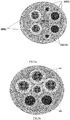
- Fig. 2 is a schematic structural diagram showing an example of a composite cable according to an embodiment of the present disclosure.
- the second wire assembly 102 includes wire(s) 1 and wire(s) 2, which are a fire wire and a zero line, respectively.
- the fire wire and zero line are both surrounded by an insulating layer 103.
- the insulating layer may be made of insulating material such as polyvinyl chloride (PVC) and may have one or more layers, such as two layers.
- the first wire assembly 101 may include a plurality of wires, such as 10 wires (numbered with "3" to "12"), or may include any other number of wires as needed.
- the plurality of wires may include wire(s) 3, wire(s) 4,wire(s) 5 and wire(s) 6 whose cores may be made of, for instance, pure copper, and the wire(s) 3, wire(s) 4,wire(s) 5 and wire(s) 6 may be surrounded, respectively, by a metal material layer for shield, such as an aluminum foil 201.
- the aluminum foil 201 may be connected to the cores 202 of the wires 3-6 for grounding.
- the aluminum foil 201 may be replaced with the above shield that contains different kinds of metal wires.
- the cores of the wires 3, 4, 5 and 6 may be, for instance, a positive signal line and a negative signal line respectively used to transmit a differential signal, and a ground core.
- the present disclosure is not limited thereto.
- the types of the cores may be decided in light of actual signal-transmission requirements.
- the plurality of wires may include wire(s) 7 and wire(s) 8, whose cores may be made of, for instance, pure copper.
- the wire(s) 7 and wire(s) 8 may be, for instance, a ground core and a DC power supply wire, respectively.
- Each of the wire(s) 7 and wire(s) 8 may be formed by twisting several wire cores, for instance, each of the wire(s) 7 and wire(s) 8 may be a twisted pair or a qudraplex, so as to reduce the electromagnetic interference effectively.
- the plurality of signal wires may further include wire(s) 9, wire(s) 10, wire(s) 11 and wire(s) 12, whose cores are made of tinned copper.
- the wire(s) 9, wire(s) 10, wire(s) 11 and wire(s) 12 may be used to transmit any signal including a user-defined signal.
- the wires 3-12 as a whole may be externally surrounded by the shield 105 that contains different kinds of metal wires, so as to be shielded from the outside.
- the wires 1-12 as a whole may be externally surrounded by the sheath 104 made of, for instance, PVC VW-1 for insulation and fire resistance.
- Fig. 2 only shows one example of the composite cable.
- the specific structure, material, function or the like of the composite cable can be designed by a person skilled in the art in light of actual needs, provided that the composite cable satisfies the user's requirements for transmitting signal.
- the metal wires contained in the shield 105 may include different kinds of metal wires with shielding capabilities for different physical fields, such as electric-shielding metal wires for an electric field (e.g., copper wires) and magnetic-shielding metal wires for a magnetic field (e.g., iron wires).
- electric-shielding metal wires for an electric field e.g., copper wires
- magnetic-shielding metal wires for a magnetic field e.g., iron wires.
- the present disclosure meets a number of aspects of shielding requirements, including both magnetic-shielding requirement and electric-shielding requirement.
- the metal wires selected as above are merely examples. And a person skilled in the art can decide, depending on actual needs, how many kinds of and what kinds of metal wires are to be selected, and what proportion each of the selected metal wires accounts for, provided that the selected metal wires can meet shielding requirements for different physical fields.
- the shield 105 may be formed with a netlike structure which is woven from a wire harness formed by different kinds of metal wires.
- the present disclosure is not meant to place any particular restrictions on the proportion of each kind of metal wires in the wire harness or the weaving method of the wire harness. They can be decided by a person skilled in the art in light of shielding requirements, costs or other factors. For instance, when the shield needs to have a higher shielding capability for a particular physical field, a possible approach is to increase the proportion of a metal wire that has excellent shielding performance for the particular physical field.
- Fig. 3 and Fig. 4 are schematic diagrams showing an exemplary wire harness and an exemplary netlike structure of a shield.
- a wire harness that is formed by combining a number of copper wires (represented by the solid lines) with the same number (or different number as needed) of iron wires (represented by the dashed lines).
- the resultant wire harnesses are woven into a netlike structure. Juxtaposition, twist or any other proper method may be used to form the wire harness.
- the shield 105 may be a netlike structure with, for example, prism, rectangle or square meshes, that is formed by alternatingly weaving two groups of parallel wire harness.
- Fig. 4 illustrates a possible weaving method.
- the shield 105 may be formed by winding a wire harness that is formed by juxtaposing different kinds of metal wires in a transverse direction.
- this embodiment provides a solution: dividing the first wire assembly into a plurality of first wire sub-assemblies, dividing the second wire assembly into a plurality of wires, and arranging the first wire sub-assemblies and the wires in such a way that they match each other in shape and location to such an extent that the interior of the cable is sufficiently filled by them.
- Figs. 5a-5g are structural diagrams showing examples of a composite cable according to an embodiment of the present disclosure.
- the first wire assembly may include at least two first wire sub-assemblies 1011, as shown in Figs. 5a, 5b , 5c , 5f and 5g .
- each of them may be surrounded by a sub-shield.
- the sub-shield may be the above shield, which is made of different kinds of metals, or a shield made of a single metal, e.g., aluminum foil. It is also possible that outside all the first wire sub-assemblies is surrounded by a shield made of different kinds of metals.
- the second wire assembly may comprise at least two wires 1021 each of which may be externally surrounded by an insulating layer, as shown in Figs. 5a-5g .
- wires 1021 1021a represents a fire wire
- 1021b represents a zero line.
- There may be one or more fire wires 1021a and one or more zero lines 1021b.
- a wire harness formed by the first wire sub-assemblies and the wires in the second wire assembly has a cross section whose outline is symmetric with respect to a diameter of the composite cable, such as a polygon symmetric with respect to a diameter of the composite cable, as shown in Figs. 5a-5g .
- Fig. 5a Take Fig. 5a for example, two thick wires and two sub-assemblies are juxtaposed with gaps between them, and the gaps are filled with two thin wires, leading to an overall hexagonal outline.
- Fig. 5a Take Fig. 5a for example, two thick wires and two sub-assemblies are juxtaposed with gaps between them, and the gaps are filled with two thin wires, leading to an overall hexagonal outline.
- one thin sub-assembly is in the middle with three thick sub-assemblies and two wires of the same thickness surrounding the thin sub-assembly, leading to an overall pentagonal outline.
- two sub-assemblies and two wires are juxtaposed, leading to a quadrilateral outline.
- first and second wire assemblies are not limited to the above examples. And they can be arranged in any way, provided that they form a stable structure.
- a wire harness formed by the first wire sub-assemblies and wires in the second wire assembly may have a cross section whose outline is circular-like, as shown in Fig. 2 .
- the first wire assembly may be divided into a plurality of first wire sub-assemblies (see, for example, Figs. 5a, 5b , 5c , 5f and 5g ) in light of the function of signals to be submitted.
- the second wire assembly may be divided into a desired number of wires (see, for example, Figs.
- the first wire sub-assemblies may be of the same diameter or be different from each other in diameter
- a first wire sub-assembly and a wire may be of the same diameter or be different from each other in diameter
- the wires may be of the same diameter or be different from each other in diameter, depending on actual needs. That is, the first wire assembly may be divided into first wire sub-assemblies of different thicknesses (see, for example, Fig. 5b ), and the second wire assembly may be divided into wires of different thicknesses (see, for example, Figs.
- a first wire assembly 101 may be divided into a plurality of first wire sub-assemblies 1011 (see, for example, Figs. 5a, 5b , 5c , 5f and 5g ) that are used to fill the composite cable.
- the first wire sub-assemblies 1011 are smaller in diameter and thus can be located more flexibly, so they enable the outer diameter of the composite cable to be smaller and be filled more sufficiently and thus improve the composite cable's stability.
- Fig. 5c for example, in Fig. 5c , two sub-assemblies of the same thickness and two wires of the same thickness are juxtaposed to form a quadrilateral outline.
- the first wire assembly 101 is functionally divided into two sub-assemblies 1011, one of which serves to transmit an HDMI-compatible signal or any other signal as needed, and the other serves to transmit a control signal or any other signal as needed.
- a second wire assembly 102 may be divided into, for instance, a plurality of wires 1021 (see, for example, Figs. 5a and 5d ) that are used to fill the composite cable. Likewise, those wires enable the composite cable to be smaller in diameter and be more stable.
- Either or both of the first wire assembly and the second wire assembly may be divided in any way by a person skilled in the art depending on actual needs, provided that the dividing way effects a stable composite cable.
- the composite cable according to examples of the present disclosure is excellent in shielding performance for different requirements.
Landscapes
- Physics & Mathematics (AREA)
- Electromagnetism (AREA)
- Engineering & Computer Science (AREA)
- Manufacturing & Machinery (AREA)
- Insulated Conductors (AREA)
- Communication Cables (AREA)
Applications Claiming Priority (2)
| Application Number | Priority Date | Filing Date | Title |
|---|---|---|---|
| CN201610127713.3A CN105788710B (zh) | 2016-03-07 | 2016-03-07 | 一种复合线缆 |
| PCT/CN2016/098665 WO2017152610A1 (zh) | 2016-03-07 | 2016-09-12 | 复合线缆 |
Publications (2)
| Publication Number | Publication Date |
|---|---|
| EP3285265A1 true EP3285265A1 (de) | 2018-02-21 |
| EP3285265A4 EP3285265A4 (de) | 2018-05-30 |
Family
ID=56386571
Family Applications (1)
| Application Number | Title | Priority Date | Filing Date |
|---|---|---|---|
| EP16893255.6A Withdrawn EP3285265A4 (de) | 2016-03-07 | 2016-09-12 | Verbundkabel |
Country Status (6)
| Country | Link |
|---|---|
| US (1) | US10446292B2 (de) |
| EP (1) | EP3285265A4 (de) |
| JP (1) | JP6511198B2 (de) |
| KR (1) | KR101976338B1 (de) |
| CN (1) | CN105788710B (de) |
| WO (1) | WO2017152610A1 (de) |
Families Citing this family (8)
| Publication number | Priority date | Publication date | Assignee | Title |
|---|---|---|---|---|
| RU2749866C2 (ru) * | 2016-03-04 | 2021-06-17 | Хэмпиджан Хф. | Кабель сонара верхней подборы высокого разрешения |
| CN105788710B (zh) | 2016-03-07 | 2018-05-08 | 合一智能科技(深圳)有限公司 | 一种复合线缆 |
| CN106961541A (zh) * | 2017-04-07 | 2017-07-18 | 信利光电股份有限公司 | 一种摄像装置 |
| JP7042418B2 (ja) * | 2018-09-26 | 2022-03-28 | 住友電装株式会社 | 配線部材 |
| JP7684048B2 (ja) * | 2021-01-15 | 2025-05-27 | Hoya株式会社 | 内視鏡、及び内視鏡システム |
| CN116564584A (zh) * | 2022-01-27 | 2023-08-08 | 北京字跳网络技术有限公司 | 一种线束及头戴设备 |
| DE102022201305A1 (de) | 2022-02-08 | 2022-12-01 | Carl Zeiss Smt Gmbh | Kabel zur anwendung in vakuumumgebungen und duv / euv-projektionsbelichtungsanlagen und entsprechende projektionsbelichtungsanlagen |
| CN120895329B (zh) * | 2025-09-30 | 2025-12-02 | 远东电缆有限公司 | 一种基于模态隔离的智能复合电缆及其制备方法 |
Family Cites Families (27)
| Publication number | Priority date | Publication date | Assignee | Title |
|---|---|---|---|---|
| GB502122A (en) | 1937-10-19 | 1939-03-13 | Western Electric Co | Improvements in electric cables having shielded conductors |
| US3215768A (en) * | 1963-09-23 | 1965-11-02 | Northrop Corp | Flexible wire and cable shielding |
| US3594491A (en) | 1969-06-26 | 1971-07-20 | Tektronix Inc | Shielded cable having auxiliary signal conductors formed integral with shield |
| JPS5019730A (de) | 1973-06-26 | 1975-03-01 | ||
| US4641110A (en) * | 1984-06-13 | 1987-02-03 | Adams-Russell Company, Inc. | Shielded radio frequency transmission cable having propagation constant enhancing means |
| JPH0660730A (ja) * | 1992-08-06 | 1994-03-04 | Sumitomo Wiring Syst Ltd | 大電流用遮蔽ケーブル |
| JP3195066B2 (ja) | 1992-09-18 | 2001-08-06 | 株式会社東芝 | ドライエッチング方法 |
| US5956445A (en) * | 1994-05-20 | 1999-09-21 | Belden Wire & Cable Company | Plenum rated cables and shielding tape |
| JP3871886B2 (ja) | 2001-01-19 | 2007-01-24 | 沖電線株式会社 | 広帯域シールド複合ケーブル |
| DE10162739A1 (de) * | 2001-12-20 | 2003-07-03 | Nexans | Flexible elektrische Leitung |
| US6844500B2 (en) | 2002-01-07 | 2005-01-18 | Conectl Corporation | Communications cable and method for making same |
| JP2006331758A (ja) * | 2005-05-25 | 2006-12-07 | Yazaki Corp | 電磁遮蔽ケーブル |
| JP5019730B2 (ja) | 2005-08-23 | 2012-09-05 | 株式会社オートネットワーク技術研究所 | シールドケーブルとシールド用複合素線 |
| CN200983281Y (zh) * | 2006-11-20 | 2007-11-28 | 深圳市华灿电子科技发展有限公司 | 数据电源复合电缆 |
| US8076580B2 (en) * | 2009-06-08 | 2011-12-13 | CareFusion 209, Inc. | Cable for enhancing biopotential measurements and method of assembling the same |
| CN201489867U (zh) * | 2009-08-25 | 2010-05-26 | 安徽华电线缆集团有限公司 | 一种耐高温屏蔽电缆 |
| CN102097161B (zh) | 2010-12-24 | 2013-01-23 | 江苏远洋东泽电缆股份有限公司 | 船舰海工闭路电视摄像机用电缆及其制造方法 |
| CN202189598U (zh) * | 2011-07-06 | 2012-04-11 | 朗诗德电气有限公司 | 带有屏蔽功能的多芯复合线缆 |
| JP2014017084A (ja) * | 2012-07-06 | 2014-01-30 | Sumitomo Electric Ind Ltd | 多芯ケーブル |
| CN202771817U (zh) * | 2012-08-16 | 2013-03-06 | 兴乐电缆有限公司 | 中压抗干扰煤矿用采煤机软电缆 |
| JP5761226B2 (ja) * | 2013-02-22 | 2015-08-12 | 住友電気工業株式会社 | 多芯ケーブルおよびその製造方法 |
| JP6044498B2 (ja) * | 2013-09-26 | 2016-12-14 | 日立金属株式会社 | 電気ケーブル |
| CN204102593U (zh) * | 2014-07-18 | 2015-01-14 | 东莞讯滔电子有限公司 | 线缆 |
| CN204010758U (zh) * | 2014-08-29 | 2014-12-10 | 惠州市德胜电线有限公司 | 一种用于高频数据传输的抗弯折电缆 |
| CN104392796A (zh) * | 2014-12-02 | 2015-03-04 | 安徽渡江电缆集团有限公司 | 一种紧凑型抗干扰综合电缆 |
| US9508467B2 (en) * | 2015-01-30 | 2016-11-29 | Yfc-Boneagle Electric Co., Ltd. | Cable for integrated data transmission and power supply |
| CN105788710B (zh) * | 2016-03-07 | 2018-05-08 | 合一智能科技(深圳)有限公司 | 一种复合线缆 |
-
2016
- 2016-03-07 CN CN201610127713.3A patent/CN105788710B/zh active Active
- 2016-09-12 JP JP2018531097A patent/JP6511198B2/ja not_active Expired - Fee Related
- 2016-09-12 EP EP16893255.6A patent/EP3285265A4/de not_active Withdrawn
- 2016-09-12 US US15/752,712 patent/US10446292B2/en active Active
- 2016-09-12 WO PCT/CN2016/098665 patent/WO2017152610A1/zh not_active Ceased
- 2016-09-12 KR KR1020187014802A patent/KR101976338B1/ko not_active Expired - Fee Related
Also Published As
| Publication number | Publication date |
|---|---|
| JP6511198B2 (ja) | 2019-05-15 |
| KR101976338B1 (ko) | 2019-05-07 |
| JP2019500727A (ja) | 2019-01-10 |
| KR20180067688A (ko) | 2018-06-20 |
| US10446292B2 (en) | 2019-10-15 |
| WO2017152610A1 (zh) | 2017-09-14 |
| US20180240571A1 (en) | 2018-08-23 |
| CN105788710A (zh) | 2016-07-20 |
| CN105788710B (zh) | 2018-05-08 |
| EP3285265A4 (de) | 2018-05-30 |
Similar Documents
| Publication | Publication Date | Title |
|---|---|---|
| US10446292B2 (en) | Composite cable | |
| US9934888B2 (en) | Cable for differential serial transmission | |
| EP3178094B1 (de) | Elektrodraht | |
| TWI834631B (zh) | 遮罩層及設有該遮罩層之線纜 | |
| CN105321600A (zh) | 一种抗拉耐压矿用自散热电缆 | |
| CN206546724U (zh) | 一种数控机床拖链系统专用高柔性控制电缆 | |
| CN203536085U (zh) | 一种七芯测磁电缆 | |
| CN203644459U (zh) | 铝合金阻燃变频电缆 | |
| CN203503381U (zh) | 一种绝缘屏蔽控制电缆 | |
| CN208189251U (zh) | 一种防干扰型汽车用电缆 | |
| CN203150176U (zh) | 抗紫外线综合电缆 | |
| CN206584760U (zh) | 一种高强度屏蔽型电缆 | |
| CN222636886U (zh) | 通讯线缆及用电设备 | |
| CN219832284U (zh) | 一种抗电磁特种综合电缆 | |
| CN215815233U (zh) | 一种新能源设备用氧化镁矿物绝缘电缆 | |
| CN216528070U (zh) | 一种并排线材 | |
| CN214253969U (zh) | 一种高屏蔽高效紧凑绝缘电缆 | |
| CN202887779U (zh) | 综合屏蔽控制电缆 | |
| CN107591223A (zh) | 一种用于航空航天的高性能电缆 | |
| CN202230770U (zh) | 船用综合特种电缆 | |
| CN206401041U (zh) | 耐火型通讯系统综合布线专用光缆 | |
| CN208477998U (zh) | 一种阻燃耐腐防水计算机电缆 | |
| CN205487400U (zh) | 一种高抗拉高温计算机屏蔽电缆 | |
| CN108962467A (zh) | 一种船用通信电缆 | |
| CN208538525U (zh) | 一种高强度抗电磁干扰混合型电缆 |
Legal Events
| Date | Code | Title | Description |
|---|---|---|---|
| PUAI | Public reference made under article 153(3) epc to a published international application that has entered the european phase |
Free format text: ORIGINAL CODE: 0009012 |
|
| 17P | Request for examination filed |
Effective date: 20171116 |
|
| AK | Designated contracting states |
Kind code of ref document: A1 Designated state(s): AL AT BE BG CH CY CZ DE DK EE ES FI FR GB GR HR HU IE IS IT LI LT LU LV MC MK MT NL NO PL PT RO RS SE SI SK SM TR |
|
| AX | Request for extension of the european patent |
Extension state: BA ME |
|
| A4 | Supplementary search report drawn up and despatched |
Effective date: 20180502 |
|
| RIC1 | Information provided on ipc code assigned before grant |
Ipc: H01B 11/10 20060101ALI20180423BHEP Ipc: H01B 11/06 20060101AFI20180423BHEP Ipc: H01B 13/26 20060101ALN20180423BHEP |
|
| 17Q | First examination report despatched |
Effective date: 20190213 |
|
| DAV | Request for validation of the european patent (deleted) | ||
| DAX | Request for extension of the european patent (deleted) | ||
| STAA | Information on the status of an ep patent application or granted ep patent |
Free format text: STATUS: THE APPLICATION IS DEEMED TO BE WITHDRAWN |
|
| 18D | Application deemed to be withdrawn |
Effective date: 20200819 |