EP3285017B1 - Heating and cooling sail with at least one ventilator - Google Patents
Heating and cooling sail with at least one ventilator Download PDFInfo
- Publication number
- EP3285017B1 EP3285017B1 EP17171042.9A EP17171042A EP3285017B1 EP 3285017 B1 EP3285017 B1 EP 3285017B1 EP 17171042 A EP17171042 A EP 17171042A EP 3285017 B1 EP3285017 B1 EP 3285017B1
- Authority
- EP
- European Patent Office
- Prior art keywords
- heating
- fan
- support plate
- cooling
- panel according
- Prior art date
- Legal status (The legal status is an assumption and is not a legal conclusion. Google has not performed a legal analysis and makes no representation as to the accuracy of the status listed.)
- Active
Links
- 238000001816 cooling Methods 0.000 title claims description 62
- 238000010438 heat treatment Methods 0.000 title claims description 42
- 239000012530 fluid Substances 0.000 claims description 4
- 238000011144 upstream manufacturing Methods 0.000 claims 1
- 239000003570 air Substances 0.000 description 50
- 238000009423 ventilation Methods 0.000 description 8
- 230000000694 effects Effects 0.000 description 7
- XLYOFNOQVPJJNP-UHFFFAOYSA-N water Substances O XLYOFNOQVPJJNP-UHFFFAOYSA-N 0.000 description 3
- 238000004378 air conditioning Methods 0.000 description 2
- 238000007664 blowing Methods 0.000 description 2
- 239000002826 coolant Substances 0.000 description 2
- 238000009413 insulation Methods 0.000 description 2
- 238000004026 adhesive bonding Methods 0.000 description 1
- 239000012080 ambient air Substances 0.000 description 1
- 230000015572 biosynthetic process Effects 0.000 description 1
- 230000005494 condensation Effects 0.000 description 1
- 238000009833 condensation Methods 0.000 description 1
- 239000000110 cooling liquid Substances 0.000 description 1
- 239000013529 heat transfer fluid Substances 0.000 description 1
- 238000009434 installation Methods 0.000 description 1
- 239000000463 material Substances 0.000 description 1
- 239000002184 metal Substances 0.000 description 1
- 230000035515 penetration Effects 0.000 description 1
- 230000008092 positive effect Effects 0.000 description 1
- 238000009420 retrofitting Methods 0.000 description 1
- 230000000630 rising effect Effects 0.000 description 1
- 238000000926 separation method Methods 0.000 description 1
- 238000005476 soldering Methods 0.000 description 1
- 239000000725 suspension Substances 0.000 description 1
- 238000003466 welding Methods 0.000 description 1
Images
Classifications
-
- F—MECHANICAL ENGINEERING; LIGHTING; HEATING; WEAPONS; BLASTING
- F24—HEATING; RANGES; VENTILATING
- F24F—AIR-CONDITIONING; AIR-HUMIDIFICATION; VENTILATION; USE OF AIR CURRENTS FOR SCREENING
- F24F13/00—Details common to, or for air-conditioning, air-humidification, ventilation or use of air currents for screening
- F24F13/02—Ducting arrangements
- F24F13/06—Outlets for directing or distributing air into rooms or spaces, e.g. ceiling air diffuser
- F24F13/072—Outlets for directing or distributing air into rooms or spaces, e.g. ceiling air diffuser of elongated shape, e.g. between ceiling panels
-
- F—MECHANICAL ENGINEERING; LIGHTING; HEATING; WEAPONS; BLASTING
- F24—HEATING; RANGES; VENTILATING
- F24F—AIR-CONDITIONING; AIR-HUMIDIFICATION; VENTILATION; USE OF AIR CURRENTS FOR SCREENING
- F24F13/00—Details common to, or for air-conditioning, air-humidification, ventilation or use of air currents for screening
- F24F13/08—Air-flow control members, e.g. louvres, grilles, flaps or guide plates
-
- F—MECHANICAL ENGINEERING; LIGHTING; HEATING; WEAPONS; BLASTING
- F24—HEATING; RANGES; VENTILATING
- F24F—AIR-CONDITIONING; AIR-HUMIDIFICATION; VENTILATION; USE OF AIR CURRENTS FOR SCREENING
- F24F13/00—Details common to, or for air-conditioning, air-humidification, ventilation or use of air currents for screening
- F24F13/26—Arrangements for air-circulation by means of induction, e.g. by fluid coupling or thermal effect
-
- F—MECHANICAL ENGINEERING; LIGHTING; HEATING; WEAPONS; BLASTING
- F24—HEATING; RANGES; VENTILATING
- F24F—AIR-CONDITIONING; AIR-HUMIDIFICATION; VENTILATION; USE OF AIR CURRENTS FOR SCREENING
- F24F5/00—Air-conditioning systems or apparatus not covered by F24F1/00 or F24F3/00, e.g. using solar heat or combined with household units such as an oven or water heater
- F24F5/0089—Systems using radiation from walls or panels
Definitions
- the invention relates to a heating and cooling sail, comprising at least one support plate and channels connected to it in a heat-conducting manner, through which a fluid can flow, and at least one fan with an air outlet surface.
- Cooling sails have been known from the state of the art for some time and are used to dissipate room heat. This is done via the pipes connected to the support plate in a heat-conducting manner, through which water typically flows as a heat transfer medium, with the warm rising room air giving off its heat to the cool water.
- Cooling sails are often combined with ventilation systems because, in the case of cooling, it is necessary to limit the room humidity to avoid condensation.
- the airflow to the cooling sails is also influenced by the ventilation systems.
- the ventilation systems can, for example, include source outlets on the floor, on the wall or on the ceiling.
- Heating and cooling sails without a connected ventilation system are a system that works purely passively. When cooling occurs, warm room air rises and reaches the sail, where the heat is transferred to the cool fluid carried in the channels. However, the cool air often accumulates above the sail, reducing the cooling effect. When heated, the heat accumulates under the sail, limiting the effectiveness of passive sails.
- the known device has a housing with a front wall and a rear wall, an interior of the housing being fed with supply air from an air conditioning system. Peltier elements are arranged in the interior of the housing to cool the supply air.
- WO 2011/091886 A1 describes a ceiling sail with an air outlet, whereby the supply air is deflected by approximately 180° from its introduction into the air outlet to its exit. Flow over the carrier plate occurs via nozzles.
- the present invention there is a division of the total volume flow leaving the air outlet surface of the fan, which in the case of cooling has the effect that the cool air accumulating above the support plate is actively moved into the room, whereby the cooling effect can be significantly increased.
- the partial volume flow that runs below the support plate is led directly into the room, which creates the impression of a fresh air supply due to the air movement.
- the mere fact that both sides of the carrier plate are actively flowed over is advantageous, as this per se increases heat transfer and thus increases the performance of the heating and cooling sail.
- the guide element is arranged in an area “in front of” the air outlet surface is to be understood as meaning that the guide element is positioned outside the fan.
- the guide element is located behind the air outlet surface when viewed in the direction of flow, so that the air leaving the fan first passes the air outlet surface before it reaches the guide element.
- the division of the total volume flow leaving the fan causes the warm air accumulating below the support plate to be actively brought back into the room, which strengthens the heating effect and increases the penetration depth of the warm air towards the floor of the room.
- the formation of a temperature layer is prevented even without the arrangement of nozzles and an evenly mixed room air is created.
- the fan is advantageously a free-blowing fan without a housing, so that the overall height of the heating and cooling sail according to the invention remains small. Since the fan is not connected to a primary air supply, it is a pure recirculation system, but is actively operated. The arrangement of the guide element and the resulting subdivision of the volume flow leaving the fan creates a heating and cooling sail with variable application options, which is also characterized by low power consumption and good acoustic properties, since fans with a low pressure increase can be used.
- the fan is equipped with channels which, starting from the fan, lead to the respective guide element or elements of the individual carrier plates.
- the air outlet surface of the fan is thus formed by the individual air outlet surfaces of the channels ending in front of the guide element.
- the guide element can be designed as a simple sheet metal or, for example, as a so-called scoop plate, whereby it can be connected to the carrier plate.
- the guide element and carrier plate can be connected by gluing, welding, soldering, screwing or in another way.
- the guide element can also be positioned using other means and can be at a distance from the carrier plate.
- the width of the guide element should be at least or exactly the width of the air outlet cross section of the fan or all fans.
- the guide element can also be made of plastic or other materials.
- the distribution of the total volume flow leaving the air outlet surface can be influenced in such a way that the distribution is influenced by the height up to which the guide element protrudes in relation to the height of the air outlet surface. If the guide element extends exactly to half the height of the air outlet surface, then - assuming equal resistance in both flow paths - there is an exact division of the total volume flow into two equal partial volume flows. Otherwise, the partial volume flows are of different sizes, with the resistances in the respective flow paths also having an influence on the distribution.
- the distance between an edge of the guide element facing the air outlet surface and the air outlet surface is chosen to be as small as possible. Accordingly, it is conceivable that the guide element is directly adjacent to the air outlet surface and therefore there is a distance of 0 mm. In this case, there is an immediate separation of the total volume flow and the partial volume flow flowing under the carrier plate is optimally guided. If the distance is chosen to be too large, there is a risk that the partial volume flow intended for flow below the carrier plate will not be guided to a sufficient extent and will only partially reach under the carrier plate. In order not to jeopardize the positive effect of the air guidance, the distance should be less than or equal to 200 mm, advantageously less than 100 mm, but better less than 50 mm, more advantageously less than 20 mm.
- the fan or fans is arranged with a support surface on the support plate, so that the air outlet surface of the fan or fans is located overall above the support plate.
- the carrier plate itself is sufficiently stable and also sufficiently stable connected to the ceiling, in particular suspended, so that the fan can come to rest on the carrier plate without having to be separately attached to the ceiling.
- the carrier plate In order to ensure that the partial volume flow emerging from the air outlet cross section below the guide element flows to the underside of the carrier plate, the carrier plate must be at least partially perforated or have an opening, preferably in an area of a projection of the guide element. In this way, the partial volume flow guided below the guide element reaches the underside of the carrier plate via the perforations or the opening and flows along it.
- the guide element is adjustable with regard to the angle that it forms with the air outlet surface of the fan.
- the entire volume flow can be divided into different partial volume flows, resulting in different cooling effects or heating effects.
- the adjustment can be done using a lockable or motor-operated holding element, so that the sail can be individually adapted to a space or load situation.
- the carrier plate has perforations or holes, which preferably define a free cross section of approximately 10% to 30% of the perforated or holed total area. The entire visible surface or only part of it can be perforated. Furthermore, with regard to acoustics, it can be useful or helpful to provide sound-absorbing elements on or above the support plate. In this way, increased requirements regarding sound insulation can be met. Here It must be structurally ensured that heat transfer from the top of the carrier plate to the ambient air is possible.
- a particularly preferred embodiment of the invention provides that the at least one fan is a fan with a low pressure increase, which is characterized in that it promotes a high volume flow with very little noise.
- the power consumption is also very low.
- a cross-flow fan can be used.
- Another advantage that results from the aforementioned feature is the very low possible overall height that the heating and cooling sail according to the invention has.
- the overall height of the fan should be between 20 and 80 mm, which results in an overall overall height of the cooling sail of virtually the same size.
- the at least one fan is equipped with a speed control. This allows the cooling or heating output of the heating and cooling sail to be varied, which is useful in terms of individual adjustability by the user and thus comfort.
- At least one cooling register is arranged on the carrier plate in addition to the channels for the heat transfer fluid, an increase in the cooling capacity is made possible and the cooling sail according to the invention can also be used in rooms with high cooling loads.
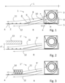
- a heating and cooling sail 1 is shown, which is composed of a carrier plate 2 with a length L and a width and a fan 3 arranged on the carrier plate 2. Since a vertical section is shown, the width of the carrier plate 2 cannot be seen. Typically, heating and cooling sails vary in width between 0.6 m and 1.2 m. However, other widths are of course conceivable.
- the length L of the carrier plate 2 is also in the Figure 1 only indicated, since the heating and cooling sail 1 is not shown in its full length L.
- the length of heating and cooling sails is also individual and can be between 1 m and 4 m.
- the carrier plate 2 is provided with meandering channels 4 in which cooling liquid, such as water, is circulated. The carrier plate 2 and the channels 4 are connected to one another in a heat-conducting manner.
- the fan 3 is a free-blowing fan 3 that has no housing and sucks in room air. Accordingly, it is not connected to a ventilation system, so that the heating and cooling sail 1 according to the invention generates an active recirculation mode.
- the fan 3 is arranged with a support surface 5 on the support plate 2 and is not in contact with it Figure 1 Fasteners shown connected.
- the support plate 2 is attached to a ceiling (not shown in the figure) by suspension, as is usual in the prior art, and is in the Figure 1 also not shown. According to the Figure 1 the fan 3 is arranged at a right end of the support plate 2, i.e. on a short side, the support plate 2 having an upstand 6 along this short side.
- the fan 3 has an air outlet surface 7 from which previously sucked room air flows out again.
- a guide element 9 is arranged, which runs transversely to the air outlet surface 7 and forms an angle ⁇ of approximately 80 ° with the air outlet surface 7. Accordingly, an angle ⁇ between the carrier plate 2 and the guide element 9 is 20°.
- a distance a between an edge 10 of the guide element 9 facing the fan 3 and the air outlet surface 7 of the fan 3 is 20 mm.
- the guide element 9 is firmly connected to the support plate 2 at its edge 10 'facing away from the fan 3, for example via a weld seam, and is therefore not adjustable with regard to the aforementioned angles ⁇ and ⁇ .
- the arrangement of the guide element 9 causes a volume flow leaving the air outlet surface 7 of the fan 3 to be divided into two partial volume flows, which are indicated in the figure by two arrows 11, 12, with a first, upper partial volume flow (arrow 11) flows above the carrier plate 2 and a second, lower partial volume flow (arrow 12) flows below the carrier plate 2.
- both sides of the carrier plate 2 are actively ventilated, thereby optimizing heat transfer for cooling or heating.
- the upper partial volume flow (arrow 11) is guided along the channels 4 containing cool fluid, whereby the heat of the upper partial volume flow (arrow 11) is released to the coolant.
- the carrier plate 2 is perforated in an area of a projection P of the guide element 9.
- the carrier plate as a whole can also be provided with a perforation.
- both the carrier plate 2 and the guide element 9 have a width that corresponds at least to the width of the three fans 3 located next to one another.
- the heating and cooling sail 1 ' shown points to the heating and cooling sail 1 Figure 1
- a sound-absorbing element 13 in the form of an acoustic mat is arranged above the support plate 2, so that higher demands on sound insulation can be achieved.
- the acoustic mat is located at a distance a' from the carrier plate 2 and can, for example, be attached to a ceiling, not shown.
- acoustic elements can also be arranged directly on the carrier plate 2, whereby these are advantageously only arranged in the area outside the channels 4.
- the guide element 9 ' according to Figure 2 is not firmly connected to the carrier plate 2 and is adjustable with regard to the angle ⁇ . This can influence the alignment of the partial volume flows (arrows 11, 12) and ultimately also the air conditioning of the room R.
- FIG. 3 an alternative heating and cooling sail 1" is shown, with a cooling register 14 being arranged on the carrier plate 2 in addition to the channels 4. This allows the temperature control of the upper partial volume flow (arrow 11) to be carried out more intensively.
Description
Die Erfindung betrifft ein Heiz- und Kühlsegel, umfassend mindestens eine Trägerplatte und damit wärmeleitend verbundene Kanäle, die mit einem Fluid durchströmbar sind, sowie mindestens einen Ventilator mit einer Luftaustrittsfläche.The invention relates to a heating and cooling sail, comprising at least one support plate and channels connected to it in a heat-conducting manner, through which a fluid can flow, and at least one fan with an air outlet surface.
Kühlsegel sind bereits seit geraumer Zeit aus dem Stand der Technik bekannt und werden dazu genutzt, Raumwärme abzuführen. Dies erfolgt über die mit der Trägerplatte wärmeleitend verbundenen Rohre, die typischerweise mit Wasser als Wärmeträgermedium durchströmt werden, wobei die warme aufsteigende Raumluft ihre Wärme an das kühle Wasser abgibt.Cooling sails have been known from the state of the art for some time and are used to dissipate room heat. This is done via the pipes connected to the support plate in a heat-conducting manner, through which water typically flows as a heat transfer medium, with the warm rising room air giving off its heat to the cool water.
Oftmals werden Kühlsegel mit Lüftungsanlagen kombiniert, da im Kühlfall eine Begrenzung der Raumfeuchte zur Vermeidung von Kondensation notwendig ist. Darüber hinaus wird über die Lüftungsanlagen auch das Anströmen der Kühlsegel beeinflusst. Dabei können die Lüftungsanlagen beispielsweise Quellauslässe am Boden, an der Wand oder an der Decke umfassen.Cooling sails are often combined with ventilation systems because, in the case of cooling, it is necessary to limit the room humidity to avoid condensation. In addition, the airflow to the cooling sails is also influenced by the ventilation systems. The ventilation systems can, for example, include source outlets on the floor, on the wall or on the ceiling.
Allerdings ist die Verwendung eines Heiz- und Kühlsegels auch in Räumen ohne Lüftungsanlagen möglich, insbesondere wenn Kühlsegel nachträglich in Räumen installiert werden sollen, die nicht über eine Lüftungsanlage verfügen und die Nachrüstung einer solchen aus Kostengründen nicht in Frage kommt. Die notwendige Frischluftzufuhr muss dann durch klassische Fensterlüftung erfolgen.However, the use of a heating and cooling sail is also possible in rooms without ventilation systems, especially if cooling sails are to be subsequently installed in rooms that do not have a ventilation system and retrofitting one is out of the question for cost reasons. The necessary supply of fresh air must then be provided through classic window ventilation.
Bei Heiz- und Kühlsegeln ohne angeschlossene Lüftungsanlage handelt es sich um ein System, das rein passiv arbeitet. Im Kühlfall steigt warme Raumluft nach oben und gelangt an das Segel, wo die Wärme an das in den Kanälen geführte kühle Fluid abgegeben wird. Hier staut sich jedoch die kühle Luft oftmals oberhalb des Segels, so dass der Kühleffekt vermindert wird. Im Heizfall staut sich die Wärme unter dem Segel, so dass die Wirksamkeit passiver Segel eingeschränkt ist.Heating and cooling sails without a connected ventilation system are a system that works purely passively. When cooling occurs, warm room air rises and reaches the sail, where the heat is transferred to the cool fluid carried in the channels. However, the cool air often accumulates above the sail, reducing the cooling effect. When heated, the heat accumulates under the sail, limiting the effectiveness of passive sails.
Um den Kühlungseffekt bei einem reinen passiven System zu unterstützen, ist es möglich, einen Ventilator auf dem Kühlsegel vorzusehen. Hierdurch erhält man ein aktives Umluftsystem. Je nach Anordnung des Ventilators profitiert davon entweder der Heiz- oder der Kühlfall.To support the cooling effect in a purely passive system, it is possible to provide a fan on the cooling sail. This creates an active air circulation system. Depending on the arrangement of the fan, either the heating or the cooling case benefits.
Aus dem Dokument
Das Dokument
Es ist Aufgabe der vorliegenden Erfindung, ein Heiz- und Kühlsegel der eingangs genannten Art so weiterzuentwickeln, dass es sich hinsichtlich seiner Wirtschaftlichkeit und seiner akustischen Eigenschaften auszeichnet und dass es sowohl im Heiz- als auch im Kühlfall gleichermaßen vom Einsatz des Ventilators profitiert.It is the object of the present invention to further develop a heating and cooling sail of the type mentioned in such a way that it is distinguished in terms of its economic efficiency and its acoustic properties and that it benefits equally from the use of the fan in both heating and cooling cases.
Ausgehend von dem zu Anfang beschriebenen Heiz- und Kühlsegel wird die vorstehende Aufgabe durch ein Segel nach Anspruch 1 gelöst.Starting from the heating and cooling sail described at the beginning, the above task is solved by a sail according to
Gemäß der vorliegenden Erfindung liegt demnach eine Aufteilung des die Luftaustrittsfläche des Ventilators verlassenen Gesamtvolumenstroms vor, was im Kühlfall den Effekt hat, dass die sich stauende kühle Luft oberhalb der Trägerplatte aktiv in den Raum bewegt wird, wodurch der Kühleffekt deutlich gesteigert werden kann. Gleichzeitig wird der Teilvolumenstrom, der unterhalb der Trägerplatte verläuft, direkt in den Raum geführt, wodurch aufgrund der Luftbewegung der Eindruck einer Frischluftzufuhr entsteht. Darüber hinaus ist allein die Tatsache vorteilhaft, dass beide Seiten der Trägerplatte aktiv überströmt werden, da hierdurch per se eine erhöhte Wärmeübertragung stattfindet und die Leistung des Heiz- und Kühlsegels somit gesteigert wird.According to the present invention, there is a division of the total volume flow leaving the air outlet surface of the fan, which in the case of cooling has the effect that the cool air accumulating above the support plate is actively moved into the room, whereby the cooling effect can be significantly increased. At the same time, the partial volume flow that runs below the support plate is led directly into the room, which creates the impression of a fresh air supply due to the air movement. In addition, the mere fact that both sides of the carrier plate are actively flowed over is advantageous, as this per se increases heat transfer and thus increases the performance of the heating and cooling sail.
Dass das Leitelement in einem Bereich "vor" der Luftaustrittsfläche angeordnet ist, ist so zu verstehen, dass das Leitelement außerhalb des Ventilators positioniert ist. Anders ausgedrückt befindet sich das Leitelement in Strömungsrichtung betrachtet hinter der Luftaustrittsfläche, so dass die den Ventilator verlassende Luft zunächst die Luftaustrittsfläche passiert, bevor sie an das Leitelement gelangt.The fact that the guide element is arranged in an area “in front of” the air outlet surface is to be understood as meaning that the guide element is positioned outside the fan. In other words, the guide element is located behind the air outlet surface when viewed in the direction of flow, so that the air leaving the fan first passes the air outlet surface before it reaches the guide element.
Im Heizfall, also für den Fall, dass die Raumtemperatur geringer ist als die des "Kühlmediums" in den Kanälen, bewirkt die Aufteilung des den Ventilator verlassenen Gesamtvolumenstroms, dass die sich unterhalb der Trägerplatte stauende warme Luft aktiv wieder in den Raum gebracht wird, was den Heizeffekt verstärkt und die Eindringtiefe der Warmluft in Richtung auf den Boden des Raums erhöht. Die Bildung von einer Temperaturschicht wird auch ohne die Anordnung von Düsen verhindert und es entsteht eine gleichmäßig durchmischte Raumluft.In the case of heating, i.e. in the event that the room temperature is lower than that of the "cooling medium" in the ducts, the division of the total volume flow leaving the fan causes the warm air accumulating below the support plate to be actively brought back into the room, which strengthens the heating effect and increases the penetration depth of the warm air towards the floor of the room. The formation of a temperature layer is prevented even without the arrangement of nozzles and an evenly mixed room air is created.
Bei dem Ventilator handelt es sich vorteilhafterweise um einen frei blasenden Ventilator ohne Gehäuse, so dass die Bauhöhe des erfindungsgemäßen Heiz- und Kühlsegels klein bleibt. Da der Ventilator nicht an eine Primärluftversorgung angeschlossen ist, handelt es sich um ein reines Umluftsystem, das jedoch aktiv betrieben wird. Durch die Anordnung des Leitelements und die dadurch hervorgerufene Unterteilung des den Ventilator verlassenen Volumenstroms entsteht ein Heiz- und Kühlsegel mit variablen Einsatzmöglichkeiten, das sich ferner durch geringen Stromverbrauch und gute schalltechnische Eigenschaften auszeichnet, da Ventilatoren mit geringer Druckerhöhung eingesetzt werden können.The fan is advantageously a free-blowing fan without a housing, so that the overall height of the heating and cooling sail according to the invention remains small. Since the fan is not connected to a primary air supply, it is a pure recirculation system, but is actively operated. The arrangement of the guide element and the resulting subdivision of the volume flow leaving the fan creates a heating and cooling sail with variable application options, which is also characterized by low power consumption and good acoustic properties, since fans with a low pressure increase can be used.
Es versteht sich von selbst, dass in Abhängigkeit von der Breite des Heiz- und Kühlsegels mehrere Ventilatoren nebeneinander angeordnet werden können, um die vormals beschriebenen positiven Strömungsverhältnisse über die gesamte Breite des Segels zu erhalten.It goes without saying that, depending on the width of the heating and cooling sail, several fans can be arranged next to each other in order to maintain the previously described positive flow conditions over the entire width of the sail.
Andersherum ist es auch denkbar, dass lediglich ein Ventilator vorgesehen wird, der eine oder mehrere Trägerplatten anströmt. Hierzu wird der Ventilator mit Kanälen ausgestattet, die ausgehend von dem Ventilator zu dem oder den jeweiligen Leitelementen der einzelnen Trägerplatten führen. Somit wird die Luftaustrittsfläche des Ventilators durch die einzelnen Luftaustrittsflächen der vor dem Leitelement endenden Kanäle gebildet. (Anregung von Herrn Makulla)Conversely, it is also conceivable that only one fan is provided, which flows against one or more carrier plates. For this purpose, the fan is equipped with channels which, starting from the fan, lead to the respective guide element or elements of the individual carrier plates. The air outlet surface of the fan is thus formed by the individual air outlet surfaces of the channels ending in front of the guide element. (Suggestion from Mr Makulla)
Das Leitelement kann als einfaches Blech ausgebildet sein oder beispielsweise als sogenanntes Schöpfblech, wobei es mit der Trägerplatte verbunden sein kann. Eine Verbindung von Leitelement und Trägerplatte kann durch Kleben, Schweißen, Löten, Schrauben oder sonstige Weise erfolgen. Alternativ kann das Leitelement auch mit Hilfe anderer Mittel positioniert sein und kann einen Abstand zu der Trägerplatte aufweisen. Die Breite des Leitelements sollte mindestens oder genau der Breite des Luftaustrittsquerschnitts des Ventilators bzw. aller Ventilatoren entsprechen. Das Leitelement kann auch aus Kunststoff oder anderen Materialien gefertigt sein.The guide element can be designed as a simple sheet metal or, for example, as a so-called scoop plate, whereby it can be connected to the carrier plate. The guide element and carrier plate can be connected by gluing, welding, soldering, screwing or in another way. Alternatively, the guide element can also be positioned using other means and can be at a distance from the carrier plate. The width of the guide element should be at least or exactly the width of the air outlet cross section of the fan or all fans. The guide element can also be made of plastic or other materials.
Mit der Anordnung des Leitelements kann in Bezug auf die Aufteilung des die Luftaustrittsfläche verlassenden Gesamtvolumenstroms insofern Einfluss genommen werden, als dass die Aufteilung durch die Höhe beeinflusst wird, bis zu der das Leitelement in Bezug auf die Höhe der Luftaustrittsfläche ragt. Führt das Leitelement genau bis zur Hälfte der Höhe der Luftaustrittsfläche, so liegt - gleiche Widerstände in beiden Strömungswegen unterstellt - eine genaue Teilung des Gesamtvolumenstroms in zwei gleiche Teilvolumenströme vor. Andernfalls sind die Teilvolumenströme unterschiedlich groß, wobei die Widerstände in den jeweiligen Strömungswegen ebenfalls einen Einfluss auf die Aufteilung besitzen.With the arrangement of the guide element, the distribution of the total volume flow leaving the air outlet surface can be influenced in such a way that the distribution is influenced by the height up to which the guide element protrudes in relation to the height of the air outlet surface. If the guide element extends exactly to half the height of the air outlet surface, then - assuming equal resistance in both flow paths - there is an exact division of the total volume flow into two equal partial volume flows. Otherwise, the partial volume flows are of different sizes, with the resistances in the respective flow paths also having an influence on the distribution.
In Bezug auf die erfindungsgemäße Luftführung ist es ferner vorteilhaft, wenn der Abstand zwischen einem der Luftaustrittsfläche zugewandten Rand des Leitelements und der Luftaustrittsfläche so klein wie möglich gewählt ist. Dementsprechend ist es denkbar, dass das Leitelement direkt an die Luftaustrittsfläche angrenzt und somit ein Abstand von 0 mm vorliegt. In diesem Fall liegt eine sofortige Trennung des Gesamtvolumenstroms vor und der unter die Trägerplatte strömende Teilvolumenstrom wird optimal geführt. Ist der Abstand zu groß gewählt, besteht die Gefahr, dass der zur Strömung unterhalb der Trägerplatte vorgesehene Teilvolumenstrom nicht in ausreichendem Maß geführt wird und nur teilweise unter die Trägerplatte gelangt. Um den positiven Effekt der Luftführung nicht zu gefährden, sollte der Abstand kleiner oder gleich 200 mm betragen, vorteilhafterweise kleiner 100 mm, besser jedoch kleiner 50 mm, weiter vorteilhafterweise kleiner 20 mm.With regard to the air duct according to the invention, it is also advantageous if the distance between an edge of the guide element facing the air outlet surface and the air outlet surface is chosen to be as small as possible. Accordingly, it is conceivable that the guide element is directly adjacent to the air outlet surface and therefore there is a distance of 0 mm. In this case, there is an immediate separation of the total volume flow and the partial volume flow flowing under the carrier plate is optimally guided. If the distance is chosen to be too large, there is a risk that the partial volume flow intended for flow below the carrier plate will not be guided to a sufficient extent and will only partially reach under the carrier plate. In order not to jeopardize the positive effect of the air guidance, the distance should be less than or equal to 200 mm, advantageously less than 100 mm, but better less than 50 mm, more advantageously less than 20 mm.
Vorteilhafterweise ist der Ventilator bzw. die Ventilatoren mit einer Aufstellfläche auf der Trägerplatte angeordnet, so dass sich die Luftaustrittsfläche des Ventilators bzw. der Ventilatoren insgesamt oberhalb der Trägerplatte befindet. Typischerweise ist die Trägerplatte an sich ausreichend stabil sowie auch ausreichend stabil mit der Raumdecke verbunden, insbesondere abgehängt, so dass der Ventilator auf der Trägerplatte zu liegen kommen kann, ohne separat an der Raumdecke befestigt werden zu müssen. Um jedoch eine Schallemission seitens des im Betrieb befindlichen Ventilators zu vermeiden, kann es vorteilhaft sein, den Ventilator an der Trägerplatte zu befestigen.Advantageously, the fan or fans is arranged with a support surface on the support plate, so that the air outlet surface of the fan or fans is located overall above the support plate. Typically, the carrier plate itself is sufficiently stable and also sufficiently stable connected to the ceiling, in particular suspended, so that the fan can come to rest on the carrier plate without having to be separately attached to the ceiling. However, in order to avoid noise emissions from the fan in operation, it may be advantageous to attach the fan to the support plate.
Um ein Strömen des unterhalb des Leitelements aus dem Luftaustrittsquerschnitt austretenden Teilvolumenstroms auf die Unterseite der Trägerplatte zu gewährleisten, muss die Trägerplatte zumindest teilweise, vorzugsweise in einem Bereich einer Projektion des Leitelements, perforiert sein bzw. eine Öffnung besitzen. Auf diese Weise gelangt der unterhalb des Leitelements geführte Teilvolumenstrom über die Perforationen bzw. die Öffnung auf die Unterseite der Trägerplatte und strömt entlang derselben.In order to ensure that the partial volume flow emerging from the air outlet cross section below the guide element flows to the underside of the carrier plate, the carrier plate must be at least partially perforated or have an opening, preferably in an area of a projection of the guide element. In this way, the partial volume flow guided below the guide element reaches the underside of the carrier plate via the perforations or the opening and flows along it.
Bezüglich des Winkels zwischen dem Leitelement und der Trägerplatte kann es sinnvoll sein, wenn das Leitelement im Hinblick auf den Winkel, den es mit der Luftaustrittsfläche des Ventilators einschließt, einstellbar ist. Mit der individuellen Einstellung des Winkels kann der gesamte Volumenstrom beliebig in verschiedene Teilvolumenströme unterteilt werden, wodurch sich unterschiedliche Kühleffekte bzw. Heizeffekte ergeben. Die Einstellung kann durch ein feststellbares oder motorisch betriebenes Haltelement erfolgen, so dass eine individuelle Anpassung des Segels an eine Raum- oder Lastsituation möglich ist.With regard to the angle between the guide element and the support plate, it can make sense if the guide element is adjustable with regard to the angle that it forms with the air outlet surface of the fan. With the individual adjustment of the angle, the entire volume flow can be divided into different partial volume flows, resulting in different cooling effects or heating effects. The adjustment can be done using a lockable or motor-operated holding element, so that the sail can be individually adapted to a space or load situation.
Des Weiteren kann vorgesehen sein, dass die Trägerplatte Perforationen oder Löcher besitzt, die vorzugsweise einen freien Querschnitt von etwa 10 % bis 30 %der perforierten bzw. gelochten Gesamtfläche definieren. Dabei kann sowohl die gesamte Sichtfläche oder nur ein Teil derselben gelocht sein. Ferner kann es im Hinblick auf die Akustik sinnvoll oder hilfreich sein, schallschluckende Elemente auf oder oberhalb der Trägerplatte vorzusehen. Auf diese Weise lassen sich erhöhte Anforderungen bezüglich des Schallschutzes verwirklichen. Hierbei ist konstruktiv sicherzustellen, dass ein Wärmeübergang von der Oberseite der Trägerplatte zur Umgebungsluft möglich ist.Furthermore, it can be provided that the carrier plate has perforations or holes, which preferably define a free cross section of approximately 10% to 30% of the perforated or holed total area. The entire visible surface or only part of it can be perforated. Furthermore, with regard to acoustics, it can be useful or helpful to provide sound-absorbing elements on or above the support plate. In this way, increased requirements regarding sound insulation can be met. Here It must be structurally ensured that heat transfer from the top of the carrier plate to the ambient air is possible.
Eine besonders bevorzugte Ausführungsform der Erfindung sieht vor, dass es sich bei dem mindestens einen Ventilator um einen Ventilator mit geringer Druckerhöhung handelt, der sich dadurch auszeichnet, dass er bei sehr geringer Geräuschentwicklung einen hohen Volumenstrom fördert. Auch ist der Stromverbrauch sehr niedrig. Beispielsweise kann ein Querstromventilator verwendet werden. Ein weiterer Vorteil, der sich aus dem vorgenannten Merkmal ergibt, ist die sehr niedrige mögliche Bauhöhe, die das erfindungsgemäße Heiz- und Kühlsegel aufweist. Die Bauhöhe des Ventilators sollte im Bereich zwischen 20 und 80 mm liegen, woraus sich eine gesamte Bauhöhe des Kühlsegels in quasi gleicher Größe ergibt.A particularly preferred embodiment of the invention provides that the at least one fan is a fan with a low pressure increase, which is characterized in that it promotes a high volume flow with very little noise. The power consumption is also very low. For example, a cross-flow fan can be used. Another advantage that results from the aforementioned feature is the very low possible overall height that the heating and cooling sail according to the invention has. The overall height of the fan should be between 20 and 80 mm, which results in an overall overall height of the cooling sail of virtually the same size.
Gemäß einer vorteilhaften Ausgestaltung der Erfindung ist der mindestens eine Ventilator mit einer Drehzahlregelung ausgestattet. Hierdurch lässt sich die Kühl- bzw. Heizleistung des Heiz- und Kühlsegels variieren, was im Hinblick auf die individuelle Einstellbarkeit durch den Nutzer und damit die Behaglichkeit zweckmäßig ist.According to an advantageous embodiment of the invention, the at least one fan is equipped with a speed control. This allows the cooling or heating output of the heating and cooling sail to be varied, which is useful in terms of individual adjustability by the user and thus comfort.
Wird auf der Trägerplatte zusätzlich zu den Kanälen für das Wärmeträgerfluid mindestens ein Kühlregister angeordnet, so wird eine Erhöhung der Kühlleistung ermöglicht und das erfindungsgemäße Kühlsegel kann auch in Räumen mit hohen Kühllasten eingesetzt werden.If at least one cooling register is arranged on the carrier plate in addition to the channels for the heat transfer fluid, an increase in the cooling capacity is made possible and the cooling sail according to the invention can also be used in rooms with high cooling loads.
Schließlich sei angemerkt, dass die verschiedenen Merkmale der Unteransprüche je einzeln für sich oder zu mehreren in beliebigen Kombinationen bei Varianten der Erfindung verwirklicht sein können.Finally, it should be noted that the various features of the subclaims can be implemented individually or in groups in any combination in variants of the invention.
Die vorstehend beschriebene Erfindung wird nachfolgend anhand von Ausführungsbeispielen näher erläutert, die in den
Es zeigt:
- Figur 1:
- einen Vertikalschnitt durch ein erfindungsgemäßes Heiz- und Kühlsegel und
Figuren 2 und 3:- jeweils einen Vertikalschnitt durch alternativ ausgebildete erfindungsgemäße Heiz- und Kühlsegel.
- Figure 1:
- a vertical section through a heating and cooling sail according to the invention and
- Figures 2 and 3:
- each a vertical section through alternatively designed heating and cooling sails according to the invention.
In der
Bei dem Ventilator 3 handelt es sich um einen frei blasenden Ventilator 3, der kein Gehäuse besitzt und der Raumluft ansaugt. Dementsprechend ist er nicht mit einer lüftungstechnischen Anlage verbunden, so dass das erfindungsgemäße Heiz- und Kühlsegel 1 einen aktiven Umluftbetrieb erzeugt. Der Ventilator 3 ist mit einer Aufstellfläche 5 auf der Trägerplatte 2 angeordnet und mit dieser über nicht in der
Der Ventilator 3 weist eine Luftaustrittsfläche 7 auf, aus der zuvor angesaugte Raumluft wieder ausströmt. In einem Bereich 8 vor der Luftaustrittsfläche 7 des Ventilators 3 ist ein Leitelement 9 angeordnet, das quer zu der Luftaustrittsfläche 7 verläuft und einen Winkel α von etwa 80° mit der Luftaustrittsfläche 7 einschließt. Dementsprechend beträgt ein Winkel β zwischen der Trägerplatte 2 und dem Leitelement 9 20°. Ein Abstand a zwischen einem dem Ventilator 3 zugewandten Rand 10 des Leitelements 9 und der Luftaustrittsfläche 7 des Ventilators 3 beträgt 20 mm. Das Leitelement 9 ist an seinem dem Ventilator 3 abgewandten Rand 10' beispielsweise über eine Schweißnaht fest mit der Trägerplatte 2 verbunden und somit nicht im Hinblick auf die vorgenannten Winkel α und β einstellbar.The
Die Anordnung des Leitelements 9 bewirkt, dass ein die Luftaustrittsfläche 7 des Ventilators 3 verlassener Volumenstrom in zwei Teilvolumenströme unterteilt wird, die in der Figur mittels zwei Pfeilen 11, 12 angedeutet sind, wobei ein erster, oberer Teilvolumenstrom (Pfeil 11) oberhalb der Trägerplatte 2 strömt und ein zweiter, unterer Teilvolumenstrom (Pfeil 12) unterhalb der Trägerplatte 2 strömt. Hierdurch werden beide Seiten der Trägerplatte 2 aktiv belüftet, wodurch eine Wärmeübertragung zwecks Kühlen oder Heizen optimiert wird. Beispielsweise wird im Kühlfall der obere Teilvolumenstrom (Pfeil 11) entlang der kühles Fluid enthaltenden Kanäle 4 geführt, wodurch die Wärme des oberen Teilvolumenstroms (Pfeil 11) an das Kühlmittel abgegeben wird. Gleichzeitig wird sich unterhalb der Trägerplatte 2 stauende warme Raumluft mittels des unteren Teilvolumenstroms (Pfeil 12) wieder in den Raum R eingebracht. Die Teilvolumenströme (Pfeile 11, 12) sind im vorliegenden Fall nicht gleich groß, da das Leitelement 9 bis zu einer Höhe H der Luftaustrittsfläche 7 reicht, die größer ist als die halbe Höhe der Luftaustrittsfläche 7. Dementsprechend ist der untere Teilvolumenstrom (Pfeil 12) etwas größer als der obere Teilvolumenstrom (Pfeil 11).The arrangement of the
Um zu gewährleisten, dass der zweite, untere Teilvolumenstrom (Pfeil 12) unterhalb die Trägerplatte 2 gelangen kann, ist die Trägerplatte 2 in einem Bereich einer Projektion P des Leitelements 9 perforiert. Alternativ kann auch die Trägerplatte insgesamt mit einer Perforation versehen sein.In order to ensure that the second, lower partial volume flow (arrow 12) can reach below the
Da es sich bei der
Das in der
Das Leitelement 9' gemäß der
In der
- 1, 1', 1"1, 1', 1"
- Heiz- und KühlsegelHeating and cooling sails
- 22
- Trägerplattecarrier plate
- 33
- Ventilatorfan
- 44
- Kanalchannel
- 55
- Aufstellflächeinstallation area
- 66
- AufkantungBacksplash
- 77
- LuftaustrittsflächeAir outlet surface
- 88th
- Bereich vor LuftaustrittsflächeArea in front of air outlet surface
- 9, 9`9, 9`
- LeitelementGuiding element
- 10, 10'10, 10'
- Randedge
- 1111
- PfeilArrow
- 1212
- PfeilArrow
- 1313
- schallschluckendes Elementsound-absorbing element
- 1414
- KühlregisterCooling register
- RR
- RaumSpace
- LL
- Längelength
- PP
- Projektionprojection
- HH
- HöheHeight
- a, a'a, a'
- AbstandDistance
- α, βα, β
- Winkelangle
Claims (11)
- An actively operated heating and cooling panel (1, 1', 1") as an air circulation system, comprising at least one support plate (2) and ducts (4) connected thereto in a thermally conductive manner, through which ducts a fluid can flow, and at least one fan (3) with an air outlet area (7), characterized in that a guide element (9, 9') is arranged in a region (8) upstream of the air outlet area (7), the guide element (9, 9') forming an angle (β) with the support plate (2), which angle has an amount between 3° and 25° and divides a volumetric flow flowing out of the fan (3) into at least two partial volumetric flows of which one partial volumetric flow flows above the support plate (2) and one partial volumetric flow flows below the support plate (2).
- The heating and cooling panel according to claim 1, characterized in that the distance (a) between an edge (10) of the guide element (9, 9') facing the air outlet area (7) and the air outlet area (7) is less than or equal to 200 mm, advantageously less than 100 mm, more preferably less than 20 mm.
- The heating and cooling panel according to claim 1 or 2, characterized in that the fan (3) is arranged on the support plate (2) by means of a mounting surface (5).
- The heating and cooling panel according to any one of claims 1 to 3, characterized in that the support plate (2) is at least partially perforated or has an opening, preferably in a region of a projection (P) of the guide element (9, 9').
- The heating and cooling panel according to any one of claims 1 to 4, characterized in that the air outlet area (7) extends perpendicular to the support plate (2) .
- The heating and cooling panel according to any one of claims 1 to 5, characterized in that the guide element (9') is adjustable with respect to the angle (α) it forms with the air outlet area (7) of the fan (3).
- The heating and cooling panel according to any one of claims 1 to 6, characterized in that the support plate (2) has perforations or holes which preferably define a free cross-section of about 13% to 19%, more preferably 16%, of the perforated or pierced total area.
- The heating and cooling panel according to any one of claims 1 to 7, characterized in that at least one sound-absorbing element (13) is arranged on or above the support plate (2).
- The heating and cooling panel according to any one of claims 1 to 8, characterized in that the at least one fan (3) is designed as a fan (3) with a low pressure increase, preferably as a cross-flow fan.
- The heating and cooling panel according to any one of claims 1 to 9, characterized in that the at least one fan (3) is equipped with a speed control.
- The heating and cooling panel according to any one of claims 1 to 10, characterized in that at least one cooling register (14) is arranged on the support plate (2) .
Applications Claiming Priority (1)
| Application Number | Priority Date | Filing Date | Title |
|---|---|---|---|
| DE102016111195.3A DE102016111195A1 (en) | 2016-06-20 | 2016-06-20 | Heating and cooling sail with at least one fan |
Publications (2)
| Publication Number | Publication Date |
|---|---|
| EP3285017A1 EP3285017A1 (en) | 2018-02-21 |
| EP3285017B1 true EP3285017B1 (en) | 2024-02-07 |
Family
ID=58709358
Family Applications (1)
| Application Number | Title | Priority Date | Filing Date |
|---|---|---|---|
| EP17171042.9A Active EP3285017B1 (en) | 2016-06-20 | 2017-05-15 | Heating and cooling sail with at least one ventilator |
Country Status (2)
| Country | Link |
|---|---|
| EP (1) | EP3285017B1 (en) |
| DE (1) | DE102016111195A1 (en) |
Families Citing this family (3)
| Publication number | Priority date | Publication date | Assignee | Title |
|---|---|---|---|---|
| DE202018103628U1 (en) * | 2018-06-26 | 2019-09-27 | Krantz Gmbh | Device for ventilating and tempering a room of a building |
| FR3108164B1 (en) * | 2020-03-11 | 2022-03-18 | Energie Solaire Sa | Reversible radiant panel, allowing the ventilation of a room, system and construction comprising such a panel |
| DE102022107654A1 (en) | 2022-03-31 | 2023-10-05 | Krantz Gmbh | Device for ventilation and temperature control of a room |
Citations (1)
| Publication number | Priority date | Publication date | Assignee | Title |
|---|---|---|---|---|
| DE102011084423A1 (en) * | 2011-10-13 | 2013-04-18 | Yit Germany Gmbh | Building, has ceiling intermediate area formed between ceiling and cooling ceiling and limited by space limiting elements, where height of intermediate area measured perpendicular to ceiling plane amounts between specific cm |
Family Cites Families (8)
| Publication number | Priority date | Publication date | Assignee | Title |
|---|---|---|---|---|
| JPH0759993B2 (en) * | 1988-06-30 | 1995-06-28 | 株式会社小松製作所 | Radiant local air conditioner |
| DE19826567C2 (en) * | 1998-06-15 | 2002-06-27 | Ltg Holding Gmbh | Method for air conditioning a room and device for air conditioning the room |
| SE523206C2 (en) * | 1998-11-05 | 2004-04-06 | Teknoterm Climate Ab | Air conditioner for ceiling placement including heat exchanger |
| DE10064939C2 (en) * | 2000-12-23 | 2003-06-26 | Ltg Ag | Ventilation system for a room |
| EP1431675A3 (en) * | 2002-12-13 | 2004-10-20 | Schneider Dämmtechnik AG | Room air conditioning installation |
| EP2096365B1 (en) * | 2008-02-29 | 2017-10-11 | Johnson Controls-Hitachi Air Conditioning Technology (Hong Kong) Limited | Heat source unit installed inside building |
| DE102010001319A1 (en) * | 2010-01-28 | 2011-08-18 | YIT Germany GmbH, 80992 | Air outlet with a housing and a ceiling sail with air passage |
| DE202016102082U1 (en) * | 2016-04-20 | 2016-04-26 | Caverion Deutschland GmbH | ceiling panels |
-
2016
- 2016-06-20 DE DE102016111195.3A patent/DE102016111195A1/en active Pending
-
2017
- 2017-05-15 EP EP17171042.9A patent/EP3285017B1/en active Active
Patent Citations (1)
| Publication number | Priority date | Publication date | Assignee | Title |
|---|---|---|---|---|
| DE102011084423A1 (en) * | 2011-10-13 | 2013-04-18 | Yit Germany Gmbh | Building, has ceiling intermediate area formed between ceiling and cooling ceiling and limited by space limiting elements, where height of intermediate area measured perpendicular to ceiling plane amounts between specific cm |
Also Published As
| Publication number | Publication date |
|---|---|
| DE102016111195A1 (en) | 2017-12-21 |
| EP3285017A1 (en) | 2018-02-21 |
Similar Documents
| Publication | Publication Date | Title |
|---|---|---|
| DE102013221185B4 (en) | Zonal air flow system for a vehicle | |
| DE102008050546B4 (en) | Side feeder air guide element for an aircraft air conditioning system | |
| EP2614196B1 (en) | Arrangement for ventilating a room, in particular a laboratory room | |
| EP1586823B1 (en) | Ceiling, in particular cooled or heated ceiling | |
| EP3285017B1 (en) | Heating and cooling sail with at least one ventilator | |
| EP2366082B1 (en) | Air passage having a housing, and a ceiling raft having an air passage | |
| DE102012018537A1 (en) | Vehicle air conditioning apparatus, has fan for producing air-flow, bypass channel parallelly switched to air-moving, air conditioning component, and flow element arranged in bypass channel for homogenization of bypass airflow | |
| DE4233932A1 (en) | Arrangement for laminar air flow laminator in air outlet - is formed by sheet metal plate, fitted in room air outlet, with fine perforations, whose dia. is related to plate thickness | |
| DE10121286A1 (en) | Air duct, for a motor vehicle air conditioning system, is provided with at least one plate which has a definite pattern of holes and covers the cross section of at least one air flow channel | |
| DE102008007641B4 (en) | Ventilation unit | |
| EP3236173B1 (en) | Method of air conditioning a room | |
| DE19834270C2 (en) | Fan coil | |
| EP3499145A1 (en) | Device for the tempering of a room | |
| EP3477212B1 (en) | Air distribution device and method for ventilating a room | |
| EP3702684B1 (en) | Air conditioning of rooms with source air supply and temperature control | |
| DE102006022088B4 (en) | Air conditioning for a vehicle and air mixing device | |
| DE3322075C2 (en) | Device for temperature control of the air within a room | |
| DE3918564C2 (en) | ||
| DE102007031421A1 (en) | Ceiling air conditioner for room, has fan nozzle arranged in region coaxial to fan, where nozzle includes inflow and outflow regions depending on direction and cross-section of nozzle is designed parallel to fan axis in regions | |
| EP3370491A1 (en) | Assembly of a cooling system for cooling at least one server rack in a room | |
| DE102016009597A1 (en) | Ventilation device of domestic technology and method for generating a uniform air flow | |
| EP3161388B1 (en) | Method and arrangement for ventilating and cooling or heating rooms | |
| DE3911515C2 (en) | ||
| DE10329611A1 (en) | Device for heating and cooling rooms has preferably flat hot or cold conducting element with at least one air guide duct connected to air inlet opening for temperature control without turbulent air flow | |
| DE112015000854T5 (en) | Arrangement for mounting a cooler in an air duct |
Legal Events
| Date | Code | Title | Description |
|---|---|---|---|
| PUAI | Public reference made under article 153(3) epc to a published international application that has entered the european phase |
Free format text: ORIGINAL CODE: 0009012 |
|
| STAA | Information on the status of an ep patent application or granted ep patent |
Free format text: STATUS: THE APPLICATION HAS BEEN PUBLISHED |
|
| AK | Designated contracting states |
Kind code of ref document: A1 Designated state(s): AL AT BE BG CH CY CZ DE DK EE ES FI FR GB GR HR HU IE IS IT LI LT LU LV MC MK MT NL NO PL PT RO RS SE SI SK SM TR |
|
| AX | Request for extension of the european patent |
Extension state: BA ME |
|
| RAP1 | Party data changed (applicant data changed or rights of an application transferred) |
Owner name: KRANTZ GMBH |
|
| STAA | Information on the status of an ep patent application or granted ep patent |
Free format text: STATUS: REQUEST FOR EXAMINATION WAS MADE |
|
| 17P | Request for examination filed |
Effective date: 20180731 |
|
| RBV | Designated contracting states (corrected) |
Designated state(s): AL AT BE BG CH CY CZ DE DK EE ES FI FR GB GR HR HU IE IS IT LI LT LU LV MC MK MT NL NO PL PT RO RS SE SI SK SM TR |
|
| STAA | Information on the status of an ep patent application or granted ep patent |
Free format text: STATUS: EXAMINATION IS IN PROGRESS |
|
| STAA | Information on the status of an ep patent application or granted ep patent |
Free format text: STATUS: EXAMINATION IS IN PROGRESS |
|
| 17Q | First examination report despatched |
Effective date: 20210125 |
|
| STAA | Information on the status of an ep patent application or granted ep patent |
Free format text: STATUS: EXAMINATION IS IN PROGRESS |
|
| GRAP | Despatch of communication of intention to grant a patent |
Free format text: ORIGINAL CODE: EPIDOSNIGR1 |
|
| STAA | Information on the status of an ep patent application or granted ep patent |
Free format text: STATUS: GRANT OF PATENT IS INTENDED |
|
| GRAS | Grant fee paid |
Free format text: ORIGINAL CODE: EPIDOSNIGR3 |
|
| INTG | Intention to grant announced |
Effective date: 20231129 |
|
| GRAA | (expected) grant |
Free format text: ORIGINAL CODE: 0009210 |
|
| STAA | Information on the status of an ep patent application or granted ep patent |
Free format text: STATUS: THE PATENT HAS BEEN GRANTED |
|
| AK | Designated contracting states |
Kind code of ref document: B1 Designated state(s): AL AT BE BG CH CY CZ DE DK EE ES FI FR GB GR HR HU IE IS IT LI LT LU LV MC MK MT NL NO PL PT RO RS SE SI SK SM TR |
|
| REG | Reference to a national code |
Ref country code: GB Ref legal event code: FG4D Free format text: NOT ENGLISH |
|
| REG | Reference to a national code |
Ref country code: CH Ref legal event code: EP |
|
| REG | Reference to a national code |
Ref country code: IE Ref legal event code: FG4D Free format text: LANGUAGE OF EP DOCUMENT: GERMAN |
|
| REG | Reference to a national code |
Ref country code: DE Ref legal event code: R096 Ref document number: 502017015810 Country of ref document: DE |
|
| U01 | Request for unitary effect filed |
Effective date: 20240221 |
|
| U07 | Unitary effect registered |
Designated state(s): AT BE BG DE DK EE FI FR IT LT LU LV MT NL PT SE SI Effective date: 20240228 |