EP3284644B1 - Verfahren zur steuerung eines ansaugventils - Google Patents
Verfahren zur steuerung eines ansaugventils Download PDFInfo
- Publication number
- EP3284644B1 EP3284644B1 EP17275103.4A EP17275103A EP3284644B1 EP 3284644 B1 EP3284644 B1 EP 3284644B1 EP 17275103 A EP17275103 A EP 17275103A EP 3284644 B1 EP3284644 B1 EP 3284644B1
- Authority
- EP
- European Patent Office
- Prior art keywords
- valve
- aspirator
- engine
- ice
- temperature
- Prior art date
- Legal status (The legal status is an assumption and is not a legal conclusion. Google has not performed a legal analysis and makes no representation as to the accuracy of the status listed.)
- Active
Links
- 238000000034 method Methods 0.000 title claims description 33
- 238000005259 measurement Methods 0.000 claims description 9
- 239000002826 coolant Substances 0.000 claims description 6
- 239000010705 motor oil Substances 0.000 claims description 6
- 239000003570 air Substances 0.000 description 24
- 230000006698 induction Effects 0.000 description 8
- 239000012080 ambient air Substances 0.000 description 5
- 238000011144 upstream manufacturing Methods 0.000 description 5
- 230000000694 effects Effects 0.000 description 4
- 230000001419 dependent effect Effects 0.000 description 3
- 238000010276 construction Methods 0.000 description 2
- 230000000994 depressogenic effect Effects 0.000 description 2
- 238000010586 diagram Methods 0.000 description 2
- 239000012530 fluid Substances 0.000 description 1
- 230000007257 malfunction Effects 0.000 description 1
- 239000013618 particulate matter Substances 0.000 description 1
- 238000007789 sealing Methods 0.000 description 1
- 239000007858 starting material Substances 0.000 description 1
Images




Classifications
-
- B—PERFORMING OPERATIONS; TRANSPORTING
- B60—VEHICLES IN GENERAL
- B60T—VEHICLE BRAKE CONTROL SYSTEMS OR PARTS THEREOF; BRAKE CONTROL SYSTEMS OR PARTS THEREOF, IN GENERAL; ARRANGEMENT OF BRAKING ELEMENTS ON VEHICLES IN GENERAL; PORTABLE DEVICES FOR PREVENTING UNWANTED MOVEMENT OF VEHICLES; VEHICLE MODIFICATIONS TO FACILITATE COOLING OF BRAKES
- B60T13/00—Transmitting braking action from initiating means to ultimate brake actuator with power assistance or drive; Brake systems incorporating such transmitting means, e.g. air-pressure brake systems
- B60T13/10—Transmitting braking action from initiating means to ultimate brake actuator with power assistance or drive; Brake systems incorporating such transmitting means, e.g. air-pressure brake systems with fluid assistance, drive, or release
- B60T13/24—Transmitting braking action from initiating means to ultimate brake actuator with power assistance or drive; Brake systems incorporating such transmitting means, e.g. air-pressure brake systems with fluid assistance, drive, or release the fluid being gaseous
- B60T13/46—Vacuum systems
- B60T13/52—Vacuum systems indirect, i.e. vacuum booster units
-
- B—PERFORMING OPERATIONS; TRANSPORTING
- B60—VEHICLES IN GENERAL
- B60T—VEHICLE BRAKE CONTROL SYSTEMS OR PARTS THEREOF; BRAKE CONTROL SYSTEMS OR PARTS THEREOF, IN GENERAL; ARRANGEMENT OF BRAKING ELEMENTS ON VEHICLES IN GENERAL; PORTABLE DEVICES FOR PREVENTING UNWANTED MOVEMENT OF VEHICLES; VEHICLE MODIFICATIONS TO FACILITATE COOLING OF BRAKES
- B60T13/00—Transmitting braking action from initiating means to ultimate brake actuator with power assistance or drive; Brake systems incorporating such transmitting means, e.g. air-pressure brake systems
- B60T13/10—Transmitting braking action from initiating means to ultimate brake actuator with power assistance or drive; Brake systems incorporating such transmitting means, e.g. air-pressure brake systems with fluid assistance, drive, or release
- B60T13/24—Transmitting braking action from initiating means to ultimate brake actuator with power assistance or drive; Brake systems incorporating such transmitting means, e.g. air-pressure brake systems with fluid assistance, drive, or release the fluid being gaseous
- B60T13/46—Vacuum systems
- B60T13/52—Vacuum systems indirect, i.e. vacuum booster units
- B60T13/57—Vacuum systems indirect, i.e. vacuum booster units characterised by constructional features of control valves
-
- B—PERFORMING OPERATIONS; TRANSPORTING
- B60—VEHICLES IN GENERAL
- B60T—VEHICLE BRAKE CONTROL SYSTEMS OR PARTS THEREOF; BRAKE CONTROL SYSTEMS OR PARTS THEREOF, IN GENERAL; ARRANGEMENT OF BRAKING ELEMENTS ON VEHICLES IN GENERAL; PORTABLE DEVICES FOR PREVENTING UNWANTED MOVEMENT OF VEHICLES; VEHICLE MODIFICATIONS TO FACILITATE COOLING OF BRAKES
- B60T13/00—Transmitting braking action from initiating means to ultimate brake actuator with power assistance or drive; Brake systems incorporating such transmitting means, e.g. air-pressure brake systems
- B60T13/10—Transmitting braking action from initiating means to ultimate brake actuator with power assistance or drive; Brake systems incorporating such transmitting means, e.g. air-pressure brake systems with fluid assistance, drive, or release
- B60T13/66—Electrical control in fluid-pressure brake systems
- B60T13/662—Electrical control in fluid-pressure brake systems characterised by specified functions of the control system components
-
- B—PERFORMING OPERATIONS; TRANSPORTING
- B60—VEHICLES IN GENERAL
- B60T—VEHICLE BRAKE CONTROL SYSTEMS OR PARTS THEREOF; BRAKE CONTROL SYSTEMS OR PARTS THEREOF, IN GENERAL; ARRANGEMENT OF BRAKING ELEMENTS ON VEHICLES IN GENERAL; PORTABLE DEVICES FOR PREVENTING UNWANTED MOVEMENT OF VEHICLES; VEHICLE MODIFICATIONS TO FACILITATE COOLING OF BRAKES
- B60T17/00—Component parts, details, or accessories of power brake systems not covered by groups B60T8/00, B60T13/00 or B60T15/00, or presenting other characteristic features
- B60T17/02—Arrangements of pumps or compressors, or control devices therefor
-
- B—PERFORMING OPERATIONS; TRANSPORTING
- B60—VEHICLES IN GENERAL
- B60T—VEHICLE BRAKE CONTROL SYSTEMS OR PARTS THEREOF; BRAKE CONTROL SYSTEMS OR PARTS THEREOF, IN GENERAL; ARRANGEMENT OF BRAKING ELEMENTS ON VEHICLES IN GENERAL; PORTABLE DEVICES FOR PREVENTING UNWANTED MOVEMENT OF VEHICLES; VEHICLE MODIFICATIONS TO FACILITATE COOLING OF BRAKES
- B60T17/00—Component parts, details, or accessories of power brake systems not covered by groups B60T8/00, B60T13/00 or B60T15/00, or presenting other characteristic features
- B60T17/04—Arrangements of piping, valves in the piping, e.g. cut-off valves, couplings or air hoses
-
- B—PERFORMING OPERATIONS; TRANSPORTING
- B60—VEHICLES IN GENERAL
- B60T—VEHICLE BRAKE CONTROL SYSTEMS OR PARTS THEREOF; BRAKE CONTROL SYSTEMS OR PARTS THEREOF, IN GENERAL; ARRANGEMENT OF BRAKING ELEMENTS ON VEHICLES IN GENERAL; PORTABLE DEVICES FOR PREVENTING UNWANTED MOVEMENT OF VEHICLES; VEHICLE MODIFICATIONS TO FACILITATE COOLING OF BRAKES
- B60T17/00—Component parts, details, or accessories of power brake systems not covered by groups B60T8/00, B60T13/00 or B60T15/00, or presenting other characteristic features
- B60T17/18—Safety devices; Monitoring
- B60T17/22—Devices for monitoring or checking brake systems; Signal devices
- B60T17/221—Procedure or apparatus for checking or keeping in a correct functioning condition of brake systems
-
- F—MECHANICAL ENGINEERING; LIGHTING; HEATING; WEAPONS; BLASTING
- F04—POSITIVE - DISPLACEMENT MACHINES FOR LIQUIDS; PUMPS FOR LIQUIDS OR ELASTIC FLUIDS
- F04F—PUMPING OF FLUID BY DIRECT CONTACT OF ANOTHER FLUID OR BY USING INERTIA OF FLUID TO BE PUMPED; SIPHONS
- F04F5/00—Jet pumps, i.e. devices in which flow is induced by pressure drop caused by velocity of another fluid flow
- F04F5/14—Jet pumps, i.e. devices in which flow is induced by pressure drop caused by velocity of another fluid flow the inducing fluid being elastic fluid
- F04F5/16—Jet pumps, i.e. devices in which flow is induced by pressure drop caused by velocity of another fluid flow the inducing fluid being elastic fluid displacing elastic fluids
- F04F5/20—Jet pumps, i.e. devices in which flow is induced by pressure drop caused by velocity of another fluid flow the inducing fluid being elastic fluid displacing elastic fluids for evacuating
-
- B—PERFORMING OPERATIONS; TRANSPORTING
- B60—VEHICLES IN GENERAL
- B60T—VEHICLE BRAKE CONTROL SYSTEMS OR PARTS THEREOF; BRAKE CONTROL SYSTEMS OR PARTS THEREOF, IN GENERAL; ARRANGEMENT OF BRAKING ELEMENTS ON VEHICLES IN GENERAL; PORTABLE DEVICES FOR PREVENTING UNWANTED MOVEMENT OF VEHICLES; VEHICLE MODIFICATIONS TO FACILITATE COOLING OF BRAKES
- B60T2210/00—Detection or estimation of road or environment conditions; Detection or estimation of road shapes
-
- B—PERFORMING OPERATIONS; TRANSPORTING
- B60—VEHICLES IN GENERAL
- B60T—VEHICLE BRAKE CONTROL SYSTEMS OR PARTS THEREOF; BRAKE CONTROL SYSTEMS OR PARTS THEREOF, IN GENERAL; ARRANGEMENT OF BRAKING ELEMENTS ON VEHICLES IN GENERAL; PORTABLE DEVICES FOR PREVENTING UNWANTED MOVEMENT OF VEHICLES; VEHICLE MODIFICATIONS TO FACILITATE COOLING OF BRAKES
- B60T2270/00—Further aspects of brake control systems not otherwise provided for
- B60T2270/40—Failsafe aspects of brake control systems
- B60T2270/406—Test-mode; Self-diagnosis
-
- B—PERFORMING OPERATIONS; TRANSPORTING
- B60—VEHICLES IN GENERAL
- B60T—VEHICLE BRAKE CONTROL SYSTEMS OR PARTS THEREOF; BRAKE CONTROL SYSTEMS OR PARTS THEREOF, IN GENERAL; ARRANGEMENT OF BRAKING ELEMENTS ON VEHICLES IN GENERAL; PORTABLE DEVICES FOR PREVENTING UNWANTED MOVEMENT OF VEHICLES; VEHICLE MODIFICATIONS TO FACILITATE COOLING OF BRAKES
- B60T2270/00—Further aspects of brake control systems not otherwise provided for
- B60T2270/84—Driver circuits for actuating motor, valve and the like
Definitions
- This invention relates to an aspirator valve and, in particular, to a method for reducing the risk of malfunctioning of the aspirator valve due to icing up.
- Some vacuum assisted braking system use the vacuum in an inlet manifold of the engine to provide a source of vacuum for the brake booster. It is a disadvantage of such an arrangement that the level of the vacuum in the inlet manifold of the engine varies considerably during use of the engine and there are times where there is little or no vacuum present in the inlet manifold. To overcome this problem it has been proposed to use an aspirator connected to an inlet flow passage to the engine in order to boost the amount of vacuum available to the brake booster at times when there is very little vacuum present in the inlet manifold for use by the brake booster.
- the aspirator In order to minimise the interference of the aspirator with engine throttle control it is usual to provide the aspirator with a valve (an aspirator valve) to control the flow of air through the aspirator.
- the aspirator valve is normally operable to either permit flow through the aspirator when it is open or prevent the flow of air through the aspirator when it is closed.
- the assembly When the aspirator valve is combined with the aspirator the assembly is normally referred to as a 'combined valve and aspirator assembly'.
- UK Patent Application GB 2532092 discloses a method for preventing icing related malfunctioning of an aspirator valve.
- a method of controlling an aspirator valve of a vacuum assisted braking system of a motor vehicle having an engine characterised in that the method comprises, when a key-on event occurs following period of time during which the engine of the motor vehicle has been shutdown, checking whether one or more vehicle conditions is indicative of a need to de-ice the aspirator valve and, if one or more vehicle conditions indicate that there is a need to de-ice the aspirator valve, rapidly fully opening and closing the aspirator valve a number of times to de-ice the aspirator valve.
- the vehicle conditions indicative of a need to de-ice the aspirator valve may comprise a current temperature that is below a predefined temperature limit.
- the need may be established by comparing the current temperature with the predefined temperature limit.
- the current temperature may be one of ambient temperature, engine coolant temperature, engine oil temperature, engine air inlet manifold temperature and aspirator valve temperature.
- the method may further comprise varying the number of cycles the aspirator valve is opened and closed based upon an assessment of the severity of potential ice build up.
- the severity of potential ice build up may be assessed based upon the length of time that the engine has remained shutdown and the ambient temperature during the shutdown period.
- At least one ice breaking cycle may be completed before the engine is running following a key-on event.
- the key-on event may be one following a shutdown in which ice is likely to have formed.
- a motor vehicle having an engine, a human machine interface to switch on and off the electrical circuits and the engine and a vacuum assisted braking system including an aspirator valve, an aspirator and an electronic controller to control opening and closing of the aspirator valve in response to one or more inputs characterised in that, when a key-on event occurs following a period of time during which the engine of the motor vehicle has been shutdown, the electronic controller is arranged to check whether at least one input is indicative of a need to de-ice the aspirator valve and, if at least one input indicates a need to de-ice the aspirator valve, the electronic controller is arranged to operate an actuator of the aspirator valve so as to produce a number of rapid fully open and close cycles of the aspirator valve.
- the at least one input indicative of a need to remove ice may comprise a current sensed temperature that is below a predefined temperature limit.
- the need may be established by the electronic controller comparing the current sensed temperature with the predefined temperature limit.
- the at least one input may be one of a sensed current ambient temperature, a sensed current engine coolant temperature, a sensed current engine oil temperature, a sensed current temperature of an air inlet manifold of the engine and a sensed current temperature of part of the aspirator valve.
- the electronic controller may be further arranged to vary the number of open and close cycles used to de-ice the aspirator valve based upon an assessment of the severity of potential ice build up.
- the severity of potential ice build up may be assessed based upon a measurement of the length of time that the engine has remained shutdown and a measurement of the ambient temperature during the shutdown period.
- the electronic controller may be arranged to carry out at least one open and close cycle of the aspirator valve before the engine is running following a key-on event.
- the key-on event may be one following a shutdown in which ice is likely to have formed.
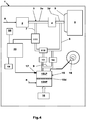
- a method 200 of controlling an aspirator valve starts at box 210 which represents a key-on event.
- the electrical circuits of the motor vehicle and the starting of an engine of the motor vehicle were affected via a key operated switch often referred to as an 'ignition switch'.
- a further movement of the switch is used to engage the starter of the engine and so there is normally a short delay between when the electrical circuits are enabled and when the engine of the motor vehicle is actually running.
- HMI machine-human interface
- the method moves to box 220.
- the engine of the motor vehicle will not start immediately following the key-on event there being a short delay between key-on and engine start and it is advantageous if the method 200 in accordance with this invention is executed in this short period before actual engine start.
- box 220 it is checked whether conditions indicative of a need to clear ice (de-ice the aspirator valve) from the aspirator valve are present. If such conditions are not present the method advances directly to box 250 and the aspirator valve is controlled in a normal mode of operation to provide the required vacuum for a brake booster. From box 250 the method advances to box 260 to check whether a key-off event has occurred and if it has the method ends at box 290 otherwise it returns to box 250. It will be appreciated that whenever a key-off event occurs the method will end.
- box 220 If in box 220 the result of the assessment is that it is likely that ice has formed in the aspirator valve that will prevent it operating or prevent it operating normally then the method advances to box 230.
- the aspirator valve is fully opened and closed rapidly a number of times to break down the ice that may have formed.
- the number of cycles of this de-icing operation can be a fixed amount or can be varied based upon the severity of the operating conditions in which the aspirator valve is operating. For example, if a measured temperature of the aspirator valve is close to zero, then only a few cycles of ice clearing opening and closing is used but, if the measured temperature of the aspirator valve is circa minus 20°C, then a larger number of ice clearing cycles is used.
- the method advances in this case to box 240 where it is checked whether the aspirator valve is operating correctly.
- the correct operation of the aspirator valve can be assess in several ways such as, for example, by using a position sensor to physically measure the position of the moveable valve member of the aspirator valve as it is cycled or by comparing the force required to open the aspirator valve to a predefined value. For example, in the case of an electric solenoid operated aspirator valve, this assessment could be a comparison of a measurement of current draw versus expected current draw to open the aspirator valve.
- the step referred to in box 240 is not used and the method advances directly from box 230 to box 250 but in either case after de-icing has taken place the method arrives at box 250 where the aspirator valve is controlled in a normal mode of operation to provide the required vacuum for a brake booster. Prior to reaching box 250 the engine will have started and so the engine will be running when box 250 is entered.
- box 250 From box 250 the method advances to box 260 to check whether a key-off event has occurred and, if it has, the method ends at box 290 otherwise it returns to box 250.
- the aspirator valve when ice is potentially present in the aspirator valve the aspirator valve is fully opened and closed rapidly to break up any ice that may interfere with normal operation of the aspirator valve. It will be appreciated that the 'de-icing' will not remove all of the ice from the aspirator valve it will merely make sure that any ice remaining will not affect the operation of the aspirator valve. It will be appreciated that after a few minutes of engine running the aspirator valve will be heated by the engine and any remaining ice will melt.
- a motor vehicle 1 having an engine 6 and a vacuum assisted braking system including a combined valve and aspirator assembly 10.
- Ambient air is admitted to an induction system 3 for the engine 6 via an inlet 2 as indicated by the arrow 'A'.
- the inlet 2 may included an air filter to remove particulate matter from the air entering the induction system 3.
- the induction system 3 comprises a first part 3u located upstream from a throttle valve 4 and a second part 3d located downstream from the throttle valve 4.
- a combined valve and aspirator assembly 10 comprises an aspirator valve 11 and an aspirator 12.
- the aspirator 12 has an inlet end 12i connected to the first part 3u of the induction system 3 at a position upstream from the throttle valve 4 via a first conduit 7 and an outlet end 12o connected via second conduit 8 to the second part 3d of the induction system 3 at a position downstream from the throttle valve 4 and upstream from an inlet manifold 5 of the engine 6.
- the aspirator 12 has a vacuum inlet 12s connected via a first one way valve 13 to a low pressure side 15LP of a vacuum brake booster 15.
- the vacuum brake booster 15 also includes a diaphragm 15d separating the low pressure side 15LP from a high pressure side 15HP of the brake booster 15. Air at atmospheric pressure is admitted to the high pressure side 15HP of the brake booster 15 as indicated by the arrow 'a'.
- a mechanical input is provided to the brake booster 15 from a brake pedal 16 when the brake pedal is depressed by a driver of the motor vehicle 1.
- hydraulic fluid at pressure is supplied from a master cylinder (not shown) forming part the brake booster 15 to a number of brake callipers 18 to effect braking of the vehicle 1.
- a bypass conduit 9 bypasses the first one way valve 13 and includes a second one-way valve 14.
- the non-return valves 13, 14 prevent vacuum from being drawn back from the inlet manifold 5 when the pressure in the low pressure side 15LP of the brake booster 15 is below the pressure in the inlet manifold 5. That is to say, flow from the inlet manifold 5 to the low pressure side 15LP is prevented when the vacuum in the low pressure side 15LP is greater than the vacuum in the inlet manifold 5.
- the bypass conduit 9 is connected at one end at a position between the first one way valve 13 and the low pressure side 15LP and is at an opposite end to the second part 3d of the induction system 3 at a position between the throttle valve 4 and the inlet manifold 5.
- Opening and closing of the aspirator valve 11 is controlled by an electronic controller 20 in response to a number of inputs 50.
- the electronic controller 20 can be a single unit such as a powertrain control module or could be two or more interconnected units or modules operable in combination to effect control of the aspirator valve 11.
- the electronic controller 20 receives, in the case of this example, inputs 50 include an input from a pressure sensor 17 used to sense the magnitude of the vacuum subsisting in the low pressure side 15LP of the brake booster 15 and an input from a temperature sensor (not shown) used to evaluate whether the conditions are indicative of those where icing of the aspirator valve 11 is likely to occur.
- inputs 50 include an input from a pressure sensor 17 used to sense the magnitude of the vacuum subsisting in the low pressure side 15LP of the brake booster 15 and an input from a temperature sensor (not shown) used to evaluate whether the conditions are indicative of those where icing of the aspirator valve 11 is likely to occur.
- Opening and closing of the aspirator valve 11 during normal running of the engine 6 is based at least in part on the magnitude of the pressure sensed to be present in the low pressure side 15LP of the brake booster 15 by the pressure sensor 17. It will be appreciated that in other examples the vacuum subsisting in the low pressure side 15LP of the brake booster 15 could be modelled and not directly sensed.
- the electronic controller 20 may directly control the aspirator valve 11 or may provide a signal to a separate unit (not shown) to control the medium used to control the opening and closing of the aspirator valve 11.
- the electronic controller 20 may control a valve used to control the flow of pneumatic pressure or hydraulic pressure to the aspirator valve 11 or supply a control signal to an electrical power supply or electric power amplifier.
- a human machine interface 19 is provided to switch 'on' and switch 'off' the major electric circuits of the motor vehicle 1 and to control starting and stopping of the engine 6.
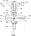
- the combined valve and aspirator assembly 10 comprises the aspirator valve 11 and the aspirator 12 that are coupled together to form the combined valve and aspirator assembly 10.
- the aspirator valve 11 comprises a body 11b in which is mounted an actuator 11a used to move a valve element in the form of a plug valve 11p having an elongate stem 11s supporting a valve head 11v.
- the aspirator valve 11 is a normally closed valve and is opened by the application of pneumatic pressure via an inlet port 11c.
- the invention is not limited to the use of a normally closed aspirator valve or to the type of actuator used for the aspirator valve 11.
- the actuator could be an electrical actuator such as a solenoid valve or a hydraulic actuator.
- the aspirator 12 has a body 12b defining a venturi 12v through which in use air flows in the direction indicated by the arrow 'f'.
- the venturi 12v extends along a longitudinal axis X-X that is shown horizontally disposed in Fig.3 but need not be so disposed.
- An aperture 12a in the aspirator body 12b provides a connection between the venturi 12v and a vacuum inlet 12s.
- the aspirator 12 is conventional in construction and operation.
- the flow of air through the venturi 12v causes the pressure in the region of smallest diameter to drop thereby drawing air out from the low pressure side 15LP of the brake booster 15 via the first one way valve 13 and into the aspirator 12 through the vacuum inlet 12s, as indicated by the arrow 's'.
- the air is then drawn via the aperture 12a into the venturi 12v.
- the electronic controller 20 controls the aspirator valve 11 so as to move the plug valve 11p between a position in which it covers the aperture 12a in the body 12b of the aspirator 12, as shown in figure 2 that is referred to as an aspirator valve 'closed' position to a position in which the plug valve 11p does not obstruct the flow of air through the aperture 12a into the venturi 12v referred to as an aspirator valve 'open' position.
- An annular valve seat surrounds the entrance to the aperture 12a for co-operation with the valve head 11v of the plug valve 11p.
- a compressible seal such as an "0" ring or lip seal to improve sealing between the valve head 11v and the valve seat.
- the plug valve 11p of aspirator valve 11 is moved to the open position when the magnitude of the vacuum in the inlet manifold 5 is less than that required for the low pressure side 15LP of the brake booster 15 and is moved to the closed position when the magnitude of the vacuum in the inlet manifold 5 is sufficient for the low pressure side 15LP of the brake booster 15.
- the electronic controller 20 is programmed in response to an input indicative of the likelihood of icing to rapidly fully open and close the aspirator valve 11 a number of times referred to as 'de-icing cycles' when a key-on event occurs.
- the input to the electronic controller 20 indicative of potential icing can be one of a number of temperature sensor inputs such as for example:-
- the electronic controller 20 can decide whether the aspirator valve 11 needs to be controlled to de-ice it.
- valve head 11v can have a projection that engages with the aperture 12a with clearance when the aspirator valve 11 is closed. In such a case the projection on the valve head 11v will act as an ice pick clearing away any ice within the aperture 12a when ice clearing takes place.
- the number of cycles of opening and closing of the aspirator valve 11 is dependent upon the temperature the vehicle 1 has been idle in so that at very low ambient temperatures well below zero Celsius more open and close cycles are used than in ambient temperature close to zero Celsius.
- the electronic controller 20 in such a case is arranged to vary the number of open and close cycles used to de-ice the aspirator valve based upon an assessment of the severity of potential ice build up.
- the decision as to whether de-icing is required may also be dependent upon the time the vehicle has been idle or a combination of idle time and ambient temperature. This is because if the vehicle is idle in an ambient temperature only slightly below zero Celsius for a short period of time ice will normally not have had time to form due to residual heat from the last engine run cycle. In such a case, the electronic controller 20 assesses the severity of potential ice build up based upon the measurement of the length of time that the engine has remained shutdown and the measurement of the ambient temperature during the shutdown period.
- the aspirator valve 11 is cleared of any ice build up. This is important because it is often the case that following an engine start there is a need for replenishing of the vacuum in the low pressure side 15LP of the brake booster 15 but the magnitude of vacuum available directly from the engine 6 is insufficient to achieve this and so effective operation of the aspirator 12 is required at this point in time.
- a motor vehicle 1 that is in most respects the same as that previously described with respect to Fig.3 and so will not be described again in detail.
- the aspirator valve 111 is separate from the aspirator 112 and is positioned upstream from the aspirator 112 so as to control the flow of air from the first part 3u of the induction system 3 via the first conduit 7 to an inlet end of the aspirator 112 rather than the flow of air from the a low pressure side 15LP of the vacuum brake booster 15.
- Figs.5 and 6 show in greater detail the aspirator valve 111 in respective closed and open states.
- the aspirator valve 111 comprises a body 111b in which is mounted an electric solenoid actuator 111a used to move a valve element in the form of a plug valve 111p.
- the plug valve 111p has an elongate stem 111s engaged with the actuator 111a and a valve head 111v supported by the elongate stem 111s.
- a helical spring 111c overlying the elongate stem 111s is used to bias the plug valve 111p into a closed position as shown in Fig.5 .
- An annular ring 111r is used to support the actuator 111a within a cavity 111f defined by the body 111b.
- the annular ring 111r has a number of circumferentially spaced apertures or holes 111h formed therein to allow air to flow from an inlet 111i of the aspirator valve 111 to an outlet 111e of the aspirator valve 111 when the aspirator valve 111 is in an open state as shown in Fig.6 .
- the aspirator valve 111 is a normally closed valve and is opened by the application of electrical power to the electric solenoid actuator 111.
- the invention is not limited to the use of a normally closed aspirator valve or to the type of actuator used for the aspirator valve 111.
- the actuator could be a pneumatic actuator or a hydraulic actuator.
- the aspirator valve 111 will be opened when there is insufficient vacuum being generated in the intake manifold 5 to produce the required vacuum in the low pressure side 15LP of the vacuum brake booster 15 and that the bypass conduit 9 that bypasses the first one way valve 13 and includes the second one-way valve 14 is used to produce the required vacuum in the low pressure side 15LP of a vacuum brake booster 15 when the aspirator valve 111 is closed and there is sufficient vacuum being generated in the intake manifold 5.
- the valve head 111v of the aspirator valve 111 is moveable between open and closed positions by the solenoid actuator 111a in response to a control signal or signals from the electronic controller 20.
- the valve head 111v of the aspirator valve 111 is spaced a distance "d" from an annular valve seat 111x formed in the valve body 111b for co-operation with the valve head 111v.
- air can flow freely from the inlet 111i of the aspirator valve 111 to the outlet 111e of the aspirator valve 111 and from there to the aspirator 112.
- valve head 111v When the aspirator valve 111 is in the closed state the valve head 111v abuts against the valve seat 111x and, although not shown, a compressible seal located between the valve seat 111x and the valve head 111v will be compressed thereby preventing air from flowing through the aspirator valve 111.
- the aspirator 112 shown in Fig.7 has a body 112b defining a venturi 112v having an inlet end 112i arranged to receive a supply of air from the aspirator valve and an outlet end 112o connected by the second conduit 8 to the second part 3d of the induction system 3 at a position downstream from the throttle valve 4 and upstream from an inlet manifold 5 of the engine 6..
- air flows in the direction indicated by the arrow "F" from the inlet 112i to the outlet 112o of the venturi 112v.
- An aperture 112a in the aspirator body 112b at the smallest diameter provides a connection between the venturi 112v and a vacuum inlet 112s connected to the low pressure side 15LP of a vacuum brake booster 15.
- the aspirator 112 is conventional in construction and operation.
- the flow of air through the venturi 112v causes the pressure in the region of smallest diameter to drop thereby drawing air out from the low pressure side 15LP of the brake booster 15 via the first one way valve 13 and into the aspirator 112 through the vacuum inlet 112s.
- the air is then drawn via the aperture 112a into the venturi 112v.
- the electronic controller 20 controls the aspirator valve 111 so as to move the plug valve 111p between the 'closed' position to a position in which the plug valve 111p does not obstruct the flow of air through the body 111b referred to as an aspirator valve 'open' position.
- the aspirator valve 111 during normal operation is moved to the open position when the magnitude of the vacuum in the inlet manifold 5 is less than that required for the low pressure side 15LP of the brake booster 15 and is moved to the closed position when the magnitude of the vacuum in the inlet manifold 5 is sufficient for the low pressure side 15LP of the brake booster 15. Therefore during normal running of the engine 6 the operation of the aspirator valve 111 is arranged to follow conventional practice.
- the electronic controller 20 is programmed in response to an input indicative of potential icing to rapidly fully open and close the aspirator valve 111 as soon as the engine is restarted.
- the input indicative of potential icing is as before an input from one or more temperature sensors forming one of the inputs 50 to the electronic controller 20.
- This rapid opening and closing of the aspirator valve 111 will break up any ice that has formed around the plug valve 111p between the valve head 111v and the body 111b.
- valve head 111v can have a projection that engages with the inlet 111i of the body 111b with clearance when the aspirator valve 111 is in the closed state.
- the projection will act as an ice pick breaking up ice in the inlet 111i close to the valve seat 111x when de-icing takes place.
- the number of cycles of opening and closing of the aspirator valve 111 can be based upon the temperature the vehicle 1 has been idle in so that at very low ambient temperatures well below zero Celsius more open and close cycles are used than in ambient temperature close to zero Celsius. In other embodiments a fixed number of cycles are used.
- the electronic controller 20 in such a case is arranged to vary the number of open and close cycles used to de-ice the aspirator valve based upon an assessment of the severity of potential ice build up.
- the decision as to whether de-icing is required may also be dependent upon the time the vehicle has been idle or a combination of idle time and ambient temperature. This is because if the vehicle is idle in an ambient temperature only slightly below zero Celsius for a short period of time ice will normally not have had time to form due to residual heat from the last engine run cycle. In such a case, the electronic controller 20 assesses the severity of potential ice build up based upon the measurement of the length of time that the engine has remained shutdown and the measurement of the ambient temperature during the shutdown period.
- de-ice means to clear ice that has built up in the aspirator valve by a percussive process and not melt ice in the aspirator valve.
Landscapes
- Engineering & Computer Science (AREA)
- Mechanical Engineering (AREA)
- Transportation (AREA)
- Physics & Mathematics (AREA)
- Fluid Mechanics (AREA)
- General Engineering & Computer Science (AREA)
- Valves And Accessory Devices For Braking Systems (AREA)
- Braking Arrangements (AREA)
Claims (14)
- Verfahren zum Steuern eines Ansaugventils (11, 111) eines vakuumunterstützten Bremssystems eines Kraftfahrzeugs (1) mit einem Motor (6), dadurch gekennzeichnet, dass, wenn nach einer Zeitperiode, in der der Motor (6) des Kraftfahrzeugs (1) abgestellt war, ein Schlüssel-ein-Ereignis eintritt, das Verfahren das Prüfen, ob eine oder mehrere Fahrzeugbedingungen einen Bedarf zum Enteisen des Ansaugventils (11, 111) anzeigen, und wenn eine oder mehrere Fahrzeugbedingungen anzeigen, dass ein Bedarf zum Enteisen des Ansaugventils (11, 111) besteht, das schnelle vollständige mehrmalige Öffnen und Schließen des Ansaugventils (11, 111), um das Ansaugventil (11, 111) zu enteisen, umfasst.
- Verfahren nach Anspruch 1, wobei die Fahrzeugbedingungen, die einen Bedarf zum Enteisen des Ansaugventils (11, 111) anzeigen, eine aktuelle Temperatur, die unter einem vordefinierten Temperaturgrenzwert liegt, umfassen.
- Verfahren nach Anspruch 2, wobei der Bedarf durch Vergleichen der aktuellen Temperatur mit dem vordefinierten Temperaturgrenzwert festgelegt wird.
- Verfahren nach Anspruch 2 oder Anspruch 3, wobei die aktuelle Temperatur eines von einer Umgebungstemperatur, einer Motorkühlmitteltemperatur, einer Motoröltemperatur, einer Motorlufteinlassverteilertemperatur und einer Ansaugventiltemperatur ist.
- Verfahren nach einem der Ansprüche 1 bis 4, wobei das Verfahren ferner das Variieren der Anzahl von Zyklen, bei denen das Ansaugventil (11, 111) geöffnet und geschlossen wird, auf Basis einer Beurteilung des Ausmaßes einer potenziellen Eisansammlung umfasst.
- Verfahren nach Anspruch 5, wobei das Ausmaß einer potenziellen Eisansammlung auf Basis der Länge der Zeit, die der Motor (6) abgestellt war, und der Umgebungstemperatur während der Abstellperiode beurteilt wird.
- Verfahren nach einem der Ansprüche 1 bis 6, wobei mindestens ein Eisbruchzyklus abgeschlossen wird, bevor der Motor (6) nach einem Schlüssel-ein-Ereignis läuft.
- Kraftfahrzeug (1) mit einem Motor (6), einer Mensch-Maschine-Schnittstelle (19) zum Ein- und Ausschalten der elektrischen Schaltungen und des Motors (6) sowie einem vakuumunterstützten Bremssystem, das ein Ansaugventil (11, 111), eine Ansaugvorrichtung (12, 112) und eine elektronische Steuerung (20) zum Steuern des Öffnens und Schließens des Ansaugventils (11, 111) in Reaktion auf eine oder mehrere Eingaben (50) beinhaltet, dadurch gekennzeichnet, dass, wenn nach einer Zeitperiode, während der der Motor (6) des Kraftfahrzeugs (1) abgestellt war, ein Schlüssel-ein-Ereignis eintritt, die elektronische Steuerung (20) angeordnet ist zu prüfen, ob mindestens eine Eingabe (50) einen Bedarf zum Enteisen des Ansaugventils (11, 111) anzeigt, und wenn mindestens eine Eingabe einen Bedarf zum Enteisen des Ansaugventils (11, 111) anzeigt, die elektronische Steuerung (20) angeordnet ist, den Aktuator (11a, 111a) des Ansaugventils (11, 111) zu betätigen, um eine Anzahl von schnellen und vollständigen Öffnungs- und Schließzyklen des Ansaugventils (11, 111) zu produzieren.
- Fahrzeug nach Anspruch 8, wobei mindestens eine Eingabe, die einen Bedarf zum Entfernen von Eis anzeigt, eine aktuelle erfasste Temperatur umfasst, die unter einem vordefinierten Temperaturgrenzwert liegt.
- Fahrzeug nach Anspruch 9, wobei der Bedarf durch die elektronische Steuerung (20), die die aktuelle erfasste Temperatur mit dem vordefinierten Temperaturgrenzwert vergleicht, festgelegt wird.
- Fahrzeug nach Anspruch 9 oder Anspruch 10, wobei die mindestens eine Eingabe eines von einer erfassten aktuellen Umgebungstemperatur, einer erfassten aktuellen Motorkühlmitteltemperatur, einer erfassten aktuellen Motoröltemperatur, einer erfassten aktuellen Temperatur eines Lufteinlassverteilers (5) des Motors (6) und einer erfassten aktuellen Temperatur eines Teils des Ansaugventils (11, 111) ist.
- Fahrzeug nach einem der Ansprüche 8 bis 11, wobei die elektronische Steuerung (20) ferner angeordnet ist, die Anzahl der Öffnungs- und Schließzyklen, die verwendet werden, um das Ansaugventil (11, 111) zu enteisen, auf Basis einer Beurteilung des Ausmaßes einer potenziellen Eisansammlung zu variieren.
- Fahrzeug nach Anspruch 12, wobei das Ausmaß einer potenziellen Eisansammlung auf Basis einer Messung der Länge der Zeit, die der Motor (6) abgestellt war, und einer Messung der Umgebungstemperatur während der Abstellperiode beurteilt wird.
- Fahrzeug nach einem der Ansprüche 8 bis 13, wobei die elektronische Steuerung (20) angeordnet ist, nach einem Schlüssel-ein-Ereignis mindestens einen Öffnungs- und Schließzyklus des Ansaugventils (11, 111) auszuführen, bevor der Motor (6) läuft.
Applications Claiming Priority (1)
| Application Number | Priority Date | Filing Date | Title |
|---|---|---|---|
| GB1614051.9A GB2552976B (en) | 2016-08-17 | 2016-08-17 | A method of controlling an aspirator valve |
Publications (2)
| Publication Number | Publication Date |
|---|---|
| EP3284644A1 EP3284644A1 (de) | 2018-02-21 |
| EP3284644B1 true EP3284644B1 (de) | 2019-09-04 |
Family
ID=56985812
Family Applications (1)
| Application Number | Title | Priority Date | Filing Date |
|---|---|---|---|
| EP17275103.4A Active EP3284644B1 (de) | 2016-08-17 | 2017-07-11 | Verfahren zur steuerung eines ansaugventils |
Country Status (6)
| Country | Link |
|---|---|
| US (1) | US10053077B2 (de) |
| EP (1) | EP3284644B1 (de) |
| CN (1) | CN107757594A (de) |
| GB (1) | GB2552976B (de) |
| MX (1) | MX2017010559A (de) |
| RU (1) | RU2017128948A (de) |
Families Citing this family (4)
| Publication number | Priority date | Publication date | Assignee | Title |
|---|---|---|---|---|
| CN109572649B (zh) * | 2018-12-30 | 2023-10-24 | 吉林东光奥威汽车制动系统有限公司 | 一种适应高原和平原地区的电动真空泵控制装置 |
| EP3757400B1 (de) * | 2019-06-28 | 2024-11-06 | Goodrich Corporation | Druckregler für aufblasanlagen |
| CN114575963B (zh) * | 2021-02-19 | 2023-05-02 | 长城汽车股份有限公司 | 曲通管结冰清除装置及清除系统和清除方法 |
| CN114852026B (zh) * | 2022-05-23 | 2023-08-11 | 安徽江淮汽车集团股份有限公司 | 一种汽油车制动真空助力系统及控制方法 |
Family Cites Families (6)
| Publication number | Priority date | Publication date | Assignee | Title |
|---|---|---|---|---|
| KR100482139B1 (ko) * | 2002-11-23 | 2005-04-14 | 현대자동차주식회사 | 결빙 방지 체크밸브 |
| JP2008267270A (ja) * | 2007-04-20 | 2008-11-06 | Toyota Motor Corp | 負圧発生装置の制御装置 |
| JP4345841B2 (ja) * | 2007-04-25 | 2009-10-14 | トヨタ自動車株式会社 | 負圧発生装置の制御装置 |
| US9551435B2 (en) * | 2014-06-05 | 2017-01-24 | Dunan Microstaq, Inc. | Method of preventing clogging in a microvalve |
| GB2534564B (en) * | 2015-01-27 | 2017-04-26 | Ford Global Tech Llc | A method for cleaning a valve |
| GB2532092B (en) * | 2015-02-20 | 2017-01-25 | Ford Global Tech Llc | A method for preventing malfunctioning of a combined valve and aspirator assembly |
-
2016
- 2016-08-17 GB GB1614051.9A patent/GB2552976B/en not_active Expired - Fee Related
-
2017
- 2017-07-11 EP EP17275103.4A patent/EP3284644B1/de active Active
- 2017-08-14 CN CN201710689947.1A patent/CN107757594A/zh active Pending
- 2017-08-15 RU RU2017128948A patent/RU2017128948A/ru not_active Application Discontinuation
- 2017-08-16 MX MX2017010559A patent/MX2017010559A/es unknown
- 2017-08-16 US US15/678,773 patent/US10053077B2/en not_active Expired - Fee Related
Non-Patent Citations (1)
| Title |
|---|
| None * |
Also Published As
| Publication number | Publication date |
|---|---|
| US20180050677A1 (en) | 2018-02-22 |
| EP3284644A1 (de) | 2018-02-21 |
| MX2017010559A (es) | 2018-09-19 |
| GB201614051D0 (en) | 2016-09-28 |
| CN107757594A (zh) | 2018-03-06 |
| US10053077B2 (en) | 2018-08-21 |
| RU2017128948A (ru) | 2019-02-20 |
| GB2552976B (en) | 2018-09-05 |
| GB2552976A (en) | 2018-02-21 |
Similar Documents
| Publication | Publication Date | Title |
|---|---|---|
| EP3284644B1 (de) | Verfahren zur steuerung eines ansaugventils | |
| CN111936732B (zh) | 用于涡轮增压器系统的车载诊断的方法和涡轮增压器系统 | |
| CN105835865B (zh) | 用于检测车辆的制动助力器系统内的故障的系统和方法 | |
| JP5707967B2 (ja) | 内燃機関の過給圧診断装置 | |
| RU2513991C1 (ru) | Устройство для диагностики неисправностей расходомера воздуха | |
| US20070234716A1 (en) | Vehicular ejector system and controller and control method for vehicular ejector system | |
| CN106062328B (zh) | 用于从曲轴箱中移除所泄漏的曲轴箱流体的方法和曲轴箱通风系统 | |
| KR20010076158A (ko) | 차량에 진공을 제공하기 위한 장치 및 방법 | |
| US20100222991A1 (en) | Method for operating an internal combustion engine | |
| US10119555B2 (en) | Pneumatic actuator system and method for controlling such as system | |
| CN114207259A (zh) | 内燃机的漏气处理装置的泄漏诊断方法以及泄漏诊断装置 | |
| RU2698615C2 (ru) | Способ предотвращения неисправной работы комбинированного узла клапана и аспиратора моторного транспортного средства и моторное транспортное средство | |
| US9956946B2 (en) | Method for cleaning a valve | |
| KR101163283B1 (ko) | 음압 생성 장치용 제어 장치 및 제어 방법 | |
| US9663090B2 (en) | Brake booster assistance | |
| EP2541016A1 (de) | Steuervorrichtung für einen verbrennungsmotor | |
| CN114207401A (zh) | 内燃机的漏气处理装置的泄漏诊断方法以及泄漏诊断装置 | |
| KR20080088626A (ko) | 하이브리드 구동기용 모니터링 방법 | |
| JP2001152882A (ja) | 内燃機関の電磁駆動バルブの異常診断装置 | |
| JP2010242530A (ja) | 油圧制御装置 | |
| JP3942556B2 (ja) | 過給機付き内燃機関のウエストゲートバルブ制御装置 | |
| JP3552473B2 (ja) | 車両用ブレーキ装置 | |
| EP2742217B1 (de) | Steuervorrichtung für einen verbrennungsmotor und steuerverfahren für einen verbrennungsmotor | |
| JP4390790B2 (ja) | 過給機付き内燃機関のウエストゲートバルブ制御装置 | |
| CN111102103A (zh) | 箱排气系统和用于诊断箱排气系统的方法 |
Legal Events
| Date | Code | Title | Description |
|---|---|---|---|
| PUAI | Public reference made under article 153(3) epc to a published international application that has entered the european phase |
Free format text: ORIGINAL CODE: 0009012 |
|
| STAA | Information on the status of an ep patent application or granted ep patent |
Free format text: STATUS: THE APPLICATION HAS BEEN PUBLISHED |
|
| AK | Designated contracting states |
Kind code of ref document: A1 Designated state(s): AL AT BE BG CH CY CZ DE DK EE ES FI FR GB GR HR HU IE IS IT LI LT LU LV MC MK MT NL NO PL PT RO RS SE SI SK SM TR |
|
| AX | Request for extension of the european patent |
Extension state: BA ME |
|
| STAA | Information on the status of an ep patent application or granted ep patent |
Free format text: STATUS: REQUEST FOR EXAMINATION WAS MADE |
|
| 17P | Request for examination filed |
Effective date: 20180821 |
|
| RBV | Designated contracting states (corrected) |
Designated state(s): AL AT BE BG CH CY CZ DE DK EE ES FI FR GB GR HR HU IE IS IT LI LT LU LV MC MK MT NL NO PL PT RO RS SE SI SK SM TR |
|
| GRAP | Despatch of communication of intention to grant a patent |
Free format text: ORIGINAL CODE: EPIDOSNIGR1 |
|
| STAA | Information on the status of an ep patent application or granted ep patent |
Free format text: STATUS: GRANT OF PATENT IS INTENDED |
|
| INTG | Intention to grant announced |
Effective date: 20190227 |
|
| GRAS | Grant fee paid |
Free format text: ORIGINAL CODE: EPIDOSNIGR3 |
|
| GRAA | (expected) grant |
Free format text: ORIGINAL CODE: 0009210 |
|
| STAA | Information on the status of an ep patent application or granted ep patent |
Free format text: STATUS: THE PATENT HAS BEEN GRANTED |
|
| AK | Designated contracting states |
Kind code of ref document: B1 Designated state(s): AL AT BE BG CH CY CZ DE DK EE ES FI FR GB GR HR HU IE IS IT LI LT LU LV MC MK MT NL NO PL PT RO RS SE SI SK SM TR |
|
| REG | Reference to a national code |
Ref country code: GB Ref legal event code: FG4D |
|
| REG | Reference to a national code |
Ref country code: CH Ref legal event code: EP |
|
| REG | Reference to a national code |
Ref country code: AT Ref legal event code: REF Ref document number: 1174929 Country of ref document: AT Kind code of ref document: T Effective date: 20190915 |
|
| REG | Reference to a national code |
Ref country code: DE Ref legal event code: R096 Ref document number: 602017006766 Country of ref document: DE |
|
| REG | Reference to a national code |
Ref country code: IE Ref legal event code: FG4D |
|
| REG | Reference to a national code |
Ref country code: NL Ref legal event code: MP Effective date: 20190904 |
|
| REG | Reference to a national code |
Ref country code: LT Ref legal event code: MG4D |
|
| PG25 | Lapsed in a contracting state [announced via postgrant information from national office to epo] |
Ref country code: BG Free format text: LAPSE BECAUSE OF FAILURE TO SUBMIT A TRANSLATION OF THE DESCRIPTION OR TO PAY THE FEE WITHIN THE PRESCRIBED TIME-LIMIT Effective date: 20191204 Ref country code: NO Free format text: LAPSE BECAUSE OF FAILURE TO SUBMIT A TRANSLATION OF THE DESCRIPTION OR TO PAY THE FEE WITHIN THE PRESCRIBED TIME-LIMIT Effective date: 20191204 Ref country code: SE Free format text: LAPSE BECAUSE OF FAILURE TO SUBMIT A TRANSLATION OF THE DESCRIPTION OR TO PAY THE FEE WITHIN THE PRESCRIBED TIME-LIMIT Effective date: 20190904 Ref country code: FI Free format text: LAPSE BECAUSE OF FAILURE TO SUBMIT A TRANSLATION OF THE DESCRIPTION OR TO PAY THE FEE WITHIN THE PRESCRIBED TIME-LIMIT Effective date: 20190904 Ref country code: LT Free format text: LAPSE BECAUSE OF FAILURE TO SUBMIT A TRANSLATION OF THE DESCRIPTION OR TO PAY THE FEE WITHIN THE PRESCRIBED TIME-LIMIT Effective date: 20190904 Ref country code: HR Free format text: LAPSE BECAUSE OF FAILURE TO SUBMIT A TRANSLATION OF THE DESCRIPTION OR TO PAY THE FEE WITHIN THE PRESCRIBED TIME-LIMIT Effective date: 20190904 |
|
| PG25 | Lapsed in a contracting state [announced via postgrant information from national office to epo] |
Ref country code: GR Free format text: LAPSE BECAUSE OF FAILURE TO SUBMIT A TRANSLATION OF THE DESCRIPTION OR TO PAY THE FEE WITHIN THE PRESCRIBED TIME-LIMIT Effective date: 20191205 Ref country code: ES Free format text: LAPSE BECAUSE OF FAILURE TO SUBMIT A TRANSLATION OF THE DESCRIPTION OR TO PAY THE FEE WITHIN THE PRESCRIBED TIME-LIMIT Effective date: 20190904 Ref country code: LV Free format text: LAPSE BECAUSE OF FAILURE TO SUBMIT A TRANSLATION OF THE DESCRIPTION OR TO PAY THE FEE WITHIN THE PRESCRIBED TIME-LIMIT Effective date: 20190904 Ref country code: RS Free format text: LAPSE BECAUSE OF FAILURE TO SUBMIT A TRANSLATION OF THE DESCRIPTION OR TO PAY THE FEE WITHIN THE PRESCRIBED TIME-LIMIT Effective date: 20190904 Ref country code: AL Free format text: LAPSE BECAUSE OF FAILURE TO SUBMIT A TRANSLATION OF THE DESCRIPTION OR TO PAY THE FEE WITHIN THE PRESCRIBED TIME-LIMIT Effective date: 20190904 |
|
| REG | Reference to a national code |
Ref country code: AT Ref legal event code: MK05 Ref document number: 1174929 Country of ref document: AT Kind code of ref document: T Effective date: 20190904 |
|
| PG25 | Lapsed in a contracting state [announced via postgrant information from national office to epo] |
Ref country code: PT Free format text: LAPSE BECAUSE OF FAILURE TO SUBMIT A TRANSLATION OF THE DESCRIPTION OR TO PAY THE FEE WITHIN THE PRESCRIBED TIME-LIMIT Effective date: 20200106 Ref country code: PL Free format text: LAPSE BECAUSE OF FAILURE TO SUBMIT A TRANSLATION OF THE DESCRIPTION OR TO PAY THE FEE WITHIN THE PRESCRIBED TIME-LIMIT Effective date: 20190904 Ref country code: NL Free format text: LAPSE BECAUSE OF FAILURE TO SUBMIT A TRANSLATION OF THE DESCRIPTION OR TO PAY THE FEE WITHIN THE PRESCRIBED TIME-LIMIT Effective date: 20190904 Ref country code: AT Free format text: LAPSE BECAUSE OF FAILURE TO SUBMIT A TRANSLATION OF THE DESCRIPTION OR TO PAY THE FEE WITHIN THE PRESCRIBED TIME-LIMIT Effective date: 20190904 Ref country code: RO Free format text: LAPSE BECAUSE OF FAILURE TO SUBMIT A TRANSLATION OF THE DESCRIPTION OR TO PAY THE FEE WITHIN THE PRESCRIBED TIME-LIMIT Effective date: 20190904 Ref country code: IT Free format text: LAPSE BECAUSE OF FAILURE TO SUBMIT A TRANSLATION OF THE DESCRIPTION OR TO PAY THE FEE WITHIN THE PRESCRIBED TIME-LIMIT Effective date: 20190904 Ref country code: EE Free format text: LAPSE BECAUSE OF FAILURE TO SUBMIT A TRANSLATION OF THE DESCRIPTION OR TO PAY THE FEE WITHIN THE PRESCRIBED TIME-LIMIT Effective date: 20190904 |
|
| PG25 | Lapsed in a contracting state [announced via postgrant information from national office to epo] |
Ref country code: IS Free format text: LAPSE BECAUSE OF FAILURE TO SUBMIT A TRANSLATION OF THE DESCRIPTION OR TO PAY THE FEE WITHIN THE PRESCRIBED TIME-LIMIT Effective date: 20200224 Ref country code: CZ Free format text: LAPSE BECAUSE OF FAILURE TO SUBMIT A TRANSLATION OF THE DESCRIPTION OR TO PAY THE FEE WITHIN THE PRESCRIBED TIME-LIMIT Effective date: 20190904 Ref country code: SK Free format text: LAPSE BECAUSE OF FAILURE TO SUBMIT A TRANSLATION OF THE DESCRIPTION OR TO PAY THE FEE WITHIN THE PRESCRIBED TIME-LIMIT Effective date: 20190904 Ref country code: SM Free format text: LAPSE BECAUSE OF FAILURE TO SUBMIT A TRANSLATION OF THE DESCRIPTION OR TO PAY THE FEE WITHIN THE PRESCRIBED TIME-LIMIT Effective date: 20190904 |
|
| REG | Reference to a national code |
Ref country code: DE Ref legal event code: R097 Ref document number: 602017006766 Country of ref document: DE |
|
| PLBE | No opposition filed within time limit |
Free format text: ORIGINAL CODE: 0009261 |
|
| STAA | Information on the status of an ep patent application or granted ep patent |
Free format text: STATUS: NO OPPOSITION FILED WITHIN TIME LIMIT |
|
| PG2D | Information on lapse in contracting state deleted |
Ref country code: IS |
|
| PG25 | Lapsed in a contracting state [announced via postgrant information from national office to epo] |
Ref country code: DK Free format text: LAPSE BECAUSE OF FAILURE TO SUBMIT A TRANSLATION OF THE DESCRIPTION OR TO PAY THE FEE WITHIN THE PRESCRIBED TIME-LIMIT Effective date: 20190904 Ref country code: IS Free format text: LAPSE BECAUSE OF FAILURE TO SUBMIT A TRANSLATION OF THE DESCRIPTION OR TO PAY THE FEE WITHIN THE PRESCRIBED TIME-LIMIT Effective date: 20200105 |
|
| 26N | No opposition filed |
Effective date: 20200605 |
|
| PG25 | Lapsed in a contracting state [announced via postgrant information from national office to epo] |
Ref country code: SI Free format text: LAPSE BECAUSE OF FAILURE TO SUBMIT A TRANSLATION OF THE DESCRIPTION OR TO PAY THE FEE WITHIN THE PRESCRIBED TIME-LIMIT Effective date: 20190904 |
|
| REG | Reference to a national code |
Ref country code: DE Ref legal event code: R082 Ref document number: 602017006766 Country of ref document: DE Representative=s name: HL KEMPNER PATENTANWALT, RECHTSANWALT, SOLICIT, DE |
|
| PG25 | Lapsed in a contracting state [announced via postgrant information from national office to epo] |
Ref country code: MC Free format text: LAPSE BECAUSE OF FAILURE TO SUBMIT A TRANSLATION OF THE DESCRIPTION OR TO PAY THE FEE WITHIN THE PRESCRIBED TIME-LIMIT Effective date: 20190904 |
|
| REG | Reference to a national code |
Ref country code: CH Ref legal event code: PL |
|
| REG | Reference to a national code |
Ref country code: BE Ref legal event code: MM Effective date: 20200731 |
|
| PG25 | Lapsed in a contracting state [announced via postgrant information from national office to epo] |
Ref country code: FR Free format text: LAPSE BECAUSE OF NON-PAYMENT OF DUE FEES Effective date: 20200731 Ref country code: LI Free format text: LAPSE BECAUSE OF NON-PAYMENT OF DUE FEES Effective date: 20200731 Ref country code: LU Free format text: LAPSE BECAUSE OF NON-PAYMENT OF DUE FEES Effective date: 20200711 Ref country code: CH Free format text: LAPSE BECAUSE OF NON-PAYMENT OF DUE FEES Effective date: 20200731 |
|
| PG25 | Lapsed in a contracting state [announced via postgrant information from national office to epo] |
Ref country code: BE Free format text: LAPSE BECAUSE OF NON-PAYMENT OF DUE FEES Effective date: 20200731 |
|
| PG25 | Lapsed in a contracting state [announced via postgrant information from national office to epo] |
Ref country code: IE Free format text: LAPSE BECAUSE OF NON-PAYMENT OF DUE FEES Effective date: 20200711 |
|
| PGFP | Annual fee paid to national office [announced via postgrant information from national office to epo] |
Ref country code: DE Payment date: 20210616 Year of fee payment: 5 |
|
| GBPC | Gb: european patent ceased through non-payment of renewal fee |
Effective date: 20210711 |
|
| PG25 | Lapsed in a contracting state [announced via postgrant information from national office to epo] |
Ref country code: GB Free format text: LAPSE BECAUSE OF NON-PAYMENT OF DUE FEES Effective date: 20210711 |
|
| PG25 | Lapsed in a contracting state [announced via postgrant information from national office to epo] |
Ref country code: TR Free format text: LAPSE BECAUSE OF FAILURE TO SUBMIT A TRANSLATION OF THE DESCRIPTION OR TO PAY THE FEE WITHIN THE PRESCRIBED TIME-LIMIT Effective date: 20190904 Ref country code: MT Free format text: LAPSE BECAUSE OF FAILURE TO SUBMIT A TRANSLATION OF THE DESCRIPTION OR TO PAY THE FEE WITHIN THE PRESCRIBED TIME-LIMIT Effective date: 20190904 Ref country code: CY Free format text: LAPSE BECAUSE OF FAILURE TO SUBMIT A TRANSLATION OF THE DESCRIPTION OR TO PAY THE FEE WITHIN THE PRESCRIBED TIME-LIMIT Effective date: 20190904 |
|
| PG25 | Lapsed in a contracting state [announced via postgrant information from national office to epo] |
Ref country code: MK Free format text: LAPSE BECAUSE OF FAILURE TO SUBMIT A TRANSLATION OF THE DESCRIPTION OR TO PAY THE FEE WITHIN THE PRESCRIBED TIME-LIMIT Effective date: 20190904 |
|
| REG | Reference to a national code |
Ref country code: DE Ref legal event code: R119 Ref document number: 602017006766 Country of ref document: DE |
|
| PG25 | Lapsed in a contracting state [announced via postgrant information from national office to epo] |
Ref country code: DE Free format text: LAPSE BECAUSE OF NON-PAYMENT OF DUE FEES Effective date: 20230201 |