EP3757400B1 - Druckregler für aufblasanlagen - Google Patents
Druckregler für aufblasanlagen Download PDFInfo
- Publication number
- EP3757400B1 EP3757400B1 EP19461551.4A EP19461551A EP3757400B1 EP 3757400 B1 EP3757400 B1 EP 3757400B1 EP 19461551 A EP19461551 A EP 19461551A EP 3757400 B1 EP3757400 B1 EP 3757400B1
- Authority
- EP
- European Patent Office
- Prior art keywords
- fluid
- convergent
- outlet
- outlet pipe
- divergent nozzle
- Prior art date
- Legal status (The legal status is an assumption and is not a legal conclusion. Google has not performed a legal analysis and makes no representation as to the accuracy of the status listed.)
- Active
Links
Images


Classifications
-
- B—PERFORMING OPERATIONS; TRANSPORTING
- B64—AIRCRAFT; AVIATION; COSMONAUTICS
- B64D—EQUIPMENT FOR FITTING IN OR TO AIRCRAFT; FLIGHT SUITS; PARACHUTES; ARRANGEMENT OR MOUNTING OF POWER PLANTS OR PROPULSION TRANSMISSIONS IN AIRCRAFT
- B64D25/00—Emergency apparatus or devices, not otherwise provided for
- B64D25/08—Ejecting or escaping means
- B64D25/14—Inflatable escape chutes
-
- F—MECHANICAL ENGINEERING; LIGHTING; HEATING; WEAPONS; BLASTING
- F04—POSITIVE - DISPLACEMENT MACHINES FOR LIQUIDS; PUMPS FOR LIQUIDS OR ELASTIC FLUIDS
- F04F—PUMPING OF FLUID BY DIRECT CONTACT OF ANOTHER FLUID OR BY USING INERTIA OF FLUID TO BE PUMPED; SIPHONS
- F04F5/00—Jet pumps, i.e. devices in which flow is induced by pressure drop caused by velocity of another fluid flow
- F04F5/14—Jet pumps, i.e. devices in which flow is induced by pressure drop caused by velocity of another fluid flow the inducing fluid being elastic fluid
- F04F5/16—Jet pumps, i.e. devices in which flow is induced by pressure drop caused by velocity of another fluid flow the inducing fluid being elastic fluid displacing elastic fluids
-
- F—MECHANICAL ENGINEERING; LIGHTING; HEATING; WEAPONS; BLASTING
- F04—POSITIVE - DISPLACEMENT MACHINES FOR LIQUIDS; PUMPS FOR LIQUIDS OR ELASTIC FLUIDS
- F04F—PUMPING OF FLUID BY DIRECT CONTACT OF ANOTHER FLUID OR BY USING INERTIA OF FLUID TO BE PUMPED; SIPHONS
- F04F5/00—Jet pumps, i.e. devices in which flow is induced by pressure drop caused by velocity of another fluid flow
- F04F5/44—Component parts, details, or accessories not provided for in, or of interest apart from, groups F04F5/02 - F04F5/42
- F04F5/46—Arrangements of nozzles
- F04F5/465—Arrangements of nozzles with supersonic flow
-
- B—PERFORMING OPERATIONS; TRANSPORTING
- B05—SPRAYING OR ATOMISING IN GENERAL; APPLYING FLUENT MATERIALS TO SURFACES, IN GENERAL
- B05B—SPRAYING APPARATUS; ATOMISING APPARATUS; NOZZLES
- B05B1/00—Nozzles, spray heads or other outlets, with or without auxiliary devices such as valves, heating means
- B05B1/005—Nozzles or other outlets specially adapted for discharging one or more gases
-
- B—PERFORMING OPERATIONS; TRANSPORTING
- B05—SPRAYING OR ATOMISING IN GENERAL; APPLYING FLUENT MATERIALS TO SURFACES, IN GENERAL
- B05B—SPRAYING APPARATUS; ATOMISING APPARATUS; NOZZLES
- B05B12/00—Arrangements for controlling delivery; Arrangements for controlling the spray area
- B05B12/08—Arrangements for controlling delivery; Arrangements for controlling the spray area responsive to condition of liquid or other fluent material to be discharged, of ambient medium or of target ; responsive to condition of spray devices or of supply means, e.g. pipes, pumps or their drive means
- B05B12/085—Arrangements for controlling delivery; Arrangements for controlling the spray area responsive to condition of liquid or other fluent material to be discharged, of ambient medium or of target ; responsive to condition of spray devices or of supply means, e.g. pipes, pumps or their drive means responsive to flow or pressure of liquid or other fluent material to be discharged
-
- F—MECHANICAL ENGINEERING; LIGHTING; HEATING; WEAPONS; BLASTING
- F15—FLUID-PRESSURE ACTUATORS; HYDRAULICS OR PNEUMATICS IN GENERAL
- F15D—FLUID DYNAMICS, i.e. METHODS OR MEANS FOR INFLUENCING THE FLOW OF GASES OR LIQUIDS
- F15D1/00—Influencing flow of fluids
- F15D1/02—Influencing flow of fluids in pipes or conduits
-
- G—PHYSICS
- G05—CONTROLLING; REGULATING
- G05D—SYSTEMS FOR CONTROLLING OR REGULATING NON-ELECTRIC VARIABLES
- G05D16/00—Control of fluid pressure
- G05D16/20—Control of fluid pressure characterised by the use of electric means
- G05D16/2006—Control of fluid pressure characterised by the use of electric means with direct action of electric energy on controlling means
- G05D16/2066—Control of fluid pressure characterised by the use of electric means with direct action of electric energy on controlling means using controlling means acting on the pressure source
-
- G—PHYSICS
- G05—CONTROLLING; REGULATING
- G05D—SYSTEMS FOR CONTROLLING OR REGULATING NON-ELECTRIC VARIABLES
- G05D16/00—Control of fluid pressure
- G05D16/20—Control of fluid pressure characterised by the use of electric means
- G05D16/2093—Control of fluid pressure characterised by the use of electric means with combination of electric and non-electric auxiliary power
- G05D16/2095—Control of fluid pressure characterised by the use of electric means with combination of electric and non-electric auxiliary power using membranes within the main valve
Definitions
- the present invention relates to a pressure regulator that may be used for example in inflation systems for evacuation slides.
- Evacuation slides for aircraft and other structures are inflated using gas, for example from a high pressure source such as a pressurised gas vessel.
- a high pressure source such as a pressurised gas vessel.
- Such systems are fitted with a pressure regulator to ensure that a sufficient inflation pressure is maintained during inflation, given that the pressure of inflating gas will fall during inflation as the pressurising gas empties from the pressurised vessel.
- Such regulators are typically mechanical valves, for example spool or slide valves comprising a spring loaded control element, the spring force reacting aerodynamic forces during operation to provide the necessary regulation.
- Non mechanical arrangements for increasing the volume of gas that is used to inflate an inflatable structure have been proposed.
- US 2019/192884 A1 describes an augmentation amplifier for aspirating gas flow from a surrounding medium, for example the atmosphere.
- the amplifier connects at an inlet to a pressurized gas source and at an outlet to a gas receiver such as an inflatable boat.
- Ambient gas from the atmosphere supplements a source of compressed gas, for example a self contained underwater breathing apparatus (SCUBA) tank.
- the amplifier includes a Venturi conduit which includes a convergent section, a throat, and a diffusion chamber, and a cavity downstream of the Venturi conduit.
- the conduit receives and flows pressurized gas from the inlet through the throat and into the diffusion chamber.
- the cavity receives gas from the atmosphere.
- the diffusion chamber expands and accelerates the pressurized gas from the throat to entrain the ambient gas via aspiration in the cavity.
- the accelerated and ambient gases combine into an exhaust gas which passes into the inflatable structure.
- CN 104 772 241 A discloses an ejector.
- the invention provides a pressure regulator comprising a primary fluid inlet for connection to a source of high pressure fluid and a fluid outlet for connection to a space to receive the high pressure fluid.
- the regulator further comprises a convergent-divergent nozzle having an upstream convergent section, a throat and a downstream divergent section, the primary fluid inlet being in fluid communication with the convergent section of the nozzle.
- the regulator further comprises an outlet pipe having an upstream end arranged around but radially spaced from the outlet of the divergent section of the nozzle. The outlet pipe is arranged to receive fluid flow from the outlet of the divergent section of the nozzle and conduct the fluid flowing from the nozzle to the fluid outlet.
- the radial spacing between the upstream end of the outlet pipe and the outlet of the divergent section of the nozzle forms a secondary fluid inlet for introduction of a fluid into the outlet pipe from outside the nozzle at a location adjacent the outlet of the divergent section of the nozzle.
- the outlet pipe comprises a radially expanding section at its upstream end adjacent the nozzle, and the radially expanding section expands from smaller to larger dimension in a downstream direction, and a flow recirculation conduit connected at a first end to the secondary fluid inlet and configured to be connected at a second end to the space.
- the outlet pipe may be a diffuser
- the outlet pipe may have a constant diameter section downstream of the radially expanding section.
- connection of the flow recirculation conduit to the secondary fluid inlet may be upstream of the outlet of the nozzle.
- the secondary fluid inlet may be an annular space.
- the nozzle and outlet pipe may have the same cross-sectional shape, for example circular.
- the invention also provides an inflation system comprising a source of high pressure fluid, a body for inflation and a pressure regulator in accordance with the invention, wherein the primary fluid inlet of the pressure regulator is connected to the source of high pressure fluid and the fluid outlet of the pressure regulator is connected to the body and the pressure of the source of the high pressure fluid.
- the configuration of the nozzle is such that when the high pressure fluid is supplied to the nozzle from the source, the nozzle will operate as an underexpanded nozzle, so as to produce supersonic flow in the outlet pipe.
- inflation system in accordance with the invention may further comprise an aspirator fluidly connected to the outlet pipe for inducing a supplementary flow of inflation fluid into the body.
- the source of high pressure fluid is a pressurised vessel, for example a bottle or canister.
- the body is an inflatable evacuation slide, for example for an aircraft.
- the invention also provides a method of regulating the pressure of a fluid supplied to a space from a high pressure fluid source.
- the method comprises supplying fluid from the high pressure fluid source to an inlet of a convergent-divergent nozzle, the pressure of the fluid source and configuration of the nozzle being such that the nozzle operates in an underexpanded condition, thereby producing a supersonic flow at an outlet of the nozzle, supplying the underexpanded flow from the outlet of the nozzle to an outlet pipe having an upstream end arranged around but radially spaced from the outlet of the nozzle, expanding the fluid flow in the outlet pipe, conducting the fluid flow from the nozzle to the fluid outlet along the outlet pipe, a flow recirculation conduit connected at a first end to the secondary fluid inlet and configured to be connected at a second end to the space, and introducing a secondary fluid into the outlet pipe at a location adjacent the outlet of the nozzle.
- the outlet pipe comprises a radially expanding section at its upstream end adjacent the nozzle,
- the secondary fluid may be supplied from the space.
- 1%-2% of the mass of fluid entering the space is recirculated to the outlet pipe.
- inflation system 2 comprises a body 4 to be inflated, a vessel 6 holding a high pressure fluid, a pressure regulator 8 for regulating the pressure of the fluid flowing from the vessel 6 to the body 4, a conduit 10 connecting the pressure regulator 8 to the body 4 and a fluid recirculation conduit 12 connecting the body 4 to the pressure regulator 8.
- the vessel 6 holding a high pressure fluid may be provided with a release valve for releasing the high pressure fluid from the vessel in response to an actuating signal.
- a release valve for releasing the high pressure fluid from the vessel in response to an actuating signal.
- the inflatable body 4 may be, for example, an inflatable evacuation slide for an aircraft, an inflatable vessel or some other inflatable device.
- the conduit 10 may be provided with an aspirator 14 (illustrated schematically) for inducing an additional flow of air into the conduit 10 to assist in inflating the body 4.
- aspirators 14 are well known in the art and need not, therefore, be described in further detail here.
- the inflation pressure should be maintained at a sufficiently high level for as long as possible to ensure inflation of the body 4. For example, in the case of an evacuation slide the slide should be fully inflated in a period of 4 to 6 seconds.
- a pressure regulator 8 in accordance with the invention is illustrated in greater detail in Figures 2 to 4 .
- the pressure regulator 8 comprises a primary fluid inlet 20 for connection to the vessel 6.
- a convergent-divergent nozzle 22 is fluidly connected to the primary fluid inlet 20 for receiving pressurised fluid from the vessel 6.
- the nozzle 22 comprises an upstream convergent section 24, a throat 26 and a downstream divergent section 28 (see Figure 4 ).
- the pressure regulator 8 further comprises an outlet pipe 30.
- the outlet pipe 30 has an upstream end 32 arranged around but radially spaced from the outlet 34 of the divergent section 28 of the nozzle 22.
- the outlet pipe 30 is therefore arranged to receive fluid flow from the outlet 34 of the divergent section 28 of the nozzle 22 and conduct the fluid flowing from the nozzle 22 to a fluid outlet 36.
- the fluid outlet 36 may connect directly with the inflatable body 4 or, as shown to the conduit 10 which connects to the inflatable body 4.
- a radial spacing 38 exists between the upstream end 32 of the outlet pipe 30 and the outlet 32 of the divergent section 28 of the nozzle 22.
- this annular space 40 acts as a secondary fluid inlet 42 for introduction of a further fluid into the outlet pipe 30 from outside the nozzle 22 at a location adjacent the outlet 32 of the divergent section 28 of the nozzle 22 in order to influence the flow in the outlet pipe 30 downstream of the nozzle 22 and thereby influence the pressure of the fluid at the regulator fluid outlet 34.
- the outlet 34 is formed with a sharp edge, as shown
- the annular space 40 may, as illustrated schematically in Figure 3 be open to ambient, for example having an open end 50. In other embodiments, however, the open end 50 may be closed, for example by a plate 52 illustrated schematically in Figure 2 .
- the outlet pipe 30 has an upstream radially expanding section 56 at its upstream end adjacent the nozzle 22 and a constant diameter section 58 downstream of the radially expanding section 56.
- the outlet pipe 30 therefore acts as a diffuser.
- the shape of the outlet pipe 30 should be consistent with that of the nozzle 22.
- the outlet pipe 30 is also circular in cross section. It should also be designed so that the radially expanding section smoothly increases in diameter to the constant diameter section so as to avoid sharp or rapid changes in flow which might lead, for example, to flow separation which is undesirable.
- the radius of the outlet pipe 30 may also be important as influences the maximum value of Mach number in the outlet flow.
- the flow of fluid through a converging/diverging nozzle is well known.
- the flow regime is determined by the shape and dimensions of the nozzle and also the pressure ratio which exists across the nozzle. As the pressure ratio across the nozzle increases, the velocity of the fluid flow through the divergent section of the nozzle may increase to supersonic. At relatively high pressure ratios across the nozzle, the flow emanating from the outlet of the divergent section of the nozzle may be "underexpanded".
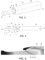
- FIG. 5 illustrates a typical flow velocity distribution in a flow regulator 2 in accordance with the invention.
- expansion waves 44 emanate from the outlet 34 of the divergent section 28 of the nozzle 22.
- Shocks 46 form in the flow further along the outlet pipe 30, further away from the outlet 34 of the convergent section 28 of the nozzle 22.
- the effect of the shocks 46 is to reduce the total pressure of the flow through the regulator to a pressure which is compatible with the pressure required for inflation of the inflatable body 4.
- the particular arrangement of the shocks 46 will depend upon the shape and configuration of the nozzle 22 and also the shape and configuration of the outlet pipe 30.
- the nozzle 22 has an inlet radius L i of 5mm an outlet radius R 0n also 5mm and a throat radius R t of 3.42mm, an overall length L N of 33 mm and an inlet to throat distance L t of 13.4 mm.
- the outlet pipe has an inlet radius R 2i of 8.92mm and a constant section radius R 0 of 10 mm.
- the radial spacing 38 is 1 mm.
- the dimensions of the nozzle 22 and outlet pipe 30 can be chosen to suit the particular pressure and flow rates required.
- the pressure at the fluid inlet will fall. As it does so, so will the pressure of fluid being supplied to the inflatable body 4.
- a fluid recirculation conduit 12 is provided between the inflatable body 4 and the secondary inlet 42.
- the outlet 54 of the fluid recirculation conduit 12 in the secondary inlet 42 is arranged upstream of the downstream end 28 of the nozzle 22 such that supersonic fluid exiting the nozzle 22 cannot enter the conduit outlet 54 as it would have to turn through 180° to do so.
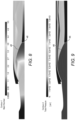
- Figures 6 and 7 show the flow Mach number and total pressure of the fluid in a regulator as illustrated in Figure 2 , with the conduit 12 at the start of inflation.
- the fluid pressure at the nozzle inlet 20 is 2000 psi (13.8MPa) and atmospheric pressure (14.7 psi (101kPa) at the inflatable body 6 and at the secondary inlet 43. In this condition, the average total pressure over the outlet 36 is 685 psi (4.7 MPa).
- Figures 6 and 7 show the flow Mach number and total pressure of the fluid at a later stage in inflation where the inlet pressure has fallen to 1500 psi (10.3MPa) but the pressure within the inflatable body 6 and thus at the secondary inlet 40 has risen to 25 psi (172 kPa) conduit 12. In this condition, the average total pressure over the outlet 36 has fallen to 655 psi (4.5 MPa).
- the percentage may be different, for example between 0.5% and 5%.
- the pressure regulator may be used in other applications where a relatively constant output pressure is required.
- the pressure regulator of the invention is advantageous, inter alia, in that it has no moving parts and as such does not need maintenance to the same degree as a traditional mechanical regulator.
- nozzle 22 and outlet pipe 30 have been illustrated as circular in cross section, in other embodiments they may have a different shape for example elliptical.
- the term "diameter" may be taken as being a significant dimension such as a major axis length. In any event, flow similar to that obtained with a circular cross section can be achieved with consistent cross-sectional areas.
Landscapes
- Engineering & Computer Science (AREA)
- Physics & Mathematics (AREA)
- Fluid Mechanics (AREA)
- Mechanical Engineering (AREA)
- General Engineering & Computer Science (AREA)
- Business, Economics & Management (AREA)
- Emergency Management (AREA)
- Aviation & Aerospace Engineering (AREA)
- Control Of Fluid Pressure (AREA)
- General Physics & Mathematics (AREA)
- Automation & Control Theory (AREA)
- Jet Pumps And Other Pumps (AREA)
Claims (13)
- Druckregler (8), umfassend:einen primären Fluideinlass (20) zur Verbindung mit einer Quelle (6) von Hochdruckfluideinen Fluidauslass (36) zur Verbindung mit einem Raum (4), um das Hochdruckfluid aufzunehmen;eine konvergent-divergente Düse (22), die einen stromaufwärts gelegenen konvergenten Abschnitt (24), eine Verengung (26) und einem stromabwärts gelegenen divergenten Abschnitt (28) aufweist, wobei der primäre Fluideinlass (20) in Fluidverbindung mit dem konvergenten Abschnitt (24) der konvergent-divergenten Düse (22) steht; undein Auslassrohr (30), das ein stromaufwärts gelegenes Ende (32) aufweist, das um den Auslass (34) des divergenten Abschnitts (28) der konvergent-divergenten Düse (22) herum, jedoch radial von diesem beabstandet angeordnet ist, wobei das Auslassrohr (30) so angeordnet ist, dass es einen Fluidstrom aus dem Auslass (34) des divergenten Abschnitts (28) der konvergent-divergenten Düse (22) aufnimmt und das aus der konvergent-divergenten Düse (22) strömende Fluid zu dem Fluidauslass (36) leitet;wobei der radiale Abstand (38) zwischen dem stromaufwärts gelegenen Ende (32) des Auslassrohrs (30) und dem Auslass (34) des divergenten Abschnitts (28) der konvergent-divergenten Düse (22) einen sekundären Fluideinlass (42) zur Einführung eines Fluids in das Auslassrohr (30) von außerhalb der konvergent-divergenten Düse (22) an einer Stelle benachbart zu dem Auslass (34) des divergenten Abschnitts (28) der konvergent-divergenten Düse (22) bildet;wobei das Auslassrohr (30) einen sich radial erweiternden Abschnitt (56) an seinem stromaufwärts gelegenen Ende benachbart zu der konvergenten-divergenten Düse (22) umfasst und sich der sich radial erweiternde Abschnitt (56) in stromabwärtiger Richtung von einer kleineren zu einer größeren Abmessung erweitert; und dadurch gekennzeichnet, dasseine Stromrückführungsleitung (12) an einem ersten Ende mit dem sekundären Fluideinlass (42) verbunden und dazu konfiguriert ist, an einem zweiten Ende mit dem Raum (4) verbunden zu sein.
- Druckregler nach Anspruch 1, wobei das Auslassrohr (30) ein Diffusor ist.
- Druckregler nach Anspruch 1 oder 2, wobei das Auslassrohr (30) stromabwärts des sich radial erweiternden Abschnitts (56) einen Abschnitt (58) mit konstantem Durchmesser aufweist.
- Druckregler nach einem der vorhergehenden Ansprüche, wobei die Verbindung der Stromrückführungsleitung (12) mit dem sekundären Fluideinlass (42) stromaufwärts des Auslasses (34) der konvergent-divergenten Düse (22) liegt.
- Druckregler nach einem der vorhergehenden Ansprüche, wobei der sekundäre Fluideinlass (42) ein ringförmiger Raum ist.
- Druckregler nach einem der vorhergehenden Ansprüche, wobei die konvergent-divergente Düse (22) und das Auslassrohr (30) die gleiche Querschnittsform, beispielsweise kreisförmig, aufweisen.
- Aufblasanlage, umfassend:eine Quelle (6) von Hochdruckfluid;einen Körper (4) zum Aufblasen; undeinen Druckregler (8) nach einem der vorhergehenden Ansprüche;wobei der primäre Fluideinlass (20) des Druckreglers (8) mit der Quelle (6) von Hochdruckfluid verbunden ist und der Fluidauslass (36) des Druckreglers (8) mit dem Körper (4) verbunden ist;wobei der Druck der Quelle (6) von Hochdruckfluid und die Konfiguration der konvergent-divergenten Düse (22) derart sind, dass, wenn das Hochdruckfluid der konvergent-divergenten Düse (22) von der Quelle (6) zugeführt wird, die konvergent-divergente Düse als untererweiterte konvergent-divergente Düse (22) arbeitet, um einen Überschallstrom in dem Auslassrohr (30) zu erzeugen.
- Aufblasanlage nach Anspruch 7, ferner umfassend eine Saugvorrichtung (14), die mit dem Auslassrohr (30) fluidverbunden ist, um einen zusätzlichen Strom von Aufblasfluid in den Körper (4) zu leiten.
- Aufblasanlage nach Anspruch 7 oder 8, wobei die Quelle von Hochdruckfluid ein unter Druck stehender Behälter (6), beispielsweise eine Flasche oder ein Kanister, ist.
- Aufblasanlage nach Anspruch 7, 8 oder 9, wobei der Körper eine aufblasbare Notrutsche, beispielsweise für ein Flugzeug, ist.
- Verfahren zum Regeln des Drucks eines Fluids, das einem Raum (4) von einer Hochdruckfluidquelle (6) zugeführt wird, wobei das Verfahren Folgendes umfasst:Zuführen von Fluid von der Hochdruckfluidquelle (6) zu einem Einlass (20) einer konvergent-divergenten Düse (22), wobei der Druck der Fluidquelle derart ist, dass die konvergent-divergente Düse (22) in einem untererweiterten Zustand arbeitet, wodurch ein Überschallstrom an einem Auslass (34) der konvergent-divergenten Düse (22) erzeugt wird;Zuführen des untererweiterten Stroms aus dem Auslass (34) der konvergent-divergenten Düse (22) zu einem Auslassrohr (30), das ein stromaufwärts gelegenes Ende aufweist, das um den Auslass (34) der konvergent-divergenten Düse (22) herum angeordnet, jedoch radial von diesem beabstandet ist, wobei das Auslassrohr (30) an seinem stromaufwärts gelegenen Ende benachbart zu der konvergent-divergenten Düse (22) einen sich radial erweiternden Abschnitt (56) aufweist und sich der sich radial erweiternde Abschnitt (56) in einer stromabwärts gelegenen Richtung von einer kleineren zu einer größeren Abmessung erweitert, wodurch sich der Fluidstrom in dem Auslassrohr (30) erweitert und der Fluidstrom aus der konvergent-divergenten Düse (22) entlang des Auslassrohrs (30) zu dem Fluidauslass (36) geleitet wird, wobei ein sekundäres Fluid an einer Stelle benachbart zu dem Auslass (34) der konvergent-divergenten Düse (22) in das Auslassrohr (30) eingeführt wird; unddadurch gekennzeichnet, dasseine Stromrückführungsleitung (12) an einem ersten Ende mit dem sekundären Fluideinlass (42) verbunden und dazu konfiguriert ist, an einem zweiten Ende mit dem Raum (4) verbunden zu sein.
- Verfahren nach Anspruch 11, wobei das sekundäre Fluid aus dem Raum (4) zugeführt wird.
- Verfahren nach Anspruch 12, wobei 1 %-2 % der Masse des in den Raum (4) eintretenden Fluids zu dem Auslassrohr (30) zurückgeführt werden.
Priority Applications (2)
| Application Number | Priority Date | Filing Date | Title |
|---|---|---|---|
| EP19461551.4A EP3757400B1 (de) | 2019-06-28 | 2019-06-28 | Druckregler für aufblasanlagen |
| US16/718,243 US11358157B2 (en) | 2019-06-28 | 2019-12-18 | Pressure regulator for inflation systems |
Applications Claiming Priority (1)
| Application Number | Priority Date | Filing Date | Title |
|---|---|---|---|
| EP19461551.4A EP3757400B1 (de) | 2019-06-28 | 2019-06-28 | Druckregler für aufblasanlagen |
Publications (2)
| Publication Number | Publication Date |
|---|---|
| EP3757400A1 EP3757400A1 (de) | 2020-12-30 |
| EP3757400B1 true EP3757400B1 (de) | 2024-11-06 |
Family
ID=67145761
Family Applications (1)
| Application Number | Title | Priority Date | Filing Date |
|---|---|---|---|
| EP19461551.4A Active EP3757400B1 (de) | 2019-06-28 | 2019-06-28 | Druckregler für aufblasanlagen |
Country Status (2)
| Country | Link |
|---|---|
| US (1) | US11358157B2 (de) |
| EP (1) | EP3757400B1 (de) |
Citations (1)
| Publication number | Priority date | Publication date | Assignee | Title |
|---|---|---|---|---|
| CN104772241A (zh) * | 2015-04-24 | 2015-07-15 | 浙江大学宁波理工学院 | 一种接受室为缩放喷管的喷射器 |
Family Cites Families (15)
| Publication number | Priority date | Publication date | Assignee | Title |
|---|---|---|---|---|
| US3431742A (en) * | 1967-01-09 | 1969-03-11 | Rocket Research Corp | Generation of cool working fluids |
| US3640645A (en) * | 1969-08-28 | 1972-02-08 | Rocket Research Corp | Method and apparatus for aspirating fluids |
| US3973645A (en) * | 1975-08-15 | 1976-08-10 | The Garrett Corporation | Inflatable evacuation slide |
| DE3143290A1 (de) * | 1981-10-31 | 1983-05-11 | Deutsche Schlauchbootfabrik Hans Scheibert GmbH & Co KG, 3456 Eschershausen | "vorrichtung zum auffuellen von aufblasbaren gegenstaenden wie z.b. schlauchbooten, rettungsfloessen u. dgl. mit druckgas" |
| FR2575678B1 (fr) * | 1985-01-04 | 1988-06-03 | Saint Gobain Vitrage | Ejecteur pneumatique de poudre |
| US4880357A (en) * | 1988-06-27 | 1989-11-14 | Mathers Terrence L | Method and apparatus for producing high vacuum |
| US5647221A (en) * | 1995-10-10 | 1997-07-15 | The George Washington University | Pressure exchanging ejector and refrigeration apparatus and method |
| US5988438A (en) * | 1998-03-16 | 1999-11-23 | Universal Propulsion Company, Inc. | Apparatus for rapid inflation of inflatable object and related method |
| US6591873B1 (en) * | 2001-11-21 | 2003-07-15 | Air Cruisers Company | Turbo fan aspirator |
| US6641445B1 (en) * | 2002-02-15 | 2003-11-04 | Air Cruisers Company | Deployment arrangement for inflatable structures |
| US6659404B1 (en) * | 2002-12-23 | 2003-12-09 | Goodrich Corporation | Overboard venting inflation system and control valve therefor |
| AU2005216696B2 (en) * | 2004-02-26 | 2011-07-07 | Tyco Fire & Security Gmbh | Improvements in or relating to a method and apparatus for generating a mist |
| CN2700804Y (zh) * | 2004-05-28 | 2005-05-18 | 西安交通大学 | 再循环超音速汽液两相流升压加热装置 |
| GB2552976B (en) * | 2016-08-17 | 2018-09-05 | Ford Global Tech Llc | A method of controlling an aspirator valve |
| US20200025226A1 (en) * | 2017-11-21 | 2020-01-23 | United States Of America, As Represented By The Secretary Of The Navy | Aspirator for Air Flow Amplification |
-
2019
- 2019-06-28 EP EP19461551.4A patent/EP3757400B1/de active Active
- 2019-12-18 US US16/718,243 patent/US11358157B2/en active Active
Patent Citations (1)
| Publication number | Priority date | Publication date | Assignee | Title |
|---|---|---|---|---|
| CN104772241A (zh) * | 2015-04-24 | 2015-07-15 | 浙江大学宁波理工学院 | 一种接受室为缩放喷管的喷射器 |
Also Published As
| Publication number | Publication date |
|---|---|
| EP3757400A1 (de) | 2020-12-30 |
| US11358157B2 (en) | 2022-06-14 |
| US20200409397A1 (en) | 2020-12-31 |
Similar Documents
| Publication | Publication Date | Title |
|---|---|---|
| US8985966B2 (en) | Jet pump apparatus | |
| US11404707B2 (en) | Conveying device for a fuel cell assembly for conveying and/or recirculating a gaseous medium | |
| EP2243963B1 (de) | Aspirateur pour gonflement avec corps central démontable | |
| US3891353A (en) | Jet boosters | |
| CN110608206A (zh) | 旅客逃生快速引射充气系统引射器 | |
| US10781756B2 (en) | Active tip clearance control system for gas turbine engine | |
| US20220120383A1 (en) | Device and method for filling pressurized gas tanks | |
| US3684404A (en) | Inflating apparatus | |
| EP3757400B1 (de) | Druckregler für aufblasanlagen | |
| EP4124739A1 (de) | Blendenpaket für kompressor-entlüftungsventil | |
| US11007386B2 (en) | Aspirator for air flow amplification | |
| CN114718829A (zh) | 多级吸气式电推进装置 | |
| USRE27860E (en) | Aspirator apparatus for bag inflation systems | |
| CN212386682U (zh) | 用于射流飞控技术的涡轮喷气发动机供气系统 | |
| US20190186504A1 (en) | Aspirator system | |
| US11110998B2 (en) | Inline aspirator for inflatable assemblies | |
| CN110608205A (zh) | 引射充气系统用引气环 | |
| US6499696B1 (en) | Rocket engine with reduced thrust and stagable venting system | |
| CN112664326B (zh) | 一种高低压引气系统 | |
| EP1795762A2 (de) | Flussumleiter für einen Kompressoreinlass | |
| CN115306586A (zh) | 一种推进剂贮箱箱压控制装置及其控制方法 | |
| US11143208B2 (en) | Aspirators for evacuation assemblies | |
| JPH0316182B2 (de) | ||
| CN223608955U (zh) | 低压发生器、气动舒适系统及智能设备 | |
| EP0016042A1 (de) | Gebläsevorrichtung mit niedrigem geräuschpegel |
Legal Events
| Date | Code | Title | Description |
|---|---|---|---|
| PUAI | Public reference made under article 153(3) epc to a published international application that has entered the european phase |
Free format text: ORIGINAL CODE: 0009012 |
|
| STAA | Information on the status of an ep patent application or granted ep patent |
Free format text: STATUS: THE APPLICATION HAS BEEN PUBLISHED |
|
| AK | Designated contracting states |
Kind code of ref document: A1 Designated state(s): AL AT BE BG CH CY CZ DE DK EE ES FI FR GB GR HR HU IE IS IT LI LT LU LV MC MK MT NL NO PL PT RO RS SE SI SK SM TR |
|
| AX | Request for extension of the european patent |
Extension state: BA ME |
|
| STAA | Information on the status of an ep patent application or granted ep patent |
Free format text: STATUS: REQUEST FOR EXAMINATION WAS MADE |
|
| 17P | Request for examination filed |
Effective date: 20210630 |
|
| RBV | Designated contracting states (corrected) |
Designated state(s): AL AT BE BG CH CY CZ DE DK EE ES FI FR GB GR HR HU IE IS IT LI LT LU LV MC MK MT NL NO PL PT RO RS SE SI SK SM TR |
|
| STAA | Information on the status of an ep patent application or granted ep patent |
Free format text: STATUS: EXAMINATION IS IN PROGRESS |
|
| 17Q | First examination report despatched |
Effective date: 20221031 |
|
| P01 | Opt-out of the competence of the unified patent court (upc) registered |
Effective date: 20230922 |
|
| REG | Reference to a national code |
Ref country code: DE Ref legal event code: R079 Free format text: PREVIOUS MAIN CLASS: F04F0005160000 Ipc: B64D0025140000 Ref country code: DE Ref legal event code: R079 Ref document number: 602019061452 Country of ref document: DE Free format text: PREVIOUS MAIN CLASS: F04F0005160000 Ipc: B64D0025140000 |
|
| GRAP | Despatch of communication of intention to grant a patent |
Free format text: ORIGINAL CODE: EPIDOSNIGR1 |
|
| STAA | Information on the status of an ep patent application or granted ep patent |
Free format text: STATUS: GRANT OF PATENT IS INTENDED |
|
| RIC1 | Information provided on ipc code assigned before grant |
Ipc: B05B 12/08 20060101ALN20240403BHEP Ipc: B05B 1/00 20060101ALN20240403BHEP Ipc: F15D 1/02 20060101ALI20240403BHEP Ipc: F04F 5/16 20060101ALI20240403BHEP Ipc: F04F 5/46 20060101ALI20240403BHEP Ipc: B64D 25/14 20060101AFI20240403BHEP |
|
| INTG | Intention to grant announced |
Effective date: 20240418 |
|
| RIC1 | Information provided on ipc code assigned before grant |
Ipc: B05B 12/08 20060101ALN20240409BHEP Ipc: B05B 1/00 20060101ALN20240409BHEP Ipc: F15D 1/02 20060101ALI20240409BHEP Ipc: F04F 5/16 20060101ALI20240409BHEP Ipc: F04F 5/46 20060101ALI20240409BHEP Ipc: B64D 25/14 20060101AFI20240409BHEP |
|
| GRAJ | Information related to disapproval of communication of intention to grant by the applicant or resumption of examination proceedings by the epo deleted |
Free format text: ORIGINAL CODE: EPIDOSDIGR1 |
|
| STAA | Information on the status of an ep patent application or granted ep patent |
Free format text: STATUS: EXAMINATION IS IN PROGRESS |
|
| GRAP | Despatch of communication of intention to grant a patent |
Free format text: ORIGINAL CODE: EPIDOSNIGR1 |
|
| STAA | Information on the status of an ep patent application or granted ep patent |
Free format text: STATUS: GRANT OF PATENT IS INTENDED |
|
| INTC | Intention to grant announced (deleted) | ||
| RIC1 | Information provided on ipc code assigned before grant |
Ipc: B05B 12/08 20060101ALN20240809BHEP Ipc: B05B 1/00 20060101ALN20240809BHEP Ipc: F15D 1/02 20060101ALI20240809BHEP Ipc: F04F 5/16 20060101ALI20240809BHEP Ipc: F04F 5/46 20060101ALI20240809BHEP Ipc: B64D 25/14 20060101AFI20240809BHEP |
|
| INTG | Intention to grant announced |
Effective date: 20240823 |
|
| GRAS | Grant fee paid |
Free format text: ORIGINAL CODE: EPIDOSNIGR3 |
|
| GRAA | (expected) grant |
Free format text: ORIGINAL CODE: 0009210 |
|
| STAA | Information on the status of an ep patent application or granted ep patent |
Free format text: STATUS: THE PATENT HAS BEEN GRANTED |
|
| AK | Designated contracting states |
Kind code of ref document: B1 Designated state(s): AL AT BE BG CH CY CZ DE DK EE ES FI FR GB GR HR HU IE IS IT LI LT LU LV MC MK MT NL NO PL PT RO RS SE SI SK SM TR |
|
| REG | Reference to a national code |
Ref country code: GB Ref legal event code: FG4D |
|
| REG | Reference to a national code |
Ref country code: CH Ref legal event code: EP |
|
| REG | Reference to a national code |
Ref country code: DE Ref legal event code: R096 Ref document number: 602019061452 Country of ref document: DE |
|
| REG | Reference to a national code |
Ref country code: IE Ref legal event code: FG4D |
|
| REG | Reference to a national code |
Ref country code: LT Ref legal event code: MG9D |
|
| REG | Reference to a national code |
Ref country code: NL Ref legal event code: MP Effective date: 20241106 |
|
| PG25 | Lapsed in a contracting state [announced via postgrant information from national office to epo] |
Ref country code: HR Free format text: LAPSE BECAUSE OF FAILURE TO SUBMIT A TRANSLATION OF THE DESCRIPTION OR TO PAY THE FEE WITHIN THE PRESCRIBED TIME-LIMIT Effective date: 20241106 Ref country code: IS Free format text: LAPSE BECAUSE OF FAILURE TO SUBMIT A TRANSLATION OF THE DESCRIPTION OR TO PAY THE FEE WITHIN THE PRESCRIBED TIME-LIMIT Effective date: 20250306 Ref country code: PT Free format text: LAPSE BECAUSE OF FAILURE TO SUBMIT A TRANSLATION OF THE DESCRIPTION OR TO PAY THE FEE WITHIN THE PRESCRIBED TIME-LIMIT Effective date: 20250306 |
|
| PG25 | Lapsed in a contracting state [announced via postgrant information from national office to epo] |
Ref country code: NL Free format text: LAPSE BECAUSE OF FAILURE TO SUBMIT A TRANSLATION OF THE DESCRIPTION OR TO PAY THE FEE WITHIN THE PRESCRIBED TIME-LIMIT Effective date: 20241106 Ref country code: FI Free format text: LAPSE BECAUSE OF FAILURE TO SUBMIT A TRANSLATION OF THE DESCRIPTION OR TO PAY THE FEE WITHIN THE PRESCRIBED TIME-LIMIT Effective date: 20241106 |
|
| REG | Reference to a national code |
Ref country code: AT Ref legal event code: MK05 Ref document number: 1739141 Country of ref document: AT Kind code of ref document: T Effective date: 20241106 |
|
| PG25 | Lapsed in a contracting state [announced via postgrant information from national office to epo] |
Ref country code: BG Free format text: LAPSE BECAUSE OF FAILURE TO SUBMIT A TRANSLATION OF THE DESCRIPTION OR TO PAY THE FEE WITHIN THE PRESCRIBED TIME-LIMIT Effective date: 20241106 |
|
| PG25 | Lapsed in a contracting state [announced via postgrant information from national office to epo] |
Ref country code: ES Free format text: LAPSE BECAUSE OF FAILURE TO SUBMIT A TRANSLATION OF THE DESCRIPTION OR TO PAY THE FEE WITHIN THE PRESCRIBED TIME-LIMIT Effective date: 20241106 |
|
| PG25 | Lapsed in a contracting state [announced via postgrant information from national office to epo] |
Ref country code: NO Free format text: LAPSE BECAUSE OF FAILURE TO SUBMIT A TRANSLATION OF THE DESCRIPTION OR TO PAY THE FEE WITHIN THE PRESCRIBED TIME-LIMIT Effective date: 20250206 |
|
| PG25 | Lapsed in a contracting state [announced via postgrant information from national office to epo] |
Ref country code: GR Free format text: LAPSE BECAUSE OF FAILURE TO SUBMIT A TRANSLATION OF THE DESCRIPTION OR TO PAY THE FEE WITHIN THE PRESCRIBED TIME-LIMIT Effective date: 20250207 Ref country code: LV Free format text: LAPSE BECAUSE OF FAILURE TO SUBMIT A TRANSLATION OF THE DESCRIPTION OR TO PAY THE FEE WITHIN THE PRESCRIBED TIME-LIMIT Effective date: 20241106 Ref country code: AT Free format text: LAPSE BECAUSE OF FAILURE TO SUBMIT A TRANSLATION OF THE DESCRIPTION OR TO PAY THE FEE WITHIN THE PRESCRIBED TIME-LIMIT Effective date: 20241106 |
|
| PG25 | Lapsed in a contracting state [announced via postgrant information from national office to epo] |
Ref country code: PL Free format text: LAPSE BECAUSE OF FAILURE TO SUBMIT A TRANSLATION OF THE DESCRIPTION OR TO PAY THE FEE WITHIN THE PRESCRIBED TIME-LIMIT Effective date: 20241106 |
|
| PG25 | Lapsed in a contracting state [announced via postgrant information from national office to epo] |
Ref country code: RS Free format text: LAPSE BECAUSE OF FAILURE TO SUBMIT A TRANSLATION OF THE DESCRIPTION OR TO PAY THE FEE WITHIN THE PRESCRIBED TIME-LIMIT Effective date: 20250206 |
|
| PG25 | Lapsed in a contracting state [announced via postgrant information from national office to epo] |
Ref country code: SM Free format text: LAPSE BECAUSE OF FAILURE TO SUBMIT A TRANSLATION OF THE DESCRIPTION OR TO PAY THE FEE WITHIN THE PRESCRIBED TIME-LIMIT Effective date: 20241106 |
|
| PGFP | Annual fee paid to national office [announced via postgrant information from national office to epo] |
Ref country code: DE Payment date: 20250520 Year of fee payment: 7 |
|
| PG25 | Lapsed in a contracting state [announced via postgrant information from national office to epo] |
Ref country code: DK Free format text: LAPSE BECAUSE OF FAILURE TO SUBMIT A TRANSLATION OF THE DESCRIPTION OR TO PAY THE FEE WITHIN THE PRESCRIBED TIME-LIMIT Effective date: 20241106 |
|
| PGFP | Annual fee paid to national office [announced via postgrant information from national office to epo] |
Ref country code: GB Payment date: 20250520 Year of fee payment: 7 |
|
| PG25 | Lapsed in a contracting state [announced via postgrant information from national office to epo] |
Ref country code: EE Free format text: LAPSE BECAUSE OF FAILURE TO SUBMIT A TRANSLATION OF THE DESCRIPTION OR TO PAY THE FEE WITHIN THE PRESCRIBED TIME-LIMIT Effective date: 20241106 |
|
| PGFP | Annual fee paid to national office [announced via postgrant information from national office to epo] |
Ref country code: FR Payment date: 20250520 Year of fee payment: 7 |
|
| PG25 | Lapsed in a contracting state [announced via postgrant information from national office to epo] |
Ref country code: RO Free format text: LAPSE BECAUSE OF FAILURE TO SUBMIT A TRANSLATION OF THE DESCRIPTION OR TO PAY THE FEE WITHIN THE PRESCRIBED TIME-LIMIT Effective date: 20241106 |
|
| PG25 | Lapsed in a contracting state [announced via postgrant information from national office to epo] |
Ref country code: SK Free format text: LAPSE BECAUSE OF FAILURE TO SUBMIT A TRANSLATION OF THE DESCRIPTION OR TO PAY THE FEE WITHIN THE PRESCRIBED TIME-LIMIT Effective date: 20241106 |
|
| PG25 | Lapsed in a contracting state [announced via postgrant information from national office to epo] |
Ref country code: CZ Free format text: LAPSE BECAUSE OF FAILURE TO SUBMIT A TRANSLATION OF THE DESCRIPTION OR TO PAY THE FEE WITHIN THE PRESCRIBED TIME-LIMIT Effective date: 20241106 |
|
| PG25 | Lapsed in a contracting state [announced via postgrant information from national office to epo] |
Ref country code: IT Free format text: LAPSE BECAUSE OF FAILURE TO SUBMIT A TRANSLATION OF THE DESCRIPTION OR TO PAY THE FEE WITHIN THE PRESCRIBED TIME-LIMIT Effective date: 20241106 |
|
| REG | Reference to a national code |
Ref country code: DE Ref legal event code: R097 Ref document number: 602019061452 Country of ref document: DE |
|
| PG25 | Lapsed in a contracting state [announced via postgrant information from national office to epo] |
Ref country code: SE Free format text: LAPSE BECAUSE OF FAILURE TO SUBMIT A TRANSLATION OF THE DESCRIPTION OR TO PAY THE FEE WITHIN THE PRESCRIBED TIME-LIMIT Effective date: 20241106 |
|
| PLBE | No opposition filed within time limit |
Free format text: ORIGINAL CODE: 0009261 |
|
| STAA | Information on the status of an ep patent application or granted ep patent |
Free format text: STATUS: NO OPPOSITION FILED WITHIN TIME LIMIT |
|
| 26N | No opposition filed |
Effective date: 20250807 |