EP3284299B1 - Multiple prose group communication during a sidelink control period - Google Patents
Multiple prose group communication during a sidelink control period Download PDFInfo
- Publication number
- EP3284299B1 EP3284299B1 EP15888829.7A EP15888829A EP3284299B1 EP 3284299 B1 EP3284299 B1 EP 3284299B1 EP 15888829 A EP15888829 A EP 15888829A EP 3284299 B1 EP3284299 B1 EP 3284299B1
- Authority
- EP
- European Patent Office
- Prior art keywords
- sidelink
- transmission
- data
- grant
- destination
- Prior art date
- Legal status (The legal status is an assumption and is not a legal conclusion. Google has not performed a legal analysis and makes no representation as to the accuracy of the status listed.)
- Active
Links
- 238000004891 communication Methods 0.000 title claims description 133
- 230000005540 biological transmission Effects 0.000 claims description 346
- 238000000034 method Methods 0.000 claims description 174
- 230000008569 process Effects 0.000 claims description 97
- 238000012913 prioritisation Methods 0.000 claims description 14
- 230000006870 function Effects 0.000 description 27
- 239000010410 layer Substances 0.000 description 26
- 238000013468 resource allocation Methods 0.000 description 26
- 230000011664 signaling Effects 0.000 description 25
- 239000000872 buffer Substances 0.000 description 23
- 239000000969 carrier Substances 0.000 description 22
- 230000002776 aggregation Effects 0.000 description 12
- 238000004220 aggregation Methods 0.000 description 12
- 238000005516 engineering process Methods 0.000 description 8
- 238000001228 spectrum Methods 0.000 description 8
- 235000003642 hunger Nutrition 0.000 description 7
- 238000013507 mapping Methods 0.000 description 7
- 230000037351 starvation Effects 0.000 description 7
- 230000008859 change Effects 0.000 description 6
- 238000001914 filtration Methods 0.000 description 6
- 230000007246 mechanism Effects 0.000 description 6
- 230000008901 benefit Effects 0.000 description 5
- 230000001413 cellular effect Effects 0.000 description 5
- 125000004122 cyclic group Chemical group 0.000 description 5
- 230000007774 longterm Effects 0.000 description 5
- 238000007726 management method Methods 0.000 description 5
- 230000006399 behavior Effects 0.000 description 4
- 238000007906 compression Methods 0.000 description 4
- 230000003247 decreasing effect Effects 0.000 description 4
- 238000010586 diagram Methods 0.000 description 4
- 230000001965 increasing effect Effects 0.000 description 4
- 238000013475 authorization Methods 0.000 description 3
- 230000006835 compression Effects 0.000 description 3
- 230000001960 triggered effect Effects 0.000 description 3
- 102100032489 Heat shock 70 kDa protein 13 Human genes 0.000 description 2
- 101001016638 Homo sapiens Heat shock 70 kDa protein 13 Proteins 0.000 description 2
- 101000720079 Stichodactyla helianthus DELTA-stichotoxin-She4a Proteins 0.000 description 2
- 230000004913 activation Effects 0.000 description 2
- 230000002860 competitive effect Effects 0.000 description 2
- 238000004590 computer program Methods 0.000 description 2
- 230000009849 deactivation Effects 0.000 description 2
- 230000006837 decompression Effects 0.000 description 2
- 230000004069 differentiation Effects 0.000 description 2
- 230000002708 enhancing effect Effects 0.000 description 2
- 230000014509 gene expression Effects 0.000 description 2
- 238000003780 insertion Methods 0.000 description 2
- 230000037431 insertion Effects 0.000 description 2
- 238000010295 mobile communication Methods 0.000 description 2
- 229920000915 polyvinyl chloride Polymers 0.000 description 2
- 230000004044 response Effects 0.000 description 2
- 230000003595 spectral effect Effects 0.000 description 2
- 238000003860 storage Methods 0.000 description 2
- 241000760358 Enodes Species 0.000 description 1
- 101150069124 RAN1 gene Proteins 0.000 description 1
- 101100355633 Salmo salar ran gene Proteins 0.000 description 1
- 230000009471 action Effects 0.000 description 1
- 230000006978 adaptation Effects 0.000 description 1
- 238000013459 approach Methods 0.000 description 1
- 238000003491 array Methods 0.000 description 1
- 230000015572 biosynthetic process Effects 0.000 description 1
- 230000003111 delayed effect Effects 0.000 description 1
- 230000001419 dependent effect Effects 0.000 description 1
- 238000001514 detection method Methods 0.000 description 1
- 238000011161 development Methods 0.000 description 1
- 230000018109 developmental process Effects 0.000 description 1
- 239000002355 dual-layer Substances 0.000 description 1
- 238000005562 fading Methods 0.000 description 1
- 230000036039 immunity Effects 0.000 description 1
- 230000006872 improvement Effects 0.000 description 1
- 230000010354 integration Effects 0.000 description 1
- 230000002045 lasting effect Effects 0.000 description 1
- 238000004519 manufacturing process Methods 0.000 description 1
- 230000000873 masking effect Effects 0.000 description 1
- 239000000463 material Substances 0.000 description 1
- 230000004048 modification Effects 0.000 description 1
- 238000012986 modification Methods 0.000 description 1
- 230000000737 periodic effect Effects 0.000 description 1
- 230000010076 replication Effects 0.000 description 1
- 230000011218 segmentation Effects 0.000 description 1
- 238000000638 solvent extraction Methods 0.000 description 1
Images


Classifications
-
- H—ELECTRICITY
- H04—ELECTRIC COMMUNICATION TECHNIQUE
- H04W—WIRELESS COMMUNICATION NETWORKS
- H04W72/00—Local resource management
- H04W72/02—Selection of wireless resources by user or terminal
-
- H—ELECTRICITY
- H04—ELECTRIC COMMUNICATION TECHNIQUE
- H04W—WIRELESS COMMUNICATION NETWORKS
- H04W72/00—Local resource management
- H04W72/04—Wireless resource allocation
- H04W72/044—Wireless resource allocation based on the type of the allocated resource
- H04W72/0453—Resources in frequency domain, e.g. a carrier in FDMA
-
- H—ELECTRICITY
- H04—ELECTRIC COMMUNICATION TECHNIQUE
- H04W—WIRELESS COMMUNICATION NETWORKS
- H04W72/00—Local resource management
- H04W72/20—Control channels or signalling for resource management
- H04W72/23—Control channels or signalling for resource management in the downlink direction of a wireless link, i.e. towards a terminal
-
- H—ELECTRICITY
- H04—ELECTRIC COMMUNICATION TECHNIQUE
- H04W—WIRELESS COMMUNICATION NETWORKS
- H04W76/00—Connection management
- H04W76/10—Connection setup
- H04W76/14—Direct-mode setup
-
- H—ELECTRICITY
- H04—ELECTRIC COMMUNICATION TECHNIQUE
- H04W—WIRELESS COMMUNICATION NETWORKS
- H04W88/00—Devices specially adapted for wireless communication networks, e.g. terminals, base stations or access point devices
- H04W88/02—Terminal devices
- H04W88/04—Terminal devices adapted for relaying to or from another terminal or user
Definitions
- the present disclosure relates to a user terminal for performing direct communication transmissions over a direct sidelink connection in a communication system and a corresponding method.
- LTE Long Term Evolution
- High-Speed Downlink Packet Access HSDPA
- HSUPA High Speed Uplink Packet Access
- LTE Long Term Evolution
- LTE Long-Term Evolution
- UTRA Evolved UMTS Terrestrial Radio Access
- UTRAN UMTS Terrestrial Radio Access Network
- LTE Rel. 8 The LTE system represents efficient packet-based radio access and radio access networks that provide full IP-based functionalities with low latency and low cost.
- scalable multiple transmission bandwidths are specified such as 1.4, 3.0, 5.0, 10.0, 15.0, and 20.0 MHz, in order to achieve flexible system deployment using a given spectrum.
- Orthogonal Frequency Division Multiplexing OFDM-based radio access was adopted because of its inherent immunity to multipath interference (MPI) due to a low symbol rate, the use of a cyclic prefix (CP) and its affinity to different transmission bandwidth arrangements.
- MPI multipath interference
- CP cyclic prefix
- SC-FDMA Single-carrier frequency division multiple access
- UE user equipment
- Many key packet radio access techniques are employed including multiple-input multiple-output (MIMO) channel transmission techniques and a highly efficient control signaling structure is achieved in LTE Rel. 8/9.
- the E-UTRAN consists of an eNodeB, providing the E-UTRA user plane (PDCP/RLC/MAC/PHY) and control plane (RRC) protocol terminations towards the user equipment (UE).
- the eNodeB hosts the Physical (PHY), Medium Access Control (MAC), Radio Link Control (RLC) and Packet Data Control Protocol (PDCP) layers that include the functionality of user-plane header compression and encryption. It also offers Radio Resource Control (RRC) functionality corresponding to the control plane.
- RRC Radio Resource Control
- the eNodeBs are interconnected with each other by means of the X2 interface.
- the eNodeBs are also connected by means of the S1 interface to the EPC (Evolved Packet Core), more specifically to the MME (Mobility Management Entity) by means of the S1-MME and to the Serving Gateway (SGW) by means of the S1-U.
- EPC Evolved Packet Core
- MME Mobility Management Entity
- SGW Serving Gateway
- the S1 interface supports a many-to-many relation between MMEs/Serving Gateways and eNodeBs.
- the SGW routes and forwards user data packets, while also acting as the mobility anchor for the user plane during inter-eNodeB handovers and as the anchor for mobility between LTE and other 3GPP technologies (terminating S4 interface and relaying the traffic between 2G/3G systems and PDN GW).
- the SGW terminates the downlink data path and triggers paging when downlink data arrives for the user equipment. It manages and stores user equipment contexts, e.g. parameters of the IP bearer service, or network internal routing information. It also performs replication of the user traffic in case of lawful interception.
- user equipment contexts e.g. parameters of the IP bearer service, or network internal routing information. It also performs replication of the user traffic in case of lawful interception.
- the MME is the key control-node for the LTE access-network. It is responsible for idle-mode user equipment tracking and paging procedure including retransmissions. It is involved in the bearer activation/deactivation process and is also responsible for choosing the SGW for a user equipment at the initial attach and at the time of intra-LTE handover involving Core Network (CN) node relocation. It is responsible for authenticating the user (by interacting with the HSS).
- NAS Non-Access Stratum
- the Non-Access Stratum (NAS) signaling terminates at the MME, and it is also responsible for the generation and allocation of temporary identities to user equipments. It checks the authorization of the user equipment to camp on the service provider's Public Land Mobile Network (PLMN) and enforces user equipment roaming restrictions.
- PLMN Public Land Mobile Network
- the MME is the termination point in the network for ciphering/integrity protection for NAS signaling and handles the security key management. Lawful interception of signaling is also supported by the MME.
- the MME also provides the control plane function for mobility between LTE and 2G/3G access networks with the S3 interface terminating at the MME from the SGSN.
- the MME also terminates the S6a interface towards the home HSS for roaming user equipments.
- the downlink component carrier of a 3GPP LTE system is subdivided in the time-frequency domain in so-called subframes.
- each subframe is divided into two downlink slots as shown in Fig. 2 , wherein the first downlink slot comprises the control channel region (PDCCH region) within the first OFDM symbols.
- Each subframe consists of a give number of OFDM symbols in the time domain (12 or 14 OFDM symbols in 3GPP LTE (Release 8)), wherein each OFDM symbol spans over the entire bandwidth of the component carrier.
- the OFDM symbols thus each consist of a number of modulation symbols transmitted on respective subcarriers.
- N RB DL is the number of resource blocks within the bandwidth.
- a physical resource block is defined as consecutive OFDM symbols in the time domain (e.g. 7 OFDM symbols) and consecutive subcarriers in the frequency domain as exemplified in Fig. 2 (e.g. 12 subcarriers for a component carrier).
- a physical resource block thus consists of resource elements, corresponding to one slot in the time domain and 180 kHz in the frequency domain (for further details on the downlink resource grid, see for example 3GPP TS 36.211, "Evolved Universal Terrestrial Radio Access (E-UTRA); Physical Channels and Modulation (Release 8)", section 6.2, available at http://www.3gpp.org and incorporated herein by reference).
- E-UTRA Evolved Universal Terrestrial Radio Access
- R-UTRA Physical Channels and Modulation
- One subframe consists of two slots, so that there are 14 OFDM symbols in a subframe when a so-called "normal” CP (cyclic prefix) is used, and 12 OFDM symbols in a subframe when a so-called “extended” CP is used.
- a "resource block pair” or equivalent "RB pair” or "PRB pair”.
- component carrier refers to a combination of several resource blocks in the frequency domain.
- cell refers to a combination of downlink and optionally uplink resources.
- the linking between the carrier frequency of the downlink resources and the carrier frequency of the uplink resources is indicated in the system information transmitted on the downlink resources.
- the frequency spectrum for IMT-Advanced was decided at the World Radio communication Conference 2007 (WRC-07). Although the overall frequency spectrum for IMT-Advanced was decided, the actual available frequency bandwidth is different according to each region or country. Following the decision on the available frequency spectrum outline, however, standardization of a radio interface started in the 3rd Generation Partnership Project (3GPP). At the 3GPP TSG RAN #39 meeting, the Study Item description on "Further Advancements for E-UTRA (LTE-Advanced) " was approved. The study item covers technology components to be considered for the evolution of E-UTRA, e.g. to fulfill the requirements on IMT-Advanced.
- 3GPP 3rd Generation Partnership Project
- the bandwidth that the LTE-Advanced system is able to support is 100 MHz, while an LTE system can only support 20MHz.
- the lack of radio spectrum has become a bottleneck of the development of wireless networks, and as a result it is difficult to find a spectrum band which is wide enough for the LTE-Advanced system. Consequently, it is urgent to find a way to gain a wider radio spectrum band, wherein a possible answer is the carrier aggregation functionality.
- carrier aggregation two or more component carriers are aggregated in order to support wider transmission bandwidths up to 100MHz.
- Several cells in the LTE system are aggregated into one wider channel in the LTE-Advanced system which is wide enough for 100 MHz even though these cells in LTE may be in different frequency bands.
- All component carriers can be configured to be LTE Rel. 8/9 compatible, at least when the bandwidth of a component carrier does not exceed the supported bandwidth of an LTE Rel. 8/9 cell. Not all component carriers aggregated by a user equipment may necessarily be Rel. 8/9 compatible. Existing mechanisms (e.g. barring) may be used to avoid Rel-8/9 user equipments to camp on a component carrier.
- a user equipment may simultaneously receive or transmit on one or multiple component carriers (corresponding to multiple serving cells) depending on its capabilities.
- An LTE-A Rel. 10 user equipment with reception and/or transmission capabilities for carrier aggregation can simultaneously receive and/or transmit on multiple serving cells, whereas an LTE Rel. 8/9 user equipment can receive and transmit on a single serving cell only, provided that the structure of the component carrier follows the Rel. 8/9 specifications.
- Carrier aggregation is supported for both contiguous and non-contiguous component carriers with each component carrier limited to a maximum of 110 Resource Blocks in the frequency domain (using the 3GPP LTE (Release 8/9) numerology).
- a 3GPP LTE-A (Release 10)-compatible user equipment to aggregate a different number of component carriers originating from the same eNodeB (base station) and of possibly different bandwidths in the uplink and the downlink.
- the number of downlink component carriers that can be configured depends on the downlink aggregation capability of the UE.
- the number of uplink component carriers that can be configured depends on the uplink aggregation capability of the UE. It may currently not be possible to configure a mobile terminal with more uplink component carriers than downlink component carriers. In a typical TDD deployment the number of component carriers and the bandwidth of each component carrier in uplink and downlink is the same. Component carriers originating from the same eNodeB need not provide the same coverage.
- the spacing between centre frequencies of contiguously aggregated component carriers shall be a multiple of 300 kHz. This is in order to be compatible with the 100 kHz frequency raster of 3GPP LTE (Release 8/9) and at the same time to preserve orthogonality of the subcarriers with 15 kHz spacing. Depending on the aggregation scenario, the n ⁇ 300 kHz spacing can be facilitated by insertion of a low number of unused subcarriers between contiguous component carriers.
- the mobile terminal When carrier aggregation is configured, the mobile terminal only has one RRC connection with the network.
- one cell At RRC connection establishment/re-establishment, one cell provides the security input (one ECGI, one PCI and one ARFCN) and the non-access stratum mobility information (e.g. TAI) similarly as in LTE Rel. 8/9.
- the component carrier corresponding to that cell is referred to as the downlink Primary Cell (PCell).
- PCell downlink Primary Cell
- DL PCell downlink PCell
- UL PCell uplink PCell
- SCells Secondary Cells
- carriers of the SCell being the Downlink Secondary Component Carrier (DL SCC) and Uplink Secondary Component Carrier (UL SCC).
- DL SCC Downlink Secondary Component Carrier
- UL SCC Uplink Secondary Component Carrier
- RRC The configuration and reconfiguration, as well as addition and removal, of component carriers can be performed by RRC. Activation and deactivation is done via MAC control elements.
- RRC can also add, remove, or reconfigure SCells for usage in the target cell.
- dedicated RRC signaling is used for sending the system information of the SCell, the information being necessary for transmission/reception (similarly as in Rel-8/9 for handover).
- Each SCell is configured with a serving cell index, when the SCell is added to one UE; PCell has always the serving cell index 0.
- a user equipment When a user equipment is configured with carrier aggregation there is at least one pair of uplink and downlink component carriers that is always active.
- the downlink component carrier of that pair might be also referred to as 'DL anchor carrier'. Same applies also for the uplink.
- a user equipment When carrier aggregation is configured, a user equipment may be scheduled on multiple component carriers simultaneously, but at most one random access procedure shall be ongoing at any time.
- Cross-carrier scheduling allows the PDCCH of a component carrier to schedule resources on another component carrier.
- a component carrier identification field is introduced in the respective DCI (Downlink Control Information) formats, called CIF.
- a linking, established by RRC signaling, between uplink and downlink component carriers allows identifying the uplink component carrier for which the grant applies when there is no cross-carrier scheduling.
- the linkage of downlink component carriers to uplink component carrier does not necessarily need to be one to one. In other words, more than one downlink component carrier can link to the same uplink component carrier. At the same time, a downlink component carrier can only link to one uplink component carrier.
- the basic physical resource used for data transmission consists of a frequency resource of size BWgrant during one time interval, e.g. a subframe of 0.5 ms, onto which coded information bits are mapped.
- a subframe also referred to as transmission time interval (TTI)
- TTI transmission time interval
- the uplink scheme in LTE allows for both scheduled access, i.e. controlled by eNB, and contention-based access.
- the UE is allocated by the eNB a certain frequency resource for a certain time (i.e. a time/frequency resource) for uplink data transmission.
- Some time/frequency resources can be allocated for contention-based access, within which the UEs can transmit without first being scheduled by the eNB.
- One scenario where UE is making a contention-based access is for example the random access, i.e. when UE is performing an initial access to a cell or for requesting uplink resources.
- the Node B scheduler assigns a user a unique frequency/time resource for uplink data transmission. More specifically the scheduler determines
- the allocation information is then signaled to the UE via a scheduling grant, sent on the L1/L2 control channel.
- a scheduling grant message contains information which part of the frequency band the UE is allowed to use, the validity period of the grant, and the transport format the UE has to use for the upcoming uplink transmission.
- the shortest validity period is one sub-frame. Additional information may also be included in the grant message, depending on the selected scheme. Only “per UE" grants are used to grant the right to transmit on the UL-SCH (i.e. there are no "per UE per RB” grants). Therefore, the UE needs to distribute the allocated resources among the radio bearers according to some rules.
- the eNB decides the transport format based on some information, e.g. reported scheduling information and QoS info, and the UE has to follow the selected transport format.
- the Node B assigns the maximum uplink resource, and the UE selects accordingly the actual transport format for the data transmissions.
- one essential aspect of the LTE scheduling scheme is to provide mechanisms with which the operator can control the partitioning of its aggregated cell capacity between the radio bearers of the different QoS classes.
- the QoS class of a radio bearer is identified by the QoS profile of the corresponding SAE bearer signaled from AGW to eNB as described before.
- An operator can then allocate a certain amount of its aggregated cell capacity to the aggregated traffic associated with radio bearers of a certain QoS class.
- the main goal of employing this class-based approach is to be able to differentiate the treatment of packets depending on the QoS class they belong to.
- L1/L2 control signaling is transmitted on the downlink along with the data.
- L1/L2 control signaling is multiplexed with the downlink data in a subframe, assuming that the user allocation can change from subframe to subframe.
- user allocation might also be performed on a TTI (Transmission Time Interval) basis, where the TTI length can be a multiple of the subframes.
- TTI length may be fixed in a service area for all users, may be different for different users, or may even by dynamic for each user.
- the L1/2 control signaling needs only be transmitted once per TTI. Without loss of generality, the following assumes that a TTI is equivalent to one subframe.
- the L1/L2 control signaling is transmitted on the Physical Downlink Control Channel (PDCCH).
- PDCCH Physical Downlink Control Channel
- a PDCCH carries a message as a Downlink Control Information (DCI), which in most cases includes resource assignments and other control information for a mobile terminal or groups of UEs.
- DCI Downlink Control Information
- several PDCCHs can be transmitted in one subframe.
- 3GPP LTE assignments for uplink data transmissions, also referred to as uplink scheduling grants or uplink resource assignments, are also transmitted on the PDCCH.
- 3GPP Release 11 introduced an EPDCCH that fulfills basically the same function as the PDCCH, i.e. conveys L1/L2 control signalling, even though the detailed transmission methods are different from the PDCCH. Further details can be found in the current versions of 3GPP TS 36.211 and 36.213, incorporated herein by reference. Consequently, most items outlined in the background and the embodiments apply to PDCCH as well as EPDCCH, or other means of conveying L1/L2 control signals, unless specifically noted.
- the information sent in the L1/L2 control signaling for assigning uplink or downlink radio resources can be categorized to the following items:
- Downlink control information occurs in several formats that differ in overall size and also in the information contained in their fields as mentioned above.
- the different DCI formats that are currently defined for LTE are as follows and described in detail in 3GPP TS 36.212, "Multiplexing and channel coding", section 5.3.3.1 (current version v12.4.0 available at http://www.3gpp.org and incorporated herein by reference).
- the DCI formats and the particular information that is transmitted in the DCI please refer to the mentioned technical standard or to LTE - The UMTS Long Term Evolution - From Theory to Practice, Edited by Stefanie Sesia, Issam Toufik, Matthew Baker, Chapter 9.3 , incorporated herein by reference.
- DCI formats contain individual power control commands for a group of UEs.
- SCI may transport sidelink scheduling information for one destination ID.
- SCI Format 0 is defined for use for the scheduling of the PSSCH. The following information is transmitted by means of the SCI format 0:
- the process by which a UE creates a MAC PDU to transmit using the allocated radio resources is fully standardized; this is designed to ensure that the UE satisfies the QoS of each configured radio bearer in a way which is optimal and consistent between different UE implementations.
- the UE Based on the uplink transmission resource grant message signalled on the PDCCH, the UE has to decide on the amount of data for each logical channel to be included in the new MAC and, if necessary, also to allocate space for a MAC Control Element.
- the simplest and most intuitive method is the absolute priority-based method, where the MAC PDU space is allocated to logical channels in decreasing order of logical channel priority. This is, data from the highest-priority logical channel are served first in the MAC PDU, followed by data from the next highest-priority logical channel, continuing until the MAC PDU space runs out.
- the absolute priority-based method is quite simple in terms of UE implementation, it sometimes leads to starvation of data from low-priority logical channels; starvation means that the data from the low-priority logical channels cannot be transmitted because the data from high-priority logical channels take up all the MAC PDU space.
- a Prioritized Bit Rate is defined for each logical channel so as to transmit data in the order of importance but also to avoid starvation of data with lower priority.
- the PBR is the minimum data rate guaranteed for the logical channel. Even if the logical channel has low priority, at least a small amount of MAC PDU space is allocated to guarantee the PBR. Thus, the starvation problem can be avoided by using the PBR.
- Constructing a MAC PDU with PBR consists of two rounds.
- each logical channel is served in a decreasing order of logical channel priority, but the amount of data from each logical channel included in the MAC PDU is initially limited to the amount corresponding to the configured PBR value of the logical channel.
- the second round is performed.
- each logical channel is served again in decreasing order of priority.
- the major difference for the second round compared to the first round is that each logical channel of lower priority can be allocated with MAC PDU space only if all logical channels of higher priority have no more data to transmit.
- a MAC PDU may include not only the MAC SDUs from each configured logical channel but also a MAC CE. Except for a Padding BSR, the MAC CE has a higher priority than a MAC SDU from the logical channels because it controls the operation of the MAC layer. Thus, when a MAC PDU is composed, the MAC CE, if it exists, is the first to be included, and the remaining space is used for MAC SDUs from the logical channels. Then, if additional space is left and it is large enough to include a BSR, a Padding BSR is triggered and included in the MAC PDU.
- the Logical Channel Prioritization (LCP) procedure is applied every time a new transmission is performed.
- LCP Logical Channel Prioritization
- the Logical Channel Prioritization is standardized e.g. in 3GPP TS 36.321 (current version v12.5.0) in subclause 5.4.3.1 incorporated herein by reference.
- RRC controls the scheduling of uplink data by signalling for each logical channel:
- the UE shall maintain a variable Bj for each logical channel j.
- Bj shall be initialized to zero when the related logical channel is established, and incremented by the product PBR ⁇ TTI duration for each TTI, where PBR is the Prioritized Bit Rate of logical channel j.
- PBR is the Prioritized Bit Rate of logical channel j.
- the value of Bj can never exceed the bucket size, and if the value of Bj is larger than the bucket size of logical channel j, it shall be set to the bucket size.
- the bucket size of a logical channel is equal to PBR ⁇ BSD, where PBR and BSD are configured by upper layers.
- D2D Device to Device
- Proximity Services ProSe
- Proximity-based applications and services represent an emerging social-technological trend.
- the identified areas include services related to commercial services and Public Safety that would be of interest to operators and users.
- ProSe Proximity Services
- Device-to-Device (D2D) communication is a technology component for LTE-Rel.12.
- the Device-to-Device (D2D) communication technology allows D2D as an underlay to the cellular network to increase the spectral efficiency. For example, if the cellular network is LTE, all data carrying physical channels use SC-FDMA for D2D signaling.
- D2D communications user equipments transmit data signals to each other over a direct link using the cellular resources instead of through the radio base station.
- D2D “ProSe” and “sidelink” are interchangeable.
- the D2D communication in LTE is focusing on two areas: Discovery and Communication.
- ProSe (Proximity based Services) Direct Discovery is defined as the procedure used by the ProSe-enabled UE to discover other ProSe-enabled UE(s) in its proximity using E-UTRA direct radio signals via the PC5 interface.
- Fig. 3 schematically illustrates a PC5 interface for device-to-device direct discovery.
- Fig. 4 schematically illustrates a Radio Protocol Stack (AS) for ProSe Direct Discovery.
- AS Radio Protocol Stack
- D2D communication UEs transmit data signals to each other over a direct link using the cellular resources instead of through the base station (BS).
- D2D users communicate directly while remaining controlled under the BS, i.e. at least when being in coverage of an eNB. Therefore, D2D can improve system performances by reusing cellular resources.
- D2D operates in the uplink LTE spectrum (in the case of FDD) or uplink subframes of the cell giving coverage (in case of TDD, except when out of coverage). Furthermore, D2D transmission/reception does not use full duplex on a given carrier. From individual UE perspective, on a given carrier D2D signal reception and LTE uplink transmission do not use full duplex, i.e. no simultaneous D2D signal reception and LTE UL transmission is possible.
- D2D communication when one particular UE1 has a role of transmission (transmitting user equipment or transmitting terminal), UE1 sends data, and another UE2 (receiving user equipment) receives it.
- UE1 and UE2 can change their transmission and reception role.
- the transmission from UE1 can be received by one or more UEs like UE2.
- 3GPP TS 36.300 current version 12.5.0 defines in subclause 8.3 the following identities to use for ProSe Direct Communication:
- No Access Stratum signalling is required for group formation and to configure Source Layer-2 ID, Destination Layer-2 ID and Sidelink Control L1 ID in the UE. These identities are either provided by a higher layer or derived from identities provided by a higher layer. In case of groupcast and broadcast, the ProSe UE ID provided by the higher layer is used directly as the Source Layer-2 ID, and the ProSe Layer-2 Group ID provided by the higher layer is used directly as the Destination Layer-2 ID in the MAC layer.
- a Proximity-Services-enabled UE can operate in two modes for resource allocation: Mode 1 refers to the eNB-scheduled resource allocation, where the UE requests transmission resources from the eNB (or Release-10 relay node), and the eNodeB (or Release-10 relay node) in turn schedules the resources used by a UE to transmit direct data and direct control information (e.g. Scheduling Assignment).
- the UE needs to be RRC_CONNECTED in order to transmit data.
- the UE sends a scheduling request (D-SR or Random Access) to the eNB followed by a buffer status report (BSR) in the usual manner (see also following chapter "Transmission procedure for D2D communication").
- D-SR scheduling request
- BSR buffer status report
- the eNB can determine that the UE has data for a ProSe Direct Communication transmission and can estimate the resources needed for transmission.
- Mode 2 refers to the UE-autonomous resource selection, where a UE on its own selects resources (time and frequency) from resource pool(s) to transmit direct data and direct control information (i.e. SA).
- One resource pool is defined e.g. by the content of SIB18, namely by the field commTxPoolNormalCommon, this particular resource pool being broadcast in the cell and then commonly available for all UEs in the cell still in RRC_Idle state.
- the eNB may define up to four different instances of said pool, respectively four resource pools for the transmission of SA messages and direct data.
- a UE shall always use the first resource pool defined in the list, even if it was configured with multiple resource pools.
- another resource pool can be defined by the eNB and signaled in SIB18, namely by using the field commTxPoolExceptional, which can be used by the UEs in exceptional cases.
- What resource allocation mode a UE is going to use is configurable by the eNB. Furthermore, what resource allocation mode a UE is going to use for D2D data communication may also depend on the RRC state, i.e. RRC_IDLE or RRC_CONNECTED, and the coverage state of the UE, i.e. in-coverage, out-of-coverage.
- RRC state i.e. RRC_IDLE or RRC_CONNECTED
- the coverage state of the UE i.e. in-coverage, out-of-coverage.
- a UE is considered in-coverage if it has a serving cell (i.e. the UE is RRC_CONNECTED or is camping on a cell in RRC_IDLE).
- the UE While being in the coverage area of an E-UTRA cell, the UE shall perform ProSe Direct Communication Transmission on the UL carrier only on the resources assigned by that cell, even if resources of that carrier have been pre-configured e.g. in UICC (Universal Integrated Circuit Card).
- UICC Universal Integrated Circuit Card
- the eNB may select one of the following options:
- the resource pool for Scheduling Assignment when the UE is out-of-coverage can be configured as below:
- the resource pool for Scheduling Assignment when the UE is in coverage can be configured as below:
- Fig. 5 illustrates the use of transmission/reception resources for overlay (LTE) and underlay (D2D) system.
- the eNodeB controls whether UE may apply the Mode 1 or Mode 2 transmission.
- the UE knows its resources where it can transmit (or receive) D2D communication, in the current state-of-the-art, it uses the corresponding resources only for the corresponding transmission/reception.
- the D2D subframes will only be used to receive or transmit the D2D signals. Since the UE as a D2D device would operate in Half Duplex mode, it can either receive or transmit the D2D signals at any point of time.
- the other subframes illustrated in Fig. 5 can be used for LTE (overlay) transmissions and/or reception.
- the D2D data transmission procedure differs depending on the resource allocation mode.
- the eNB explicitly schedules the resources for the Scheduling Assignment and the D2D data communication after a corresponding request from the UE.
- the UE may be informed by the eNB that D2D communication is generally allowed, but that no Mode 2 resources (i.e. resource pool) are provided; this may be done e.g.
- a Scheduling Assignment also termed SCI (Sidelink Control Information) is a compact (low-payload) message containing control information, e.g. pointer(s) to time-frequency resources, modulation and coding scheme and Group Destination ID for the corresponding D2D data transmission.
- An SCI transport the sidelink scheduling information for one (ProSE) destination ID.
- the content of the SA is basically in accordance with the grant received in Step 4 above.
- the D2D grant and SA content i.e. SCI content
- SCI content are defined in the 3GPP technical standard 36.212, current version 12.4.0, subclause 5.4.3, incorporated herein by reference, defining in particular the SCI format 0 as mentioned before in this background section.
- Step 1-4 are basically not necessary, and the UE autonomously selects resources for the SA and D2D data transmission from the transmission resource pool(s) configured and provided by the eNB.
- Fig. 6 exemplarily illustrates the transmission of the Scheduling Assignment and the D2D data for two UEs, UE-A and UE-B, where the resources for sending the scheduling assignments are periodic, and the resources used for the D2D data transmission are indicated by the corresponding Scheduling Assignment.
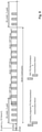
- Fig. 7 illustrates the D2D communication timing for Mode 2, autonomous scheduling, during one SA/data period, also known as SC period, Sidelink Control period.
- Fig. 8 illustrates the D2D communication timing for Mode 1, eNB-scheduled allocation during one SA/data period.
- a SC period is the time period consisting of transmission of a Scheduling Assignment and its corresponding data.
- the UE transmits after an SA-offset time, a Scheduling Assignment using the transmission pool resources for scheduling assignments for Mode 2, SA_Mode2_Tx_pool.
- the 1st transmission of the SA is followed e.g. by three retransmissions of the same SA message.
- the UE starts the D2D data transmission, i.e.
- T-RPT bitmap/pattern at some configured offset (Mode2data_offset) after the first subframe of the SA resource pool (given by the SA_offset).
- Mode2data_offset One D2D data transmission of a MAC PDU consists of its 1st transmissions and several retransmissions. For the illustration of Fig. 7 (and of Fig. 8 ) it is assumed that three retransmissions are performed (i.e. 2nd, 3rd, and 4th transmission of the same MAC PDU).
- the Mode2 T-RPT Bitmap time resource pattern of transmission (T-RPT) basically defines the timing of the MAC PDU transmission (1st transmission) and its retransmissions (2nd, 3rd, and 4th transmission).
- the UE can transmit multiple transport blocks (only one per subframe (TTI), i.e. one after the other), however to only one ProSe destination group. Also the retransmissions of one transport block must be finished before the first transmission of the next transport block starts, i.e. only one HARQ process is used for the transmission of the multiple transport blocks.
- the D2D data transmission i.e. more in particular the T-RPT pattern/bitmap
- the Mode1 T-RPT Bitmap (time resource pattern of transmission (T-RPT )) basically defines the timing of the MAC PDU transmission (1st transmission) and its retransmissions (2nd, 3rd, and 4th transmission).
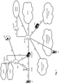
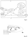
- Fig. 9 illustrates a high-level exemplary architecture for a non-roaming case, including different ProSe applications in the respective UEs A and B, as well as a ProSe Application Server and ProSe function in the network.
- the example architecture of Fig. 9 is taken from TS 23.303 v.12.4.0 chapter 4.2 "Architectural Reference Model" incorporated herein by reference.
- the ProSe function is the logical function that is used for network-related actions required for ProSe and plays different roles for each of the features of ProSe.
- the ProSe function is part of the 3GPP's EPC and provides all relevant network services like authorization, authentication, data handling etc. related to proximity services.
- the UE may obtain a specific ProSe UE identity, other configuration information, as well as authorization from the ProSe function over the PC3 reference point.
- the ProSe function consists of three main sub-functions that perform different roles depending on the ProSe feature: Direct Provision Function (DPF), Direct Discovery Name Management Function, and EPC-level Discovery Function.
- DPF Direct Provision Function
- DPF Direct Discovery Name Management Function
- EPC-level Discovery Function EPF-level Discovery Function
- UE used in said connection refers to a ProSe-enabled UE supporting ProSe functionality, such as:
- the ProSe Application Server supports the Storage of EPC ProSe User IDs, and ProSe Function IDs, and the mapping of Application Layer User IDs and EPC ProSe User IDs.
- the ProSe Application Server (AS) is an entity outside the scope of 3GPP.
- the ProSe application in the UE communicates with the ProSe AS via the application-layer reference point PC1.
- the ProSe AS is connected to the 3GPP network via PC2 reference point.
- the resource allocation method for D2D communication depends apart from the RRC state, i.e. RRC_IDLE and RRC_CONNECTED, also on the coverage state of the UE, i.e. in-coverage, out-of-coverage.
- RRC_IDLE the coverage state of the UE
- RRC_CONNECTED the coverage state of the UE
- a UE is considered in-coverage if it has a serving cell (i.e. the UE is RRC_CONNECTED or is camping on a cell in RRC_IDLE).
- IC in-coverage
- OOC out-of-coverage
- state-3 OOC and state-4 OOC are mainly to avoid potentially strong interference between D2D transmissions from out-of coverage devices and legacy E-UTRA transmissions.
- D2D-capable UEs will have preconfigured resource pool(s) for transmission of D2D SAs and data for use while out of coverage. If these out-of-coverage UEs transmit on these preconfigured resource pools near cell boundaries, then, interference between the D2D transmissions and in-coverage legacy transmissions could have a negative impact on communications within the cell.
- RAN1 introduced a mechanism where in-coverage UEs are forwarding resource pool information and other D2D related configurations to those devices just outside the coverage area (state-3 UEs).
- the Physical D2D synchronization channel (PD2DSCH) is used to carry this information about in-coverage D2D resource pools to the UEs in network proximity, so that resource pools within network proximity are aligned.
- the LCP procedure for D2D will be different than the above-presented LCP procedure for "normal" LTE data.
- the following information is taken from TS 36.321, current version 12.5.0, subclause 5.14.1.3.1 describing LCP for ProSe; it is incorporated herewith in its entirety by reference.
- the UE shall perform the following Logical Channel Prioritization procedure when a new transmission is performed:
- MAC shall consider only logical channels with the same Source Layer-2ID - Destination Layer 2 ID pairs, i.e. for one PDU, the MAC entity in the UE shall consider only logical channels of the same ProSe destination group, which basically means that the UE selects a ProSe destination group during the LCP procedure. Furthermore, in Rel-12 during one SA/data period the D2D transmitting UE can only transmit data to one ProSe destination group.
- All D2D (sidelink) logical channels e.g. STCH, Sidelink Traffic CHannel, are allocated to the same logical channel group (LCG) with LCGID set to '11' (see subclause 5.14.1.4 "Buffer Status Reporting" of TS 36.321 version 12.5.0).
- LCG logical channel group
- Rel-12 there is no prioritization mechanism for D2D (sidelink) logical channels/groups.
- all sidelink logical channels have the same priority from UE point of view, i.e. the order by which the sidelink logical channels are served is left for UE implementation.
- LCH#1, LCH#2, and LCH#3 are set up in the user equipment, and all three are associated with the same ProSe LCG (e.g. "11"). It is exemplarily assumed that LCH#1 and LCH#2 are assigned to ProSe destination group 1, and LCH#3 is assigned to ProSe destination group 2. This is depicted in Fig. 12 .
- buffer status reporting is adapted to ProSe, and at present is defined in TS 36.321 in its version 12.5.0, subclause 5.14.1.4 "Buffer Status Reporting" incorporated herein by reference.
- the (D2D) sidelink Buffer Status Reporting procedure is used to provide the serving eNB with information about the amount of sidelink data available for transmission in the sidelink buffers of the UE.
- RRC controls sidelink BSR reporting by configuring the two timers Periodic-ProseBSR-Timer and RetxProseBSR-Timer.
- Each sidelink logical channel (STCH) is allocated to an LCG with LCGID set to "11" and belongs to a ProSe Destination group.
- a sidelink Buffer Status Report shall be triggered if some particular events occurs, as specified in detail in TS 36.321, subclause 5.14.1.4.
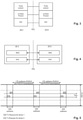
- the ProSe Buffer Status Report (BSR) MAC control element consists of one group index field, one LCG ID field and one corresponding Buffer Size field per reported D2D destination group. More in detail, for each included ProSe destination group, the following fields are defined:
- Fig. 11 shows the ProSe BSR MAC control element for even N (number of ProSe destination groups), taken from TS 36.321 subclause 6.1.3.1a.
- the transmission scheme for device-to-device communication is quite different to the normal LTE scheme, including the use of ProSe destination groups to identify the possible content of the data. Some of currently-defined mechanisms are rather inefficient.
- US2014/080494 A1 discloses a direct communication method of a terminal which includes receiving downlink control information (DCI) from an evolved node base-station (EnB), extracting D2D transmission (Tx) or reception (Rx) grant information including a D2D pairing identity (ID) given to the terminal according to each D2D pair from the DCI, and performing data transmission or reception within a counterpart terminal according to the Tx or Rx conditions set according to the D2D pairing ID.
- DCI downlink control information
- EnB evolved node base-station
- Tx transmission
- Rx reception
- ID D2D pairing identity
- Non-limiting and exemplary embodiments provide improved methods for allocating radio resources for a user equipment to perform direct communication transmission over a direct sidelink connection to one or more receiving user equipments.
- the independent claims provide non-limiting and exemplary embodiments.
- Advantageous embodiments are subject to the dependent claims.
- performing direct communication transmissions by a user equipment is improved (not only for but) particularly for scenarios in which data is available for transmission in the user equipment destined to more than one sidelink destination group.
- a new concept of sidelink grant processes is introduced so as to allow a user equipment to handle several sidelink grants at basically the same time; in other words, to enable the user equipment to transmit several direct communication transmissions at basically the same time (e.g. within the same transmission control period).
- each direct communication transmission could be configured to transmit data for the same or different sidelink destination groups.
- a sidelink grant is overwritten by a subsequently-received sidelink grant.
- a sidelink grant can still be overwritten (if a new sidelink grant for the same sidelink grant process is received) but the UE can have several valid sidelink grants at the same time (no overwriting needs to take place).
- a corresponding ID for each of the sidelink grant processes allows unambiguous association of a sidelink grant to one of the processes.
- one sidelink grant process is associated only with one (valid) sidelink grant; when acquiring a further sidelink grant associated with the same sidelink grant process, the previous sidelink grant is overwritten, as already mentioned.
- the UE allocates radio resources according to the respective sidelink grant to transmit a direct communication transmission comprising the transmission of sidelink control information and data destined to one sidelink destination group.
- the user equipment may decide to use each of the available sidelink grants for transmitting data for a different sidelink destination group. Consequently, the user equipment performs one direct communication transmission per sidelink grant process at basically the same time (i.e. within the same transmission control period), where each of the direct communication transmissions could include data destined to a different sidelink destination group.lin one implementation of the first aspect, the radio resources for the multiple direct communication transmissions performed within the same transmission control period shall not overlap in the time domain; time division is used for direct communication transmissions.
- Starvation of one sidelink destination group can be avoided according to the first aspect. Furthermore, from the perspective of the receiving user equipment, there is no change of the transmission scheme since the transmitting user equipment transmits data of only one sidelink destination group per direct communication transmission (i.e. per sidelink grant process). Correspondingly, the sidelink control information can stay the same.
- determining the sidelink destination group(s) of which data should be transmitted can be performed by the transmitting user equipment either using a common logical channel prioritization procedure so as to determine the sidelink destination group(s) for all of the acquired sidelink grants, or the transmitting user equipment uses a separate logical channel prioritization procedure for each sidelink grant.
- the principles of the first aspect are applicable to both resource allocation methods, i.e. where the user equipment requests and then receives a corresponding sidelink grant from a radio base station and where the user equipment autonomously selects a sidelink grant from suitable transmission radio resource pool(s).
- the radio base station transmits a scheduling message with the sidelink grant to the user equipment
- the sidelink scheduling message (apart from comprising e.g. information on the content of the scheduling control information to be transmitted by the user equipment and information on the radio resources to be used for transmitting the scheduling control information and data) may also identify the sidelink grant process to which the sidelink grant is to be associated. On that basis, the user equipment can then associate the received sidelink grant to the intended sidelink grant process.
- the direct communication transmission is improved by basically allowing a scheduling assignment (sidelink control information) transmitted by a user equipment to identify multiple sidelink destination groups.
- a scheduling assignment (sidelink control information) transmitted by a user equipment to identify multiple sidelink destination groups.
- data destined to a plurality of sidelink destination groups is available for transmission in the user equipment, and further that the user equipment has a sidelink grant available for performing a direct communication transmission.
- the user equipment determines at least two sidelink destination groups among the plurality the data of which shall be carried in the direct communication transmission.
- the sidelink control information relating to the direct communication transmission shall identify the determined at least two sidelink destination groups and the radio resources allocated to transmit the sidelink control information and the corresponding data destined to the determined at least two sidelink destination groups.
- the user equipment performs a direct communication transmission which may carry data for multiple sidelink destination groups.
- the sidelink control information message comprises one ID per sidelink destination group.
- the sidelink control information message comprises one sidelink ID, which is associated with multiple sidelink destination groups.
- a mapping function is to be introduced so as to establish an association between different sidelink IDs and corresponding sidelink destination groups, and corresponding information on this association needs to be provided to both transmitting and receiving user equipments. Then, the transmitting user equipment, after determining the sidelink destination groups the data of which is to be carried by the direct communication transmission, shall determine a corresponding sidelink ID based on this association such that the sidelink ID is associated with the determined sidelink destination groups. The sidelink ID can then be included in the corresponding sidelink control information, instead of the various IDs of the sidelink destination groups. At the receiving side, the receiving UE can then determine the sidelink destination groups to which the sidelink ID refers, also based on this information on the associations.
- the principles of the second aspect are applicable to both resource allocation methods, i.e. where the user equipment requests and then receives a corresponding sidelink grant from a radio base station and where the user equipment autonomously selects a sidelink grant from suitable transmission radio resource pool(s).
- the techniques disclosed here feature a method for allocating radio resources for a user equipment to perform direct communication transmissions over a direct sidelink connection to one or more user equipments in a communication system.
- At least two sidelink grant processes are provided in the user equipment for the user equipment to be able to handle at least two sidelink grants within the same transmission control period.
- Each one of the at least two sidelink grant processes is associated with an identification and can be associated with one sidelink grant.
- At least two sidelink grants are acquired, each of which is associated by the user equipment with one of the at least two sidelink grant processes.
- radio resources are allocated by the user equipment according to the respective sidelink grant to perform a direct communication transmission of sidelink control information and of data over the direct sidelink connection.
- the user equipment performs a direct communication transmission per sidelink grant process with correspondingly-associated sidelink grant within the same transmission control period.
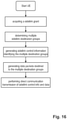
- the techniques disclosed here feature another method for allocating radio resources for a user equipment to perform direct communication transmissions over a direct sidelink connection to one or more receiving user equipments in a communication system. Data destined to a plurality of sidelink destination groups is available for transmission in the user equipment. A sidelink grant is available to the user equipment to be used for a direct communication transmission.
- the user equipment determines at least two sidelink destination groups from the plurality of sidelink destination groups as destinations of a direct communication transmission.
- the transmitting UE allocates radio resources according to the available sidelink grant to be used for the direct communication transmission.
- the transmitting UE generates a sidelink control information message identifying the determined at least two sidelink destination groups and the allocated radio resources.
- the transmitting UE performs a direct communication transmission of the generated sidelink control information message and of data destined to the determined at least two sidelink destination groups over the direct sidelink connection.
- the techniques disclosed here feature a user equipment for performing direct communication transmissions over a direct sidelink connection to one or more receiving user equipments in a communication system.
- At least two sidelink grant processes are provided in the user equipment for the user equipment to be able to handle at least two sidelink grants within the same transmission control period.
- Each one of the at least two sidelink grant processes is associated with an identification and can be associated with one sidelink grant.
- a processor of the user equipment acquires at least two sidelink grants and to associate each of the acquired at least two sidelink grants with one of the at least two sidelink grant processes.
- the processor allocates radio resources according to the respective sidelink grant to perform a direct communication transmission of sidelink control information and of data over the direct sidelink connection.
- the user equipment performs a direct communication transmission per sidelink grant process with correspondingly-associated sidelink grant within the same transmission control period.
- the techniques disclosed here feature another user equipment for performing direct communication transmissions over a direct sidelink connection to one or more receiving user equipments in a communication system.
- the transmitting user equipment comprises a buffer storing data available for transmission and destined to a plurality of sidelink destination groups.
- a sidelink grant is available to the transmitting user equipment to be used for a direct communication transmission.
- a processor of the transmitting user equipment determines at least two sidelink destination groups from the plurality of sidelink destination groups as destinations of a direct communication transmission.
- the processor allocates radio resources according to the available sidelink grant to be used for the direct communication transmission.
- the processor generates a sidelink control information message identifying the determined at least two sidelink destination groups and the allocated radio resources.
- the processor and a transmitter of the transmitting UE performs a direct communication transmission of the generated sidelink control information message and of data destined to the determined at least two sidelink destination groups over the direct sidelink connection.
- the techniques disclosed here feature a radio base station for allocating radio resources to a transmitting user equipment for the transmitting user equipment to perform direct communication transmissions over a direct sidelink connection to one or more receiving user equipments in a communication system.
- At least two sidelink grant processes are provided in the transmitting user equipment for the transmitting user equipment to be able to handle at least two sidelink grants within the same transmission control period.
- Each one of the at least two sidelink grant processes is associated with an identification and can be associated with one sidelink grant.
- a processor of the radio base station generates a sidelink grant and associates the generated sidelink grant with one of the at least two sidelink grant processes.
- the processor generates a sidelink scheduling message including an identification of the one sidelink grant process associated to the sidelink grant.
- a transmitter of the radio base station transmits the generated sidelink scheduling message to the transmitting user equipment.
- a mobile station or mobile node or user terminal or user equipment is a physical entity within a communication network.
- One node may have several functional entities.
- a functional entity refers to a software or hardware module that implements and/or offers a predetermined set of functions to other functional entities of a node or the network.
- Nodes may have one or more interfaces that attach the node to a communication facility or medium over which nodes can communicate.
- a network entity may have a logical interface attaching the functional entity to a communication facility or medium over which it may communicate with other functional entities or correspondent nodes.
- radio resources as used in the set of claims and in the application is to be broadly understood as referring to physical radio resources, such as time-frequency resources.
- direct communication transmission as used in the set of claims and in the application is to be broadly understood as a transmission directly between two user equipments, i.e. not via the radio base station (e.g. eNB).
- the direct communication transmission is performed over a "direct sidelink connection ", which is the term used for a connection established directly between two user equipments.
- D2D (Device-to-Device) communication is used or ProSe communication, or a sidelink communication.
- direct sidelink connection as used in the set of claims and in the application is to be broadly understood and can be understood in the 3GPP context as the PC5 interface described in the background section.
- sidelink grant process as used in the set of claims and in the application is to be broadly understood as a process available in a user equipment to which a sidelink grant can be associated.
- a sidelink grant process can be also broadly understood as a memory region in a user equipment where a sidelink grant or sidelink grant information is stored and maintained. Each memory region is managed by the user equipment, e.g. storing, erasing sidelink grant information or overriding stored sidelink grant information with newly received sidelink grant information.
- transmission control period as used in the set of claims and in the application is to be broadly understood as the period of time where a user equipment performs the transmission of a scheduling assignment (sidelink control information) and corresponding data.
- a “transmission control period” can also be seen as that period of time for which a sidelink grant is valid.
- the “transmission control period” can be understood as the SA/data period, or the SC (sidelink control) period.
- ProSe destination group or " sidelink destination group" used in the set of claims and in the remaining application can be understood as e.g. one Source Layer-2 ID - Destination Layer 2 ID pair defined in 3GPP LTE.
- the expressions " acquiring a (sidelink) grant ", " having a (sidelink) grant available ", " receiving a (sidelink) grant ", and similar expressions, shall be understood broadly as meaning that the (sidelink) grant is either acquired/received from the responsible radio base station (i.e. Mode1), or that the UE acquires the (sidelink) grant itself by autonomously selecting resources for a grant from suitable transmission resource pool(s) (i.e.Mode2) (i.e. the UE internally receives the grant).
- UE can transmit data only for one ProSe destination group per scheduling assignment respectively scheduling control information (SCI). More in particular for PDU(s) associated with one SCI, UE shall consider only logical channels with same Source Layer-2 ID-Destination Layer-2 ID pairs. This currently-standardized D2D transmission scheme causes several disadvantages.
- the UE can transmit data of only one ProSe destination group in one SC period, such that the data of the remaining ProSe destination group(s) is basically delayed by at least one further SC period.
- the delay could become quite significant. This is even the case, where the resources available for transmission would be enough to transmit data of more than the first-served ProSe destination group.
- the eNB might assign more D2D transmission resources (by means of the SL-grant) than the UE needs, i.e.
- the UE has not enough data in its buffer for one ProSe destination group to utilize all of the assigned radio resources. For instance, this could happen when the buffer status information received at the eNB side is not accurate, or outdated. In said case, part of the allocated resources remain unused since they cannot be used for transmission of data of another ProSe destination group.
- the following exemplary embodiments are conceived by the inventors to mitigate the problems explained above.
- ProSe-enabled UEs i.e. D2D transmissions directly between UEs without the detour via the eNodeB.
- the UEs shall have data destined to a plurality of sidelink destination groups (i.e. ProSe destination groups) available for transmission, although the improved direct communication transmission according to the first embodiment is also applicable where only data for a single sidelink destination group is available for transmission in the UE.
- the first embodiment improves direct communication transmissions by introducing the concept of (a plurality of) sidelink grant processes in a UE to which sidelink grant(s) is assigned in a one-to-one manner.
- a UE handles a plurality of sidelink grants by operating a corresponding sidelink grant process for each sidelink grant.
- the sidelink grant process is addressed by use of a corresponding identification, exemplarily termed in the following sidelink grant process ID, which allows sidelink grants to be unambiguously assigned to a particular sidelink grant process.
- the first embodiment shall improve D2D communication by allowing a UE to have more than one valid sidelink grant at a particular point in time (e.g. within one SC period).
- a UE operating according to the first embodiment is allowed to have one valid sidelink grant per sidelink grant process such that the number of possible valid sidelink grants for an SC period for a UE is limited by the number of sidelink grant processes that a UE can operate at most.
- a UE which acquires a sidelink grant addressed to a sidelink grant process which already has a sidelink grant, overwrites the old sidelink grant with the newly-acquired sidelink grant (similar as in the presently standardized systems).
- the UE for instance may be allowed to have two sidelink grant processes at most such that the UE would be able to handle two different sidelink grants at the same time (a UE thus has two valid sidelink grants within an SC period).
- the sidelink grant process ID could have a size of one bit so as to be able to distinguish between the two sidelink grant processes.
- Other implementations of the first embodiment allow for a larger number of sidelink grant processes to be started in a UE, for instance 4, or 8 etc., which allows a UE to handle even more sidelink grants simultaneously.
- the corresponding sidelink grant process ID however would then have a size of more bits so as to be able to distinguish between the various sidelink grant processes; e.g. 2 bits for 4 total sidelink grant processes; 3 bits for 8 total sidelink grant processes; etc.
- the number of sidelink grant processes which a UE shall handle at maximum can be configured e.g. by RRC, or may be predetermined (e.g. fixed in a corresponding 3GPP standard).
- the UE will perform a D2D transmission for each sidelink grant process with a corresponding sidelink grant within the same SC period, e.g. respectively according to already-standardized concepts for performing D2D transmissions as explained in the background section.
- the UE determines one sidelink destination group and generates the corresponding transport blocks containing the data destined to the determined sidelink destination group. Radio resources are allocated for the D2D transmissions according to the respective sidelink grant.
- the UE For each sidelink grant available to the UE (i.e.
- the UE For each sidelink grant process), the UE generates corresponding sidelink control information identifying the sidelink destination group and also the allocated radio resources for the corresponding D2D transmission, and performs the D2D transmission of the sidelink control information and the corresponding data for each sidelink grant (process) using the allocated radio resources of the respective sidelink grant.
- the above described principles underlying the first embodiment entail various advantages. Already established procedures can be reused in said respect without modification. For instance, the same SCI format 0 can be used to transmit the sidelink control information since no additional information needs to be carried. Furthermore, since the D2D transmission for each sidelink grant process remains unchanged when compared to the currently standardized D2D transmissions, a receiving UE does not (and actually does not need to) distinguish between a D2D transmission performed according to the first embodiment for one sidelink grant process and a D2D transmission performed according to the current standard. Consequently, the UE behavior on the receiving side does not need to be adapted.
- the first embodiment allows transmitting more data within an SC period, thus increasing the data rate for D2D transmissions.
- the first embodiment allows transmitting data destined to several sidelink destination groups within the same SC period, by e.g. selecting a different sidelink destination group for each of the various sidelink grant processes. Therefore, starvation of particular sidelink destination groups can be avoided.
- the UE had several sidelink grants available, without paying attention on how the UE had acquired them in the first place.
- Mode 1 eNB-scheduled
- Mode 2 autonomous selection by UE
- the first embodiment is applicable to cases where each of the sidelink grants is acquired according to Mode 1 or acquired according to Mode 2; also, one sidelink grant could be scheduled by Mode 1 and another by Mode 2.
- one or more sidelink grants are received from the eNB, based on corresponding request(s) from the UE, e.g. a scheduling request or RACH procedure with corresponding buffer status information as explained in the background section.
- each sidelink grant is received in a corresponding sidelink scheduling message transmitted by the eNB to the UE, which additionally may identify the sidelink grant process to which the sidelink grant shall be assigned by the UE.
- a corresponding sidelink grant process ID as mentioned above can be included by the eNB in a corresponding field of the sidelink scheduling message, which can then be used by the UE to identify the respective sidelink grant process to which the received sidelink grant is to be assigned.
- a new DCI format (exemplarily termed DCI format 5a) can be introduced in said respect, which at least contains the sidelink grant process ID in a corresponding field.
- the amount of bits of such a new field, containing the sidelink grant process ID depends on the overall maximum number of sidelink grant processes that shall be available to the UE.
- the new sidelink grant process ID field can have 2 bits, thereby allowing distinguishing between 4 total sidelink grant processes.
- At least one or all of the further possible fields can also be foreseen for the new DCI format 5a:
- the sidelink scheduling message used for transmitting the sidelink grant is of the DCI format 5 (see background section).
- the 3GPP technical standard 36.212, current version 12.4.0, subclause 5.3.3.1.9 currently defines with respect to DCI format 5:
- zeros are appended to DCI format 5 so as to equal its payload size to that of DCI format 0 so as to facilitate blind decoding.
- these padding bits i.e. "zeros" can be reused to indicate the sidelink grant process ID.
- the new sidelink grant process ID field within a sidelink grant.
- some bits of any of the existing DCI e.g. DCI format 5
- DCI format 5 may be redefined for said purpose.
- the UE may perform several D2D transmissions within the same sidelink control period (e.g. one per sidelink grant process).
- the various D2D transmissions performed by the UE within the same sidelink control period shall not overlap in the time domain, i.e. the UE performs the D2D transmissions at different subframes.
- the radio resources used for transmitting the sidelink control information messages, taken from the corresponding transmission pools shall not overlap in time.
- the T-RPT patterns defining the timing of the MAC PDU's first transmission and its retransmissions shall be selected accordingly so as to avoid that the data transmissions of the two D2D transmissions overlap in time.
- SCI Scheduling control info
- the eNodeB determines non-overlapping T-RPT patterns and transmission resources for SCI and informs same to the UE in the respective sidelink scheduling messages.
- the UE itself when selecting the resources from the corresponding pools, shall take care that non-overlapping radio resources are selected for the various D2D transmissions, respectively the SCI and the data.
- SA_offsets can be defined for each sidelink grant process.
- the SA_offset is a parameter defining the start of the D2D transmission (see Fig. 7 and 8 ) thus influencing the start of the SCI transmission and in turn the data transmission.
- Mode-2-scheduled data transmission a different Mode2data_offset value can be used for the different sidelink grant processes, which would allow that the data transmission would not overlap in time, even when using the same T-RPT bitmaps for the data transmission of the various D2D transmissions.
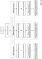
- Fig. 13 is a sequence diagram for a UE operation to perform D2D transmissions according to the first embodiment.
- the concept as shown in Fig. 13 is basically equally applicable for Mode 1- and Mode-2-scheduled D2D transmission, the specifically-depicted order of steps is rather applicable to Mode 1 (eNB-scheduled scenarios) where a UE receives a sidelink grant from the eNB.
- the UE may first select the sidelink destination group(s) for which data is to be transmitted, after which the UE then acquires the corresponding (various) sidelink grants by autonomously selecting from appropriate transmission radio resource pool(s). Based on the thus acquired sidelink grant, the sidelink control information and the corresponding sidelink data is generated for performing the D2D transmission.
- N sidelink grant processes are assumed in this exemplary scenario which are available in the UE so as to handle corresponding sidelink grants; N is ⁇ 1 but ⁇ max. no of sidelink grant processes.
- N shall not be the maximum number of sidelink grant processes that can be configured for a UE, but rather the number of sidelink grant processes which are currently "active" for respectively handling a previously acquired sidelink grant; i.e. the UE acquired and sidelink grants, one for each of the N sidelink grant processes.
- Fig. 13 illustrates that the D2D transmission for each sidelink grant process are independent from one another, although they take place at basically the same time such that the D2D transmissions are performed within the same SC period.
- Fig. 14 in turn illustrates the D2D communication timing for a Mode 1-scheduled scenario during one SC period according to the first embodiment.
- Fig. 14 is based on the illustration used already in Fig. 8 , similarly indicating an SA-offset time, after which the SC period begins with transmission of a scheduling assignment (sidelink control information) using corresponding transmission pool resources, as indicated in the sidelink grant received from the eNodeB.
- a scheduling assignment sidelink control information
- the first transmission of the SCI is followed by three retransmissions of the same SCI message.
- the UE begins the D2D data transmission in the next uplink subframe.
- a MAC PDU is transmitted in its first transmission and retransmission(s) as configured by the T-RPT (time resource pattern of transmission).
- a UE performs a D2D transmission for each sidelink grant process (i.e. in this case for each of the two sidelink grants) within basically the same sidelink control period (e.g. starting at the same time after the SA_offset and lasting for the length of the sidelink control period).
- This is accordingly depicted in Fig. 14 showing two D2D transmissions of a scheduling assignment and the corresponding data performed by a transmitting user equipment.
- the upper D2D transmission is assumed to be destined to a different sidelink destination group than the lower one (however, the two D2D transmissions could carry data for the same sidelink destination group).
- the radio resources used for transmitting the several D2D transmissions shall not overlap in time.
- the eNodeB selected, and correspondingly indicated in the sidelink grants non-overlapping radio resources in the time domain for the transmission of the two scheduling assignments.
- the eNodeB selected, and correspondingly indicated in the sidelink grants non-overlapping radio resources in the time domain for the transmission of the respective data and the corresponding control information (SCI) of the two D2D transmissions.
- the respective T-RPT bitmaps are different between the two D2D transmissions.
- Fig. 15 illustrates the D2D communication timing for a Mode 2-scheduled scenario during one SC period according to the first embodiment.
- Fig. 15 is based on the illustration used already in Fig. 7 of the background section. Different to the scenario of Fig. 14 , no sidelink grant is received from the radio base station, rather it is assumed that the two sidelink grants are autonomously selected by the UE. As with the illustration of Fig. 14 , the radio resources for transmitting the sidelink control information and the data for the two D2D transmissions are not overlapping in time.
- the UE selects corresponding non-overlapping resources in the time domain from the SA_mode2_Tx_pool for the transmission of the sidelink control information, and also selects appropriately different T-RPT bitmaps for the transmission of the data and transmission resources for the corresponding control information (SCI) for the two D2D transmissions.
- SCI control information
- Fig. 14 and Fig. 15 illustrate scenarios in which the available sidelink grants are all either eNodeB scheduled or autonomously selected. However, a UE may have also valid sidelink grant(s) according to Mode 1 and Mode 2 at the same time.
- the UE determines the sidelink destination groups to which D2D transmissions are to be performed in the same SC period.
- the step of determining the sidelink destination groups is performed by use of logical channel prioritization, LCP, procedure(s).
- one LCP procedure is performed for each sidelink grant process (or valid sidelink grant), such that the UE selects the sidelink destination group for each sidelink grant process separately from one another.
- the order in which sidelink logical channels are treated is not specified and left to the implementation of the UE, i.e. the selection of the destination group and the order in which the sidelink logical channels belonging to the selected destination group are treated is not specified and not subject to some prioritization mechanism.
- the assumption for this implementation is however that each sidelink destination group is associated with a corresponding priority.
- the UE would perform a LCP procedure for each sidelink grant process separately. More in particular. the UE would perform the LCP procedures sequentially, i.e.
- the UE would select the sidelink destination group with the highest corresponding priority having data available. Therefore, in the case that UE has data available for transmission for two different destination groups and after having performed the first LCP procedure (according to the first sidelink grant) there is still data for the highest priority sidelink destination group in its buffer, the UE would select again the same sidelink destination group within the second LCP procedure.
- a common LCP procedure is performed by the UE for all the sidelink grant processes (or valid sidelink grants), such that the UE selects the sidelink destination groups for all the sidelink grant processes in an interdependent manner.
- each destination group is associated with a corresponding priority.
- the selection of the destination groups is performed in a decreasing order of the destination group priority.
- the first sidelink grant is used for the destination group with the highest priority among them.
- the second sidelink grant is used for the destination group with the second-highest priority among them, even if there is remaining data available to be transmitted to the destination group with the highest priority among them. And so on for any further destination groups and sidelink grants.
- the second embodiment's main concept is different from that of the first embodiment.
- similar assumptions can be made for the scenario(s) with which the underlying principles of the second embodiment will be explained.
- a ProSe-enabled UE is assumed which is thus able to perform D2D transmission(s) directly with other UE(s) without the detour via the eNodeB.
- the UE shall have data destined to a plurality of sidelink destination groups available for transmission, although the improved D2D transmissions according to the second embodiment are equally applicable where data for only a single sidelink destination group is available for transmission in the UE.
- D2D transmissions are improved by enhancing the sidelink control information to be able to identify multiple sidelink destination groups, instead of only one.
- a D2D transmission performed by a UE may carry data for multiple sidelink destination groups as identified by the corresponding sidelink control information.
- the radio resources for performing the D2D transmission are defined by a sidelink grant available to the UE.
- the UE has only one valid sidelink grant per SC period, in a similar manner as currently defined in the 3GPP standard; thus no changes are necessary in said respect according to the second embodiment.
- the UE which has data available for a plurality of sidelink destination groups, selects (at least two) particular sidelink destination groups from among them, and then continues to generate appropriate sidelink control information identifying the selected multiple destination groups and to generate the corresponding data packets for the D2D transmission, wherein the data packets carry data of the several determined sidelink destination groups.
- the UE can transmit data of different sidelink destination groups within one D2D transmission, within one SC period, where the different sidelink destination groups are identified by the sidelink control information transmitted at the beginning of the D2D transmission.
- Fig. 16 illustrates a sequence diagram of the UE behavior when performing a D2D transmission according to the second embodiment, including the above-mentioned steps of: acquiring a sidelink grant, determining multiple sidelink destination groups, generating sidelink control information identifying the multiple sidelink destination groups, generating data packets carrying data destined to the multiple selected sidelink destination groups and finally performing the D2D transmission of the generated sidelink control information and corresponding data destined to the multiple sidelink destination groups.
- the second embodiment is not limited to this particular order, but other suitable orders are equally possible.
- the step of determining the various sidelink destination groups can be performed before the step of acquiring a sidelink grant; or the steps of generating sidelink control information and the data packets can be exchanged.
- Fig. 17 in turn illustrates the D2D communication timing for a Model-scheduled scenario during one SC period according to the second embodiment.
- the exemplary illustration in Fig. 17 is based on the illustration already used in the background section according to Fig. 8 .
- each of the MAC PDUs (and its respective retransmissions) may carry data destined to a different sidelink destination group (in this particular example of Fig. 17 data destined to three different sidelink destination groups is transmitted within the SC period), whereas in currently standardized systems according to Fig. 8 the MAC PDUs would carry data for the same sidelink destination group (although the actual data within the various MAC PDUs would be different from one to the next).
- the first MAC PDU (and its retransmissions) could carry data destined to the first sidelink destination group
- the second MAC PDU (and its retransmissions) could carry data destined to the second sidelink destination group
- the third MAC PDU (and its retransmissions) could carry data again destined to the first sidelink destination group, and so on.
- the scheduling assignment (sidelink control information) transmitted at the beginning of the sidelink control period (and its retransmissions) identifies the three sidelink destination groups.
- the sidelink control information message may either directly identify the multiple sidelink destination groups (i.e. by including multiple corresponding IDs) or indirectly (i.e. by including one ID being in turn associated with multiple sidelink destination groups) as will be explained in detail below.
- the sidelink control information message transmitted as part of the D2D transmission comprises one sidelink destination group ID per determined sidelink destination group.
- the sidelink control information message directly identifies the sidelink destination groups by including their corresponding identifications.
- the sidelink control information message could include two or more sidelink destination group IDs.
- a new sidelink control information format (exemplarily termed in the following SCI format 1) can be defined which comprises several fields for the sidelink destination group IDs.
- the new SCI format 1 can be based on the already standardized SCI format 0 (as defined in 3GPP TS 36.212, current version 12.4.0, subclause 5.4.3.1.1), but additionally allowing for several sidelink destination group IDs (termed in the standard, "group destination ID").
- new SCI format 1 would thus include, in correspondence with the already standardized SCI format 0 of TS 36.212, one or more of the following fields:
- the new SCI format 1 would have 16 bits available so as to include two group destination IDs (i.e. corresponding to the two sidelink destination group IDs).
- the new SCI format 1 would have 16 bits available so as to include two group destination IDs (i.e. corresponding to the two sidelink destination group IDs).
- more bits have to be provided in said respect (e.g. 24 bits for 3 different sidelink destination group IDs, 32 bits for 4 different sidelink destination group IDs etc.).
- the receiving UE shall be aware to which sidelink destination group ID the corresponding transport blocks in the D2D transmission refer; put differently, the receiving UE shall know which of the transport blocks carries data of which sidelink destination group identified in the SCI. This could be exemplarily done by a predetermined unambiguous relationship (i.e. a rule) between the order of the sidelink destination group IDs in the SCI and the order of the corresponding transport blocks in the subsequent part of the D2D transmission.
- the order of the (multiple) group destination IDs (i.e. the sidelink destination group IDs) within the SCI may correspond to the order of the corresponding transport blocks (i.e.
- transport blocks carrying data for the respective sidelink destination groups) as transmitted in the D2D transmission For example, when the first group destination ID in the SCI points to destination A and the second group destination ID points to destination B, then, in case there are two transport blocks transmitted within the SC period, the first transport block contains data destined to group A and the second transport block contains data destined to group B. In case there would be three transport blocks transmitted within the SC period, the third transport block would for example contain again data destined to group A, and so on.
- a receiving UE is according to some predefined rule aware of the group destination IDs of the corresponding transport blocks within a SCI period.
- a receiving UE When implementing same in the currently-specified 3GPP environment, a receiving UE knows, based on the group destination IDs within the SCI and the predefined rules, the 8 least significant bits (LSBs) of the Destination Layer-2 ID(s) of the data within the transport blocks. Consequently, the UE can filter the D2D transmission, particularly the MAC PDUs, depending on the sidelink destination group for which it is interested such that the receiving UE only decodes those MAC PDUs that contain data of sidelink destination groups that it is indeed interested in. More in detail, if the DST field of the decoded MAC PDU subheader is equal to the 16 MSB of any of the Destination Layer-2 ID(s) of the UE, the PDU will be further processed in the UE.
- the DST field of the decoded MAC PDU subheader is equal to the 16 MSB of any of the Destination Layer-2 ID(s) of the UE, the PDU will be further processed in the UE.
- the DST field of the MAC PDU subheader contains the 24 MSB, e.g. the complete 24 bits, of the Destination Layer-2 ID. Based on these 24bits in the MAC subheader, a receiving UE can unambiguously identify the Destination Layer-2 ID of the data in a transport block and thus perform the MAC filtering. In this case, the order of the group destination IDs within the SCI does not need to correspond to the order of the corresponding transport blocks as transmitted in the D2D transmission.
- the first transport block could contain data destined to group B and the second transport block contains data destined to group A.
- a receiving UE could unambiguously perform the filtering, i.e. decode only those packets which the receiving UE is interested in based on the Destination Layer-2 ID.
- the sidelink control information message transmitted as part of the D2D transmission comprises only a single ID, which in turn however is associated with the multiple determined sidelink destination groups. Consequently, instead of directly identifying the sidelink destination groups by including their corresponding identifications, the sidelink destination groups are indirectly identified by a suitable ID which at the receiver side can be associated again to the multiple sidelink destination groups.
- the second alternative implementation introduces a new ID, which is transmitted instead of the sidelink destination group ID and which is associated with multiple sidelink destination groups.
- this new ID exemplarily termed in the following Broadcast ID, groups various sidelink destination groups together according to a Many-to-one mapping such that one Broadcast ID is associated with at least two different sidelink destination groups.
- This new mapping function can be performed by a suitable node in the core network, for instance the ProSe server function. Accordingly, the ProSe server function can perform such a mapping function so as to associate several sidelink destination groups to each Broadcast ID.
- the corresponding mapping information i.e.
- the Broadcast IDs and corresponding associated sidelink destination groups is then provided to the UEs, and optionally also to the eNodeBs.
- the provision of this information can be for example performed using RRC signaling, or being broadcast in the system information by the various eNodeBs.
- this new Broadcast ID is of the same size as the sidelink destination group ID normally used to identify sidelink destination group in the sidelink control information, i.e. 8 bits (see background section) such that the already defined sidelink control information format 0 can be reused without adaptation.
- the new broadcast ID can be of a different size, e.g. larger, than a normally used sidelink destination group ID, in which case a new sidelink control information format is needed to carry same.
- the UE after determining the multiple sidelink destination groups for which data is to be transmitted in the D2D transmission according to the valid sidelink grant, needs to also determine a corresponding Broadcast ID that is associated to those multiple determined sidelink destination groups.
- the UE then can include the determined Broadcast ID into the sidelink control information of the D2D transmission, instead of including one or the multiple IDs of the sidelink destination groups.
- UEs that receive the D2D transmission comprising the sidelink control information with the Broadcast ID determine the multiple sidelink destination groups from the received Broadcast ID and based on stored mapping information previously received from e.g. the ProSe server function.
- the sidelink control information message can include appropriate information (such as a flag) as to whether the sidelink control information message comprises the new Broadcast ID or a normal sidelink destination group ID.
- appropriate information such as a flag
- a transmitting UE sets a corresponding flag value depending on whether it includes a Broadcast ID (when data of several sidelink destination groups is to be transmitted within the D2D transmission) or a normal sidelink destination group ID (when data of only one sidelink destination group is to be transmitted within the D2 the transmission).
- a receiving UE takes this flag value into account when determining to which sidelink destination group(s) the received D2D is actually destined.
- a UE which has data available for transmission for several sidelink destination groups determines for which of those multiple sidelink destination groups data shall be transmitted with the next D2D transmission.
- the corresponding sidelink control information message is then generated so as to identify the determined multiple sidelink destination groups; be it by including several IDs according to the first alternative implementation described above, or by including a single suitable Broadcast ID according to the second alternative implementation described above.
- a UE generates the corresponding data packets (i.e. MAC PDUs) destined to the multiple sidelink destination groups for transmission as part of the D2D transmission within the SC period.
- the first transport block (MAC PDU) generated by the UE for the SC period could carry data destined for a first sidelink destination group
- the second transport block generated by the UE within the SC period could carry data destined for a second sidelink destination group and so on. This is readily apparent from the illustration in Fig. 17 .
- the number of sidelink destination groups for which data can be transmitted by a D2D transmission within one SC period also depends on the length of the SC period and/or the T-RPT patterns given by the sidelink grant.
- the length of the sidelink control period in combination with the selected T-RPT bitmaps allows for three separate MAC PDUs to be transmitted within one SC period such that at most data destined for three sidelink destination groups can be transmitted by the UE.
- T-RPT patterns e.g. with less repetitions
- a corresponding operation on the receiving side allows reception of the D2D transmission with data destined to several sidelink destination groups.
- a receiving UE identifies the several sidelink destination groups from the sidelink control information message (Group destination ID) and can thus decide whether it is interested in the D2D transmission or not, i.e. whether the UE is interested in receiving data for one or more of the sidelink destination groups identified by the identifier in the SCI therein. If the UE is interested, the corresponding data within the D2D transmission is received and decoded in an appropriate manner by the receiving UE. This may include that the receiving UE determines the sidelink destination group of each of the MAC PDUs of the D2D transmission so as to decide whether it wants to receive and decode the data within the MAC PDU or not.
- a MAC header includes information on the sidelink destination group of the data which is included.
- the 16 most significant bits of the Destination Layer-2 ID are transmitted by which the receiving UE can identify the sidelink destination group.
- the SCI message as currently standardized comprises the 8 LSB of the Destination Layer2-ID, which then in combination with the 16MSBwithin the MAC header, allows the receiving UE to unambiguously identify the sidelink destination group (i.e. the Destination Layer-2 ID).
- the UE can filter the D2D transmission, particularly the MAC PDUs, depending on the sidelink destination group for which it is interested such that the receiving UE only decodes those MAC PDUs that contain data of sidelink destination groups that it is indeed interested in. More in detail, if the DST field of the decoded MAC PDU subheader is equal to the 16 MSB of any of the Destination Layer-2 ID(s) of the UE, the PDU will be further processed in the UE.
- the DST field of the MAC PDU subheader contains the 24 MSB, e.g. the complete 24 bits, of the Destination Layer-2 ID, instead of only the 16 MSB of the Destination Layer-2 ID as currently standardized.
- a receiving UE can unambiguously identify the Destination Layer-2 ID of the data in a transport block and thus perform the MAC filtering. This would be advantageous in particular for the second embodiment described above where several Group destination IDs are mapped to one Broadcast ID, since a receiving UE would not know the Group destination ID, i.e. 8 LSB of the Destination Layer-2 ID of the corresponding transport blocks within a SC period.
- the DST field in the MAC PDU subheader only contains the 16MSB of the Destination Layer-2 ID, a receiving UE cannot unambigiously identify the complete Destination Layer -2 ID of the data of a transport block (since it does not know the 8LSB of the Destination Layer-2 ID (Group destination ID)).
- the second embodiment is applicable to both Mode1-acquired sidelink grants and Mode2-acquired sidelink grants.
- the sidelink grant was received from the eNodeB, e.g. based on a corresponding request from the UE, for instance a scheduling request or RACH procedure with corresponding buffer status information as an explained in the background section.
- the UE determines the multiple sidelink destination groups to which the D2D transmission is to be performed within the SC period without giving any further details.
- the step of determining the multiple sidelink destination groups can be performed by the UE by use of logical channel prioritization, LCP, procedure(s). In particular, during the LCP procedure the UE can determine for which sidelink destination groups data is to be transmitted.
- a UE would be allowed to transmit data to different sidelink destination groups as long as the corresponding group destination ID (which is transmitted in the SCI) is the same.
- the Group destination ID which is transmitted in the SCI on the physical sidelink control channel is the 8 least significant bits (LSB) of the Destination Layer-2 ID.
- the UE multiplexes logical channels within a PDU of Source Layer-2 ID-Destination Layer-2 ID pairs where the 8LSB of the Destination Layer-2 ID is the same, the UE is allowed to transmit data to different sidelink destination groups within one SC period. This implementation actually requires no change of the currently- standardized procedure.
- a user terminal mobile terminal
- an eNodeB base station
- the user terminal and base station is adapted to perform the methods described herein, including corresponding entities to participate appropriately in the methods, such as receiver, transmitter, processors.
- a computing device or processor may for example be general purpose processors, digital signal processors (DSP), application specific integrated circuits (ASIC), field programmable gate arrays (FPGA) or other programmable logic devices, etc.
- DSP digital signal processors
- ASIC application specific integrated circuits
- FPGA field programmable gate arrays
- the various embodiments may also be performed or embodied by a combination of these devices.
- each functional block used in the description of each embodiment described above can be realized by an LSI as an integrated circuit. They may be individually formed as chips, or one chip may be formed so as to include a part or all of the functional blocks. They may include a data input and output coupled thereto.
- the LSI here may be referred to as an IC, a system LSI, a super LSI, or an ultra LSI depending on a difference in the degree of integration.
- the technique of implementing an integrated circuit is not limited to the LSI and may be realized by using a dedicated circuit or a general-purpose processor.
- a FPGA Field Programmable Gate Array
- a reconfigurable processor in which the connections and the settings of circuits cells disposed inside the LSI can be reconfigured may be used.
- the various embodiments may also be implemented by means of software modules, which are executed by a processor or directly in hardware. Also a combination of software modules and a hardware implementation may be possible.
- the software modules may be stored on any kind of computer readable storage media, for example RAM, EPROM, EEPROM, flash memory, registers, hard disks, CD-ROM, DVD, etc. It should be further noted that the individual features of the different embodiments may individually or in arbitrary combination be subject matter to another embodiment.
Landscapes
- Engineering & Computer Science (AREA)
- Computer Networks & Wireless Communication (AREA)
- Signal Processing (AREA)
- Mobile Radio Communication Systems (AREA)
Priority Applications (2)
| Application Number | Priority Date | Filing Date | Title |
|---|---|---|---|
| EP23180243.0A EP4236613A3 (en) | 2015-04-17 | 2015-04-17 | Multiple prose group communication during a sidelink control period |
| EP21213187.4A EP3986072B1 (en) | 2015-04-17 | 2015-04-17 | Multiple prose group communication during a sidelink control period |
Applications Claiming Priority (1)
| Application Number | Priority Date | Filing Date | Title |
|---|---|---|---|
| PCT/CN2015/076867 WO2016165124A1 (en) | 2015-04-17 | 2015-04-17 | Multiple prose group communication during a sidelink control period |
Related Child Applications (3)
| Application Number | Title | Priority Date | Filing Date |
|---|---|---|---|
| EP21213187.4A Division-Into EP3986072B1 (en) | 2015-04-17 | 2015-04-17 | Multiple prose group communication during a sidelink control period |
| EP21213187.4A Division EP3986072B1 (en) | 2015-04-17 | 2015-04-17 | Multiple prose group communication during a sidelink control period |
| EP23180243.0A Division EP4236613A3 (en) | 2015-04-17 | 2015-04-17 | Multiple prose group communication during a sidelink control period |
Publications (3)
| Publication Number | Publication Date |
|---|---|
| EP3284299A1 EP3284299A1 (en) | 2018-02-21 |
| EP3284299A4 EP3284299A4 (en) | 2018-12-12 |
| EP3284299B1 true EP3284299B1 (en) | 2022-02-16 |
Family
ID=57127129
Family Applications (3)
| Application Number | Title | Priority Date | Filing Date |
|---|---|---|---|
| EP23180243.0A Pending EP4236613A3 (en) | 2015-04-17 | 2015-04-17 | Multiple prose group communication during a sidelink control period |
| EP21213187.4A Active EP3986072B1 (en) | 2015-04-17 | 2015-04-17 | Multiple prose group communication during a sidelink control period |
| EP15888829.7A Active EP3284299B1 (en) | 2015-04-17 | 2015-04-17 | Multiple prose group communication during a sidelink control period |
Family Applications Before (2)
| Application Number | Title | Priority Date | Filing Date |
|---|---|---|---|
| EP23180243.0A Pending EP4236613A3 (en) | 2015-04-17 | 2015-04-17 | Multiple prose group communication during a sidelink control period |
| EP21213187.4A Active EP3986072B1 (en) | 2015-04-17 | 2015-04-17 | Multiple prose group communication during a sidelink control period |
Country Status (5)
| Country | Link |
|---|---|
| US (3) | US10869296B2 (ja) |
| EP (3) | EP4236613A3 (ja) |
| JP (1) | JP6590942B2 (ja) |
| CN (2) | CN107615844B (ja) |
| WO (1) | WO2016165124A1 (ja) |
Families Citing this family (108)
| Publication number | Priority date | Publication date | Assignee | Title |
|---|---|---|---|---|
| EP3231238B1 (en) * | 2014-12-10 | 2020-02-05 | Telecom Italia S.p.A. | Multi-band cellular network with control plane decoupled from user plane |
| CN107592984B (zh) * | 2015-05-07 | 2021-02-26 | Lg电子株式会社 | 在无线通信系统中根据基于竞争的调度请求执行副链路传输的方法和设备 |
| US10064212B2 (en) | 2015-05-14 | 2018-08-28 | Blackberry Limited | Transmitting a scheduling request for a device-to-device transmission |
| US9942917B2 (en) * | 2015-05-14 | 2018-04-10 | Blackberry Limited | Allocating resources for a device-to-device transmission |
| US10412706B2 (en) * | 2015-05-15 | 2019-09-10 | Kyocera Corporation | Establishing data relay operation between a relay user equipment (relay-UE) device and an out-of-coverage user equipment (UE) device |
| EP3326402A4 (en) * | 2015-07-22 | 2019-03-06 | LG Electronics Inc. | METHOD AND APPARATUS FOR ENABLING A VEHICLE UE AND A RSU UE IN A WIRELESS COMMUNICATION SYSTEM |
| CN107950047B (zh) | 2015-08-12 | 2021-02-05 | Lg电子株式会社 | 用于在d2d通信系统中执行缓冲器状态报告的方法及其装置 |
| WO2017034232A1 (en) | 2015-08-21 | 2017-03-02 | Lg Electronics Inc. | Method for triggering a bsr for sidelink data in a d2d communication system and device therefor |
| WO2017048099A1 (ko) * | 2015-09-14 | 2017-03-23 | 엘지전자 주식회사 | 무선 통신 시스템에서 v2x 단말의 메시지 송수신 방법 및 장치 |
| EP3148284B1 (en) * | 2015-09-25 | 2020-10-21 | ASUSTek Computer Inc. | Methods and apparatus for solving mismatch between sidelink buffer status report (bsr) and available sidelink transmission in a wireless communication system |
| US10716093B2 (en) * | 2015-10-02 | 2020-07-14 | Lg Electronics Inc. | Method for allocating resources for direct communication between terminals in wireless communication system and device therefor |
| EP3366074A4 (en) * | 2015-10-21 | 2019-05-01 | LG Electronics Inc. | METHOD FOR SELECTION OF PROSE DESTINATIONS OR SL ALLOCATIONS IN A D2D COMMUNICATION SYSTEM AND DEVICE THEREFOR |
| KR102594945B1 (ko) | 2015-10-29 | 2023-10-30 | 삼성전자주식회사 | 무선 통신 시스템에서 사이드링크 통신 방법 및 장치 |
| WO2017077625A1 (ja) * | 2015-11-05 | 2017-05-11 | 富士通株式会社 | 通信装置および無線通信方法 |
| EP3920625A1 (en) | 2015-11-06 | 2021-12-08 | Sun Patent Trust | Multiple sidelink control transmission during a sidelink control period |
| EP3408999B1 (en) | 2016-04-01 | 2020-09-23 | Samsung Electronics Co., Ltd. | Method and apparatus for wireless communication in wireless communication system |
| US10820370B2 (en) | 2016-05-18 | 2020-10-27 | Samsung Electronics Co., Ltd. | Method and apparatus for performing efficient layer 2 function in mobile communication system |
| WO2018030788A1 (ko) * | 2016-08-09 | 2018-02-15 | 엘지전자 주식회사 | 무선 통신 시스템에서 단말의 사이드링크 신호 송수신 방법 |
| CN107734501A (zh) * | 2016-08-11 | 2018-02-23 | 株式会社Ntt都科摩 | 发送方法、接收方法、中继设备、基站及移动台 |
| EP3509378B1 (en) * | 2016-08-30 | 2021-03-31 | LG Electronics Inc. | Method for terminal transmitting sidelink control information in wireless communication system and terminal using same |
| WO2018047401A1 (ja) * | 2016-09-09 | 2018-03-15 | 日本電気株式会社 | 無線通信のための装置、方法、及びプログラムを格納した非一時的なコンピュータ可読媒体 |
| US10440742B2 (en) | 2016-09-23 | 2019-10-08 | Qualcomm Incorporated | Dynamic grant-free and grant-based uplink transmissions |
| EP3506693B1 (en) * | 2016-09-30 | 2021-03-03 | Huawei Technologies Co., Ltd. | Resource selecting method and terminal device |
| CN109891967B (zh) * | 2016-10-26 | 2023-12-15 | Lg电子株式会社 | 感测用于无线通信系统中的终端间的直接通信的资源的方法及其装置 |
| US10999862B2 (en) * | 2016-11-02 | 2021-05-04 | Lg Electronics Inc. | Method for performing sidelink transmission in wireless communication system and apparatus therefor |
| CN109565488B (zh) * | 2016-11-03 | 2022-07-29 | 松下电器(美国)知识产权公司 | 基站、用户设备和无线通信方法 |
| KR20190067242A (ko) | 2016-11-04 | 2019-06-14 | 텔레폰악티에볼라겟엘엠에릭슨(펍) | 무선 통신 시스템에서 전송 스케줄링을 위한 방법 및 장치 |
| EP3560261B1 (en) * | 2016-12-21 | 2023-11-08 | Telefonaktiebolaget LM Ericsson (publ) | Its status indication |
| CN108260105A (zh) * | 2016-12-29 | 2018-07-06 | 华为技术有限公司 | 一种d2d通信方法及设备 |
| US11576015B2 (en) * | 2017-01-23 | 2023-02-07 | Lg Electronics Inc. | Method for transmitting signal by terminal for V2X communication in wireless communication system, and device using same method |
| KR102334627B1 (ko) * | 2017-02-06 | 2021-12-03 | 엘지전자 주식회사 | 무선 통신 시스템에서 t-rpt를 통하여 신호를 수신하는 방법 및 장치 |
| US10582413B2 (en) * | 2017-03-16 | 2020-03-03 | Ofinno, Llc | Truncated buffer status reporting |
| CN110447294B (zh) * | 2017-03-23 | 2023-06-09 | 苹果公司 | 车到车(v2v)侧链路通信中的优先消息和资源选择 |
| WO2018174661A1 (en) * | 2017-03-24 | 2018-09-27 | Samsung Electronics Co., Ltd. | Resource selection method in vehicle to everything communication and apparatus therefore |
| EP3574694A4 (en) | 2017-03-24 | 2021-04-14 | Samsung Electronics Co., Ltd. | RESOURCE SELECTION PROCEDURE IN A VEHICLE-TO-EVERYTHING COMMUNICATION AND DEVICE FOR IT |
| US11219054B2 (en) | 2017-05-05 | 2022-01-04 | Qualcomm Incorporated | Relaying in a device-to-device communication system |
| CN112564880B (zh) * | 2017-08-11 | 2022-11-01 | Oppo广东移动通信有限公司 | 数据处理方法及相关设备 |
| US11425747B2 (en) * | 2017-09-28 | 2022-08-23 | Nokia Technologies Oy | Method, apparatus, computer program product and computer program |
| CN109788453B (zh) * | 2017-11-10 | 2022-01-14 | 华为技术有限公司 | 一种应答信息的传输方法、通信设备和网络设备 |
| CN116528373A (zh) * | 2017-11-14 | 2023-08-01 | 交互数字专利控股公司 | 无线系统中的补充上行链路传输 |
| CN110120857B (zh) * | 2018-02-05 | 2022-01-28 | 中兴通讯股份有限公司 | 选择资源的方法及装置 |
| AU2019221229B2 (en) * | 2018-02-13 | 2023-04-13 | Guangdong Oppo Mobile Telecommunications Corp., Ltd. | Apparatus and method for performing vehicle to everything communication |
| WO2019157730A1 (en) * | 2018-02-14 | 2019-08-22 | Guangdong Oppo Mobile Telecommunications Corp., Ltd. | User equipment and method of wireless communication of same |
| TWI711327B (zh) * | 2018-04-03 | 2020-11-21 | 美商Idac控股公司 | 合作車間有效資源使用方法 |
| EP3794887A1 (en) * | 2018-06-28 | 2021-03-24 | Convida Wireless, Llc | Sidelink buffer status reports and scheduling requests for new radio vehicle sidelink shared channel data transmissions |
| JP2021530151A (ja) | 2018-06-28 | 2021-11-04 | コンヴィーダ ワイヤレス, エルエルシー | Nr v2xサイドリンク共有チャネルデータ送信の優先順位付けプロシージャ |
| JPWO2020008539A1 (ja) * | 2018-07-03 | 2021-07-15 | 株式会社Nttドコモ | 通信装置及び基地局 |
| CN110708150B (zh) * | 2018-07-10 | 2021-02-12 | 华为技术有限公司 | 一种通信方法及装置 |
| US20200037190A1 (en) * | 2018-07-30 | 2020-01-30 | Qualcomm Incorporated | Methods and apparatus for qos support for sidelink in network scheduled mode |
| US11601789B2 (en) | 2018-08-01 | 2023-03-07 | Intel Corporation | UE configured to determine slots and resource blocks for V2X sidelink communication based on SCI format |
| WO2020025147A1 (en) * | 2018-08-03 | 2020-02-06 | Telefonaktiebolaget Lm Ericsson (Publ) | Reference signal management for sidelink radio transmission |
| CN110830953B (zh) * | 2018-08-10 | 2022-05-13 | 华为技术有限公司 | 一种通信方法及相关设备 |
| KR102303881B1 (ko) * | 2018-08-10 | 2021-09-23 | 아서스테크 컴퓨터 인코포레이션 | 무선 통신 시스템에 있어서 디바이스-대-디바이스 리소스 풀을 선택하는 방법 및 장치 |
| CN110830954B (zh) * | 2018-08-10 | 2021-02-12 | 电信科学技术研究院有限公司 | 一种直接链路通信的方法、终端及网络设备 |
| CN110896345B (zh) * | 2018-09-13 | 2021-07-09 | 华为技术有限公司 | 发送和接收侧行链路控制信息的方法以及装置 |
| CN113660694B (zh) * | 2018-09-18 | 2024-04-12 | 华为技术有限公司 | 传输数据的方法和装置 |
| CN112369068B (zh) * | 2018-09-25 | 2022-01-04 | Oppo广东移动通信有限公司 | 资源映射方式指示方法及相关产品 |
| WO2020064643A1 (en) * | 2018-09-26 | 2020-04-02 | Fraunhofer-Gesellschaft zur Förderung der angewandten Forschung e.V. | Method for managing sidelink resources |
| US20200100048A1 (en) * | 2018-09-26 | 2020-03-26 | Qualcomm Incorporated | Transmission with indication of geographic area |
| BR112021005710A8 (pt) * | 2018-09-27 | 2023-04-11 | Fraunhofer Ges Forschung | Dispositivo móvel e método |
| KR20210064343A (ko) * | 2018-09-27 | 2021-06-02 | 콘비다 와이어리스, 엘엘씨 | NR V2X에 대한 Uu 기반 사이드링크 제어 |
| WO2020063873A1 (en) * | 2018-09-28 | 2020-04-02 | Mediatek Singapore Pte. Ltd. | Vehicle-to-everything (v2x) sidelink communications |
| CN110972304A (zh) | 2018-09-28 | 2020-04-07 | 现代自动车株式会社 | 考虑通信系统中资源占用状态的副链路通信方法及其设备 |
| CN112449763B (zh) * | 2018-09-28 | 2024-03-01 | 联发科技股份有限公司 | 新无线电移动通信中v2x侧链路资源分配的方法及装置 |
| MX2021003260A (es) * | 2018-10-02 | 2021-05-12 | Fg innovation co ltd | Comunicaciones de enlace lateral de multiples tecnologias de acceso de radio (rat). |
| WO2020087365A1 (zh) * | 2018-10-31 | 2020-05-07 | 富士通株式会社 | 边链路数据的发送和配置方法以及装置 |
| CN111148273B (zh) * | 2018-11-02 | 2022-03-08 | 华为技术有限公司 | 用于确定传输链路的方法、终端设备和无线接入网设备 |
| US11310822B2 (en) * | 2018-11-02 | 2022-04-19 | Huawei Technologies Co., Ltd. | Methods and apparatus for sidelink communications and resource allocation |
| EP3672337B1 (en) * | 2018-12-20 | 2022-02-16 | ASUSTek Computer Inc. | Method for handling sidelink feedback collision in a wireless communication system |
| CN111385885B (zh) * | 2018-12-29 | 2023-08-01 | 大唐移动通信设备有限公司 | 一种资源分配模式的确定方法、终端及网络设备 |
| CN111385844B (zh) * | 2018-12-29 | 2021-12-03 | 华为技术有限公司 | 资源配置的方法、装置及设备 |
| WO2020142995A1 (zh) * | 2019-01-10 | 2020-07-16 | 北京小米移动软件有限公司 | 确定直连链路资源的方法、装置、用户设备及基站 |
| KR102281974B1 (ko) * | 2019-01-11 | 2021-07-27 | 아서스테크 컴퓨터 인코포레이션 | 무선 통신 시스템에서 사이드링크 자원 할당 모드 구성을 위한 방법 및 장치 |
| KR20200087698A (ko) * | 2019-01-11 | 2020-07-21 | 주식회사 아이티엘 | 무선통신시스템에서 사이드링크 물리계층 세션 아이디를 결정하는 방법 및 장치 |
| US11570755B2 (en) * | 2019-01-20 | 2023-01-31 | Qualcomm Incorporated | Control forwarding techniques for wireless communications |
| US11277819B2 (en) * | 2019-01-21 | 2022-03-15 | Huawei Technologies Co., Ltd. | Method and apparatus for sidelink transmission and resource allocation |
| EP3706496B1 (en) * | 2019-01-23 | 2021-10-20 | Lg Electronics Inc. | Two-step sci transmission of nr v2x |
| CN113475158A (zh) * | 2019-02-13 | 2021-10-01 | 康维达无线有限责任公司 | 用于5g中面向连接的车辆对x(vtx)通信的装置、系统、方法和计算机可读介质 |
| WO2020168452A1 (en) * | 2019-02-18 | 2020-08-27 | Mediatek Singapore Pte. Ltd. | Control channel design for v2x communication |
| KR20200114828A (ko) | 2019-03-29 | 2020-10-07 | 삼성전자주식회사 | 무선 통신 시스템에서 사이드링크 피드백 채널의 신호 처리를 위한 방법 및 장치 |
| CN111867146B (zh) * | 2019-04-30 | 2022-07-22 | 大唐移动通信设备有限公司 | 一种标识信息发送、接收方法、设备及装置 |
| CN113796142A (zh) | 2019-05-02 | 2021-12-14 | 三星电子株式会社 | 在无线通信系统中发送和接收旁路控制信息的方法和装置 |
| US10873944B2 (en) * | 2019-05-03 | 2020-12-22 | At&T Intellectual Property I, L.P. | Forward compatible new radio sidelink slot format signalling |
| US20220182796A1 (en) * | 2019-05-21 | 2022-06-09 | Telefonaktiebolaget Lm Ericsson (Publ) | Methods and devices for enabling group transmission in communication networks |
| US11606810B2 (en) * | 2019-07-19 | 2023-03-14 | Qualcomm Incorporated | Sidelink communication resource signaling |
| EP3981216A4 (en) * | 2019-08-15 | 2022-08-17 | LG Electronics Inc. | ASSIGNMENT OF LOWER AND UPPER IDENTIFIERS FOR SIDELINK TRANSMISSION |
| CN113508549B (zh) * | 2019-08-15 | 2024-05-03 | Oppo广东移动通信有限公司 | 传输侧行数据的方法、终端设备和网络设备 |
| US20220279529A1 (en) * | 2019-09-18 | 2022-09-01 | Telefonaktiebolaget Lm Ericsson (Publ) | Apparatuses and Methods for Using Group Buffer Status Reports |
| CN114375602A (zh) * | 2019-09-30 | 2022-04-19 | 华为技术有限公司 | 通信方法及装置 |
| US11838961B2 (en) * | 2019-10-02 | 2023-12-05 | Qualcomm Incorporated | Sidelink groupcast configuration to support feedback control |
| US11558880B2 (en) * | 2019-10-24 | 2023-01-17 | Qualcomm Incorporated | Sidelink groupcast scheduling |
| US11985647B2 (en) | 2019-10-24 | 2024-05-14 | Qualcomm Incorporated | Sidelink groupcast beam training |
| US11653349B2 (en) | 2019-10-24 | 2023-05-16 | Qualcomm Incorporated | Sidelink groupcast reachability based scheduling |
| US11109363B2 (en) * | 2019-10-31 | 2021-08-31 | Asustek Computer Inc. | Method and apparatus for transmitting device-to-device sidelink report in a wireless communication system |
| US11317381B2 (en) * | 2019-10-31 | 2022-04-26 | Asustek Computer Inc. | Method and apparatus for handling device-to-device feedback transmission in a wireless communication system |
| US11032845B2 (en) * | 2019-11-05 | 2021-06-08 | Asustek Computer Inc. | Method and apparatus for transmitting sidelink measurement report in sidelink in a wireless communication system |
| WO2021091163A1 (ko) * | 2019-11-07 | 2021-05-14 | 엘지전자 주식회사 | 그룹 통신 |
| US11546937B2 (en) * | 2019-11-08 | 2023-01-03 | Huawei Technologies Co., Ltd. | System and method for reservation and resource selection for sidelink communication |
| WO2021093891A1 (en) * | 2019-11-17 | 2021-05-20 | Guangdong Oppo Mobile Telecommunications Corp., Ltd. | Sidelink security configuration procedure |
| WO2021114131A1 (zh) * | 2019-12-11 | 2021-06-17 | 华为技术有限公司 | 一种数据传输方法、终端装置和网络装置 |
| EP4072166A4 (en) * | 2019-12-20 | 2022-12-07 | Huawei Technologies Co., Ltd. | DATA TRANSMISSION METHOD, DEVICE AND SYSTEM |
| US11665701B2 (en) * | 2020-03-27 | 2023-05-30 | Qualcomm Incorporated | Sidelink feedback timing |
| US11632785B2 (en) * | 2020-06-26 | 2023-04-18 | Qualcomm Incorporated | Receive grant for a sidelink transmission |
| KR102627692B1 (ko) * | 2020-06-29 | 2024-01-23 | 아서스테크 컴퓨터 인코포레이션 | 무선 통신 시스템에서 릴레이가 사이드링크 사용자 단말(ue) 성능 정보를 보고하기 위한 방법 및 장치 |
| GB2601396A (en) * | 2020-08-07 | 2022-06-01 | Samsung Electronics Co Ltd | Improvements in and relating to Prose group management |
| EP4171151A4 (en) * | 2020-10-22 | 2023-11-29 | LG Electronics Inc. | METHOD AND APPARATUS FOR SENDING/RECEIVING A COORDINATION MESSAGE BETWEEN USER DEVICES IN NR V2X |
| US11647408B2 (en) * | 2020-12-16 | 2023-05-09 | Qualcomm Incorporated | Techniques for dynamically updating a search space of a sidelink control channel |
| CN116711379A (zh) * | 2021-01-26 | 2023-09-05 | 华为技术有限公司 | 无线通信方法、通信装置及通信系统 |
Family Cites Families (24)
| Publication number | Priority date | Publication date | Assignee | Title |
|---|---|---|---|---|
| US20100322939A1 (en) | 2007-06-21 | 2010-12-23 | Genmab A/S | Novel methods for treating egfr-associated tumors |
| WO2011021830A2 (ko) * | 2009-08-17 | 2011-02-24 | 엘지전자 주식회사 | 무선 통신 시스템에서 상향링크 제어 정보 전송을 위한 상향링크 반송파 할당 방법 및 장치 |
| US8867458B2 (en) * | 2010-04-30 | 2014-10-21 | Nokia Corporation | Network controlled device to device / machine to machine cluster operation |
| CN103139764B (zh) | 2011-12-01 | 2015-09-09 | 华为技术有限公司 | 业务调度方法及装置 |
| CN104429141B (zh) | 2012-08-03 | 2018-11-09 | 英特尔公司 | 用于d2d通信的信令和信道设计 |
| KR20140035761A (ko) * | 2012-09-14 | 2014-03-24 | 한국전자통신연구원 | 단말간 직접 통신 방법 및 이를 이용하는 단말 장치 |
| US20140177539A1 (en) * | 2012-12-21 | 2014-06-26 | Research In Motion Limited | User-equipment-managed direct device to device communications |
| US10462802B2 (en) * | 2013-08-07 | 2019-10-29 | Interdigital Patent Holdings, Inc. | Distributed scheduling for device-to-device communication |
| US10034301B2 (en) * | 2014-03-18 | 2018-07-24 | Sharp Kabushiki Kaisha | Scheduling wireless device-to-device communications |
| SG11201607760RA (en) * | 2014-03-19 | 2016-10-28 | Interdigital Patent Holdings | Device-to-device synchronization |
| JP2017523666A (ja) * | 2014-06-27 | 2017-08-17 | シャープ株式会社 | デバイス・ツー・デバイス通信のためのリソースプール・アクセス |
| KR102311755B1 (ko) * | 2014-08-06 | 2021-10-14 | 인터디지탈 패튼 홀딩스, 인크 | 디바이스-대-디바이스(d2d) 선점 및 액세스 제어 |
| US10568114B2 (en) * | 2014-09-17 | 2020-02-18 | Innovative Sonic Corporation | Method and apparatus for requesting resources in a wireless communication system |
| US9888471B2 (en) * | 2014-09-25 | 2018-02-06 | Intel Corporation | Construction of transmission patterns for D2D communication |
| KR102377440B1 (ko) * | 2014-09-26 | 2022-03-23 | 선 페이턴트 트러스트 | 디바이스 투 디바이스(d2d) 통신에 대한 개선된 자원 할당 |
| US9918266B2 (en) * | 2014-10-06 | 2018-03-13 | Telefonaktiebolaget Lm Ericsson (Publ) | Activation and deactivation of a secondary cell for device-to-device user equipment |
| US20160128082A1 (en) * | 2014-10-31 | 2016-05-05 | Asustek Computer Inc. | Method and apparatus for handling multiple d2d (device to device) grants in a sa (scheduling assignment) period in a wireless communication system |
| CN107113538B (zh) * | 2014-12-04 | 2020-06-16 | Lg 电子株式会社 | 中继d2d链路的方法和执行该方法的设备 |
| KR20170095958A (ko) * | 2014-12-31 | 2017-08-23 | 후지쯔 가부시끼가이샤 | 버퍼 상태 보고를 생성하기 위한 방법 및 장치 및 통신 시스템 |
| US10225858B2 (en) * | 2015-01-23 | 2019-03-05 | Lg Electronics Inc. | Method for selecting of sidelink grant for a D2D UE in a D2D communication system and device therefor |
| EP3051736B1 (en) * | 2015-01-30 | 2020-04-29 | Panasonic Intellectual Property Corporation of America | Prioritization in the logical channel prioritization procedure for sidelink logical channels in ProSe direct communications |
| US10225847B2 (en) * | 2015-04-10 | 2019-03-05 | Lg Electronics Inc. | Method and device for transmitting/receiving D2D signal considering priority in wireless communication system |
| EP3920625A1 (en) * | 2015-11-06 | 2021-12-08 | Sun Patent Trust | Multiple sidelink control transmission during a sidelink control period |
| EP3206452B1 (en) * | 2016-02-10 | 2019-10-16 | Panasonic Intellectual Property Corporation of America | Priority-optimized sidelink data transfer in the case of autonomous resource allocation in lte prose communication |
-
2015
- 2015-04-17 US US15/567,055 patent/US10869296B2/en active Active
- 2015-04-17 WO PCT/CN2015/076867 patent/WO2016165124A1/en active Application Filing
- 2015-04-17 EP EP23180243.0A patent/EP4236613A3/en active Pending
- 2015-04-17 EP EP21213187.4A patent/EP3986072B1/en active Active
- 2015-04-17 CN CN201580080060.1A patent/CN107615844B/zh active Active
- 2015-04-17 JP JP2017551184A patent/JP6590942B2/ja active Active
- 2015-04-17 CN CN202111219921.3A patent/CN113891299A/zh active Pending
- 2015-04-17 EP EP15888829.7A patent/EP3284299B1/en active Active
-
2020
- 2020-11-16 US US17/098,910 patent/US11690046B2/en active Active
-
2023
- 2023-05-10 US US18/315,358 patent/US20230284184A1/en active Pending
Non-Patent Citations (1)
| Title |
|---|
| None * |
Also Published As
| Publication number | Publication date |
|---|---|
| EP3284299A1 (en) | 2018-02-21 |
| WO2016165124A1 (en) | 2016-10-20 |
| EP4236613A3 (en) | 2023-10-18 |
| EP3986072A1 (en) | 2022-04-20 |
| US11690046B2 (en) | 2023-06-27 |
| JP6590942B2 (ja) | 2019-10-16 |
| EP3986072B1 (en) | 2023-08-23 |
| CN107615844A (zh) | 2018-01-19 |
| EP3284299A4 (en) | 2018-12-12 |
| CN107615844B (zh) | 2021-11-09 |
| US20230284184A1 (en) | 2023-09-07 |
| US20180139724A1 (en) | 2018-05-17 |
| US20210068081A1 (en) | 2021-03-04 |
| EP4236613A2 (en) | 2023-08-30 |
| CN113891299A (zh) | 2022-01-04 |
| JP2018512009A (ja) | 2018-04-26 |
| US10869296B2 (en) | 2020-12-15 |
Similar Documents
| Publication | Publication Date | Title |
|---|---|---|
| US11690046B2 (en) | Multiple prose group communication during a sidelink control period | |
| US11792800B2 (en) | Multiple sidelink control transmissions during a sidelink control period | |
| EP3051736B1 (en) | Prioritization in the logical channel prioritization procedure for sidelink logical channels in ProSe direct communications | |
| EP3206452B1 (en) | Priority-optimized sidelink data transfer in the case of autonomous resource allocation in lte prose communication | |
| JP7183351B2 (ja) | サイドリンク制御期間中の複数のProSeグループ通信 | |
| JP7122695B2 (ja) | サイドリンク制御期間における複数のサイドリンク制御送信 |
Legal Events
| Date | Code | Title | Description |
|---|---|---|---|
| STAA | Information on the status of an ep patent application or granted ep patent |
Free format text: STATUS: THE INTERNATIONAL PUBLICATION HAS BEEN MADE |
|
| PUAI | Public reference made under article 153(3) epc to a published international application that has entered the european phase |
Free format text: ORIGINAL CODE: 0009012 |
|
| STAA | Information on the status of an ep patent application or granted ep patent |
Free format text: STATUS: REQUEST FOR EXAMINATION WAS MADE |
|
| 17P | Request for examination filed |
Effective date: 20171016 |
|
| AK | Designated contracting states |
Kind code of ref document: A1 Designated state(s): AL AT BE BG CH CY CZ DE DK EE ES FI FR GB GR HR HU IE IS IT LI LT LU LV MC MK MT NL NO PL PT RO RS SE SI SK SM TR |
|
| AX | Request for extension of the european patent |
Extension state: BA ME |
|
| DAV | Request for validation of the european patent (deleted) | ||
| DAX | Request for extension of the european patent (deleted) | ||
| A4 | Supplementary search report drawn up and despatched |
Effective date: 20181107 |
|
| RIC1 | Information provided on ipc code assigned before grant |
Ipc: H04W 72/14 20090101AFI20181102BHEP Ipc: H04W 72/02 20090101ALN20181102BHEP Ipc: H04W 76/14 20180101ALN20181102BHEP |
|
| STAA | Information on the status of an ep patent application or granted ep patent |
Free format text: STATUS: EXAMINATION IS IN PROGRESS |
|
| 17Q | First examination report despatched |
Effective date: 20191204 |
|
| STAA | Information on the status of an ep patent application or granted ep patent |
Free format text: STATUS: EXAMINATION IS IN PROGRESS |
|
| RIC1 | Information provided on ipc code assigned before grant |
Ipc: H04W 88/04 20090101ALN20210329BHEP Ipc: H04W 72/02 20090101ALN20210329BHEP Ipc: H04W 76/14 20180101ALN20210329BHEP Ipc: H04W 72/14 20090101AFI20210329BHEP |
|
| GRAP | Despatch of communication of intention to grant a patent |
Free format text: ORIGINAL CODE: EPIDOSNIGR1 |
|
| STAA | Information on the status of an ep patent application or granted ep patent |
Free format text: STATUS: GRANT OF PATENT IS INTENDED |
|
| INTG | Intention to grant announced |
Effective date: 20210514 |
|
| RIN1 | Information on inventor provided before grant (corrected) |
Inventor name: WANG, LILEI Inventor name: BASU MALLICK, PRATEEK Inventor name: LOEHR, JOACHIM |
|
| GRAJ | Information related to disapproval of communication of intention to grant by the applicant or resumption of examination proceedings by the epo deleted |
Free format text: ORIGINAL CODE: EPIDOSDIGR1 |
|
| STAA | Information on the status of an ep patent application or granted ep patent |
Free format text: STATUS: EXAMINATION IS IN PROGRESS |
|
| REG | Reference to a national code |
Ref country code: DE Ref legal event code: R079 Ref document number: 602015077012 Country of ref document: DE Free format text: PREVIOUS MAIN CLASS: H04W0072040000 Ipc: H04W0072140000 |
|
| GRAP | Despatch of communication of intention to grant a patent |
Free format text: ORIGINAL CODE: EPIDOSNIGR1 |
|
| STAA | Information on the status of an ep patent application or granted ep patent |
Free format text: STATUS: GRANT OF PATENT IS INTENDED |
|
| INTC | Intention to grant announced (deleted) | ||
| RIC1 | Information provided on ipc code assigned before grant |
Ipc: H04W 88/04 20090101ALN20210816BHEP Ipc: H04W 72/02 20090101ALN20210816BHEP Ipc: H04W 76/14 20180101ALN20210816BHEP Ipc: H04W 72/14 20090101AFI20210816BHEP |
|
| INTG | Intention to grant announced |
Effective date: 20210901 |
|
| GRAS | Grant fee paid |
Free format text: ORIGINAL CODE: EPIDOSNIGR3 |
|
| RAP3 | Party data changed (applicant data changed or rights of an application transferred) |
Owner name: PANASONIC INTELLECTUAL PROPERTY CORPORATION OF AMERICA |
|
| GRAA | (expected) grant |
Free format text: ORIGINAL CODE: 0009210 |
|
| STAA | Information on the status of an ep patent application or granted ep patent |
Free format text: STATUS: THE PATENT HAS BEEN GRANTED |
|
| AK | Designated contracting states |
Kind code of ref document: B1 Designated state(s): AL AT BE BG CH CY CZ DE DK EE ES FI FR GB GR HR HU IE IS IT LI LT LU LV MC MK MT NL NO PL PT RO RS SE SI SK SM TR |
|
| REG | Reference to a national code |
Ref country code: GB Ref legal event code: FG4D |
|
| REG | Reference to a national code |
Ref country code: CH Ref legal event code: EP |
|
| REG | Reference to a national code |
Ref country code: DE Ref legal event code: R096 Ref document number: 602015077012 Country of ref document: DE |
|
| REG | Reference to a national code |
Ref country code: AT Ref legal event code: REF Ref document number: 1469702 Country of ref document: AT Kind code of ref document: T Effective date: 20220315 |
|
| REG | Reference to a national code |
Ref country code: IE Ref legal event code: FG4D |
|
| REG | Reference to a national code |
Ref country code: LT Ref legal event code: MG9D |
|
| REG | Reference to a national code |
Ref country code: NL Ref legal event code: MP Effective date: 20220216 |
|
| REG | Reference to a national code |
Ref country code: AT Ref legal event code: MK05 Ref document number: 1469702 Country of ref document: AT Kind code of ref document: T Effective date: 20220216 |
|
| PG25 | Lapsed in a contracting state [announced via postgrant information from national office to epo] |
Ref country code: SE Free format text: LAPSE BECAUSE OF FAILURE TO SUBMIT A TRANSLATION OF THE DESCRIPTION OR TO PAY THE FEE WITHIN THE PRESCRIBED TIME-LIMIT Effective date: 20220216 Ref country code: RS Free format text: LAPSE BECAUSE OF FAILURE TO SUBMIT A TRANSLATION OF THE DESCRIPTION OR TO PAY THE FEE WITHIN THE PRESCRIBED TIME-LIMIT Effective date: 20220216 Ref country code: PT Free format text: LAPSE BECAUSE OF FAILURE TO SUBMIT A TRANSLATION OF THE DESCRIPTION OR TO PAY THE FEE WITHIN THE PRESCRIBED TIME-LIMIT Effective date: 20220616 Ref country code: NO Free format text: LAPSE BECAUSE OF FAILURE TO SUBMIT A TRANSLATION OF THE DESCRIPTION OR TO PAY THE FEE WITHIN THE PRESCRIBED TIME-LIMIT Effective date: 20220516 Ref country code: NL Free format text: LAPSE BECAUSE OF FAILURE TO SUBMIT A TRANSLATION OF THE DESCRIPTION OR TO PAY THE FEE WITHIN THE PRESCRIBED TIME-LIMIT Effective date: 20220216 Ref country code: LT Free format text: LAPSE BECAUSE OF FAILURE TO SUBMIT A TRANSLATION OF THE DESCRIPTION OR TO PAY THE FEE WITHIN THE PRESCRIBED TIME-LIMIT Effective date: 20220216 Ref country code: HR Free format text: LAPSE BECAUSE OF FAILURE TO SUBMIT A TRANSLATION OF THE DESCRIPTION OR TO PAY THE FEE WITHIN THE PRESCRIBED TIME-LIMIT Effective date: 20220216 Ref country code: ES Free format text: LAPSE BECAUSE OF FAILURE TO SUBMIT A TRANSLATION OF THE DESCRIPTION OR TO PAY THE FEE WITHIN THE PRESCRIBED TIME-LIMIT Effective date: 20220216 Ref country code: BG Free format text: LAPSE BECAUSE OF FAILURE TO SUBMIT A TRANSLATION OF THE DESCRIPTION OR TO PAY THE FEE WITHIN THE PRESCRIBED TIME-LIMIT Effective date: 20220516 |
|
| PG25 | Lapsed in a contracting state [announced via postgrant information from national office to epo] |
Ref country code: PL Free format text: LAPSE BECAUSE OF FAILURE TO SUBMIT A TRANSLATION OF THE DESCRIPTION OR TO PAY THE FEE WITHIN THE PRESCRIBED TIME-LIMIT Effective date: 20220216 Ref country code: LV Free format text: LAPSE BECAUSE OF FAILURE TO SUBMIT A TRANSLATION OF THE DESCRIPTION OR TO PAY THE FEE WITHIN THE PRESCRIBED TIME-LIMIT Effective date: 20220216 Ref country code: GR Free format text: LAPSE BECAUSE OF FAILURE TO SUBMIT A TRANSLATION OF THE DESCRIPTION OR TO PAY THE FEE WITHIN THE PRESCRIBED TIME-LIMIT Effective date: 20220517 Ref country code: FI Free format text: LAPSE BECAUSE OF FAILURE TO SUBMIT A TRANSLATION OF THE DESCRIPTION OR TO PAY THE FEE WITHIN THE PRESCRIBED TIME-LIMIT Effective date: 20220216 Ref country code: AT Free format text: LAPSE BECAUSE OF FAILURE TO SUBMIT A TRANSLATION OF THE DESCRIPTION OR TO PAY THE FEE WITHIN THE PRESCRIBED TIME-LIMIT Effective date: 20220216 |
|
| PG25 | Lapsed in a contracting state [announced via postgrant information from national office to epo] |
Ref country code: IS Free format text: LAPSE BECAUSE OF FAILURE TO SUBMIT A TRANSLATION OF THE DESCRIPTION OR TO PAY THE FEE WITHIN THE PRESCRIBED TIME-LIMIT Effective date: 20220617 |
|
| PG25 | Lapsed in a contracting state [announced via postgrant information from national office to epo] |
Ref country code: SM Free format text: LAPSE BECAUSE OF FAILURE TO SUBMIT A TRANSLATION OF THE DESCRIPTION OR TO PAY THE FEE WITHIN THE PRESCRIBED TIME-LIMIT Effective date: 20220216 Ref country code: SK Free format text: LAPSE BECAUSE OF FAILURE TO SUBMIT A TRANSLATION OF THE DESCRIPTION OR TO PAY THE FEE WITHIN THE PRESCRIBED TIME-LIMIT Effective date: 20220216 Ref country code: RO Free format text: LAPSE BECAUSE OF FAILURE TO SUBMIT A TRANSLATION OF THE DESCRIPTION OR TO PAY THE FEE WITHIN THE PRESCRIBED TIME-LIMIT Effective date: 20220216 Ref country code: EE Free format text: LAPSE BECAUSE OF FAILURE TO SUBMIT A TRANSLATION OF THE DESCRIPTION OR TO PAY THE FEE WITHIN THE PRESCRIBED TIME-LIMIT Effective date: 20220216 Ref country code: DK Free format text: LAPSE BECAUSE OF FAILURE TO SUBMIT A TRANSLATION OF THE DESCRIPTION OR TO PAY THE FEE WITHIN THE PRESCRIBED TIME-LIMIT Effective date: 20220216 Ref country code: CZ Free format text: LAPSE BECAUSE OF FAILURE TO SUBMIT A TRANSLATION OF THE DESCRIPTION OR TO PAY THE FEE WITHIN THE PRESCRIBED TIME-LIMIT Effective date: 20220216 |
|
| REG | Reference to a national code |
Ref country code: DE Ref legal event code: R097 Ref document number: 602015077012 Country of ref document: DE |
|
| REG | Reference to a national code |
Ref country code: DE Ref legal event code: R079 Ref document number: 602015077012 Country of ref document: DE Free format text: PREVIOUS MAIN CLASS: H04W0072140000 Ipc: H04W0072200000 |
|
| PG25 | Lapsed in a contracting state [announced via postgrant information from national office to epo] |
Ref country code: AL Free format text: LAPSE BECAUSE OF FAILURE TO SUBMIT A TRANSLATION OF THE DESCRIPTION OR TO PAY THE FEE WITHIN THE PRESCRIBED TIME-LIMIT Effective date: 20220216 |
|
| REG | Reference to a national code |
Ref country code: CH Ref legal event code: PL |
|
| PLBE | No opposition filed within time limit |
Free format text: ORIGINAL CODE: 0009261 |
|
| STAA | Information on the status of an ep patent application or granted ep patent |
Free format text: STATUS: NO OPPOSITION FILED WITHIN TIME LIMIT |
|
| REG | Reference to a national code |
Ref country code: BE Ref legal event code: MM Effective date: 20220430 |
|
| 26N | No opposition filed |
Effective date: 20221117 |
|
| PG25 | Lapsed in a contracting state [announced via postgrant information from national office to epo] |
Ref country code: MC Free format text: LAPSE BECAUSE OF FAILURE TO SUBMIT A TRANSLATION OF THE DESCRIPTION OR TO PAY THE FEE WITHIN THE PRESCRIBED TIME-LIMIT Effective date: 20220216 Ref country code: LU Free format text: LAPSE BECAUSE OF NON-PAYMENT OF DUE FEES Effective date: 20220417 Ref country code: LI Free format text: LAPSE BECAUSE OF NON-PAYMENT OF DUE FEES Effective date: 20220430 Ref country code: CH Free format text: LAPSE BECAUSE OF NON-PAYMENT OF DUE FEES Effective date: 20220430 |
|
| PG25 | Lapsed in a contracting state [announced via postgrant information from national office to epo] |
Ref country code: SI Free format text: LAPSE BECAUSE OF FAILURE TO SUBMIT A TRANSLATION OF THE DESCRIPTION OR TO PAY THE FEE WITHIN THE PRESCRIBED TIME-LIMIT Effective date: 20220216 Ref country code: BE Free format text: LAPSE BECAUSE OF NON-PAYMENT OF DUE FEES Effective date: 20220430 |
|
| PG25 | Lapsed in a contracting state [announced via postgrant information from national office to epo] |
Ref country code: IE Free format text: LAPSE BECAUSE OF NON-PAYMENT OF DUE FEES Effective date: 20220417 |
|
| P01 | Opt-out of the competence of the unified patent court (upc) registered |
Effective date: 20230517 |
|
| PG25 | Lapsed in a contracting state [announced via postgrant information from national office to epo] |
Ref country code: IT Free format text: LAPSE BECAUSE OF FAILURE TO SUBMIT A TRANSLATION OF THE DESCRIPTION OR TO PAY THE FEE WITHIN THE PRESCRIBED TIME-LIMIT Effective date: 20220216 |
|
| PGFP | Annual fee paid to national office [announced via postgrant information from national office to epo] |
Ref country code: FR Payment date: 20230424 Year of fee payment: 9 Ref country code: DE Payment date: 20230420 Year of fee payment: 9 |
|
| PGFP | Annual fee paid to national office [announced via postgrant information from national office to epo] |
Ref country code: GB Payment date: 20230419 Year of fee payment: 9 |
|
| PG25 | Lapsed in a contracting state [announced via postgrant information from national office to epo] |
Ref country code: HU Free format text: LAPSE BECAUSE OF FAILURE TO SUBMIT A TRANSLATION OF THE DESCRIPTION OR TO PAY THE FEE WITHIN THE PRESCRIBED TIME-LIMIT; INVALID AB INITIO Effective date: 20150417 |
|
| PG25 | Lapsed in a contracting state [announced via postgrant information from national office to epo] |
Ref country code: MK Free format text: LAPSE BECAUSE OF FAILURE TO SUBMIT A TRANSLATION OF THE DESCRIPTION OR TO PAY THE FEE WITHIN THE PRESCRIBED TIME-LIMIT Effective date: 20220216 Ref country code: CY Free format text: LAPSE BECAUSE OF FAILURE TO SUBMIT A TRANSLATION OF THE DESCRIPTION OR TO PAY THE FEE WITHIN THE PRESCRIBED TIME-LIMIT Effective date: 20220216 |