EP3283706B1 - Konsole zur befestigung von fassadenelementen - Google Patents
Konsole zur befestigung von fassadenelementen Download PDFInfo
- Publication number
- EP3283706B1 EP3283706B1 EP15716774.3A EP15716774A EP3283706B1 EP 3283706 B1 EP3283706 B1 EP 3283706B1 EP 15716774 A EP15716774 A EP 15716774A EP 3283706 B1 EP3283706 B1 EP 3283706B1
- Authority
- EP
- European Patent Office
- Prior art keywords
- section
- sheet metal
- support
- wall
- installation
- Prior art date
- Legal status (The legal status is an assumption and is not a legal conclusion. Google has not performed a legal analysis and makes no representation as to the accuracy of the status listed.)
- Active
Links
Images




Classifications
-
- E—FIXED CONSTRUCTIONS
- E04—BUILDING
- E04B—GENERAL BUILDING CONSTRUCTIONS; WALLS, e.g. PARTITIONS; ROOFS; FLOORS; CEILINGS; INSULATION OR OTHER PROTECTION OF BUILDINGS
- E04B1/00—Constructions in general; Structures which are not restricted either to walls, e.g. partitions, or floors or ceilings or roofs
- E04B1/38—Connections for building structures in general
- E04B1/388—Separate connecting elements
-
- E—FIXED CONSTRUCTIONS
- E04—BUILDING
- E04F—FINISHING WORK ON BUILDINGS, e.g. STAIRS, FLOORS
- E04F13/00—Coverings or linings, e.g. for walls or ceilings
- E04F13/07—Coverings or linings, e.g. for walls or ceilings composed of covering or lining elements; Sub-structures therefor; Fastening means therefor
- E04F13/08—Coverings or linings, e.g. for walls or ceilings composed of covering or lining elements; Sub-structures therefor; Fastening means therefor composed of a plurality of similar covering or lining elements
-
- E—FIXED CONSTRUCTIONS
- E04—BUILDING
- E04F—FINISHING WORK ON BUILDINGS, e.g. STAIRS, FLOORS
- E04F13/00—Coverings or linings, e.g. for walls or ceilings
- E04F13/07—Coverings or linings, e.g. for walls or ceilings composed of covering or lining elements; Sub-structures therefor; Fastening means therefor
- E04F13/08—Coverings or linings, e.g. for walls or ceilings composed of covering or lining elements; Sub-structures therefor; Fastening means therefor composed of a plurality of similar covering or lining elements
- E04F13/0801—Separate fastening elements
- E04F13/0803—Separate fastening elements with load-supporting elongated furring elements between wall and covering elements
- E04F13/0805—Separate fastening elements with load-supporting elongated furring elements between wall and covering elements with additional fastening elements between furring elements and the wall
-
- E—FIXED CONSTRUCTIONS
- E04—BUILDING
- E04F—FINISHING WORK ON BUILDINGS, e.g. STAIRS, FLOORS
- E04F13/00—Coverings or linings, e.g. for walls or ceilings
- E04F13/07—Coverings or linings, e.g. for walls or ceilings composed of covering or lining elements; Sub-structures therefor; Fastening means therefor
- E04F13/08—Coverings or linings, e.g. for walls or ceilings composed of covering or lining elements; Sub-structures therefor; Fastening means therefor composed of a plurality of similar covering or lining elements
- E04F13/0801—Separate fastening elements
- E04F13/0832—Separate fastening elements without load-supporting elongated furring elements between wall and covering elements
- E04F13/0833—Separate fastening elements without load-supporting elongated furring elements between wall and covering elements not adjustable
- E04F13/0839—Separate fastening elements without load-supporting elongated furring elements between wall and covering elements not adjustable the fastening elements situated at the corners of the covering elements, not extending through the covering
-
- E—FIXED CONSTRUCTIONS
- E04—BUILDING
- E04F—FINISHING WORK ON BUILDINGS, e.g. STAIRS, FLOORS
- E04F13/00—Coverings or linings, e.g. for walls or ceilings
- E04F13/07—Coverings or linings, e.g. for walls or ceilings composed of covering or lining elements; Sub-structures therefor; Fastening means therefor
- E04F13/08—Coverings or linings, e.g. for walls or ceilings composed of covering or lining elements; Sub-structures therefor; Fastening means therefor composed of a plurality of similar covering or lining elements
- E04F13/0801—Separate fastening elements
- E04F13/0832—Separate fastening elements without load-supporting elongated furring elements between wall and covering elements
- E04F13/0857—Supporting consoles, e.g. adjustable only in a direction parallel to the wall
-
- E—FIXED CONSTRUCTIONS
- E04—BUILDING
- E04B—GENERAL BUILDING CONSTRUCTIONS; WALLS, e.g. PARTITIONS; ROOFS; FLOORS; CEILINGS; INSULATION OR OTHER PROTECTION OF BUILDINGS
- E04B1/00—Constructions in general; Structures which are not restricted either to walls, e.g. partitions, or floors or ceilings or roofs
- E04B1/38—Connections for building structures in general
- E04B1/388—Separate connecting elements
- E04B2001/389—Brackets
-
- E—FIXED CONSTRUCTIONS
- E04—BUILDING
- E04B—GENERAL BUILDING CONSTRUCTIONS; WALLS, e.g. PARTITIONS; ROOFS; FLOORS; CEILINGS; INSULATION OR OTHER PROTECTION OF BUILDINGS
- E04B2103/00—Material constitution of slabs, sheets or the like
- E04B2103/06—Material constitution of slabs, sheets or the like of metal
Definitions
- the invention relates to a wall bracket for fixing facade elements, in particular for fastening wall or ceiling panels of particular curtain, ventilated facades, with a wall mounting portion, which is designed for mounting the console on a building wall, and with a facade mounting portion, for mounting of support - And mounting profiles is formed.
- Such consoles are widely known from the prior art.
- FIG. 1 shows the EP 0 901 549 B1 a wall support for facade substructures with a mounting leg for mounting the wall support on a load-bearing wall and a vertically extending support leg, wherein the support leg has a leg flap for clamping a support profile.
- the EP 2 354 368 A2 of the DE 10 2009 030 635 A1 , of the DE 30 05 315 A1 and the FR 2 924 138 A1 wall brackets with features of the preamble of claim 1 are known.
- the invention therefore has the task of providing a console, with which an attachment of support or mounting profiles on a building wall in a simple and safe way is possible.
- a console having the features of claim 1.
- the facade fastening section has a first connection section for horizontal mounting of mounting or mounting profiles and a second connection section for vertical mounting of mounting or mounting profiles, which is arranged perpendicular to the first connection section.
- the wall mounting portion preferably has at least one, preferably two or more mounting holes arranged one above the other, by means of which the wall mounting portion can be fastened to a building wall, for example screwed.
- a first advantageous development of the console provides that the first and second connection portion are arranged perpendicular to a contact surface of the wall mounting portion, which is designed for mounting on a building wall.
- the abutment surface is preferably arranged in a plane which is arranged perpendicular to the two planes in which the connection sections are respectively arranged.
- connection portions are arranged at a free end of the console, which faces away from the wall attachment portion. It is particularly preferred when the wall mounting portion and the facade mounting portion are integrally connected to each other like a carrier.
- connection sections each have at least one fixed point and one floating point at the free end for mounting support or mounting profiles.
- a fixed point a circular bore is provided, by means of such a fixed point the Main load, namely arranged on a variety of consoles facade weight can be worn.
- a floating point a slot is provided, which can be derived by means of such a Gleit Vietnameses caused by the wind, acting on a building facade suction and pressure forces.
- console is designed as a sheet metal bent part. It can be provided on the one hand, that the sheet is cut or punched in a first step by means of a laser and then in a second step, a cut-out development of the console is folded.
- the sheet thickness is preferably selected in a range between 1 and 4mm.
- the choice of the sheet thickness is preferably carried out in each case adapted to the static requirement. Be particularly advantageous, it has also been proven to produce the console preferably made of stainless steel, since stainless steel, in contrast to aluminum has a lower thermal conductivity and thus proves positive for a heat decoupling of the facade of a building wall. However, it is also conceivable to manufacture the console from other materials such as aluminum or other steel alloys.
- the console has at least one, preferably two claw-like sheet metal tabs in the region of the contact surface of the wall fastening section.
- the sheet metal tab is arranged in a plane which is arranged parallel to the plane of the contact surface. It is also conceivable that the sheet metal tab is arranged in the plane of the contact surface.
- thermocouple for thermal insulation against a building wall, which has a lower heat transfer coefficient than the Has wall attachment portion and which is designed such that it can be clipped onto the contact surface by means of the claw-like metal tabs. It is particularly preferred if the thermocouple is made of a plastic, for example of polyamide.
- the facade mounting portion has a first sheet metal portion disposed in the plane of the first abutment portion and a second sheet metal portion disposed in the plane of the second abutment portion, the first sheet metal portion and the second Sheet metal section are integrally connected.
- the first sheet metal section can consequently be arranged perpendicular to the second sheet metal section, wherein the sheet metal is preferably bent at an angle of approximately 90 °.
- the second sheet metal section has a maximum width which is greater than a maximum width of the first sheet metal section, and if the second sheet metal section has a minimum width which is greater than a minimum width of the first sheet metal section. Since the first sheet metal section is arranged in a plane with the first contact section, which is provided for mounting horizontally arranged support or mounting profiles, and the second sheet metal section is arranged in a plane with the second contact section, for mounting vertically arranged support or Mounting profiles is arranged, a larger moment of resistance against bending can be provided by the always larger width of the second sheet metal section.
- the console is formed in the region of the contact surface of the wall mounting portion as a double-layered sheet metal.
- the wall fastening section has an upper sheet metal section and a lower sheet metal section, wherein the upper sheet metal section forms the contact surface. It is particularly advantageous if the claw-like sheet metal tab in the lower sheet metal section ie in the im Assembled state of the building wall facing away from sheet metal section is arranged so that the upper sheet metal section can be additionally supported by means of the sheet metal tab.
- the first sheet metal section of the facade fastening section is integrally connected to the upper sheet metal section and that the second sheet metal section of the facade fastening section is integrally connected to the lower sheet metal section.
- the sheet metal sections are connected to each other at an angle of 90 °, for example, by bending.
- the contact surface has a height which is greater than a maximum width of the contact surface.
- the height of the contact surface preferably corresponds to the maximum width of the second sheet metal section. If the contact surface has a greater height than width, a large moment of resistance to bending can be achieved according to the configuration of the sheet metal sections of the facade fastening section.
- the console is integrally formed. It is advantageously provided that the facade mounting portion and the wall mounting portion are integrally formed. This is advantageous because a one-piece console is particularly inexpensive to produce.
- the console is made of sheet metal, in particular made of stainless steel.
- the console has a tie rod, wherein the tie rod has a connectable to the facade attachment portion connecting portion and a connecting portion facing away from the mounting portion for mounting on a wall.
- the tie rod is designed such that it can be arranged centrally above the facade fastening section on a building wall so that bending moments acting on the facade fastening section can be diverted toward the building wall.
- the tie rod for mounting on a building wall has a loop-like mounting portion. The provision of a tie rod has proved to be particularly advantageous when the wall mounting portion only a mounting hole is provided.
- the facade fastening section has a mounting opening for the tie rod. It is particularly advantageous if the mounting hole is keyhole-shaped and when the connecting portion of the tie rod arrow-shaped such that it can be secured against rotation by pulling in the mounting hole. Thus, a simple and tool-free attachment of the tie rod on the facade mounting portion can be made possible.
- FIGS. 1 to 5 a first embodiment of a console 10 according to the invention is shown.
- the console 10 is in FIG. 1 in a first oblique view and in FIG. 2 in a second oblique view looking in the direction of arrow 12 in FIG. 1 shown.
- the console 10 is formed as a multi-part bent sheet metal part made of stainless steel.
- the bracket 10 has a wall attachment portion 14 and a facade attachment portion 16.
- the wall mounting portion 14 is formed for mounting the bracket 10 on a building wall, not shown, by means of the mounting hole 18 and in the Figures 3 and 4 shown alone in two different oblique views.
- the mounting hole 18 is arranged in a contact surface 20 of the wall mounting portion 14, which is designed for mounting on a building wall.
- the wall mounting portion 14 is formed as a sheet metal angle, wherein a leg 22 is arranged at an angle of about 90 ° to the contact surface 20.
- the wall mounting portion 14 has in the region of the contact surface on two claw-like sheet metal tabs 24, which are arranged in a plane with the contact surface 20 and thus widen the contact surface 20.
- the metal tabs 24 are adapted to be in the FIGS. 1 and 2 shown thermocouple 26 made of polyamide or a plastic with a low heat transfer coefficients aufklipsen on the metal tabs 24 and on the wall mounting portion 14 so that a heat decoupling of the wall mounting portion 14 can be made from the building wall, not shown.
- the wall mounting portion 14 On the side facing away from the contact surface 20, the wall mounting portion 14 has a center mark 27 for aligning the console 10 on a wall.
- a recess 30 is introduced on an upper side 28, which is formed so that the leg 22 on the upper side 28, two projections 32, 34 forms.
- the projection 34 has on the upper side 28 on its projection 32 facing the end of a nose 36 which extends in the direction of the projection 32.
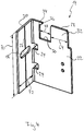
- the facade mounting portion 16 is in isolation in FIG. 5 shown.
- the facade fastening portion 16 has at its free end 38 a first connection portion 40 for horizontal mounting of support or mounting profiles, not shown, and a second connection portion 42 for vertical mounting of support or mounting profiles, wherein the second connection portion 42 is arranged perpendicular to the first connection portion 40 ,
- the facade fixing portion 16 has a first sheet portion 44 disposed in a plane of the first abutment portion 40 and a second sheet portion 46 disposed in a plane of the second abutment portion 42, the first sheet portion 44 and the second sheet portion 46 are integrally connected to each other.
- the first sheet metal section 44 and the second sheet metal section 46 are arranged by bending at an angle of approximately 90 ° to each other.
- connection sections 40, 42 also each have at least one formed as a circular bore fixed point 50 and at least one formed as a slot Gleit Vietnamese 52.
- the main load namely the façade weight arranged on a plurality of brackets 10 can be supported, whereby by means of such a sliding point 52 caused by the wind, acting on a building facade suction and pressure forces can be derived.
- the facade fastening section 16 between the first sheet metal section 44 and the second sheet metal section 46 likewise has an open slot 54.
- a further slot 60 between the first sheet metal portion 44 and the second sheet metal portion 46 is arranged.
- the slot 60 has a length 62 which is selected to be slightly larger than a width 64 of the projection 32 of the wall mounting portion 14 so that the facade mounting portion 16 as shown in FIGS FIGS. 1 and 2 can be connected to the wall mounting portion 14, wherein the projection 32 is inserted into the slot 60 and the nose 36 prevents slipping of the facade mounting portion 16.
- the first sheet metal section 44 has a width 66, the second sheet metal section 46 having a width 68.
- the width 68 and the width 66 are each chosen such that the maximum width 68 along the longitudinal extent of the facade fastening portion 16 is always greater than the respective maximum width 66 and that the minimum width 68 along the longitudinal extent of the facade fastening portion 16 is also always greater than that respective minimum width 66.
- the contact surface 20 has a height 70 which is greater than a maximum width 72 of the contact surface 20. This is in FIG. 4 clearly visible.
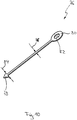
- the wall mounting portion 14 as shown in FIGS. 1 to 4 has only one mounting hole 18, the facade mounting portion 16 on the sheet metal portion 44 a keyhole-like mounting opening 74 for a in FIG. 10 shown tie rods 76.
- the tie rod 76 has a connecting portion 78 which can be connected to the facade fastening portion 16 and a mounting portion 80 facing away from the connecting portion 78 for mounting on a building wall.
- the tie rod 76 is formed so that it can be arranged centrally above the facade fastening portion 16 on a building wall, so that acting on the facade fastening portion 16 bending moments to the building wall can be derived.
- the tie rod 76 for mounting on a building wall has a loop-like mounting portion 80 with a bore 82.
- the connecting portion 78 of the tie rod 76 is arrow-shaped such that it can be secured by pulling in the mounting hole 80 against pulling out.
- the tie rod at the connecting portion has a width 84 which is greater than a width 86 of the mounting opening 74 of the facade fastening portion 16.
- the tie rod 76 at its narrowest point has a width 88 which is slightly smaller than the width 86 of the facade fastening portion 16 ,
- a simple and tool-free attachment of the tie rod 76 on the facade mounting portion 16 are made possible.
- tie rod 76 is screwed above the screw of the mounting hole 18 to a wall.
- FIGS. 6 to 9 a second embodiment of a console 100 according to the invention is shown.
- the console 10 according to the FIGS. 1 to 5 corresponding elements are with the corresponding ones Reference number marked.
- the console 100 is in FIG. 6 in a first oblique view and in FIG. 7 in a second oblique view looking in the direction of the arrow 102 in FIG FIG. 6 shown.
- the console 100 is formed as a one-piece bent metal part made of stainless steel. This is advantageous over the console 10 according to the FIGS. 1 to 5 because it is cheaper to produce.
- the bracket 100 also has a wall attachment portion 14 and a facade attachment portion 16, the wall attachment portion 14 and the facade attachment portion 16 being integral.
- the bracket 100 is formed in the region of the contact surface 20 as a double-layered sheet metal, wherein the wall fastening portion 14 has an upper sheet metal portion 104 and a lower sheet metal portion 106 which in FIG. 8 are clearly visible.
- the upper sheet metal section 104 forms the contact surface 20.
- the development 108 is produced by laser cutting from a metal sheet, wherein all slots, recesses and attachment points are already introduced by laser cutting in the sheet.
- a bending of the first sheet metal section 44 relative to the second sheet metal section 46 takes place about a bending line 110 until the sheet metal sections 44, 46 are arranged at an angle of approximately 90 ° to one another.
- the lower sheet metal section 106 is bent about a bending line 112 until the lower sheet metal section 106 is arranged at an angle of approximately 90 ° to the second sheet metal section 46.
- Sheet metal portion 104 around a bending line 114 to the upper sheet metal portion 104 is disposed at an angle of about 90 ° to the first sheet portion 44 and covers the lower sheet metal portion 106 so that the mounting holes 18 overlap.
- the assembly of the console 100 according to the FIGS. 5 to 9 takes place analogously to the mounting of the console 10 according to the FIGS. 1 to 5 ,
Landscapes
- Engineering & Computer Science (AREA)
- Architecture (AREA)
- Civil Engineering (AREA)
- Structural Engineering (AREA)
- Physics & Mathematics (AREA)
- Electromagnetism (AREA)
- Finishing Walls (AREA)
- Load-Bearing And Curtain Walls (AREA)
- Joining Of Building Structures In Genera (AREA)
Description
- Die Erfindung betrifft eine Wandkonsole zur Befestigung von Fassadenelementen, insbesondere zur Befestigung von Wand- oder Deckenverkleidungen von insbesondere vorgehängten, hinterlüfteten Fassaden, mit einem Wandbefestigungsabschnitt, der zur Montage der Konsole an einer Gebäudewand ausgebildet ist, und mit einem Fassadenbefestigungsabschnitt, der zur Montage von Trag- und Montageprofilen ausbildet ist.
- Derartige Konsolen sind aus dem Stand der Technik vielfach bekannt. So zeigt beispielsweise die
EP 0 901 549 B1 eine Wandstütze für Fassadenunterkonstruktionen mit einem Befestigungsschenkel zur Montage der Wandstütze an einer tragenden Wand und einem sich dazu senkrecht erstreckenden Tragschenkel, wobei der Tragschenkel einen Schenkellappen zum Einklemmen eines Tragprofils aufweist. Aus derEP 2 354 368 A2 , derDE 10 2009 030 635 A1 , derDE 30 05 315 A1 und derFR 2 924 138 A1 - Nachteilig an einer solchen aus dem Stand der Technik bekannten Konsole ist, dass diese Konsolen meist als Aluminium-Strangpressteile hergestellt sind. Derartige Aluminium-Strangpressteile weisen einerseits eine hohe Wärmeleitfähigkeit auf, so dass eine Isolation eines Gebäudes nicht ohne weiteres gewährleistet werden kann, da die Aluminium-Strangpressteile als Wärmebrücke wirken.
- Andererseits sind Aluminium-Strangpressteile in ihrer Länge begrenzt und erzeugen hohe Kosten bei der Matrizenfertigung.
- Ferner weisen die aus dem Stand der Technik bekannten Konsolen wie beispielsweise die aus der
EP 0 901 549 B1 bekannte Wandstütze lediglich eine Möglichkeit horizontale oder vertikale zur Befestigung von Trag- oder Montageprofilen auf, an denen wiederum Fassadenelemente anbringbar sind. - Die Erfindung stellt sich daher die Aufgabe, eine Konsole bereitzustellen, mit welcher eine Befestigung von Trag- oder Montageprofilen an einer Gebäudewand auf einfache und sichere Art und Weise ermöglicht wird.
- Diese Aufgabe wird durch eine Konsole mit den Merkmalen des Anspruchs 1 gelöst. Eine derartige Konsole zeichnet sich dadurch aus, dass der Fassadenbefestigungsabschnitt einen ersten Anschlussabschnitt zur horizontalen Montage von Trag- oder Montageprofilen und einen zweiten Anschlussabschnitt zur vertikalen Montage von Trag- oder Montageprofilen aufweist, der senkrecht zum ersten Anschlussabschnitt angeordnet ist. Somit kann mit einer derartigen Konsole eine Montage von Trag- oder Montageprofilen zur Anbringung von Fassadenelementen sowohl horizontal am ersten Anschlussabschnitt als auch vertikal am zweiten Anschlussabschnitt ermöglicht werden. Ein Vorhalten verschiedener Konsolen jeweils für die horizontale und vertikale Montage kann somit vermieden werden.
- Besonders bevorzugt ist es dabei, wenn der erste Anschlussabschnitt in einer Ebene angeordnet ist, welche senkrecht zur einer Ebene angeordnet ist, in welcher der zweite Anschlussabschnitt angeordnet ist. Der Wandbefestigungsabschnitt weist vorzugsweise wenigstens eine, vorzugsweise zwei oder mehrere übereinander angeordnete Montagebohrungen auf, mittels derer der Wandbefestigungsabschnitt an einer Gebäudewand befestigt, beispielsweise verschraubt werden kann.
- Eine erste vorteilhafte Weiterbildung der Konsole sieht vor, dass der erste und zweite Anschlussabschnitt senkrecht zu einer Anlagefläche des Wandbefestigungsabschnitts angeordnet sind, die zur Montage an einer Gebäudewand ausgebildet ist. Dabei ist die Anlagefläche vorzugsweise in einer Ebene angeordnet, die senkrecht zu den beiden Ebenen angeordnet ist, in denen die Anschlussabschnitte jeweils angeordnet sind.
- Erfindungsgemäß ist ferner vorgesehen, dass die Anschlussabschnitte an einem freien Ende der Konsole angeordnet sind, das dem Wandbefestigungsabschnitt abgewandt ist. Besonders bevorzugt ist es dabei, wenn der Wandbefestigungsabschnitt und der Fassadenbefestigungsabschnitt einstückig trägerartig miteinander verbunden sind.
- Erfindungsgemäß ist darüber hinaus vorgesehen, dass die Anschlussabschnitte am freien Ende jeweils wenigstens einen Fixpunkt und einen Gleitpunkt zur Montage von Trag- oder Montageprofilen aufweisen. Als Fixpunkt ist eine kreisrunde Bohrung vorgesehen, wobei mittels eines derartigen Fixpunkts die Hauptlast, nämlich das an einer Vielzahl von Konsolen angeordnete Fassadengewicht getragen werden kann. Als Gleitpunkt ist ein Langloch vorgesehen, wobei mittels eines derartigen Gleitpunkts vom Wind hervorgerufene, an einer Gebäudefassade angreifende Sog- und Druckkräfte abgeleitet werden können. Bei Vorsehen wenigstens eines Fixpunkts und wenigstens eines Gleitpunkts hat es sich als besonders vorteilhaft erwiesen, wenn abwechselnd jeweils mehrere Fix- und Gleitpunkte vorgesehen sind.
- Eine weitere vorteilhafte Weiterbildung der Konsole sieht vor, dass die Konsole als Blechbiegeteil ausgebildet ist. Dabei kann einerseits vorgesehen sein, dass das Blech in einem ersten Schritt mittels eines Lasers geschnitten oder gestanzt wird und dann in einem zweiten Schritt eine ausgeschnittene Abwicklung der Konsole gefaltet wird.
- Durch Wahl der Blechdicke kann ferner eine Anpassung an zu haltende Lasten ermöglicht werden, wobei die Blechdicke vorzugsweise in einem Bereich zwischen 1 und 4mm gewählt ist. Die Wahl der Blechdicke erfolgt dabei vorzugsweise jeweils angepasst an die statische Anforderung. Als besonders vorteilhaft hat es sich ferner erwiesen, die Konsole aus vorzugsweise Edelstahl herzustellen, da Edelstahl im Gegensatz zu Aluminium eine geringere Wärmeleitfähigkeit aufweist und sich somit positiv auf eine Wärmeentkopplung der Fassade von einer Gebäudewand erweist. Es ist jedoch auch denkbar, die Konsole aus anderen Materialien wie beispielsweise Aluminium oder andere Stahllegierungen herzustellen.
- Besonders bevorzugt ist es ferner, wenn die Konsole im Bereich der Anlagefläche des Wandbefestigungsabschnitts wenigstens eine, vorzugsweise zwei klauenartige Blechlaschen aufweist. Vorteilhafterweise ist die Blechlasche in einer Ebene angeordnet, die parallel zur Ebene der Anlagefläche angeordnet ist. Dabei ist es auch denkbar, dass die Blechlasche in der Ebene der Anlagefläche angeordnet ist.
- Zur thermischen Entkopplung von Gebäudewand und Fassade hat es sich ferner als besonders vorteilhaft erwiesen, wenn ein Thermoelement zur Wärmeisolierung gegenüber einer Gebäudewand vorgesehen ist, das einen geringeren Wärmeübergangskoeffizienten als der Wandbefestigungsabschnitt aufweist und das derart ausgebildet ist, dass es auf die Anlagefläche mittels der klauenartigen Blechlaschen aufklipsbar ist. Besonders bevorzugt ist es, wenn das Thermoelement aus einem Kunststoff, beispielsweise aus Polyamid hergestellt ist.
- In einer weiteren vorteilhaften Ausgestaltung der Konsole ist vorgesehen, dass der Fassadenbefestigungsabschnitt einen ersten Blechabschnitt, der in der Ebene des ersten Anlageabschnitts angeordnet ist, und einen zweiten Blechabschnitt aufweist, der in der Ebene des zweiten Anlageabschnitts angeordnet ist, wobei der erste Blechabschnitt und der zweite Blechabschnitt einstückig verbunden sind. Dabei kann das der erste Blechabschnitt folglich senkrecht zum zweiten Blechabschnitt angeordnet sein, wobei das Blech vorzugsweise in einem Winkel von etwa 90° gebogen ist.
- Ferner hat es sich als besonders vorteilhaft erwiesen, wenn der zweite Blechabschnitt eine maximale Breite aufweist, die größer ist als eine maximale Breite des ersten Blechabschnitts, und wenn der zweite Blechabschnitt eine minimale Breite aufweist, die größer ist als eine minimale Breite des ersten Blechabschnitts. Da der erste Blechabschnitt in einer Ebene mit dem ersten Anlageabschnitt angeordnet ist, der zur Montage von horizontal angeordneten Trag- oder Montageprofilen vorgesehen ist, und der zweite Blechabschnitt in einer Ebene mit dem zweiten Anlageabschnitt angeordnet ist, der zur Montage von vertikal angeordneten Trag- oder Montageprofilen angeordnet ist, kann durch die stets größere Breite des zweiten Blechabschnitts ein größeres Widerstandsmoment gegen Biegung bereitgestellt werden.
- Ferner kann insbesondere bei einer einstückigen Ausbildung der Konsole vorgesehen sein, dass die Konsole im Bereich der Anlagefläche des Wandbefestigungsabschnitts als doppellagiges Blech ausgebildet ist.
- Weiterhin ist es besonders vorteilhaft, wenn der Wandbefestigungsabschnitt einen oberen Blechabschnitt und einen unteren Blechabschnitt aufweist, wobei der obere Blechabschnitt die Anlagefläche bildet. Besonders vorteilhaft ist es dabei, wenn die klauenartige Blechlasche im unteren Blechabschnitt d.h. in dem im Montagezustand der Gebäudewand abgewandten Blechabschnitt angeordnet ist, so dass der obere Blechabschnitt zusätzlich mittels der Blechlasche abgestützt werden kann.
- In einer besonders vorteilhaften Ausgestaltung der Konsole ist vorgesehen, dass der erste Blechabschnitt des Fassadenbefestigungsabschnitts mit dem oberen Blechabschnitt einstückig verbunden ist und dass der zweite Blechabschnitt des Fassadenbefestigungsabschnitts mit dem unteren Blechabschnitt einstückig verbunden ist. Vorteilhafterweise sind die Blechabschnitte dabei in einem Winkel von 90° miteinander beispielsweise durch Biegen miteinander verbunden.
- Besonders bevorzugt ist es ferner, wenn die Anlagefläche eine Höhe aufweist, die größer ist als eine maximale Breite der Anlagefläche. Dabei entspricht die Höhe der Anlagefläche vorzugsweise der maximalen Breite des zweiten Blechabschnitts. Wenn die Anlagefläche eine größere Höhe als Breite aufweist, kann entsprechend der Ausgestaltung der Blechabschnitte des Fassadenbefestigungsabschnitts ein großes Widerstandsmoment gegen Biegung erreicht werden. Mit einer mehrteiligen, insbesondere zweiteiligen Ausbildung der Konsole kann erreicht werden, dass eine Fassadenbekleidung welche mittels der Trag- oder Montageprofile mit der zweiteiligen Konsole verbunden ist, sich zwangsfrei in eine vorher festgelegte Richtung ausdehnen kann. Somit können sichtbare Verschiebungen an der Fassadenoberfläche vermieden werden.
- Vorteilhafterweise ist die Konsole einstückig ausgebildet. Dabei ist vorteilhafterweise vorgesehen, dass der Fassadenbefestigungsabschnitt und der Wandbefestigungsabschnitt einstückig ausgebildet sind. Dies ist von Vorteil, da eine einstückige Konsole besonders kostengünstig herstellbar ist.
- Zur Herstellung einer günstigen und korrosionsbeständigen Konsole ist es besonders bevorzugt, wenn die Konsole aus Blech, insbesondere aus Edelstahl hergestellt ist.
- Um Biegemomente an eine Gebäudewand abzuleiten ist es ferner besonders vorteilhaft, wenn die Konsole einen Zuganker aufweist, wobei der Zuganker einen mit dem Fassadenbefestigungsabschnitt verbindbaren Verbindungsabschnitt und einen dem Verbindungsabschnitt abgewandten Montageabschnitt zur Montage an einer Wand aufweist. Vorteilhafterweise ist der Zuganker so ausgebildet, dass er mittig oberhalb des Fassadenbefestigungsabschnitts an einer Gebäudewand angeordnet werden kann, so dass auf den Fassadenbefestigungsabschnitt wirkende Biegemomente zur Gebäudewand hin abgeleitet werden können. Besonders bevorzugt ist es dabei, wenn der Zuganker zur Montage an einer Gebäudewand einen ösenartigen Montageabschnitt aufweist. Das Vorsehen eines Zugankers hat sich als besonders vorteilhaft erwiesen, wenn am Wandbefestigungsabschnitt lediglich eine Montagebohrung vorgesehen ist.
- Vorteilhafterweise weist der Fassadenbefestigungsabschnitt eine Montageöffnung für den Zuganker auf. Dabei ist es besonders vorteilhaft, wenn die Montageöffnung schlüssellochartig ausgebildet ist und wenn der Verbindungsabschnitt des Zugankers pfeilförmig derart ausgebildet ist, dass er durch Verdrehen in der Montageöffnung gegen Herausziehen gesichert werden kann. Somit kann eine einfache und werkzeuglose Befestigung des Zugankers am Fassadenbefestigungsabschnitt ermöglicht werden.
- Weitere Einzelheiten und vorteilhafte Weiterbildungen der Erfindung ergeben sich aus der nachfolgenden Beschreibung, anhand derer verschiedene Ausführungsformen der Erfindung näher beschrieben und erläutert sind.
- Es zeigen:
-
Figur 1 eine erste Ausführungsform einer erfindungsgemäßen Konsole in Schrägansicht; -
Figur 2 die Konsole gemäßFigur 2 in einer weiteren Schrägansicht; -
Figur 3 einen Wandbefestigungsabschnitt der Konsole gemäßFiguren 1 und2 in einer Schrägansicht; -
Figur 4 den Wandbefestigungsabschnitt gemäßFigur 3 in einer weiteren Schrägansicht; -
Figur 5 einen Fassadenbefestigungsabschnitt der Konsole gemäßFiguren 1 und2 in einer Schrägansicht; -
Figur 6 den Fassadenbefestigungsabschnitt gemäßFigur 5 in einer weiteren Schrägansicht; -
Figur 7 eine zweite Ausführungsform einer erfindungsgemäßen Konsole in Schrägansicht; -
Figur 8 die Konsole gemäßFigur 7 in einer weiteren Schrägansicht mit einem daran angeordneten Thermoelement; -
Figur 9 eine Abwicklung der Konsole gemäß derFiguren 7 und8 ; und -
Figur 10 einen Zuganker für eine erfindungsgemäße Konsole in einer Schrägansicht. - In den
Figuren 1 bis 5 ist eine erste Ausführungsform einer erfindungsgemäßen Konsole 10 gezeigt. Die Konsole 10 ist dabei inFigur 1 in einer ersten Schrägansicht und inFigur 2 in einer zweiten Schrägansicht bei Blick in Richtung des Pfeils 12 inFigur 1 dargestellt. - Wie in
Figur 1 undFigur 2 deutlich zu erkennen ist, ist die Konsole 10 als mehrteiliges Blechbiegeteil aus Edelstahl ausgebildet. Die Konsole 10 weist einen Wandbefestigungsabschnitt 14 und einen Fassadenbefestigungsabschnitt 16 auf. - Der Wandbefestigungsabschnitt 14 ist zur Montage der Konsole 10 an einer nicht dargestellten Gebäudewand mittels der Montagebohrung 18 ausgebildet und in den
Figuren 3 und4 in Alleindarstellung in zwei verschiedenen Schrägansichten gezeigt. Die Montagebohrung 18 ist in einer Anlagefläche 20 des Wandbefestigungsabschnitts 14 angeordnet, die zur Montage an einer Gebäudewand ausgebildet ist. - Wie in den
Figuren 3 und4 ferner deutlich zu erkennen ist, ist der Wandbefestigungsabschnitt 14 als Blechwinkel ausgebildet, wobei ein Schenkel 22 in einem Winkel von etwa 90° zur Anlagefläche 20 angeordnet ist. Der Wandbefestigungsabschnitt 14 weist im Bereich der Anlagefläche zwei klauenartige Blechlaschen 24 auf, die in einer Ebene mit der Anlagefläche 20 angeordnet sind und die Anlagefläche 20 somit verbreitern. Ferner sind die Blechlaschen 24 dazu ausgelegt, um ein in denFiguren 1 und2 gezeigtes Thermoelement 26 aus Polyamid oder einem Kunststoff mit einem niedrigen Wärmeübergangskoeffizienten auf die Blechlaschen 24 bzw. auf den Wandbefestigungsabschnitt 14 aufzuklipsen, so dass eine Wärmeentkopplung des Wandbefestigungsabschnitts 14 von der nicht dargestellten Gebäudewand erfolgen kann. Auf der der Anlagefläche 20 abgewandten Seite weist der Wandbefestigungsabschnitt 14 eine Mittenmarkierung 27 zur Ausrichtung der Konsole 10 an einer Wand auf. - In den Schenkel 22 ist an einer Oberseite 28 eine Aussparung 30 eingebracht, die so ausgebildet ist, dass der Schenkel 22 an der Oberseite 28 zwei Vorsprünge 32, 34 bildet. Der Vorsprung 34 weist an der Oberseite 28 auf seinem der Vorsprung 32 zugewandten Ende eine Nase 36 auf, die sich in Richtung des Vorsprungs 32 erstreckt.
- Der Fassadenbefestigungsabschnitt 16 ist in Alleindarstellung in
Figur 5 gezeigt. Der Fassadenbefestigungsabschnitt 16 weist an seinem freien Ende 38 einen ersten Anschlussabschnitt 40 zur horizontalen Montage von nicht dargestellten Trag- oder Montageprofilen und einen zweiten Anschlussabschnitt 42 zur vertikalen Montage von Trag- oder Montageprofilen auf, wobei der zweite Anschlussabschnitt 42 senkrecht zum ersten Anschlussabschnitt 40 angeordnet ist. - Ferner weist der Fassadenbefestigungsabschnitt 16 einen ersten Blechabschnitt 44, der in einer Ebene des ersten Anlageabschnitts 40 angeordnet ist, und einen zweiten Blechabschnitt 46, der in einer Ebene des zweiten Anlageabschnitts 42 angeordnet ist, auf, wobei der erste Blechabschnitt 44 und der zweite Blechabschnitt 46 einstückig miteinander verbunden sind. Der erste Blechabschnitt 44 und der zweite Blechabschnitt 46 sind durch Biegen in einem Winkel von etwa 90° zueinander angeordnet.
- Im Bereich des freien Endes 38 ist zwischen dem ersten Blechabschnitt 44 und dem zweiten Blechabschnitt 46 ein zum freien Ende 38 hin offener Schlitz 48 vorgesehen, der bei einer Montage von Trag- oder Montageprofilen an den Anschlussabschnitten 40, 42 zur Durchführung von Abschnitten eines jeweiligen Trag- oder Montageprofils vorgesehen ist. Die Anschlussabschnitte 40, 42 weisen ferner jeweils wenigstens einen als kreisrunde Bohrung ausgebildeten Fixpunkt 50 und wenigstens einen als Langloch ausgebildeten Gleitpunkt 52 auf.
- Mittels eines derartigen Fixpunkts 50 kann die Hauptlast, nämlich das an einer Vielzahl von Konsolen 10 angeordnete Fassadengewicht getragen werden kann, wobei mittels eines derartigen Gleitpunkts 52 vom Wind hervorgerufene, an einer Gebäudefassade angreifende Sog- und Druckkräfte abgeleitet werden können.
- Auf der dem freien Ende 38 abgewandten Seite weist der Fassadenbefestigungsabschnitt 16 zwischen dem ersten Blechabschnitt 44 und dem zweiten Blechabschnitt 46 ebenfalls einen offenen Schlitz 54 auf. In einem Abstand 56 vom Schlitz 54, der geringfügig kleiner als eine Breite 58 der Aussparung 30 des Wandbefestigungsabschnitts 14 ist, ist ein weiterer Schlitz 60 zwischen dem ersten Blechabschnitt 44 und dem zweiten Blechabschnitt 46 angeordnet.
- Der Schlitz 60 weist eine Länge 62 auf, die geringfügig größer als eine Breite 64 des Vorsprungs 32 des Wandbefestigungsabschnitts 14 gewählt ist so dass der Fassadenbefestigungsabschnitt 16 wie in den
Figuren 1 und2 gezeigt mit dem Wandbefestigungsabschnitt 14 verbunden werden kann, wobei der Vorsprung 32 in den Schlitz 60 eingeführt wird und die Nase 36 ein Herausgleiten des Fassadenbefestigungsabschnitts 16 verhindert. - Zur Bereitstellung eines möglichst großen Widerstandsmoments gegen Biegung weist der erste Blechabschnitt 44 eine Breite 66 auf, wobei der zweite Blechabschnitt 46 eine Breite 68 aufweist. Die Breite 68 und die Breite 66 sind jeweils derart gewählt, dass die maximale Breite 68 entlang der Längserstreckung des Fassadenbefestigungsabschnitts 16 stets größer ist als die jeweilige maximale Breite 66 und dass die minimale Breite 68 entlang der Längserstreckung des Fassadenbefestigungsabschnitts 16 ebenfalls stets größer ist als die jeweilige minimale Breite 66.
- Ebenfalls zur Bereitstellung eines möglichst großen Widerstandsmoments gegen Biegung weist die Anlagefläche 20 eine Höhe 70 auf, die größer ist als eine maximale Breite 72 der Anlagefläche 20. Dies ist in
Figur 4 deutlich zu erkennen. - Für den Fall, dass der Wandbefestigungsabschnitt 14 wie in den
Figuren 1 bis 4 lediglich eine Montagebohrung 18 aufweist, weist der Fassadenbefestigungsabschnitt 16 am Blechabschnitt 44 eine schlüssellochartige Montageöffnung 74 für einen inFigur 10 dargestellten Zuganker 76 auf. - Der Zuganker 76 weist einen mit dem Fassadenbefestigungsabschnitt 16 verbindbaren Verbindungsabschnitt 78 und einen dem Verbindungsabschnitt 78 abgewandten Montageabschnitt 80 zur Montage an einer Gebäudewand auf. Dabei ist der Zuganker 76 so ausgebildet, dass er mittig oberhalb des Fassadenbefestigungsabschnitts 16 an einer Gebäudewand angeordnet werden kann, so dass auf den Fassadenbefestigungsabschnitt 16 wirkende Biegemomente zur Gebäudewand hin abgeleitet werden können.
- Besonders bevorzugt ist es dabei, wenn der Zuganker 76 zur Montage an einer Gebäudewand einen ösenartigen Montageabschnitt 80 mit einer Bohrung 82 aufweist. Der Verbindungsabschnitt 78 des Zugankers 76 ist pfeilförmig derart ausgebildet ist, dass er durch Verdrehen in der Montageöffnung 80 gegen Herausziehen gesichert werden kann. Hierzu weist der Zuganker am Verbindungsabschnitt eine Breite 84 auf, die größer ist als eine Breite 86 der Montageöffnung 74 des Fassadenbefestigungsabschnitts 16. Ferner weist der Zuganker 76 an seiner schmalsten Stelle eine Breite 88 auf, die geringfügig kleiner als die Breite 86 des Fassadenbefestigungsabschnitts 16 ist. Somit kann eine einfache und werkzeuglose Befestigung des Zugankers 76 am Fassadenbefestigungsabschnitt 16 ermöglicht werden.
- Zur Befestigung der Konsole 10 erfolgt zunächst eine Verschraubung mittels der Montagebohrung 18, wobei anschließend der in der Montageöffnung 74 angeordnete Zuganker 76 oberhalb der Verschraubung der Montagebohrung 18 an einer Wand verschraubt wird.
- In den
Figuren 6 bis 9 ist eine zweite Ausführungsform einer erfindungsgemäßen Konsole 100 gezeigt. Die der Konsole 10 gemäß denFiguren 1 bis 5 entsprechenden Elemente sind mit den entsprechenden Bezugszeichen gekennzeichnet. Die Konsole 100 ist dabei inFigur 6 in einer ersten Schrägansicht und inFigur 7 in einer zweiten Schrägansicht bei Blick in Richtung des Pfeils 102 inFigur 6 dargestellt. - Wie in
Figur 6 undFigur 7 deutlich zu erkennen ist, ist die Konsole 100 als einteiliges Blechbiegeteil aus Edelstahl ausgebildet. Dies ist von Vorteil gegenüber der Konsole 10 gemäß derFiguren 1 bis 5 , da sie billiger herstellbar ist. - Die Konsole 100 weist ebenfalls einen Wandbefestigungsabschnitt 14 und einen Fassadenbefestigungsabschnitt 16 auf, wobei der Wandbefestigungsabschnitt 14 und der Fassadenbefestigungsabschnitt 16 einstückig sind.
- Dabei ist die Konsole 100 im Bereich der Anlagefläche 20 als doppellagiges Blech ausgebildet, wobei der Wandbefestigungsabschnitt 14 einen oberen Blechabschnitt 104 und einen unteren Blechabschnitt 106 aufweist, die in
Figur 8 deutlich zu erkennen sind. Der obere Blechabschnitt 104 bildet dabei die Anlagefläche 20. - Aufgrund der einstückigen Ausbildung ist der erste Blechabschnitt 44 des Fassadenbefestigungsabschnitts 16 mit dem oberen Blechabschnitt 104 einstückig verbunden, wobei der zweite Blechabschnitt 46 mit dem unteren Blechabschnitt 106 einstückig verbunden ist. Dies ist auch in
Figur 9 deutlich zu erkennen, die eine Abwicklung 108 der Konsole 100 gemäß derFiguren 7 und8 zeigt. - Die Abwicklung 108 ist durch Laserschneiden aus einem Blech hergestellt, wobei alle Schlitze, Aussparungen und Befestigungspunkte bereits durch Laserschneiden in das Blech eingebracht sind.
- Zunächst erfolgt ein Verbiegen des ersten Blechabschnitts 44 gegenüber dem zweiten Blechabschnitt 46 um eine Biegelinie 110 bis die Blechabschnitte 44, 46 in einem Winkel von etwa 90° zueinander angeordnet sind.
- In einem zweiten Schritt erfolgt ein Verbiegen des unteren Blechabschnitts 106 um eine Biegelinie 112 bis der untere Blechabschnitt 106 in einem Winkel von etwa 90° zum zweiten Blechabschnitt 46 angeordnet ist.
- In einem dritten Schritt erfolgt schließlich ein Verbiegen des oberen Blechabschnitts 104 um eine Biegelinie 114 bis der obere Blechabschnitt 104 in einem Winkel von etwa 90° zum ersten Blechabschnitt 44 angeordnet ist und den unteren Blechabschnitt 106 so überdeckt, dass sich die Montagebohrungen 18 überlagern.
- Die Montage der Konsole 100 gemäß den
Figuren 5 bis 9 erfolgt analog zur Montage der Konsole 10 gemäß denFiguren 1 bis 5 .
Claims (15)
- Konsole (10, 100) zur Befestigung von Fassadenelementen von insbesondere vorgehängten, hinterlüfteten Fassaden, mit einem Wandbefestigungsabschnitt (14), der zur Montage der Konsole (10, 100) an einer Gebäudewand ausgebildet ist, und mit einem Fassadenbefestigungsabschnitt (16), der zur Montage von Trag- oder Montageprofilen ausbildet ist, dadurch gekennzeichnet, dass der Fassadenbefestigungsabschnitt (16) einen ersten Anschlussabschnitt (40) zur horizontalen Montage von Trag- oder Montageprofilen und einen zweiten Anschlussabschnitt (42) zur vertikalen Montage von Trag- oder Montageprofilen aufweist, der senkrecht zum ersten Anschlussabschnitt (40) angeordnet ist, wobei die Anschlussabschnitte (40, 42) an einem freien Ende (38) der Konsole (10, 100) angeordnet sind, das dem Wandbefestigungsabschnitt (14) abgewandt ist und wobei die Anschlussabschnitte (40, 42) am freien Ende (38) jeweils wenigstens einen Fixpunkt (50) in Form einer kreisrunden Bohrung und einen Gleitpunkt (52) in Form eines Langlochs zur Montage von Trag- oder Montageprofilen aufweisen.
- Konsole (10, 100) nach Anspruch 1, dadurch gekennzeichnet, dass der erste und zweite Anschlussabschnitt (40, 42) senkrecht zu einer Anlagefläche (20) des Wandbefestigungsabschnitts (14) angeordnet sind, die zur Montage an einer Gebäudewand ausgebildet ist.
- Konsole (10, 100) nach Anspruch 1 oder 2, dadurch gekennzeichnet, dass die Konsole (10, 100) als Blechbiegeteil ausgebildet ist.
- Konsole (10, 100) nach wenigstens einem der vorhergehenden Ansprüche, dadurch gekennzeichnet, dass die Konsole (10, 100) im Bereich der Anlagefläche (20) des Wandbefestigungsabschnitts (14) wenigstens eine, vorzugsweise zwei klauenartige Blechlaschen (24) aufweist.
- Konsole (10, 100) nach Anspruch 4, dadurch gekennzeichnet, dass ein Thermoelement (26) zur Wärmeisolierung gegenüber einer Gebäudewand vorgesehen ist, das einen geringeren Wärmeübergangskoeffizienten als der Wandbefestigungsabschnitt (14) aufweist und das derart ausgebildet ist, dass es auf die Anlagefläche (20) mittels der klauenartigen Blechlaschen (24) aufklipsbar ist.
- Konsole (10, 100) nach wenigstens einem der vorhergehenden Ansprüche, dadurch gekennzeichnet, dass der Fassadenbefestigungsabschnitt (16) einen ersten Blechabschnitt (44), der in der Ebene des ersten Anlageabschnitts (40) angeordnet ist, und einen zweiten Blechabschnitt (46) aufweist, der in der Ebene des zweiten Anlageabschnitts (42) angeordnet ist, wobei der erste Blechabschnitt (44) und der zweite Blechabschnitt (46) einstückig verbunden sind.
- Konsole (10, 100) nach Anspruch 6, dadurch gekennzeichnet, dass der zweite Blechabschnitt (46) eine maximale Breite (68) aufweist, die größer ist als eine maximale Breite (66) des ersten Blechabschnitts (44), und dass der zweite Blechabschnitt (46) eine minimale Breite (68) aufweist, die größer ist als eine minimale Breite (66) des ersten Blechabschnitts (44).
- Konsole (100) nach wenigstens einem der vorhergehenden Ansprüche, dadurch gekennzeichnet, dass die Konsole (10, 100) im Bereich der Anlagefläche (20) des Wandbefestigungsabschnitts (14) als doppellagiges Blech ausgebildet ist.
- Konsole (100) nach wenigstens einem der vorhergehenden Ansprüche, dadurch gekennzeichnet, dass der Wandbefestigungsabschnitt (14) einen oberen Blechabschnitt (104) und einen unteren Blechabschnitt (106) aufweist, wobei der obere Blechabschnitt (104) die Anlagefläche (20) bildet.
- Konsole (100) nach Anspruch 6 und 9, dadurch gekennzeichnet, dass der erste Blechabschnitt (44) des Fassadenbefestigungsabschnitts (16) mit dem oberen Blechabschnitt (104) einstückig verbunden ist und dass der zweite Blechabschnitt (46) des Fassadenbefestigungsabschnitts (16) mit dem unteren Blechabschnitt (106) einstückig verbunden ist.
- Konsole (10, 100) nach wenigstens einem der vorhergehenden Ansprüche, dadurch gekennzeichnet, dass die Anlagefläche (20) eine Höhe (70) aufweist, die größer ist als eine maximale Breite (72) der Anlagefläche (20).
- Konsole (100) nach wenigstens einem der vorhergehenden Ansprüche, dadurch gekennzeichnet, dass die Konsole (100) einstückig ausgebildet ist.
- Konsole (10,100) nach wenigstens einem der vorhergehenden Ansprüche, dadurch gekennzeichnet, dass die Konsole (10, 100) aus Blech, insbesondere aus Edelstahl hergestellt ist.
- Konsole (10, 100) nach wenigstens einem der vorhergehenden Ansprüche, dadurch gekennzeichnet, dass die Konsole (10, 100) einen Zuganker (76) aufweist, wobei der Zuganker (76) einen mit dem Fassadenbefestigungsabschnitt (16) verbindbaren Verbindungsabschnitt (78) und einen dem Verbindungsabschnitt (78) abgewandten Montageabschnitt (80) zur Montage an einer Wand aufweist.
- Konsole (10, 100) nach Anspruch 14, dadurch gekennzeichnet, dass der Fassadenbefestigungsabschnitt (16) eine Montageöffnung (74) für den Zuganker (76) aufweist.
Priority Applications (6)
| Application Number | Priority Date | Filing Date | Title |
|---|---|---|---|
| HUE15716774A HUE046629T2 (hu) | 2015-04-14 | 2015-04-14 | Konzol homlokzati elemek rögzítésére |
| SI201530935T SI3283706T1 (sl) | 2015-04-14 | 2015-04-14 | Podpora za pritrditev fasadnih elementov |
| PT157167743T PT3283706T (pt) | 2015-04-14 | 2015-04-14 | Consola para a fixação de elementos de fachada |
| RS20191538A RS59645B1 (sr) | 2015-04-14 | 2015-04-14 | Nosač za pričvršćivanje fasadnih elemenata |
| PL15716774T PL3283706T3 (pl) | 2015-04-14 | 2015-04-14 | Konsola do mocowania elementów fasad |
| HRP20191891TT HRP20191891T1 (hr) | 2015-04-14 | 2015-04-14 | Konzola za pričvršćivanje elemenata pročelja |
Applications Claiming Priority (1)
| Application Number | Priority Date | Filing Date | Title |
|---|---|---|---|
| PCT/EP2015/058026 WO2016165741A1 (de) | 2015-04-14 | 2015-04-14 | Konsole zur befestigung von fassadenelementen |
Publications (2)
| Publication Number | Publication Date |
|---|---|
| EP3283706A1 EP3283706A1 (de) | 2018-02-21 |
| EP3283706B1 true EP3283706B1 (de) | 2019-09-18 |
Family
ID=52875680
Family Applications (1)
| Application Number | Title | Priority Date | Filing Date |
|---|---|---|---|
| EP15716774.3A Active EP3283706B1 (de) | 2015-04-14 | 2015-04-14 | Konsole zur befestigung von fassadenelementen |
Country Status (20)
| Country | Link |
|---|---|
| US (1) | US10273681B2 (de) |
| EP (1) | EP3283706B1 (de) |
| CN (1) | CN107429517B (de) |
| AU (1) | AU2015391344B2 (de) |
| BR (1) | BR112017021578B1 (de) |
| CY (1) | CY1122395T1 (de) |
| DK (1) | DK3283706T3 (de) |
| ES (1) | ES2750584T3 (de) |
| HR (1) | HRP20191891T1 (de) |
| HU (1) | HUE046629T2 (de) |
| LT (1) | LT3283706T (de) |
| MX (1) | MX378228B (de) |
| PL (1) | PL3283706T3 (de) |
| PT (1) | PT3283706T (de) |
| RS (1) | RS59645B1 (de) |
| RU (1) | RU2689105C2 (de) |
| SA (1) | SA517390099B1 (de) |
| SG (1) | SG11201708254RA (de) |
| SI (1) | SI3283706T1 (de) |
| WO (1) | WO2016165741A1 (de) |
Families Citing this family (7)
| Publication number | Priority date | Publication date | Assignee | Title |
|---|---|---|---|---|
| PL3239431T5 (pl) * | 2016-04-26 | 2025-11-03 | Leviat GmbH | Podpora kotwiąca do zamocowania oblicówki na ścianie nośnej |
| CA2996509A1 (en) * | 2016-06-10 | 2017-12-14 | Dirtt Environmental Solutions Inc. | Angled wall connector bracket for a wall |
| DE102017101509A1 (de) | 2017-01-26 | 2018-07-26 | Ejot Baubefestigungen Gmbh | Konsole zur Befestigung von Fassadenelementen |
| DE102017129031A1 (de) * | 2017-12-06 | 2019-06-06 | Truma Gerätetechnik GmbH & Co. KG | Heizmodul für eine Heizanlage eines bewohnbaren Fahrzeugs |
| JP7386618B2 (ja) | 2018-05-09 | 2023-11-27 | ブリガム・ヤング・ユニバーシティ | 摩擦ビット接合するシステム及び方法 |
| DE102021102504B3 (de) * | 2021-02-03 | 2022-07-07 | Ulrich Wagner | Wandhalter für eine vorgehängte hinterlüftete Fassade und vorgehängte hinterlüftete Fassade |
| US11814848B2 (en) * | 2021-10-14 | 2023-11-14 | Flynn Canada Ltd. | Mounting clip assembly providing thermal barrier |
Family Cites Families (18)
| Publication number | Priority date | Publication date | Assignee | Title |
|---|---|---|---|---|
| JPS5423775Y2 (de) * | 1974-11-27 | 1979-08-14 | ||
| DE3005315C2 (de) * | 1980-02-13 | 1985-07-25 | Peter Dipl.-Ing. 3303 Vechelde Wagner | Unterkonstruktion für eine Bauwerksbekleidung |
| AT410457B (de) * | 1999-07-26 | 2003-05-26 | Wiesner Hager Baugruppe Gmbh | Vorrichtung zum befestigen von hinterlüfteten fassadenplatten |
| CN1339643A (zh) * | 2000-08-21 | 2002-03-13 | 王广武 | 托架缝隙支撑幕墙 |
| DE202007009780U1 (de) * | 2007-07-11 | 2007-10-18 | Schröter, Bernd | Befestigungskonsole für Fassadenelemente an Gebäudewänden |
| FR2924138B1 (fr) * | 2007-11-28 | 2013-03-22 | Saint Gobain Isover | Systeme d'isolation de batiments par l'exterieur |
| DE102009030635B4 (de) * | 2009-06-25 | 2014-01-09 | Sto Ag | Haltewinkel für ein Fassadensystem |
| DE102010011168A1 (de) * | 2010-01-29 | 2011-08-04 | Lorenz Kunststofftechnik GmbH, 49134 | Befestigungsbügel für Wandisolierungen |
| RU2423588C1 (ru) * | 2010-03-30 | 2011-07-10 | Общество с ограниченной ответственностью "ТД ДИАТ" | Кронштейн навесной фасадной системы с воздушным зазором |
| PL68326Y1 (pl) * | 2011-05-25 | 2016-04-29 | Wido Profil Spółka Z Ograniczoną Odpowiedzialnością | Dekoracyjny panel akustyczny |
| DE102011102510A1 (de) * | 2011-05-26 | 2012-11-29 | Sfs Intec Holding Ag | System zum Befestigen einer Dämmfassade und dafür vorgesehener Befestiger |
| DE102012016025B4 (de) * | 2012-08-13 | 2020-02-27 | Nauth Sl Fassadentechnik Gmbh | Wandhalter zur Fixierung einer vorgehängten Fassade |
| RU126734U1 (ru) * | 2012-11-26 | 2013-04-10 | Общество с ограниченной ответственностью "ОЛМА" | Кронштейн для крепления профилей навесного фасада |
| CA2850715C (en) * | 2013-05-02 | 2017-09-05 | Donald George White | Thermal break wall systems and thermal adjustable clip |
| US9493941B2 (en) * | 2013-05-02 | 2016-11-15 | Donald George White | Thermal break wall systems and thermal adjustable clip |
| EP3075921A1 (de) * | 2015-04-03 | 2016-10-05 | Florim Ceramiche S.P.A.-Societa' Per Azioni Abbreviabile In "Florim S.P.A." | Belüftetes fassadensystem |
| PL238557B1 (pl) * | 2015-09-30 | 2021-09-06 | Wido Profil Spolka Z Ograniczona Odpowiedzialnoscia | Konsola montażowa |
| CA2942452C (en) * | 2016-01-20 | 2023-08-01 | Simpson Strong-Tie Company, Inc. | Slide clip connector |
-
2015
- 2015-04-14 HR HRP20191891TT patent/HRP20191891T1/hr unknown
- 2015-04-14 WO PCT/EP2015/058026 patent/WO2016165741A1/de not_active Ceased
- 2015-04-14 SG SG11201708254RA patent/SG11201708254RA/en unknown
- 2015-04-14 CN CN201580078756.0A patent/CN107429517B/zh active Active
- 2015-04-14 MX MX2017012819A patent/MX378228B/es unknown
- 2015-04-14 ES ES15716774T patent/ES2750584T3/es active Active
- 2015-04-14 BR BR112017021578-0A patent/BR112017021578B1/pt active IP Right Grant
- 2015-04-14 SI SI201530935T patent/SI3283706T1/sl unknown
- 2015-04-14 RU RU2017134885A patent/RU2689105C2/ru active
- 2015-04-14 RS RS20191538A patent/RS59645B1/sr unknown
- 2015-04-14 PL PL15716774T patent/PL3283706T3/pl unknown
- 2015-04-14 EP EP15716774.3A patent/EP3283706B1/de active Active
- 2015-04-14 PT PT157167743T patent/PT3283706T/pt unknown
- 2015-04-14 LT LT15716774T patent/LT3283706T/lt unknown
- 2015-04-14 AU AU2015391344A patent/AU2015391344B2/en active Active
- 2015-04-14 HU HUE15716774A patent/HUE046629T2/hu unknown
- 2015-04-14 DK DK15716774T patent/DK3283706T3/da active
- 2015-04-14 US US15/566,271 patent/US10273681B2/en active Active
-
2017
- 2017-10-04 SA SA517390099A patent/SA517390099B1/ar unknown
-
2019
- 2019-12-09 CY CY20191101291T patent/CY1122395T1/el unknown
Non-Patent Citations (1)
| Title |
|---|
| None * |
Also Published As
| Publication number | Publication date |
|---|---|
| CN107429517B (zh) | 2020-08-25 |
| DK3283706T3 (da) | 2019-12-09 |
| CN107429517A (zh) | 2017-12-01 |
| RU2017134885A (ru) | 2019-05-14 |
| CY1122395T1 (el) | 2021-01-27 |
| BR112017021578A2 (de) | 2018-09-25 |
| WO2016165741A1 (de) | 2016-10-20 |
| PL3283706T3 (pl) | 2020-02-28 |
| MX2017012819A (es) | 2018-04-11 |
| SI3283706T1 (sl) | 2019-11-29 |
| SA517390099B1 (ar) | 2021-05-25 |
| AU2015391344B2 (en) | 2018-11-29 |
| EP3283706A1 (de) | 2018-02-21 |
| US10273681B2 (en) | 2019-04-30 |
| MX378228B (es) | 2025-03-04 |
| RS59645B1 (sr) | 2020-01-31 |
| US20180119412A1 (en) | 2018-05-03 |
| RU2689105C2 (ru) | 2019-05-23 |
| HRP20191891T1 (hr) | 2020-01-10 |
| AU2015391344A1 (en) | 2017-10-19 |
| HUE046629T2 (hu) | 2020-03-30 |
| PT3283706T (pt) | 2019-12-23 |
| LT3283706T (lt) | 2019-11-11 |
| SG11201708254RA (en) | 2017-11-29 |
| BR112017021578B1 (pt) | 2022-02-01 |
| RU2017134885A3 (de) | 2019-05-14 |
| ES2750584T3 (es) | 2020-03-26 |
Similar Documents
| Publication | Publication Date | Title |
|---|---|---|
| WO2016165741A1 (de) | Konsole zur befestigung von fassadenelementen | |
| EP3574164B1 (de) | Konsole zur befestigung von fassadenelementen | |
| EP2565345A1 (de) | Montagewinkel mit Zugstrebe | |
| EP2940229B1 (de) | Vorrichtung zum Befestigen von Hohlelementen, beispielsweise an Fassaden | |
| EP2108756B1 (de) | Montageplatte zum Befestigen eines Montagewinkels für Fassadenelemente | |
| EP2404011B1 (de) | Verwendung einer vorrichtung zur befestigung von fassadenelementen | |
| EP1522668B1 (de) | Verbinder für Doppelfenster-Rahmenprofile | |
| DE202015009684U1 (de) | Konsole zur Befestigung von Fassadenelementen | |
| EP1983138B1 (de) | Gebäudeelement mit einem im Rahmen dichtend gehaltenen Ausfachungselement | |
| DE202009012001U1 (de) | Tragkonstruktion für Bauelemente, insbesondere für Photovoltaikpaneele | |
| EP3910125B1 (de) | Tragkonstruktion zur abhängung mindestens eines schallabsorbers von einer decke, system zur verbesserung der akustik in einem raum | |
| AT518069B1 (de) | Vorrichtung zur Befestigung von Fassadenteilen | |
| DE102005043934B4 (de) | Leitersprosse für Eigenbauleitern | |
| DE202020101933U1 (de) | Verbindungselement | |
| EP3322860B1 (de) | Klaue zur lasteinleitung in die wärmedämmung eines gebäudes | |
| EP4145651B1 (de) | Endseitig einseitig abgestützter ausleger für ein kabeltragsystem | |
| EP4621168B1 (de) | Wildschutz- oder weidezaunaufbausystem sowie aufbauverfahren damit | |
| DE102021120323B4 (de) | Endseitig einseitig abgestützter Ausleger für ein Kabeltragsystem | |
| DE202018100541U1 (de) | Verkleidungssystem zur Verkleidung einer Bauwerksfläche | |
| DE202024105271U1 (de) | Ausgleichsbauteil für mit Abstand montiertes Gebäudeteil | |
| EP0653540A2 (de) | Fensterbank | |
| DE20114555U1 (de) | Ankerwinkel | |
| WO2011144316A2 (de) | Anordnung zur befestigung von profilen | |
| DE102006014391B4 (de) | Klemmvorrichtung zur Befestigung an Fenster- und Türprofilen | |
| EP4417767A1 (de) | Geländertragprofil |
Legal Events
| Date | Code | Title | Description |
|---|---|---|---|
| STAA | Information on the status of an ep patent application or granted ep patent |
Free format text: STATUS: THE INTERNATIONAL PUBLICATION HAS BEEN MADE |
|
| PUAI | Public reference made under article 153(3) epc to a published international application that has entered the european phase |
Free format text: ORIGINAL CODE: 0009012 |
|
| STAA | Information on the status of an ep patent application or granted ep patent |
Free format text: STATUS: REQUEST FOR EXAMINATION WAS MADE |
|
| 17P | Request for examination filed |
Effective date: 20170929 |
|
| AK | Designated contracting states |
Kind code of ref document: A1 Designated state(s): AL AT BE BG CH CY CZ DE DK EE ES FI FR GB GR HR HU IE IS IT LI LT LU LV MC MK MT NL NO PL PT RO RS SE SI SK SM TR |
|
| AX | Request for extension of the european patent |
Extension state: BA ME |
|
| DAV | Request for validation of the european patent (deleted) | ||
| DAX | Request for extension of the european patent (deleted) | ||
| GRAP | Despatch of communication of intention to grant a patent |
Free format text: ORIGINAL CODE: EPIDOSNIGR1 |
|
| STAA | Information on the status of an ep patent application or granted ep patent |
Free format text: STATUS: GRANT OF PATENT IS INTENDED |
|
| RIC1 | Information provided on ipc code assigned before grant |
Ipc: E04B 1/41 20060101ALI20190320BHEP Ipc: E04B 1/38 20060101ALI20190320BHEP Ipc: E04F 13/08 20060101AFI20190320BHEP |
|
| INTG | Intention to grant announced |
Effective date: 20190412 |
|
| GRAS | Grant fee paid |
Free format text: ORIGINAL CODE: EPIDOSNIGR3 |
|
| GRAA | (expected) grant |
Free format text: ORIGINAL CODE: 0009210 |
|
| STAA | Information on the status of an ep patent application or granted ep patent |
Free format text: STATUS: THE PATENT HAS BEEN GRANTED |
|
| RAP1 | Party data changed (applicant data changed or rights of an application transferred) |
Owner name: EJOT AUSTRIA GMBH & CO KG |
|
| AK | Designated contracting states |
Kind code of ref document: B1 Designated state(s): AL AT BE BG CH CY CZ DE DK EE ES FI FR GB GR HR HU IE IS IT LI LT LU LV MC MK MT NL NO PL PT RO RS SE SI SK SM TR |
|
| REG | Reference to a national code |
Ref country code: GB Ref legal event code: FG4D Free format text: NOT ENGLISH |
|
| REG | Reference to a national code |
Ref country code: CH Ref legal event code: EP |
|
| REG | Reference to a national code |
Ref country code: DE Ref legal event code: R096 Ref document number: 502015010400 Country of ref document: DE |
|
| REG | Reference to a national code |
Ref country code: AT Ref legal event code: REF Ref document number: 1181473 Country of ref document: AT Kind code of ref document: T Effective date: 20191015 Ref country code: CH Ref legal event code: NV Representative=s name: DREISS PATENTANWAELTE PARTG MBB, DE |
|
| REG | Reference to a national code |
Ref country code: IE Ref legal event code: FG4D Free format text: LANGUAGE OF EP DOCUMENT: GERMAN |
|
| REG | Reference to a national code |
Ref country code: RO Ref legal event code: EPE |
|
| REG | Reference to a national code |
Ref country code: DK Ref legal event code: T3 Effective date: 20191203 |
|
| REG | Reference to a national code |
Ref country code: SE Ref legal event code: TRGR |
|
| REG | Reference to a national code |
Ref country code: NL Ref legal event code: FP |
|
| REG | Reference to a national code |
Ref country code: PT Ref legal event code: SC4A Ref document number: 3283706 Country of ref document: PT Date of ref document: 20191223 Kind code of ref document: T Free format text: AVAILABILITY OF NATIONAL TRANSLATION Effective date: 20191216 |
|
| REG | Reference to a national code |
Ref country code: HR Ref legal event code: T1PR Ref document number: P20191891 Country of ref document: HR |
|
| REG | Reference to a national code |
Ref country code: NO Ref legal event code: T2 Effective date: 20190918 |
|
| REG | Reference to a national code |
Ref country code: SK Ref legal event code: T3 Ref document number: E 32828 Country of ref document: SK |
|
| PG25 | Lapsed in a contracting state [announced via postgrant information from national office to epo] |
Ref country code: AL Free format text: LAPSE BECAUSE OF FAILURE TO SUBMIT A TRANSLATION OF THE DESCRIPTION OR TO PAY THE FEE WITHIN THE PRESCRIBED TIME-LIMIT Effective date: 20190918 |
|
| REG | Reference to a national code |
Ref country code: GR Ref legal event code: EP Ref document number: 20190403465 Country of ref document: GR Effective date: 20200213 |
|
| REG | Reference to a national code |
Ref country code: EE Ref legal event code: FG4A Ref document number: E018641 Country of ref document: EE Effective date: 20191216 |
|
| REG | Reference to a national code |
Ref country code: ES Ref legal event code: FG2A Ref document number: 2750584 Country of ref document: ES Kind code of ref document: T3 Effective date: 20200326 |
|
| REG | Reference to a national code |
Ref country code: HU Ref legal event code: AG4A Ref document number: E046629 Country of ref document: HU |
|
| REG | Reference to a national code |
Ref country code: HR Ref legal event code: ODRP Ref document number: P20191891 Country of ref document: HR Payment date: 20200402 Year of fee payment: 6 |
|
| PG25 | Lapsed in a contracting state [announced via postgrant information from national office to epo] |
Ref country code: SM Free format text: LAPSE BECAUSE OF FAILURE TO SUBMIT A TRANSLATION OF THE DESCRIPTION OR TO PAY THE FEE WITHIN THE PRESCRIBED TIME-LIMIT Effective date: 20190918 |
|
| REG | Reference to a national code |
Ref country code: DE Ref legal event code: R097 Ref document number: 502015010400 Country of ref document: DE |
|
| PLBE | No opposition filed within time limit |
Free format text: ORIGINAL CODE: 0009261 |
|
| STAA | Information on the status of an ep patent application or granted ep patent |
Free format text: STATUS: NO OPPOSITION FILED WITHIN TIME LIMIT |
|
| 26N | No opposition filed |
Effective date: 20200619 |
|
| PG25 | Lapsed in a contracting state [announced via postgrant information from national office to epo] |
Ref country code: MC Free format text: LAPSE BECAUSE OF FAILURE TO SUBMIT A TRANSLATION OF THE DESCRIPTION OR TO PAY THE FEE WITHIN THE PRESCRIBED TIME-LIMIT Effective date: 20190918 |
|
| REG | Reference to a national code |
Ref country code: HR Ref legal event code: ODRP Ref document number: P20191891 Country of ref document: HR Payment date: 20210406 Year of fee payment: 7 |
|
| REG | Reference to a national code |
Ref country code: EE Ref legal event code: HC1A Ref document number: E018641 Country of ref document: EE |
|
| REG | Reference to a national code |
Ref country code: HR Ref legal event code: ODRP Ref document number: P20191891 Country of ref document: HR Payment date: 20220408 Year of fee payment: 8 |
|
| PG25 | Lapsed in a contracting state [announced via postgrant information from national office to epo] |
Ref country code: MT Free format text: LAPSE BECAUSE OF FAILURE TO SUBMIT A TRANSLATION OF THE DESCRIPTION OR TO PAY THE FEE WITHIN THE PRESCRIBED TIME-LIMIT Effective date: 20190918 |
|
| REG | Reference to a national code |
Ref country code: HR Ref legal event code: ODRP Ref document number: P20191891 Country of ref document: HR Payment date: 20230404 Year of fee payment: 9 |
|
| P01 | Opt-out of the competence of the unified patent court (upc) registered |
Effective date: 20240320 |
|
| REG | Reference to a national code |
Ref country code: HR Ref legal event code: ODRP Ref document number: P20191891 Country of ref document: HR Payment date: 20240329 Year of fee payment: 10 |
|
| PGFP | Annual fee paid to national office [announced via postgrant information from national office to epo] |
Ref country code: LT Payment date: 20250312 Year of fee payment: 11 |
|
| PGFP | Annual fee paid to national office [announced via postgrant information from national office to epo] |
Ref country code: SI Payment date: 20250409 Year of fee payment: 11 |
|
| PGFP | Annual fee paid to national office [announced via postgrant information from national office to epo] |
Ref country code: PL Payment date: 20250311 Year of fee payment: 11 |
|
| REG | Reference to a national code |
Ref country code: HR Ref legal event code: ODRP Ref document number: P20191891 Country of ref document: HR Payment date: 20250408 Year of fee payment: 11 |
|
| PGFP | Annual fee paid to national office [announced via postgrant information from national office to epo] |
Ref country code: NL Payment date: 20250423 Year of fee payment: 11 |
|
| PGFP | Annual fee paid to national office [announced via postgrant information from national office to epo] |
Ref country code: LU Payment date: 20250417 Year of fee payment: 11 |
|
| PGFP | Annual fee paid to national office [announced via postgrant information from national office to epo] |
Ref country code: FI Payment date: 20250417 Year of fee payment: 11 |
|
| PGFP | Annual fee paid to national office [announced via postgrant information from national office to epo] |
Ref country code: DE Payment date: 20250611 Year of fee payment: 11 |
|
| PGFP | Annual fee paid to national office [announced via postgrant information from national office to epo] |
Ref country code: ES Payment date: 20250519 Year of fee payment: 11 Ref country code: DK Payment date: 20250417 Year of fee payment: 11 |
|
| PGFP | Annual fee paid to national office [announced via postgrant information from national office to epo] |
Ref country code: IS Payment date: 20250416 Year of fee payment: 11 Ref country code: HU Payment date: 20250512 Year of fee payment: 11 Ref country code: RS Payment date: 20250403 Year of fee payment: 11 Ref country code: NO Payment date: 20250424 Year of fee payment: 11 |
|
| PGFP | Annual fee paid to national office [announced via postgrant information from national office to epo] |
Ref country code: BE Payment date: 20250417 Year of fee payment: 11 Ref country code: IT Payment date: 20250422 Year of fee payment: 11 |
|
| PGFP | Annual fee paid to national office [announced via postgrant information from national office to epo] |
Ref country code: HR Payment date: 20250408 Year of fee payment: 11 |
|
| PGFP | Annual fee paid to national office [announced via postgrant information from national office to epo] |
Ref country code: PT Payment date: 20250408 Year of fee payment: 11 Ref country code: LV Payment date: 20250425 Year of fee payment: 11 |
|
| PGFP | Annual fee paid to national office [announced via postgrant information from national office to epo] |
Ref country code: FR Payment date: 20250425 Year of fee payment: 11 Ref country code: EE Payment date: 20250414 Year of fee payment: 11 |
|
| PGFP | Annual fee paid to national office [announced via postgrant information from national office to epo] |
Ref country code: BG Payment date: 20250417 Year of fee payment: 11 Ref country code: GR Payment date: 20250423 Year of fee payment: 11 |
|
| PGFP | Annual fee paid to national office [announced via postgrant information from national office to epo] |
Ref country code: CH Payment date: 20250501 Year of fee payment: 11 |
|
| PGFP | Annual fee paid to national office [announced via postgrant information from national office to epo] |
Ref country code: RO Payment date: 20250414 Year of fee payment: 11 Ref country code: AT Payment date: 20250423 Year of fee payment: 11 |
|
| PGFP | Annual fee paid to national office [announced via postgrant information from national office to epo] |
Ref country code: TR Payment date: 20250408 Year of fee payment: 11 Ref country code: SK Payment date: 20250411 Year of fee payment: 11 |
|
| PGFP | Annual fee paid to national office [announced via postgrant information from national office to epo] |
Ref country code: CZ Payment date: 20250404 Year of fee payment: 11 |
|
| PGFP | Annual fee paid to national office [announced via postgrant information from national office to epo] |
Ref country code: IE Payment date: 20250428 Year of fee payment: 11 |
|
| PGFP | Annual fee paid to national office [announced via postgrant information from national office to epo] |
Ref country code: SE Payment date: 20250417 Year of fee payment: 11 |
|
| PGFP | Annual fee paid to national office [announced via postgrant information from national office to epo] |
Ref country code: MK Payment date: 20250404 Year of fee payment: 11 |
|
| PGFP | Annual fee paid to national office [announced via postgrant information from national office to epo] |
Ref country code: CY Payment date: 20250318 Year of fee payment: 11 |
|
| PGFP | Annual fee paid to national office [announced via postgrant information from national office to epo] |
Ref country code: GB Payment date: 20260324 Year of fee payment: 12 |
|
| REG | Reference to a national code |
Ref country code: CH Ref legal event code: U11 Free format text: ST27 STATUS EVENT CODE: U-0-0-U10-U11 (AS PROVIDED BY THE NATIONAL OFFICE) Effective date: 20260501 |
|
| REG | Reference to a national code |
Ref country code: HR Ref legal event code: ODRP Ref document number: P20191891 Country of ref document: HR Payment date: 20260410 Year of fee payment: 12 |