EP3283364B1 - Erweitertes system und verfahren für entwirrung und schutz von automatischen kotflügelpositionierungssystemen - Google Patents
Erweitertes system und verfahren für entwirrung und schutz von automatischen kotflügelpositionierungssystemen Download PDFInfo
- Publication number
- EP3283364B1 EP3283364B1 EP16780474.9A EP16780474A EP3283364B1 EP 3283364 B1 EP3283364 B1 EP 3283364B1 EP 16780474 A EP16780474 A EP 16780474A EP 3283364 B1 EP3283364 B1 EP 3283364B1
- Authority
- EP
- European Patent Office
- Prior art keywords
- fender
- boat
- receptacle
- line
- motor
- Prior art date
- Legal status (The legal status is an assumption and is not a legal conclusion. Google has not performed a legal analysis and makes no representation as to the accuracy of the status listed.)
- Active
Links
Images











Classifications
-
- B—PERFORMING OPERATIONS; TRANSPORTING
- B63—SHIPS OR OTHER WATERBORNE VESSELS; RELATED EQUIPMENT
- B63B—SHIPS OR OTHER WATERBORNE VESSELS; EQUIPMENT FOR SHIPPING
- B63B59/00—Hull protection specially adapted for vessels; Cleaning devices specially adapted for vessels
- B63B59/02—Fenders integral with waterborne vessels or specially adapted therefor, e.g. fenders forming part of the hull or incorporated in the hull; Rubbing-strakes
-
- G—PHYSICS
- G08—SIGNALLING
- G08G—TRAFFIC CONTROL SYSTEMS
- G08G3/00—Traffic control systems for marine craft
- G08G3/02—Anti-collision systems
-
- G—PHYSICS
- G05—CONTROLLING; REGULATING
- G05B—CONTROL OR REGULATING SYSTEMS IN GENERAL; FUNCTIONAL ELEMENTS OF SUCH SYSTEMS; MONITORING OR TESTING ARRANGEMENTS FOR SUCH SYSTEMS OR ELEMENTS
- G05B2219/00—Program-control systems
- G05B2219/20—Pc systems
- G05B2219/23—Pc programming
- G05B2219/23406—Programmer device, portable, handheld detachable programmer
Definitions
- the disclosure relates to the field of boating, and more particularly to the field of deploying protective fenders for use in docking a boat.
- US497980 relates to an inflatable bumper system for a watercraft in which one or more bumper modules are installed on the sides of the watercraft and selected ones of such modules can be inflated upon operator command.
- US6758155 relates to a fender retrieval system, which is operable to deploy fenders by remote control.
- the inventor has conceived and reduced to practice, in a preferred embodiment of the invention, an enhanced system and various methods for remotely deploying boat fenders.
- the receptacle may be mounted with at least one hinge to a stationary part of the boat within the boat's outline, the hinge operable to allow the receptacle to swing out from the boat's outline, for easy deployment of the fender. Deployment of the receptacle may be controlled for the swing-out with a lever, the lever attached to a second stationary part of the boat, the lever being used to initiate and stop or reverse the swing-out action.
- the lever may also be a hinged arm and may be operated manually or operated with an additional motor.
- the receptacle may be mounted on at least one stationary part of the boat, substantially within the boat's outline, the receptacle having an angle for enabling the fender to be lowered through an opening in the railing over the edge of the boat's board and have an additional slide extension at the bottom opening, the extension guiding the fender over the edge of the boat.
- the bar is pulled up along with the fender into the receptacle; the line may be routed inside the receptacle and exit from the same opening as the fender or exit from any point along a length of the receptacle.
- the receptacle can have at least one moveable hinged section, the section formed in such a manner, that when the fender is pulled up into the top of the receptacle, the movable section clamps in on the fender and secures it within the receptacle.
- a system with a receptacle for stowing a boat fender, the receptacle attached to a vessel, the receptacle having an opening for threading through a line, the line being attached to the fender and passing through a movable bar comprising at least a cross-member spanning the interior of the receptacle and having an opening for allowing the line to pass through and configured to move freely along at least a vertical axis of the receptacle, the line connected at one end to a motor operable to pull up the fender into the receptacle, the movement of the line being directed at least in part by the movable bar, and where upon retracting the fender, the motor will shut down if a disturbance in the retraction motion is recognized by one or more cameras in conjunction with visual recognition software.
- the inventor has conceived, and reduced to practice, an enhanced system and method for remotely deploying boat fenders.
- Devices that are in connection with each other need not be continuously connected with each other, unless expressly specified otherwise.
- devices that are in connection with each other may connect directly or indirectly through one or more intermediaries, logical or physical.
- steps may be performed simultaneously despite being described or implied as occurring sequentially (e.g., because one step is described after the other step).
- the illustration of a process by its depiction in a drawing does not imply that the illustrated process is exclusive of other variations and modifications thereto, does not imply that the illustrated process or any of its steps are necessary to one or more of the invention(s), and does not imply that the illustrated process is preferred.
- steps are generally described once per embodiment, but this does not mean they must occur once, or that they may only occur once each time a process, method, or algorithm is carried out or executed. Some steps may be omitted in some embodiments or some occurrences, or some steps may be executed more than once in a given embodiment or occurrence.
- the application When approaching a docking site the application can be used by a user to add locations used by the vessel for landing, and the user can enter a mark representing the height of the fenders deployed.
- the application will display and or make heard a reminder to deploy at least one fender, and that display will include the previously stored height mark for deploying the fender.
- the receptacle for stowing a fender will have a cleat or auto cleat to allow the line to be secured at any position.
- the cleat is attached to or near the receptacle.
- the cleat can be released with a controlled jerking of the line.
- the line may be routed inside the receptacle and exit from the same opening as the fender.
- a system may comprise a receptacle for lowering one or multiple boat fenders, with the fender attached to a line that is coupled to a winch that is coupled to a motor, with the motor controlled by a controller that may be activated via wireless control signals.
- Power for the motor may be drawn from a battery, which may be the onboard power supply or, alternatively, may be separately charged from a solar panel.
- each receptacle may have an individual controller, battery, and solar panel, not requiring any wiring between the units.
- a smartphone with an app may be used to control one or more of the receptacle controllers and a multitude of automatic receptacles.
- the app can also control receptacles based on previous programming, without requiring user interaction, and, additionally, based on distance to a landing site derived from GPS data and map data, can prompt the user for an action and can memorize that action for future use.
- This app may include a dedicated control panel to wirelessly control one or more controllers of receptacles, using Bluetooth or Wi-Fi etc. as a wireless protocol.
- a receptacle type tube could be integrated into the hull of a boat, similar to a torpedo tube and with or without an outer door protecting the fender when not in use. It may be designed outside the displacement section of the boat hull, thus eliminating complicated locks on the inside, and additionally not requiring waterproofing of the interfaces. For purposes herein, it would be considered essentially equivalent.
- each receptacle may be mounted with one or more hinges so the receptacle can swing out from the boat's outline, for easy deployment of a fender. Further, each receptacle may be controlled for the swing-out with a lever attached to the boat and used to initiate and stop or reverse the swing-out action of the receptacle. This lever may be a hinged arm and may be operated manually or by a motor. In some cases, the receptacle may be mounted substantially within the boat's outline and angled so the fender may be lowered through an opening in the railing over the edge of the boat's board.
- the receptacle in such cases, may also have an additional slide extension at the bottom opening to extension guide the fender over the edge of the boat.
- the receptacle may, in such cases, extend out through an opening in the railing to facilitate easier deployment of the fender, which deployment may be accomplished either manually or with the help of a motor, and the swing-out may be achieved with the help of an additional motor.
- the winch may feed the unused line into a small receptacle or storage compartment that will hold the unused section.
- a spool maybe used to wind on and store unused sections.
- chains made of metal and or plastic material maybe used, and the winch may have matching grooves that garb the chain links.
- the receptacle for lowering fenders has a moveable bar across the opening; this bar, which can move along the cylindrical axis of the receptacle and is pulled up alongside the fender into the receptacle, has a small opening for guiding the line, as well as additional openings or features for guiding itself up and down the receptacle.
- an external force can make the receptacle swing back into the hull line, counteracting at least a spring, connected to the hinge, that moves the receptacle outside the hull line for normal operations.
- the line may be coupled to a motor-driven winch, with the motor controlled by wired or wireless signals.
- the system upon retracting the fender, the system shuts off the motor if an over-current arises due to a tangle in the line or a catch of the fender below the receptacle. Upon such a shutdown of the motor, the system engages in a limited number of small reversals in an attempt to detangle the line and/or the fender and achieve a full retraction. Additionally, a camera and visual recognition software may be used to detect a tangle or other problem with the line or the fender, in addition to the current sensing.
- the motor shuts off if a disturbance in the retraction motion is recognized by the visual recognition software due to a tangle in the line or a catch of the fender below the receptacle.
- the system engages in a limited number of small reversals to attempt to detangle the line and or the fender and achieve a full retraction.
- the current control may be used to aid the detangling control of the reversal of the line motion in addition to the camera.
- Fig. 1 is an illustration of a typical pleasure boat 100, illustrating how fenders are normally hung on a boat's railings according to the prior art.
- Two fenders 107a and 107b hang down from the railing, positioned with lines 108a-b held in place with knots 109a-b on railing 102 to protect the boat from damage when the boat makes contact with the dock.
- the fenders need to be lifted up and securely stowed, as otherwise the wave action could easily rip them off or cause them to damage the boat.
- Fig. 2 shows an exemplary representation of a system 200 of manually deployed boat fenders, with stowage receptacles 204.
- Windshield 202 has a center partition that can be folded away to reach the boat prow.
- Attached to railing 201 is fender receptacle 204, which holds fender 203 when the fender 203 is not in use (only one fender 203 and receptacle 204 are shown, for purposes of clarity and simplicity; however, typically, multiple fenders are used).
- a rope, cable, or similar flexible line 205 (for purposes of this system, rope, cable, and line all shall be considered equivalent, irrespective of constituent material(s)), runs from a position above receptacle 204, across pulley 206, to cleat 207, which cleat 207 is used by an operator to secure line 205 in position, which position is often predetermined and marked on line 205.
- fender 203 may be hauled up into receptacle 204 when the boat is undocked and taken out on the water, and fender 203 may be deployed (lowered) when the boat approaches a dock.
- Fig. 3 shows an exemplary representation of a fender stowage receptacle 300 as shown on Fig. 2 .
- Attached by clamp 303 to railing 301 is a holder 310a that holds ring 304, which in turn holds receptacle 204, plus a pulley (or ring) 302, via holder 310b, the pulley 302 used to redirect line 306 when it comes up.
- two sections (or segments) 305a, b are hinged at the top with, respectively, hinges 309c,d and 309a,b.
- Hinges 305a,b are attached to ring 304.
- receptacle extension 305a,b may be made of plastic; in other cases, they may be made of some suitable material resistant to corrosion, such as, for example, chrome-plated wire.
- the bottom end maybe be flaring (not depicted), allowing for an easier insertion of fender 307; in other cases it may be hooked inward (not depicted), providing additional securing of fender 307 when stowed. Also, in additional cases, rather than two sections, three, four or more sections maybe used.
- Line 712 goes over two pulleys 710a, b to winch 709 that is attached to motor 708.
- Casing 707 protects assembly elements, including 707, 709, 710a,b, 711, and 712 against water, collision, injury of persons nearby, etc.
- switch 711 signals to controller 704 when the fender is fully retracted.
- a smaller solar cell and smaller controller may be mounted on the top of the receptacle, omitting the need for wires such as wire 705x.
- Fig. 8 is a diagram of an exemplary controller for the deployment and retraction of fenders 800, also shown in 704, according to a preferred embodiment of the invention.
- Power supply input 802 may come from a local battery, a shipboard battery, or some other power source.
- Controller 801 has a microprocessor 806, typically a system on a chip with memory 807 and nonvolatile memory 808, which nonvolatile memory contains software 809a-n, including an operating system as well as actual commands for the system.
- Input/output unit 810 may pair the radio 811 with a smart phone. Radio 811 connects to microcontroller 806 as well as to antenna 812. The connection between radio 811 and a smart phone may be via, for example, Bluetooth, Wi-Fi, or both, as needed.
- Power switch unit 803 distributes power to all these devices, as well as controlling output power through switches 804a-n, thus enabling the winches to extend lines to extend or retract the fenders.
- Switch unit 803 also has the input sensors for the switches in the receptacles, such as, for example, switch 711 inside casing 707, described above in the discussion of Figure 7 , for extending or retracting the fenders.
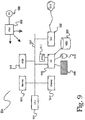
- Fig. 9 is an exemplary diagram of a computer system 900 as may be used in the system and methods disclosed herein, according to various embodiments of the invention. It is exemplary of any computer that may execute code to process data. Various modifications and changes may be made to computer system 900 without departing from the broader scope of the system and method disclosed herein.
- CPU 901 is connected to bus 902, to which bus is also connected memory 906, nonvolatile memory 904, display 907, I/O unit 908, and network interface card (NIC) 916.
- I/O unit 908 may, typically, be connected to keyboard 909, pointing device 910, hard disk 912, and real-time clock 911.
- Fig. 12 shows an application screen 1200, accessed using indicator 1105 that is exemplary of additional application functionality according to a preferred embodiment of the invention.
- boat 1201 viewed from the top, approaches dock 1202.
- Screen 1200 shows all boat fenders 1204a-n, of which in this example there are eight.
- Those fenders on the side approaching dock 1202 may be indicated, for example, by halo buttons, that is, buttons showing a halo around the fender indicating a possible user interaction.
- Screen 1200 may also contain an additional button (not shown here) that enables a user to control multiple fenders, such as, for example, all fenders together, all fenders on the side of the boat approaching the dock, all front fenders, all rear fenders, etc.
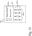
- Fig. 13 shows an exemplary application screen 1300 that may open when a user has deployed boat fenders as described in the discussion of Fig. 12 , according to a preferred embodiment of the invention.
- Represented on screen 1300 is one side 1301 of the boat, with fenders 1302a-n.
- fenders 1302a-n Above and below fenders 1302a-n are arrows 1303a-n, indicating fender movement up or down.
- Buttons 1304a-n give a user control of general functions, such as, for example, deploying all fenders to a default position or saving a manually controlled position as a new default position.
- Individual fender positions may be manually controlled by pressing any of arrows 1303a-n to adjust any one fender up or down as desired.
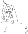
- Fig. 14 shows an exemplary representation of a boat prow 1400 where a receptacle 1402 is mounted on one or more hinges 1403, according to a preferred embodiment of the invention.
- This figure shows many structures found at the prow of the boat, including railing 1405, prow 1401 with cabin windows, and other features.
- Exemplary receptacle 1402 is, in this example, mounted behind railing 1405, with mounting hinges 1403a, b on the inside of railing 1405.
- Chute 1404 is attached to receptacle 1402, so the fender within receptacle 1402 may slide down against the boat side. Deploying and retracting the fender may be done manually, with, for example, a line, or by a motor.
- chute 1404 may have a small lip, so the fender can easily be retracted back up into receptacle 1402. In other cases, chute 1404 may be recessed behind the farthest extension of the outward vertical curve of prow 1400, thus not protruding into the line of travel (up and down) of the fender.
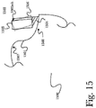
- Fig. 15 shows an exemplary cross section 1500 of a boat 1501 with a representative receptacle secured by mounting hinges and a chute that aids in deployment, according to a preferred embodiment of the invention.
- the outlines of boat 1501, prow section 1507 on top, walkway 1508 behind the railing, and the hull are all, for reasons of clarity and simplicity, very simplified.
- Receptacle 1502, secured by mounting hinges 1503a, b, and chute 1504 are slightly behind the outermost part of the hull of boat 1501, because fender 1505 is heavy enough to slip over the edge of boat 1501 when it is deployed. Deploying and retracting fender 1505 may be done manually, with, for example, a line, or by a motor.
- Outline 1506 shows an alternative receptacle 1502 position, wherein receptacle 1502 may be hinged around the railing so that during deployment and retraction of fender 1505, the receptacle bottom tilts slightly outward.
- Fig. 16 shows a diagram of an alternative arrangement 1600 by which receptacle 1603 may be recessed, according to a preferred embodiment of the invention. Shown are walkway 1607, behind railing 1602, and prow 1601. Railing 1602 has a notch or bay 1606 in the inner edge so fender receptacle 1603 can retract in large part behind the outline of the railing.
- hinge 1604 enables receptacle 1603 in position 1603a to swing out into position 1603b.
- Arm 1605 shown in position 1605a retracted and in position 1605b extended, may be operated manually, with, for example, a lever or knob, a line, a spring or by a motor, and the like.
- Deploying and retracting the fender may also be done manually, with, for example, a line, or by a motor, as described earlier herein.
- Arm 1605 in extended position 1605b, pushes receptacle 1603 into position 1603b, so the fender can deploy vertically without hitting the deck or railing.
- a bay or notch 1606 may be flanked by one or two posts, enabling additional hinges to further control the swing of receptacle 1603 (not shown).
- arm 1605 may retract receptacle 1603 to a position behind the boat's outline.
- Moveable bar 1705 has three openings. These openings 1708a and 1708b are at each end, for riding up and down receptacle bars 1707 and 1706, as well as one opening 1709, which is roughly in the center, for guiding line 1710 to which fender 1711 is attached. In the fully extended position, moveable bar 1705 is stopped at the bottom end of the receptacle, across the receptacle opening.
- fender 1711 As the fender 1711 is retracted, it catches moveable bar 1705 when it reaches opening 1709 and pushes bar 1705 up as fender 1711 is fully retracted, bar 1705 being moveable along the cylindrical axis of receptacle 1701.
- boat name 1712 in alphanumeric characters, may be applied in desired color(s) and finishes.
- receptacle 1701 may contain a camera (not shown) that provides a close-up view of the pier to the controlling tablet and or smartphone, helping to "fine-maneuver" the boat into the desired docking position.
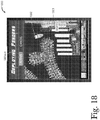
- Fig. 18 shows an exemplary fender deployment reminder pop-up screen 1800 according to a preferred embodiment of the invention.
- a marked location such as a previously visited landing place.
- the question of whether to deploy or not, if no prior default was set appears at the top of screen 1800.
- the user can then issue the command by clicking either one of the response buttons 1803a-n.
- this example shows two buttons 1803, there could be more, such as, for example, more than one deploy button, one for the standard height, and one or more for other options.
- Fig. 19 shows a screenshot 1900 in which the system prompts the user whether to remember a decision regarding fender deployment. Specifically, the system prompts the user whether to remember the decision from screen 1800 for the next time the vessel approaches the same location, by selecting either one of the response buttons 1901a-b.
- Alternative configuration 2001e shows, instead of an added resistor 2002, that the switching transistor 2004 driving motor 708 between contact points F and G is used as the measuring resistor, and the amplifier 2005 drives the voltage H. Also, point I drives the transistor.
- Both configurations 2001a and 2001e are commonly used approaches to measuring currents or protecting motors and/or other circuitry elements from overload and are not novel in and of themselves. However, the use of motor overloads to detect entanglement with respect to the fender, and in particular to aid with untangling, is novel.
- Fig. 21 shows a modified version of Fig. 17 , according to one aspect of the system and method described herein.
- camera 2101 is attached by stick 2102.
- Wire 2103 connects to controller box 1701, enabling transmission of images from the camera to show when the fender is lowered.
- camera view field 2104 can observe the state of the fender, such as, for example, if the fender is stuck on the sea bottom, if the fender line is tangled, etc.
- wire 2103 could be run within stick 2012, or the camera could be placed in a bulge out of the top of controller 1701, etc.
- Various different cameras and viewing angles may be used to provide the best views of a problem.
- the camera explicitly observes a tangle. It can be used, for example, simply to see whether the protection circuitry described above in the discussion of Fig. 20 has stopped the motor due to difficulty in raising the fender.
- visual recognition software may be embedded in the camera module or in the central controller, so the system can identify either a tangle or a lack of motion of the fender, which, when the motor should be in motion, indicates highly likely a tangle or similar problem.
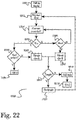
- Fig. 22 shows an exemplary process 2200 for resolving problems with raising the fender, employing the two novel approaches disclosed above in the discussions of Figs. 20 and 21 , according to one aspect of the system and method disclosed herein.
- the system receives a command to pull up the fender.
- the system sets a maximum time to attempt to pull up the fender, and in step 2203, the system monitors the time to determine when the current attempt exceeds the preset maximum time. If, in step 2204, the system determines that the current attempt has exceeded the preset maximum time, in step 2205 the system checks to see if an End switch, such as, for example, switch 711 described in the discussion of Fig.
- an End switch such as, for example, switch 711 described in the discussion of Fig.
- End switch 711 is activated, signaling that the fender is fully retracted.
- various switching means may be used as an End switch 711 according to the invention; for example, conventional contact-based electrical switches, radio frequency identification (RFID) proximity switches, mechanical switches, magnetic switches, or any other similar means of detecting when a fender is fully retracted.
- RFID radio frequency identification
- more than one end switch may be utilized in some arrangements, for example to increase reliability if the fender is retracted at an angle, or to provide redundancy should any single switch fail (for example, due to damage to the receptacle). If the End switch is activated, indicating that the fender or movable bar is fully retracted, in step 2206 the process ends.
- step 2205 if the system detects that the End switch is not activated, in step 2207 the system initiates a check for a tangle in the fender line.
- step 2210 the system checks to determine the number of tangle checks, such as, for example, the first occurrence of a tangle check, or any number up to a preset maximum. Typically, only one or two attempts to detangle would occur, to avoid damage to the equipment. If, in step 2210 the detangle attempts do not exceed the preset limit, in step 2211 the system attempts to detangle the line, typically by a little tug or pull on the line, as would be done manually. After each detangle attempt in step 2211, the system returns to step 2202 to repeat the process.
- step 2208 the system again checks to see if the maximum time or number of attempts has been exceeded. If the detangle attempts fail repeatedly, in step 2209 the system attempts a visual check of the fender, using the camera as described in the discussion of Fig. 21 . When the visual check is finished, the system once again attempts a detangle. If all system detangle attempts fail, the system issues a call for operator help in step 2212, and in step 2213 the process ends. Different strategies for detangling may be used, for example resulting in controlled jerking of the line and or the fender in order to resolve the tangle or jam. There may also time limits for individual sets of detangling and overall attempts in order to protect the components of the system from overload/damage. Further, failure to complete retraction may result in an alert sent to an operator or other predetermined location or person.
- the system upon retracting the fender, the system shuts off the motor if an over-current arises due to a tangle in the line or a catch of the fender below the receptacle. Upon such a shutdown of the motor, the system engages in a limited number of small reversals in an attempt to detangle the line and/or the fender and achieve a full retraction. Additionally, a camera and visual recognition software may be used to detect a tangle or other problem with the line or the fender, in addition to the current sensing.
- the motor shuts off if a disturbance in the retraction motion is recognized by the visual recognition software due to a tangle in the line or a catch of the fender below the receptacle.
- the system engages in a limited number of reversals to attempt to detangle the line and or the fender and achieve a full retraction.
- the current control may be used to aid the detangling control of the reversal of the line motion in addition to the camera. Different strategies for detangling may be used. There may also time limits for individual sets of detangling and overall attempts in order to protect the components of the system from overload/damage. Further, failure to complete retraction may result in an alert sent to an operator or other predetermined location or person.
- Fig. 23 shows exemplary embodiments of the invention adapted to provide heavy swell protection for boat fender system 2300.
- storms or other disturbances may occur that result in the production of heavy swells or waves.
- These swells can possess enough energy to damage the machinery of either manually operated or motor operated fender systems, particularly when sudden movement of a vessel causes substantial tension to be applied suddenly to any cable holding a fender in place, thereby placing large and sudden stresses on the machinery of fender systems.
- Spring 2303 acts as a buffer between fender 2301 and the rest of the system. While a spring is shown and described, one knowledgeable in the art will realize that other elastic members (such as, but not limited to, bungee cords or bungee cables) could be used for the purpose of swell mitigation.
- fender 2304 is equipped with a detached top 2307 which can move freely from the rest of fender 2304. Detached top 2307 is attached to the rest of fender 2304 by a spring 2306 internal to fender 2304; spring 2306 has a point of attachment to fender 2304 at its lower end, in the interior of fender 2304.
- spring 2304 serves to buffer the forces by allowing the top of the fender to partially separate temporarily until the stress is relieved. Detached fender top 2307 is then attached to a line 2305 that goes to the rest of the system. Alternatively, an internal spring 2306 may be used without detached top 2307, in which case spring 2306 may be connected directly to line 2305. It should be clear that the examples depicted in these figures are relatively simple configurations practical to clearly show the functional aspects of the system; other structures and parts such as but not limited to protective encasements, retainers, correct mounting hardware, drains, and guides are not depicted. Relative lengths or sizes of the parts are not meant to be to scale for operation.
- lowering of the rate of raising of fender 1711 into receptacle 1701 would typically occur as the top of fender 1711 enters the lower ring of receptacle 1701.
- Other variations are clearly possible, according to the invention, as will be appreciated by one having ordinary skill in the art.
- fender 2304 is equipped with a detached top 2307 which can move freely from the rest of fender 2304. Detached top 2307 is attached to the rest of fender 2304 by a spring 2306 internal to fender 2304; spring 2306 has a point of attachment to fender 2304 at its lower end, in the interior of fender 2304. In times of heavy force upon fender 2304 by a swell, spring 2304 serves to buffer the forces by allowing the top of the fender to partially separate temporarily until the stress is relieved.
- Detached fender top 2307 is then attached to a line 2305 that goes to the rest of the system.
- an internal spring 2306 may be used without detached top 2307, in which case spring 2306 may be connected directly to line 2305.
- the rate of raising fender 1711 may be slowed when fender 1711 approaches an intermediate position; that is, intermediate between a deployed position and a stowed position.
- the rate of raising fender 1711 is reduced, to reduce the likelihood of fouling and to potentially reduce the impact resulting from any misalignment, fouling, or other problem. It will be recognized by one having ordinary skill in the art that various means of detecting when to change (e.g., reduce) the rate of raising of fender 1711 may be used according to the invention.
Landscapes
- Engineering & Computer Science (AREA)
- Ocean & Marine Engineering (AREA)
- Radar, Positioning & Navigation (AREA)
- Remote Sensing (AREA)
- Physics & Mathematics (AREA)
- General Physics & Mathematics (AREA)
- Chemical & Material Sciences (AREA)
- Combustion & Propulsion (AREA)
- Mechanical Engineering (AREA)
- Emergency Alarm Devices (AREA)
- Position Fixing By Use Of Radio Waves (AREA)
Claims (14)
- Ein System (200) für das automatische Ausfahren mindestens eines Bootsfenders (713) zum Schutz eines Bootsrumpfes, umfassend:mindestens einen Fenderbehälter (706), jeder des mindestens einen Fenderbehälters ist konfiguriert, einen Bootsfender in einer verstauten Position zu halten und ferner konfiguriert, den Bootsfender aus der verstauten Position in eine ausgefahrene Position abzusenken, in der der Bootsrumpf geschützt werden kann;wobei der mindestens eine Bootsfender an einer Leine (712) befestigt ist, die Leine ist mit einer Winde (709) verbunden, die Winde ist mit einem Motor (708) gekoppelt; undein Systemsteuergerät (704) umfasst eine Vielzahl von Softwareprogrammierungsanweisungen, die in einem Speicher abgelegt sind und in einem Prozessor eines Computergeräts ausgeführt werden;wobei das Systemsteuergerät den Motorbetrieb steuert, und wobei das Systemsteuergerät GPS-Daten für das Boot empfängt, und eine Höhe der Fender einstellt, die am Standort ausgefahren werden, oder eine Eingabeaufforderung anzeigt, um den Bootsfender anzuheben oder abzusenken, die Eingabeaufforderung basiert, mindestens teilweise, auf den GPS-Daten; und wobei das Systemsteuergerät, auf Basis der Eingabeanweisungen, den Motor steuert, um den Bootsfender in die ausgefahrene Position abzusenken, wenn das Boot an einem vorbestimmten Abstand von einem Kai ankommt, oder den Fender aus der ausgefahrenen Position anzuheben, wenn das Boot einen vorbestimmten Abstand vom Kai erreicht hat.
- Das System nach Anspruch 1, wobei das Computergerät entweder ein Smartphone oder ein Tablett-Computergerät ist.
- Das System nach Anspruch 1 oder 2, wobei das Systemsteuergerät in einem Boot installiert ist und an Bord betrieben wird und ferner konfiguriert ist, den Betrieb des Motors oder jedes einzelnen Motors automatisch ohne Benutzerinteraktion zu steuern, der Betrieb wird mindestens teilweise auf der Grundlage einer Vielzahl von gespeicherten Betriebsanweisungen gesteuert.
- Das System nach einem der vorhergehenden Ansprüche, wobei das Systemsteuergerät konfiguriert ist, eine Vielzahl von GPS-Daten zu empfangen, und konfiguriert ist, eine Eingabeaufforderung an einen Benutzer auszugeben, die Eingabeaufforderung basiert mindestens teilweise auf einem Teil der Vielzahl von GPS-Daten, und konfiguriert ist, eine Vielzahl von Benutzereingaben zu empfangen, und konfiguriert ist, mindestens einen Teil der empfangenen Benutzereingaben zu speichern.
- Das System nach einem der Ansprüche 1 - 5, ferner umfassend eine Motor-Bedieneinheit, die eine Vielzahl von Programmierungsanweisungen umfasst, die in einem Speicher abgelegt sind und auf einem Prozessor eines Computergeräts ausgeführt werden, und das konfiguriert ist, den Betrieb eines Motors zu steuern.
- Das System nach Anspruch 5, wobei die Motor-Bedieneinheit ferner konfiguriert ist, den Betrieb einer Vielzahl von Steuergeräten zu steuern.
- Das System nach Anspruch 1, wobei das Computergerät ferner ein Mobilgerät umfasst, das einen Prozessor, einen Speicher und eine Anwendung mit programmierbaren Anweisungen umfasst, die im Speicher abgelegt sind und im Prozessor ausgeführt werden, die Anwendung hat Zugang zu einem Kartensystem und zu den GPS-Systemdaten, wobei die Anwendung von einem Benutzer eingesetzt werden kann, um einen Standort hinzuzufügen, der von einem Wasserfahrzeug für das Anlegen genutzt wird, und wobei der Benutzer eine Markierung eingeben kann, die eine Höhe der Fender, die am Standort ausgefahren werden, repräsentiert.
- Das System nach Anspruch 7, wobei sich die Anwendung an eine Entscheidung des Benutzers erinnert, ob oder ob nicht und wie die Fender ausgefahren werden.
- Das System nach einem der Ansprüche 1 - 8, wobei beim Einfahren des Fenders, der Motor konfiguriert ist, Stromschwankungen zu erfassen, und konfiguriert ist, seinen Betrieb zu verändern, wenn ein Überstromzustand festgestellt wird, die Erfassung des Überstroms basiert mindestens teilweise auf einer konfigurierten Strombegrenzung.
- Das System nach Anspruch 9, wobei beim Abschalten des Motors, das von einer Verwicklung der Leine verursacht wird, das System versucht, die Leine zu entwirren und eine vollständige Aufwicklung zu erreichen, das Entwirren umfasst dabei eine Umkehrung der Leinenbewegung.
- Das System nach Anspruch 10, wobei eine Kamera (2101) in Verbindung mit einer visuellen Erkennungssoftware eingesetzt wird, um die Entwirrungssteuerung der Leinenbewegung zusätzlich zur Strommessung zu unterstützen.
- Das System nach Anspruch 10 oder 11, wobei einem Bediener ein Alarm angezeigt wird, wenn das Einfahren des Fenders nach der Anzahl an Umkehrungsversuchen fehlschlägt.
- Das System nach einem der Ansprüche 1 - 13, wobei der Behälter entweder ein Behälter ist, der an einem Rumpfteil des Bootes angebracht oder ein fest im Bootsrumpf eingebautes Fach ist.
- Ein Verfahren zum Ausfahren mindestens eines Bootsfenders (713), um einen Bootsrumpf zu schützen, in einem System, das Folgendes umfasst:Mindestens einen Fenderbehälter (706), jeder des mindestens einen Fenderbehälters ist konfiguriert, einen Bootsfender in einer verstauten Position zu halten und ferner konfiguriert, den Bootsfender aus der verstauten Position in eine ausgefahrene Position abzusenken, in der der Bootsrumpf geschützt werden kann;wobei mindestens ein Bootsfender an einer Leine (712) befestigt ist, die Leine ist mit einer Winde (709) verbunden, die Winde ist mit einem Motor (708) gekoppelt; und ein Systemsteuergerät (704) umfasst eine Vielzahl von Softwareprogrammierungsanweisungen, die in einem Speicher abgelegt sind und in einem Prozessor eines Computergeräts ausgeführt werden;wobei das Systemsteuergerät den Motorbetrieb steuert, undwobei das Systemsteuergerät GPS-Daten für das Boot empfängt, und eine Höhe der Fender einstellt, die am Standort ausgefahren werden, oder eine Benutzereingabeaufforderung anzeigt, um den Bootsfender anzuheben oder abzusenken, die Eingabeaufforderung basiert, mindestens teilweise, auf den GPS-Daten; undwobei das Systemsteuergerät, auf Basis der GPS-Daten, den Motor steuert, um den Bootsfender in die ausgefahrene Position abzusenken, wenn das Boot an einem vorbestimmten Abstand von einem Kai ankommt.
Applications Claiming Priority (10)
| Application Number | Priority Date | Filing Date | Title |
|---|---|---|---|
| US201562148725P | 2015-04-16 | 2015-04-16 | |
| US201562153193P | 2015-04-27 | 2015-04-27 | |
| US201562153185P | 2015-04-27 | 2015-04-27 | |
| US201562157857P | 2015-05-06 | 2015-05-06 | |
| US201562165798P | 2015-05-22 | 2015-05-22 | |
| US201562200089P | 2015-08-02 | 2015-08-02 | |
| US14/929,369 US9440716B1 (en) | 2015-04-27 | 2015-11-01 | Enhanced system and method for automatically deploying boat fenders |
| US14/981,858 US9598157B2 (en) | 2015-04-16 | 2015-12-28 | Enhanced system and method for detangling and protection of automatic fender positioning systems |
| US15/054,125 US9409637B1 (en) | 2015-04-16 | 2016-02-25 | Enhanced system and method for remotely deploying boat fenders |
| PCT/US2016/026271 WO2016168025A1 (en) | 2015-04-16 | 2016-04-06 | Enhanced system and method for detangling and protection of automatic fender positioning systems |
Publications (3)
| Publication Number | Publication Date |
|---|---|
| EP3283364A1 EP3283364A1 (de) | 2018-02-21 |
| EP3283364A4 EP3283364A4 (de) | 2018-11-14 |
| EP3283364B1 true EP3283364B1 (de) | 2020-07-22 |
Family
ID=57126422
Family Applications (1)
| Application Number | Title | Priority Date | Filing Date |
|---|---|---|---|
| EP16780474.9A Active EP3283364B1 (de) | 2015-04-16 | 2016-04-06 | Erweitertes system und verfahren für entwirrung und schutz von automatischen kotflügelpositionierungssystemen |
Country Status (3)
| Country | Link |
|---|---|
| EP (1) | EP3283364B1 (de) |
| CA (1) | CA2982936C (de) |
| WO (1) | WO2016168025A1 (de) |
Cited By (2)
| Publication number | Priority date | Publication date | Assignee | Title |
|---|---|---|---|---|
| US12459618B2 (en) | 2021-12-22 | 2025-11-04 | Navico, Inc. | Device for steering a trolling motor and method of the same |
| US12662226B2 (en) | 2021-12-22 | 2026-06-23 | Navico, Inc. | Remote trolling motor steering control |
Families Citing this family (1)
| Publication number | Priority date | Publication date | Assignee | Title |
|---|---|---|---|---|
| CN110000792B (zh) * | 2019-04-26 | 2020-08-21 | 西湖大学 | 船壁清洗机器人的路径调整方法、装置、设备及存储介质 |
Family Cites Families (9)
| Publication number | Priority date | Publication date | Assignee | Title |
|---|---|---|---|---|
| US497980A (en) | 1893-05-23 | Sawing-machine | ||
| JPS5852878B2 (ja) * | 1979-12-03 | 1983-11-25 | 三井造船株式会社 | 半没水型多胴船 |
| SU1054189A1 (ru) * | 1982-03-05 | 1983-11-15 | Предприятие П/Я А-1277 | Гравитационное устройство дл хранени и постановки швартовного кранца судна |
| US4970980A (en) * | 1989-06-26 | 1990-11-20 | Eisner Nathan A | Inflatable bumper system for water craft |
| NL1018604C2 (nl) * | 2001-07-20 | 2003-01-21 | B O U W Beerdsen B V | Inrichting voor het in hoogte verstellen van op een vaartuig aangebrachte stootwillen. |
| GB2381845B (en) * | 2001-11-09 | 2005-02-09 | Lorna Anne Robson | Integrated fendering sytem |
| US6758155B1 (en) | 2002-06-05 | 2004-07-06 | Watson C. Nicholas | Fender retrieval system |
| WO2007021169A1 (en) * | 2005-08-17 | 2007-02-22 | Tomtom International B.V. | Navigation device and method of scrolling map data displayed on a navigation device |
| JP4221054B2 (ja) * | 2006-10-31 | 2009-02-12 | 横浜ゴム株式会社 | 操船および船舶係留支援方法並びにそのシステム |
-
2016
- 2016-04-06 EP EP16780474.9A patent/EP3283364B1/de active Active
- 2016-04-06 WO PCT/US2016/026271 patent/WO2016168025A1/en not_active Ceased
- 2016-04-06 CA CA2982936A patent/CA2982936C/en active Active
Non-Patent Citations (1)
| Title |
|---|
| None * |
Cited By (2)
| Publication number | Priority date | Publication date | Assignee | Title |
|---|---|---|---|---|
| US12459618B2 (en) | 2021-12-22 | 2025-11-04 | Navico, Inc. | Device for steering a trolling motor and method of the same |
| US12662226B2 (en) | 2021-12-22 | 2026-06-23 | Navico, Inc. | Remote trolling motor steering control |
Also Published As
| Publication number | Publication date |
|---|---|
| CA2982936C (en) | 2020-11-03 |
| CA2982936A1 (en) | 2016-10-20 |
| EP3283364A4 (de) | 2018-11-14 |
| EP3283364A1 (de) | 2018-02-21 |
| WO2016168025A1 (en) | 2016-10-20 |
Similar Documents
| Publication | Publication Date | Title |
|---|---|---|
| US10266242B2 (en) | Enhanced system and method for detangling and protection of automatic fender positioning systems | |
| US9409637B1 (en) | Enhanced system and method for remotely deploying boat fenders | |
| US10981634B2 (en) | Enhanced system and method for remotely deploying boat fenders | |
| US9598157B2 (en) | Enhanced system and method for detangling and protection of automatic fender positioning systems | |
| US12240572B2 (en) | System and method for controlling motorized boat fender deployment and retrieval systems | |
| US20210229781A1 (en) | System and method for boat fender deployment | |
| US9738358B2 (en) | Enhanced system and method for deploying boat fenders safely and conveniently | |
| EP3604110B1 (de) | System und verfahren zur positionierung von kotflügeln mit reduzierter komplexität | |
| US10351218B2 (en) | Enhanced system and method for remotely deploying boat fenders | |
| CA2982936C (en) | Enhanced system and method for detangling and protection of automatic fender positioning systems | |
| US20110023770A1 (en) | Intelligent boat lift system | |
| CN107344597B (zh) | 无人船布放回收装置、系统以及无人船布放回收方法 | |
| US6758155B1 (en) | Fender retrieval system | |
| US10569871B2 (en) | Apparatus, device and method for automated launch and recovery of a kite | |
| CN105000479A (zh) | 具有升沉补偿和张力保护功能的缆控潜水器甲板吊放系统 | |
| US11072402B2 (en) | Reduced-complexity fender positioning system and method | |
| CN116142390A (zh) | 一种止荡对接装置及其水下设备吊放回收系统 | |
| KR20190101956A (ko) | 선박용 보조 돛 시스템 및 그에 대한 안전 시스템 | |
| US9937985B2 (en) | System and method for planning and predetermination of fender heights and dock location information | |
| EP3883848A1 (de) | System zum übertragen eines objekts von einem schiff auf eine offshore-struktur | |
| US9731800B2 (en) | Enhanced system and method for controlling automatic deployment of boat fenders | |
| WO2017146796A1 (en) | System and method for planning and predetermination of fender heights and dock location information | |
| KR101225995B1 (ko) | 윈도우 커버 개폐장치 | |
| US11959239B1 (en) | Mechanized boat dock | |
| KR20250104940A (ko) | 수상정 진회수 장치 |
Legal Events
| Date | Code | Title | Description |
|---|---|---|---|
| STAA | Information on the status of an ep patent application or granted ep patent |
Free format text: STATUS: THE INTERNATIONAL PUBLICATION HAS BEEN MADE |
|
| PUAI | Public reference made under article 153(3) epc to a published international application that has entered the european phase |
Free format text: ORIGINAL CODE: 0009012 |
|
| STAA | Information on the status of an ep patent application or granted ep patent |
Free format text: STATUS: REQUEST FOR EXAMINATION WAS MADE |
|
| 17P | Request for examination filed |
Effective date: 20171004 |
|
| AK | Designated contracting states |
Kind code of ref document: A1 Designated state(s): AL AT BE BG CH CY CZ DE DK EE ES FI FR GB GR HR HU IE IS IT LI LT LU LV MC MK MT NL NO PL PT RO RS SE SI SK SM TR |
|
| AX | Request for extension of the european patent |
Extension state: BA ME |
|
| DAV | Request for validation of the european patent (deleted) | ||
| DAX | Request for extension of the european patent (deleted) | ||
| A4 | Supplementary search report drawn up and despatched |
Effective date: 20181016 |
|
| RIC1 | Information provided on ipc code assigned before grant |
Ipc: G05B 19/02 20060101ALI20181010BHEP Ipc: G01C 21/00 20060101ALI20181010BHEP Ipc: B63B 59/02 20060101AFI20181010BHEP Ipc: B63B 21/00 20060101ALI20181010BHEP |
|
| GRAP | Despatch of communication of intention to grant a patent |
Free format text: ORIGINAL CODE: EPIDOSNIGR1 |
|
| STAA | Information on the status of an ep patent application or granted ep patent |
Free format text: STATUS: GRANT OF PATENT IS INTENDED |
|
| INTG | Intention to grant announced |
Effective date: 20200203 |
|
| GRAS | Grant fee paid |
Free format text: ORIGINAL CODE: EPIDOSNIGR3 |
|
| GRAA | (expected) grant |
Free format text: ORIGINAL CODE: 0009210 |
|
| STAA | Information on the status of an ep patent application or granted ep patent |
Free format text: STATUS: THE PATENT HAS BEEN GRANTED |
|
| AK | Designated contracting states |
Kind code of ref document: B1 Designated state(s): AL AT BE BG CH CY CZ DE DK EE ES FI FR GB GR HR HU IE IS IT LI LT LU LV MC MK MT NL NO PL PT RO RS SE SI SK SM TR |
|
| REG | Reference to a national code |
Ref country code: GB Ref legal event code: FG4D |
|
| REG | Reference to a national code |
Ref country code: CH Ref legal event code: EP |
|
| REG | Reference to a national code |
Ref country code: DE Ref legal event code: R096 Ref document number: 602016040470 Country of ref document: DE |
|
| REG | Reference to a national code |
Ref country code: AT Ref legal event code: REF Ref document number: 1293137 Country of ref document: AT Kind code of ref document: T Effective date: 20200815 |
|
| REG | Reference to a national code |
Ref country code: IE Ref legal event code: FG4D |
|
| GRAT | Correction requested after decision to grant or after decision to maintain patent in amended form |
Free format text: ORIGINAL CODE: EPIDOSNCDEC |
|
| REG | Reference to a national code |
Ref country code: SE Ref legal event code: TRGR |
|
| REG | Reference to a national code |
Ref country code: LT Ref legal event code: MG4D |
|
| REG | Reference to a national code |
Ref country code: AT Ref legal event code: MK05 Ref document number: 1293137 Country of ref document: AT Kind code of ref document: T Effective date: 20200722 |
|
| PG25 | Lapsed in a contracting state [announced via postgrant information from national office to epo] |
Ref country code: GR Free format text: LAPSE BECAUSE OF FAILURE TO SUBMIT A TRANSLATION OF THE DESCRIPTION OR TO PAY THE FEE WITHIN THE PRESCRIBED TIME-LIMIT Effective date: 20201023 Ref country code: AT Free format text: LAPSE BECAUSE OF FAILURE TO SUBMIT A TRANSLATION OF THE DESCRIPTION OR TO PAY THE FEE WITHIN THE PRESCRIBED TIME-LIMIT Effective date: 20200722 Ref country code: ES Free format text: LAPSE BECAUSE OF FAILURE TO SUBMIT A TRANSLATION OF THE DESCRIPTION OR TO PAY THE FEE WITHIN THE PRESCRIBED TIME-LIMIT Effective date: 20200722 Ref country code: HR Free format text: LAPSE BECAUSE OF FAILURE TO SUBMIT A TRANSLATION OF THE DESCRIPTION OR TO PAY THE FEE WITHIN THE PRESCRIBED TIME-LIMIT Effective date: 20200722 Ref country code: NO Free format text: LAPSE BECAUSE OF FAILURE TO SUBMIT A TRANSLATION OF THE DESCRIPTION OR TO PAY THE FEE WITHIN THE PRESCRIBED TIME-LIMIT Effective date: 20201022 Ref country code: FI Free format text: LAPSE BECAUSE OF FAILURE TO SUBMIT A TRANSLATION OF THE DESCRIPTION OR TO PAY THE FEE WITHIN THE PRESCRIBED TIME-LIMIT Effective date: 20200722 Ref country code: LT Free format text: LAPSE BECAUSE OF FAILURE TO SUBMIT A TRANSLATION OF THE DESCRIPTION OR TO PAY THE FEE WITHIN THE PRESCRIBED TIME-LIMIT Effective date: 20200722 Ref country code: PT Free format text: LAPSE BECAUSE OF FAILURE TO SUBMIT A TRANSLATION OF THE DESCRIPTION OR TO PAY THE FEE WITHIN THE PRESCRIBED TIME-LIMIT Effective date: 20201123 Ref country code: BG Free format text: LAPSE BECAUSE OF FAILURE TO SUBMIT A TRANSLATION OF THE DESCRIPTION OR TO PAY THE FEE WITHIN THE PRESCRIBED TIME-LIMIT Effective date: 20201022 |
|
| PG25 | Lapsed in a contracting state [announced via postgrant information from national office to epo] |
Ref country code: LV Free format text: LAPSE BECAUSE OF FAILURE TO SUBMIT A TRANSLATION OF THE DESCRIPTION OR TO PAY THE FEE WITHIN THE PRESCRIBED TIME-LIMIT Effective date: 20200722 Ref country code: PL Free format text: LAPSE BECAUSE OF FAILURE TO SUBMIT A TRANSLATION OF THE DESCRIPTION OR TO PAY THE FEE WITHIN THE PRESCRIBED TIME-LIMIT Effective date: 20200722 Ref country code: RS Free format text: LAPSE BECAUSE OF FAILURE TO SUBMIT A TRANSLATION OF THE DESCRIPTION OR TO PAY THE FEE WITHIN THE PRESCRIBED TIME-LIMIT Effective date: 20200722 Ref country code: IS Free format text: LAPSE BECAUSE OF FAILURE TO SUBMIT A TRANSLATION OF THE DESCRIPTION OR TO PAY THE FEE WITHIN THE PRESCRIBED TIME-LIMIT Effective date: 20201122 |
|
| PG25 | Lapsed in a contracting state [announced via postgrant information from national office to epo] |
Ref country code: NL Free format text: LAPSE BECAUSE OF FAILURE TO SUBMIT A TRANSLATION OF THE DESCRIPTION OR TO PAY THE FEE WITHIN THE PRESCRIBED TIME-LIMIT Effective date: 20200722 |
|
| REG | Reference to a national code |
Ref country code: DE Ref legal event code: R097 Ref document number: 602016040470 Country of ref document: DE |
|
| PG25 | Lapsed in a contracting state [announced via postgrant information from national office to epo] |
Ref country code: IT Free format text: LAPSE BECAUSE OF FAILURE TO SUBMIT A TRANSLATION OF THE DESCRIPTION OR TO PAY THE FEE WITHIN THE PRESCRIBED TIME-LIMIT Effective date: 20200722 Ref country code: EE Free format text: LAPSE BECAUSE OF FAILURE TO SUBMIT A TRANSLATION OF THE DESCRIPTION OR TO PAY THE FEE WITHIN THE PRESCRIBED TIME-LIMIT Effective date: 20200722 Ref country code: SM Free format text: LAPSE BECAUSE OF FAILURE TO SUBMIT A TRANSLATION OF THE DESCRIPTION OR TO PAY THE FEE WITHIN THE PRESCRIBED TIME-LIMIT Effective date: 20200722 Ref country code: RO Free format text: LAPSE BECAUSE OF FAILURE TO SUBMIT A TRANSLATION OF THE DESCRIPTION OR TO PAY THE FEE WITHIN THE PRESCRIBED TIME-LIMIT Effective date: 20200722 Ref country code: CZ Free format text: LAPSE BECAUSE OF FAILURE TO SUBMIT A TRANSLATION OF THE DESCRIPTION OR TO PAY THE FEE WITHIN THE PRESCRIBED TIME-LIMIT Effective date: 20200722 Ref country code: DK Free format text: LAPSE BECAUSE OF FAILURE TO SUBMIT A TRANSLATION OF THE DESCRIPTION OR TO PAY THE FEE WITHIN THE PRESCRIBED TIME-LIMIT Effective date: 20200722 |
|
| PLBE | No opposition filed within time limit |
Free format text: ORIGINAL CODE: 0009261 |
|
| STAA | Information on the status of an ep patent application or granted ep patent |
Free format text: STATUS: NO OPPOSITION FILED WITHIN TIME LIMIT |
|
| PG25 | Lapsed in a contracting state [announced via postgrant information from national office to epo] |
Ref country code: AL Free format text: LAPSE BECAUSE OF FAILURE TO SUBMIT A TRANSLATION OF THE DESCRIPTION OR TO PAY THE FEE WITHIN THE PRESCRIBED TIME-LIMIT Effective date: 20200722 |
|
| 26N | No opposition filed |
Effective date: 20210423 |
|
| PG25 | Lapsed in a contracting state [announced via postgrant information from national office to epo] |
Ref country code: SK Free format text: LAPSE BECAUSE OF FAILURE TO SUBMIT A TRANSLATION OF THE DESCRIPTION OR TO PAY THE FEE WITHIN THE PRESCRIBED TIME-LIMIT Effective date: 20200722 |
|
| PG25 | Lapsed in a contracting state [announced via postgrant information from national office to epo] |
Ref country code: SI Free format text: LAPSE BECAUSE OF FAILURE TO SUBMIT A TRANSLATION OF THE DESCRIPTION OR TO PAY THE FEE WITHIN THE PRESCRIBED TIME-LIMIT Effective date: 20200722 |
|
| REG | Reference to a national code |
Ref country code: NL Ref legal event code: MP Effective date: 20200722 |
|
| PG25 | Lapsed in a contracting state [announced via postgrant information from national office to epo] |
Ref country code: MC Free format text: LAPSE BECAUSE OF FAILURE TO SUBMIT A TRANSLATION OF THE DESCRIPTION OR TO PAY THE FEE WITHIN THE PRESCRIBED TIME-LIMIT Effective date: 20200722 |
|
| PG25 | Lapsed in a contracting state [announced via postgrant information from national office to epo] |
Ref country code: LU Free format text: LAPSE BECAUSE OF NON-PAYMENT OF DUE FEES Effective date: 20210406 |
|
| REG | Reference to a national code |
Ref country code: BE Ref legal event code: MM Effective date: 20210430 |
|
| PG25 | Lapsed in a contracting state [announced via postgrant information from national office to epo] |
Ref country code: LI Free format text: LAPSE BECAUSE OF NON-PAYMENT OF DUE FEES Effective date: 20210430 Ref country code: CH Free format text: LAPSE BECAUSE OF NON-PAYMENT OF DUE FEES Effective date: 20210430 |
|
| PG25 | Lapsed in a contracting state [announced via postgrant information from national office to epo] |
Ref country code: IE Free format text: LAPSE BECAUSE OF NON-PAYMENT OF DUE FEES Effective date: 20210406 |
|
| PG25 | Lapsed in a contracting state [announced via postgrant information from national office to epo] |
Ref country code: IS Free format text: LAPSE BECAUSE OF FAILURE TO SUBMIT A TRANSLATION OF THE DESCRIPTION OR TO PAY THE FEE WITHIN THE PRESCRIBED TIME-LIMIT Effective date: 20201122 |
|
| PG25 | Lapsed in a contracting state [announced via postgrant information from national office to epo] |
Ref country code: BE Free format text: LAPSE BECAUSE OF NON-PAYMENT OF DUE FEES Effective date: 20210430 |
|
| PG25 | Lapsed in a contracting state [announced via postgrant information from national office to epo] |
Ref country code: HU Free format text: LAPSE BECAUSE OF FAILURE TO SUBMIT A TRANSLATION OF THE DESCRIPTION OR TO PAY THE FEE WITHIN THE PRESCRIBED TIME-LIMIT; INVALID AB INITIO Effective date: 20160406 |
|
| PG25 | Lapsed in a contracting state [announced via postgrant information from national office to epo] |
Ref country code: CY Free format text: LAPSE BECAUSE OF FAILURE TO SUBMIT A TRANSLATION OF THE DESCRIPTION OR TO PAY THE FEE WITHIN THE PRESCRIBED TIME-LIMIT Effective date: 20200722 |
|
| PG25 | Lapsed in a contracting state [announced via postgrant information from national office to epo] |
Ref country code: MK Free format text: LAPSE BECAUSE OF FAILURE TO SUBMIT A TRANSLATION OF THE DESCRIPTION OR TO PAY THE FEE WITHIN THE PRESCRIBED TIME-LIMIT Effective date: 20200722 |
|
| PG25 | Lapsed in a contracting state [announced via postgrant information from national office to epo] |
Ref country code: MT Free format text: LAPSE BECAUSE OF FAILURE TO SUBMIT A TRANSLATION OF THE DESCRIPTION OR TO PAY THE FEE WITHIN THE PRESCRIBED TIME-LIMIT Effective date: 20200722 |
|
| PG25 | Lapsed in a contracting state [announced via postgrant information from national office to epo] |
Ref country code: TR Free format text: LAPSE BECAUSE OF FAILURE TO SUBMIT A TRANSLATION OF THE DESCRIPTION OR TO PAY THE FEE WITHIN THE PRESCRIBED TIME-LIMIT Effective date: 20200722 |
|
| PGFP | Annual fee paid to national office [announced via postgrant information from national office to epo] |
Ref country code: GB Payment date: 20260409 Year of fee payment: 11 |
|
| PGFP | Annual fee paid to national office [announced via postgrant information from national office to epo] |
Ref country code: DE Payment date: 20260410 Year of fee payment: 11 |
|
| PGFP | Annual fee paid to national office [announced via postgrant information from national office to epo] |
Ref country code: SE Payment date: 20260410 Year of fee payment: 11 |
|
| PGFP | Annual fee paid to national office [announced via postgrant information from national office to epo] |
Ref country code: FR Payment date: 20260420 Year of fee payment: 11 |