EP3279602A1 - Haltevorrichtung und verfahren zum betreiben eines lenkflugkörpersystems - Google Patents
Haltevorrichtung und verfahren zum betreiben eines lenkflugkörpersystems Download PDFInfo
- Publication number
- EP3279602A1 EP3279602A1 EP17177229.6A EP17177229A EP3279602A1 EP 3279602 A1 EP3279602 A1 EP 3279602A1 EP 17177229 A EP17177229 A EP 17177229A EP 3279602 A1 EP3279602 A1 EP 3279602A1
- Authority
- EP
- European Patent Office
- Prior art keywords
- parallelogram
- holding device
- projectile
- pin
- receiving device
- Prior art date
- Legal status (The legal status is an assumption and is not a legal conclusion. Google has not performed a legal analysis and makes no representation as to the accuracy of the status listed.)
- Granted
Links
Images


Classifications
-
- F—MECHANICAL ENGINEERING; LIGHTING; HEATING; WEAPONS; BLASTING
- F41—WEAPONS
- F41F—APPARATUS FOR LAUNCHING PROJECTILES OR MISSILES FROM BARRELS, e.g. CANNONS; LAUNCHERS FOR ROCKETS OR TORPEDOES; HARPOON GUNS
- F41F3/00—Rocket or torpedo launchers
- F41F3/04—Rocket or torpedo launchers for rockets
- F41F3/052—Means for securing the rocket in the launching apparatus
Definitions
- the invention relates to a holding device for adjusting a projectile, in particular a missile, in a launching tube or launcher.
- a holding device is also referred to as a latch mechanism.
- the holding device comprises a parallelogram with a parallel to a receiving device longitudinal component, wherein a pin is arranged on the longitudinal component.
- the pin is adjustable in a transverse recess of the projectile.
- the recess may be formed perpendicular to a firing direction of the projectile.
- the pin of the parallelogram is in a stop position prior to launch of the projectile and the projectile is held in place by the pin in the launch tube.
- the pin described here is further lowered during a departure or acceleration of the projectile by the parallelogram in the receiving device. This means that the pin comes out of the recess of the projectile.
- the receiving device has a bottom surface, a top surface opposite the bottom surface and an end face, wherein the front side connects the bottom surface with the top of the receiving device.
- projectiles In defense technology autonomously acting projectiles are used to combat targets with increasing tendency. These projectiles are used depending on the application specification against light to heavy armored vehicles application. The importance of such projectiles or missiles is steadily increasing. In particular, projectiles for the shoulder closure of great importance and are constantly evolving.
- holding devices In order to prevent the projectile from falling out during transport of the projectile in a guided missile system, holding devices are known.
- the holding device holds the projectile in the launching tube or launcher both during transport and during a briefing phase of a shoot.
- the parallelogram In current holding devices, in particular Latch mechanisms used in guided missile systems, the parallelogram is accelerated so much during the outgoing of the projectile that it strikes the receiving device so strongly that it is catapulted back towards the projectile.
- the pin located on the parallelogram exerts a negative pitching moment - a so-called pitch down moment - on the projectile. This is due in particular to the fact that when accelerating the projectile, the parallelogram is lowered into the receiving device so fast or accelerated that the parallelogram and thus the pin in the direction of its initial position or holding position thrown back, back, or legislativekatapultiert. In this case, the pin located on the parallelogram hits the projectile accelerated in the firing direction and causes the pitch down moment described here.
- a holding device of the aforementioned type wherein the receiving device comprises a safety gear, wherein the parallelogram after lowering can be fixed by the safety gear.
- the catching device can prevent the parallelogram and the pin from being thrown back, back or catapulted back.
- the solution of the task is essentially to further develop the receiving device and to provide with the safety gear. Furthermore, a guided missile system can be operated by the holding device according to the invention.
- the invention provides a holding device according to claim 1 and a method for operating a guided missile system according to claim 10.
- the parallelogram comprises four joints, wherein by the four joints, a movable, parallel true displacement of the pin is feasible. That means that the pin by a Parallelogram from the recess of the projectile occurs or leaves.
- the holding device can be particularly space-saving integration in particular in the guided missile system.
- the safety gear is designed as a snap device with a shaft on the end face of the receiving device.
- the front side of the receiving device can be arranged in particular in the firing direction of the projectile.
- the snap device holds the pin in its final position after lowering the parallelogram.
- the snap device has a slight resistance, so that the snap device when lowering the parallelogram with little force is wegdgurbar.
- a torsion spring can be used which can be integrated via a pivot point of the snap device.
- a contact surface was formed, which is aligned in the unloaded state in a 90 ° position to the bottom surface of the receiving device and may be remote from the end face of the receiving device.
- the safety gear is designed as a spring hook on the front side of the receiving device.
- the spring hook hooks at least partially on an upper edge of the longitudinal component of the parallelogram.
- the pin is arranged on the upper edge.
- the catching device is designed as a spring, which is arranged between an underside of the longitudinal component and the bottom surface of the receiving device.
- the spring is designed as a torsion spring.
- At least one corner region of the longitudinal component facing away from the upper edge of the longitudinal component can be rounded off in the lowering direction of the parallelogram. This makes it easier to hook in particular when lowering the parallelogram.
- an upper edge of the longitudinal component terminates flush with the upper side of the receiving device after the parallelogram has been lowered.
- the safety gear can be arranged particularly easily in the receiving device.
- a plane can be predefined in which the spring hook or the snap device hooks or snaps onto the upper edge of the longitudinal component for fixing the parallelogram.
- the spring or spring hooks are formed from a spring steel.
- Spring steel is also stainless and heat resistant, making spring steel particularly suitable for use as a safety gear.
- the parallelogram can be controlled by an integrated communication device.
- the integrated communication device is arranged on the longitudinal component of the parallelogram.
- the parallelogram can be decoupled from its holding position by the integrated communication device which, for example, communicates with the parallelogram via a common interface shortly before the projectile leaves.
- the projectile can be adjusted safely in the launch tube during transport as well as during a briefing phase of a shoot.
- the pin is formed on one of the transverse recess facing side spherical. Due to the spherical configuration of the pins, tilting of the pins during insertion into the recess can be avoided.
- FIG. 1a-1c show schematic representations of a conventional holding device in a holding position ( Fig. 1a ), in a position during a departure of a projectile ( Fig. 1b ) and an end position ( Fig. 1c ).
- Exemplary shows the 1a a holding device 100 and a projectile 50 in a holding position.
- the projectile 50 may, for example, be a missile and is located in a launching tube 4.
- the holding device described here is particularly suitable for use in guided missile systems 200.
- the reference numeral 20 of the holding device 100 denotes a parallelogram, wherein a longitudinal component 22 of the parallelogram 20 extends parallel to a receiving device 30.
- the longitudinal component 22 may be connected, for example, by means of two connecting legs 23 with the receiving device 30.
- a pin 21 is arranged.
- the pin 21 is in the holding position in a recess 10 of the projectile 50.
- the parallelogram 20 comprises four joints G1, G2, G3, G4, wherein by the four joints G1, G2, G3, G4, a movable, parallel true displacement of the pin 21 is feasible.
- the connecting legs 23 make a right angle to the longitudinal component 22, the projectile 50 being adjustable by the pin 21 in the launching tube 4. That is, by the pin 21, the projectile 50 is held in the launching tube 4.
- the longitudinal component 22 of the parallelogram 20 further includes an integrated communication device 60 through which the parallelogram 20 is controllable.
- the Fig. 1b shows the holding device 100 during a departure of the projectile 50 in the firing direction A1.
- the connecting legs 23 incline here in the firing direction A1 or exit direction of the projectile 50.
- the parallelogram 20 is lowered into the receiving device 30 and the pin 21 leaves the recess 10 of the projectile 50th
- the Fig. 1c shows the holding device 100 in the end position.
- the parallelogram 20 is completely lowered into the receiving device 30 and the connecting legs 23 extend substantially parallel to the upper edge 25 of the longitudinal component 22.
- the parallelogram 20 is accelerated so much by the exit of the projectile 50, which hits it so strongly at its end position that in particular the pin 21 is catapulted back in the direction of the projectile 50 (see arrow in the direction of Projectile Z1).
- the pin 21 again strikes the projectile 50 still located in the firing tube 4, whereby a pitch down moment is induced.
- the pitch-down moment can bring the projectile from a trajectory calculated in advance of the departure.
- the holding device 100 comprises the receiving device 30 with a safety gear 40, wherein the parallelogram 20 can be fixed after lowering by the safety gear 40 (see Fig. 2a-2b . 3 and 4 ).
- the safety gear 40 prevents the return of the pin 21 after lowering the parallelogram 20 in the receiving device 30 and reaching the end position.
- the receiving device 30 has a bottom surface 32, a bottom surface 32 opposite the top 33 and an end face 31, wherein the end face 31 connects the bottom surface 32 with the top 33 of the receiving device 30.
- FIG. 2a . b show schematic representations of a holding device with a detailed representation of a safety gear in a holding position ( Fig. 2a ) and an end position ( Fig. 2b ) according to a first embodiment.
- Reference numeral 100 denotes a holding device in the holding position.
- the safety gear 40 is designed as a snap device 45 with a shaft 46 on the end face 31 of the receiving device 30.
- the end face 31 of the receiving device 30 is arranged in the firing direction A1 of the projectile 50.
- the connecting legs 23 in the holding position with the top 33 of the receiving device 30 form a right angle.
- a corner region 27 of the longitudinal component 22 facing away from an upper edge 25 of the longitudinal component 22 is rounded off in the lowering direction of the parallelogram 20. This makes it easier to hook in particular when lowering the parallelogram 20.
- Reference numeral 100 denotes a holding device in the end position. In the end position, the connecting legs 23 are substantially parallel to the upper side 33 of the receiving device 30.
- the snap device 45 holds the pin 21 in its final position after lowering the parallelogram 20.
- the snap device 45 has a slight resistance, so that the snap device 45 is wegdschreibbar when lowering the parallelogram 20 with as little force. At the same time, however, it is necessary to set the resistance such that snapping the Snap device 45 is correspondingly fast in order to prevent the slinging back, recoil or Zuschkatapultieren the parallelogram.
- a torsion spring 47 for example a coil spring or bar spring can be used, which can be integrated over a pivot point of the snap device 45.
- a contact surface 48 is formed, which is aligned in the unloaded state in the 90 ° position to the bottom surface 32 of the receiving device 30.
- the snap device 45 also has a projection 49, which projects at least partially over the contact surface 48 and is provided for hooking or snapping the snap device 45 on the upper edge 25 of the longitudinal component 22.
- the projection 49 with the contact surface 48 encloses a right angle.
- Fig. 3 shows a schematic representation of a holding device with a detailed illustration of a safety gear according to a second embodiment.
- Reference numeral 100 denotes a holding device in the end position.
- the safety gear 40 is attached as a spring hook 16 on the end face 31 of the receiving device 30.
- the spring hook 16 hooks at least partially on the upper edge 25 of the longitudinal component 22 of the parallelogram 20 a.
- On the upper edge 25 of the pin 21 is arranged.
- the parallelogram 20 can be caught or fixed in its final position.
- the spring hook 16 is pressed during the lowering of the parallelogram 20 in the direction of the end face 31, and as soon as the spring hook 16 slips over the upper edge 25 of the longitudinal component 22, it springs back into its original position. That is, the spring hook 16 prevents the Zuschkatapultieren the parallelogram 20 and the pin 21st
- the upper edge 25 of the longitudinal component 22 is flush after lowering the parallelogram 20 flush with the top 33 of the receiving device 30 from.
- the safety gear 40 can be arranged particularly easily in the receiving device 30.
- a plane E1 can thereby be predefined in which the spring hook 16 or the snap device 45 hooks or snaps onto the upper edge 25 of the longitudinal component 22 for fixing the parallelogram 20.
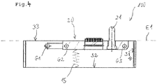
- Figure 4 shows a schematic representation of a holding device with a detailed illustration of a safety gear according to a third embodiment.
- Reference numeral 100 denotes a holding device in the end position.
- the safety gear 40 is in Fig. 4 as a spring 15, which is arranged between a bottom 26 of the longitudinal component 22 and the bottom surface 32 of the receiving device 30 is formed.
- the spring 15 for example a helical spring, after lowering the parallelogram 20, a return catapulting of the pin 21 can be prevented.
- the concept of the receiving device 30 with the catcher 40 can be extended to a variety of other applications such as mechanical components and is therefore not limited to missile systems.
- the invention described above accordingly relates to a holding device 100 for adjusting a projectile 50 in a launching tube 4 with a parallelogram 20 with a parallel to a receiving device 30 longitudinal component 22, wherein on the longitudinal component of a pin 21 is arranged, the pin 21 in a transverse Recess 10 of the projectile is adjustable, and the pin 21 during a departure of the projectile 50 by the parallelogram 20 is lowered into the receiving device 30 and the receiving device 30 has a safety gear 40, wherein the parallelogram 20 is fixed by the safety gear 40 after lowering. Furthermore, the invention relates to a method for operating a guided missile system 200 with a holding device 100.
Landscapes
- Engineering & Computer Science (AREA)
- General Engineering & Computer Science (AREA)
- Toys (AREA)
- Snaps, Bayonet Connections, Set Pins, And Snap Rings (AREA)
Description
- Die Erfindung betrifft eine Haltevorrichtung zum Justieren eines Projektils, insbesondere einer Missile, in einer Abschussröhre oder Abschussrampe. Alternativ wird eine derartige Haltevorrichtung auch als Latch Mechanismus bezeichnet. Die Haltevorrichtung umfasst ein Parallelogramm mit einer zu einer Aufnahmevorrichtung parallel verlaufenden Längskomponente, wobei auf der Längskomponente ein Pin angeordnet ist. Der Pin ist in einer quer verlaufenden Ausnehmung des Projektils justierbar. Insbesondere kann die Ausnehmung senkrecht zu einer Abschussrichtung des Projektils ausgebildet sein. Mit anderen Worten befindet sich der Pin des Parallelogramms vor einem Abschuss des Projektils in einer Halteposition und das Projektil wird durch den Pin in der Abschussröhre gehalten. Der hier beschriebene Pin ist ferner während eines Abgangs bzw. Beschleunigen des Projektils durch das Parallelogramms in die Aufnahmevorrichtung absenkbar. Das heißt, dass der Pin aus der Ausnehmung des Projektils tritt.
- Die Aufnahmevorrichtung weist eine Bodenfläche, eine der Bodenfläche gegenüberliegende Oberseite sowie eine Stirnseite auf, wobei die Stirnseite die Bodenfläche mit der Oberseite der Aufnahmevorrichtung verbindet.
- In der Wehrtechnik werden zur Bekämpfung von Zielen mit zunehmender Tendenz autonom agierende Projektile eingesetzt. Diese Projektile finden je nach Einsatz Spezifikation gegen leicht bis schwer gepanzerte Fahrzeuge Anwendung. Die Bedeutung derartiger Projektile bzw. Flugkörper nimmt stetig zu. Insbesondere sind Projektile für den Schulterverschluss von großer Bedeutung und werden stets weiterentwickelt.
- Um beim Transport des Projektils in einem Lenkflugkörpersystem zu verhindern, dass das Projektil herausfallen kann, sind Haltevorrichtungen bekannt. Die Haltevorrichtung hält das Projektil sowohl während des Transportes als auch während einer Einweisungsphase eines Schützens in der Abschussröhre oder Abschussrampe.
- Bei gegenwärtigen Haltevorrichtungen, insbesondere in Lenkflugkörpersystemen eingesetzten Latch Mechanismen, wird während des Abgangs des Projektils das Parallelogramm derart stark beschleunigt, dass es an der Aufnahmevorrichtung so stark aufschlägt, dass es wieder in Richtung des Projektils zurückkatapultiert wird. Hierbei übt der auf dem Parallelogramm befindliche Pin ein negatives Nickmoment - einen sogenannten Pitch Down Moment - an dem Projektil aus. Dies ist insbesondere darauf zurückzuführen, dass beim Beschleunigen des Projektils das Parallelogramm derart schnell bzw. beschleunigt in die Aufnahmevorrichtung abgesenkt wird, dass das Parallelogramm und somit der Pin in Richtung seiner Initialposition bzw. Halteposition zurückgeschleudert, zurückschnellt, oder zurückkatapultiert wird. Hierbei trifft der auf dem Parallelogramm befindliche Pin auf das in Abschussrichtung beschleunigte Projektil und verursacht den hier beschriebenen Pitch Down Moment.
- Es ist die Aufgabe der vorliegenden Erfindung, eine Haltevorrichtung weiterzuentwickeln, so dass insbesondere durch die Haltevorrichtung ein Beeinflussen einer Flugbahn des Projektils verhindert wird.
- Diese Aufgabe wird gelöst durch eine Haltevorrichtung der eingangs genannten Art, wobei die Aufnahmevorrichtung eine Fangvorrichtung umfasst, wobei durch die Fangvorrichtung das Parallelogramm nach dem Absenken fixierbar ist. So lässt sich durch die Fangvorrichtung ein Zurückschleudern, Zurückschnellen, oder Zurückkatapultieren des Parallelogramms und des Pins verhindern.
- Bei der erfindungsgemäßen Haltevorrichtung besteht die Lösung der Aufgabe also im Wesentlichen darin, die Aufnahmevorrichtung weiterzuentwickeln und mit der Fangvorrichtung zu versehen. Ferner kann durch die erfindungsgemäße Haltevorrichtung ein Lenkflugkörpersystem betrieben werden.
- Die Erfindung schafft eine Haltevorrichtung nach Anspruch 1 und ein Verfahren zum Betreiben eines Lenkflugkörpersystems nach Anspruch 10.
- Bevorzugte Weiterbildungen sind Gegenstand der jeweiligen Unteransprüche.
- Gemäß einer bevorzugten Weiterbildung umfasst das Parallelogramm vier Gelenke, wobei durch die vier Gelenke eine bewegliche, parallelengetreue Verlagerung des Pins durchführbar ist. Das heißt, dass der Pin durch eine Parallelogrammführung aus der Ausnehmung des Projektils tritt bzw. verlässt. Somit lässt sich die Haltevorrichtung besonders platzsparend insbesondere in dem Lenkflugkörpersystem integrieren.
- Gemäß einer weiteren bevorzugten Weiterbildung ist die Fangvorrichtung als eine Schnappvorrichtung mit einer Welle an der Stirnseite der Aufnahmevorrichtung ausgebildet. Die Stirnseite der Aufnahmevorrichtung kann insbesondere in der Abschussrichtung des Projektils angeordnet sein. Die Schnappvorrichtung hält den Pin nach dem Absenken des Parallelogramms in seiner Endposition fest. Vorteilhalfter Weise weist die Schnappvorrichtung eine leichten Widerstand auf, so dass die Schnappvorrichtung beim Absenken des Parallelogramms mit möglichst wenig Kraft wegdrückbar ist. Gleichzeitig ist es allerdings erforderlich, den Widerstand derart einzustellen, das ein Zuschnappen der Schnappvorrichtung entsprechend schnell erfolgt, um das Zurückschleudern, Zurückschnellen, oder Zurückkatapultieren des Parallelogramm zu verhindern. Hierfür kann eine beispielsweise Torsionsfeder verwendet werden, die über einen Drehpunkt der Schnappvorrichtung integrierbar ist. An der Schnappvorrichtung selbst wurde eine Anlagefläche ausgebildet, welche im unbelasteten Zustand in einer 90°-Position zu der Bodenfläche der Aufnahmevorrichtung ausrichtet ist und zu der Stirnseite der Aufnahmevorrichtung abgewandt sein kann.
- Gemäß einer weiteren bevorzugten Weiterbildung ist die Fangvorrichtung als Federhaken an der Stirnseite der Aufnahmevorrichtung ausgebildet. Der Federhaken hakt sich zumindest bereichsweise an einer Oberkante der Längskomponente des Parallelogramms ein. Insbesondere ist auf der Oberkante der Pin angeordnet. Durch den Federhaken kann das Parallelogramm in seiner Endposition fixiert werden. Dabei wird der Federhaken während des Absenkens des Parallelogramms in Richtung der Stirnseite gedrückt, und sobald der Federhaken über die Oberkante der Längskomponente rutscht, federt er wieder in seine Ausgangsposition zurück. Das heißt, der Federhaken verhindert das Zurückkatapultieren des Parallelogramms bzw. des Pins.
- Gemäß einer weiteren bevorzugten Weiterbildung ist die Fangvorrichtung als Feder, die zwischen einer Unterseite der Längskomponente und der Bodenfläche der Aufnahmevorrichtung angeordnet ist, ausgebildet. So lässt sich alternativ durch Zusammenziehen der Feder nach dem Absenken des Parallelogramms ein Zurückkatapultieren des Pins verhindern. Beispielsweise ist die Feder als Torsionsfeder ausgebildet.
- Insbesondere kann zumindest ein der Oberkante der Längskomponente abgewandter Eckbereich der Längskomponente in der Absenkrichtung des Parallelogramms abgerundet sein. Hierdurch lässt sich insbesondere beim Absenken des Parallelogramms das Einhaken vereinfachen.
- Gemäß einer weiteren bevorzugten Weiterbildung schließt eine Oberkante der Längskomponente nach dem Absenken des Parallelogramms bündig mit der Oberseite der Aufnahmevorrichtung ab. Hierdurch kann die Fangvorrichtung besonders einfach in der Aufnahmevorrichtung angeordnet werden. Insbesondere kann hierdurch eine Ebene vordefiniert werden in der sich der Federhaken oder die Schnappvorrichtung an der Oberkante der Längskomponente zum Fixieren des Parallelogramms verhakt bzw. einschnappt.
- Gemäß einer weiteren bevorzugten Weiterbildung sind die Feder oder der Federhaken aus einem Federstahl gebildet. Durch Federstahl kann eine Zuverlässigkeit der Fangvorrichtung erhöht werden. Federstahl ist ferner nichtrostend und warmfest, wodurch sich Federstahl besonders zum Einsatz als Fangvorrichtung eignet.
- Gemäß einer weiteren bevorzugten Weiterbildung ist das Parallelogramm durch eine integrierte Kommunikationsvorrichtung steuerbar. Beispielsweise ist die integrierte Kommunikationsvorrichtung auf der Längskomponente des Parallelogramms angeordnet. Insbesondere kann durch die integrierte Kommunikationsvorrichtung, welche beispielsweise über eine gemeinsamen Schnittstelle mit dem Parallelogramm kommuniziert kurz vor dem Abgang des Projektils das Parallelogramm aus seiner Halteposition entkoppeln. So lässt sich während des Transports sowie einer Einweisungsphase eines Schützens das Projektils sicher in der Abschussröhre justieren.
- Gemäß einer weiteren bevorzugten Weiterbildung ist der Pin an einer der quer verlaufenden Ausnehmung zugewandten Seite kugelförmig ausgebildet. Durch die kugelförmige Ausgestaltung des Pins lässt sich ein Verkanten des Pins beim Einführen in die Ausnehmung vermeiden.
- Die Erfindung wird nachstehend anhand von Ausführungsbeispielen in der Zeichnung näher erläutert. Es zeigen in teilweise schematisierter Darstellung
- Fig.1a-1c
- schematische Darstellungen einer konventionellen Haltevorrichtung in einer Halteposition (
Fig. 1a ), in einer Position während eines Abgangs eines Projektils (Fig. 1b ) und einer Endposition (Fig. 1c ); - Fig.2a,b
- schematische Darstellungen einer Haltevorrichtung mit detaillierter Darstellung einer Fangvorrichtung in einer Halteposition (
Fig. 2a ) und einer Endposition (Fig. 2b ) gemäß eines ersten Ausführungsbeispiels; - Fig.3
- eine schematische Darstellung einer Haltevorrichtung mit detaillierter Darstellung einer Fangvorrichtung gemäß eines zweiten Ausführungsbeispiels; und
- Fig.4
- eine schematische Darstellung einer Haltevorrichtung mit detaillierter Darstellung einer Fangvorrichtung gemäß eines dritten Ausführungsbeispiels.
- In allen Figuren sind gleiche bzw. funktionsgleiche Elemente und Vorrichtungen - sofern nichts Anderes angegeben ist - mit denselben Bezugszeichen versehen worden.
-
Fig.1a-1c zeigen schematische Darstellungen einer konventionellen Haltevorrichtung in einer Halteposition (Fig. 1a ), in einer Position während eines Abgangs eines Projektils (Fig. 1b ) und einer Endposition (Fig. 1c ). - Beispielhaft zeigt die
Fig.1a eine Haltevorrichtung 100 und ein Projektil 50 in einer Halteposition. Das Projektil 50 kann beispielsweise eine Missile sein und befindet sich einer Abschussröhre 4. Die hier beschriebene Haltevorrichtung ist insbesondere zum Einsatz in Lenkflugkörpersystemen 200 geeignet. Das Bezugszeichen 20 der Haltevorrichtung 100 bezeichnet ein Parallelogramm, wobei eine Längskomponente 22 des Parallelogramms 20 parallel zu einer Aufnahmevorrichtung 30 verläuft. Die Längskomponente 22 kann beispielsweise mittels zweier Verbindungsschenkel 23 mit der Aufnahmevorrichtung 30 verbunden sein. - Wie in
Fig. 1a gezeigt ist auf der Längskomponente 22 ein Pin 21 angeordnet. Der Pin 21 befindet sich in der Halteposition in einer Ausnehmung 10 des Projektils 50. Ferner umfasst das Parallelogramm 20 vier Gelenke G1, G2, G3, G4, wobei durch die vier Gelenke G1, G2, G3, G4 eine bewegliche, parallelengetreue Verlagerung des Pins 21 durchführbar ist. - In der Halteposition schließen die Verbindungschenkel 23 zu der Längskomponente 22 einen rechten Winkel ein, wobei das Projektil 50 durch den Pin 21 in der Abschussröhre 4 justierbar ist. Das heißt, dass durch den Pin 21 das Projektil 50 in der Abschussröhre 4 gehalten wird.
- Die Längskomponente 22 des Parallelogramms 20 umfasst ferner eine integrierte Kommunikationsvorrichtung 60 durch welche das Parallelogramm 20 steuerbar ist. Die
Fig. 1b zeigt die Haltevorrichtung 100 während eines Abgangs des Projektils 50 in Abschussrichtung A1. Die Verbindungsschenkel 23 neigen sich hierbei in die Abschussrichtung A1 bzw. Abgangsrichtung des Projektils 50. Hierdurch senkt sich das Parallelogramm 20 in die Aufnahmevorrichtung 30 ab und der Pin 21 verlässt die Ausnehmung 10 des Projektils 50. - Die
Fig. 1c zeigt die Haltevorrichtung 100 in der Endposition. Das heißt, dass das Parallelogramm 20 vollständig in die Aufnahmevorrichtung 30 abgesenkt ist und die Verbindungsschenkel 23 im Wesentlichen parallel zu der Oberkante 25 der Längskomponente 22 verlaufen. Bevor sich jedoch die Endposition der Haltevorrichtung 100 einstellt, wird das Parallelogramm 20 so stark durch den Abgang des Projektils 50beschleunigt, das es an seiner Endposition so stark aufschlägt, dass insbesondere der Pin 21 in Richtung des Projektils 50 zurückkatapultiert wird (siehe Pfeil in Richtung des Projektils Z1). Dadurch schlägt der Pin 21 wieder auf das sich noch in der Abschussröhre 4 befindliche Projektil 50 auf, wodurch ein Pitch Down Moment induziert wird. Der Pitch Down Moment kann insbesondere das Projektil von einer im Vorfeld des Abgangs berechneten Flugbahn bringen. - Um insbesondere den Pitch-Down Moment zu vermeiden umfasst die erfindungsgemäße Haltevorrichtung 100 die Aufnahmevorrichtung 30 mit einer Fangvorrichtung 40, wobei durch die Fangvorrichtung 40 das Parallelogramm 20 nach dem Absenken fixierbar ist (siehe
Fig. 2a-2b ,3 und4 ). Mit anderen Worten verhindert die Fangvorrichtung 40 das Zurückkatapultieren des Pins 21 nach dem Absenken des Parallelogramms 20 in die Aufnahmevorrichtung 30 bzw. Erreichen der Endposition. - Die Aufnahmevorrichtung 30 weist eine Bodenfläche 32, eine der Bodenfläche 32 gegenüberliegende Oberseite 33 sowie eine Stirnseite 31 auf, wobei die Stirnseite 31 die Bodenfläche 32 mit der Oberseite 33 der Aufnahmevorrichtung 30 verbindet.
-
Fig.2a ,b zeigen schematische Darstellungen einer Haltevorrichtung mit detaillierter Darstellung einer Fangvorrichtung in einer Halteposition (Fig. 2a ) und einer Endposition (Fig. 2b ) gemäß eines ersten Ausführungsbeispiels. - In
Fig 2a . bezeichnet Bezugszeichen 100 eine Haltevorrichtung in der Halteposition. Die Fangvorrichtung 40 ist als eine Schnappvorrichtung 45 mit einer Welle 46 an der Stirnseite 31 der Aufnahmevorrichtung 30 ausgebildet. Die Stirnseite 31 der Aufnahmevorrichtung 30 ist in der Abschussrichtung A1 des Projektils 50 angeordnet. Die Verbindungsschenkel 23 schließen in der Halteposition mit der Oberseite 33 der Aufnahmevorrichtung 30 einen rechten Winkel ein. Wie inFig. 2a gezeigt, ist ein einer Oberkante 25 der Längskomponente 22 abgewandter Eckbereich 27 der Längskomponente 22 in der Absenkrichtung des Parallelogramms 20 abgerundet. Hierdurch lässt sich insbesondere beim Absenken des Parallelogramms 20 das Einhaken vereinfachen. - In
Fig 2.b bezeichnet Bezugszeichen 100 eine Haltevorrichtung in der Endposition. In der Endposition verlaufen die Verbindungsschenkel 23 im Wesentlichen parallel zu der Oberseite 33 der Aufnahmevorrichtung 30. Die Schnappvorrichtung 45 hält den Pin 21 nach dem Absenken des Parallelogramms 20 in seiner Endposition fest. Vorteilhalfter Weise weist die Schnappvorrichtung 45 einen leichten Widerstand auf, so dass die Schnappvorrichtung 45 beim Absenken des Parallelogramms 20 mit möglichst wenig Kraft wegdrückbar ist. Gleichzeitig ist es allerdings erforderlich, den Widerstand derart einzustellen, das ein Zuschnappen der Schnappvorrichtung 45 entsprechend schnell erfolgt um das Zurückschleudern, Zurückschnellen, oder Zurückkatapultieren des Parallelogramm zu verhindern. Hierfür kann insbesondere eine Torsionsfeder 47, beispielsweise eine Schraubenfeder oder Stabfeder eingesetzt werden, die über einem Drehpunkt der Schnappvorrichtung 45 integrierbar ist. An der Schnappvorrichtung selbst ist eine Anlagefläche 48 ausgebildet, welche im unbelasteten Zustand in der 90°-Position zu der Bodenfläche 32 der Aufnahmevorrichtung 30 ausrichtet ist. Die Schnappvorrichtung 45 weist ferner einen Vorsprung 49 auf, der zumindest bereichsweise über die Anlagefläche 48 ragt und zum Einhaken bzw. Einschnappen der Schnappvorrichtung 45 auf der Oberkante 25 der Längskomponente 22 vorgesehen ist. Insbesondere schließt der Vorsprung 49 mit der Anlagefläche 48 einen rechten Winkel ein. -
Fig. 3 zeigt eine schematische Darstellung einer Haltevorrichtung mit detaillierter Darstellung einer Fangvorrichtung gemäß eines zweiten Ausführungsbeispiels. - In
Fig. 3 bezeichnet Bezugszeichen 100 eine Haltevorrichtung in der Endposition. Die Fangvorrichtung 40 ist als Federhaken 16 an der Stirnseite 31 der Aufnahmevorrichtung 30 befestigt. Der Federhaken 16 hakt sich zumindest bereichsweise an der Oberkante 25 der Längskomponente 22 des Parallelogramms 20 ein. Auf der Oberkante 25 ist der Pin 21 angeordnet. Durch den Federhaken 16 kann das Parallelogramm 20 in seiner Endposition gefangen bzw. fixiert werden. Dabei wird der Federhaken 16 während des Absenkens des Parallelogramms 20 in Richtung der Stirnseite 31 gedrückt, und sobald der Federhaken 16 über die Oberkante 25 der Längskomponente 22 rutscht, federt er wieder in seine Ausgangsposition zurück. Das heißt, der Federhaken 16 verhindert das Zurückkatapultieren des Parallelogramms 20 bzw. des Pins 21. - Wie in den
Figuren 2b und 3 gezeigt schließt die Oberkante 25 der Längskomponente 22 nach dem Absenken des Parallelogramms 20 bündig mit der Oberseite 33 der Aufnahmevorrichtung 30 ab. Hierdurch kann die Fangvorrichtung 40 besonders einfach in der Aufnahmevorrichtung 30 angeordnet werden. Insbesondere kann hierdurch eine Ebene E1 vordefiniert werden in der sich der Federhaken 16 oder die Schnappvorrichtung 45 an der Oberkante 25 der Längskomponente 22 zum Fixieren des Parallelogramms 20 verhakt bzw. einschnappt. -
Fig.4 zeigt eine schematische Darstellung einer Haltevorrichtung mit detaillierter Darstellung einer Fangvorrichtung gemäß eines dritten Ausführungsbeispiels. - In
Fig. 4 bezeichnet Bezugszeichen 100 eine Haltevorrichtung in der Endposition. Die Fangvorrichtung 40 ist inFig. 4 als Feder 15, die zwischen einer Unterseite 26 der Längskomponente 22 und der Bodenfläche 32 der Aufnahmevorrichtung 30 angeordnet ist, ausgebildet. So lässt sich durch Zusammenziehen der Feder 15, beispielsweise eine Schraubenfeder, nach dem Absenken des Parallelogramms 20 ein Zurückkatapultieren des Pins 21 verhindern. - Obwohl die vorliegende Erfindung anhand bevorzugter Ausführungsbeispiele vorstehend beschrieben wurde, ist sie darauf nicht beschränkt, sondern auf vielfältige Art und Weise modifizierbar. Insbesondere lässt sich die Erfindung in mannigfaltiger Weise verändern oder modifizieren, ohne vom Kern der Erfindung abzuweichen.
- Denn das Konzept der Aufnahmevorrichtung 30 mit der Fangeinrichtung 40 kann auf eine Vielzahl anderer Anwendungen wie beispielsweise maschinelle Komponenten ausgedehnt werden und ist daher nicht auf Lenkflugkörpersysteme beschränkt.
- Die vorstehend beschriebene Erfindung betrifft demnach eine Haltevorrichtung 100 zum Justieren eines Projektils 50 in einer Abschussröhre 4 mit einem Parallelogramm 20 mit einer zu einer Aufnahmevorrichtung 30 parallel verlaufenden Längskomponente 22, wobei auf der Längskomponente ein Pin 21 angeordnet ist, der Pin 21 in einer quer verlaufenden Ausnehmung 10 des Projektils justierbar ist, und der Pin 21 während eines Abgangs des Projektils 50 durch das Parallelogramm 20 in die Aufnahmevorrichtung 30 absenkbar ist und die Aufnahmevorrichtung 30 eine Fangvorrichtung 40 aufweist, wobei durch die Fangvorrichtung 40 das Parallelogramm 20 nach dem Absenken fixierbar ist. Des Weiteren betrifft die Erfindung ein Verfahren zum Betreiben einer Lenkflugkörpersystems 200 mit einer Haltevorrichtung 100.
-
- 4
- Abschussröhre
- 10
- Ausnehmung
- 15
- Feder
- 16
- Federhaken
- 20
- Parallelogramm
- 21
- Pin
- 22
- Längskomponente des Parallelogramms
- 23
- Verbindungsschenkel
- 25
- Oberkante der Längskomponente
- 26
- Unterseite der Längskomponente
- 27
- Eckbereich
- 30
- Aufnahmevorrichtung
- 31
- Stirnseite der Aufnahmevorrichtung
- 32
- Bodenfläche der Aufnahmevorrichtung
- 33
- Oberseite der Aufnahmevorrichtung
- 40
- Fangvorrichtung
- 45
- Schnappvorrichtung
- 46
- Welle
- 47
- Torsionsfeder
- 48
- Anlagefläche
- 49
- Vorsprung
- 50
- Projektil
- 60
- integrierte Kommunikationsvorrichtung
- 100
- Haltevorrichtung
- 200
- Lenkflugkörpersystem
- A1
- Abschussrichtung
- G1,G2,G3,G4
- Gelenke
- E1
- Ebene
- Z1
- Pfeil in Projektilrichtung
Claims (10)
- Haltevorrichtung (100) zum Justieren eines Projektils (50), insbesondere einer Missile, in einer Abschussröhre (4), umfassend:einem Parallelogramm (20) mit einer zu einer Aufnahmevorrichtung (30) parallel verlaufenden Längskomponente (22), wobei auf der Längskomponente ein Pin (21) angeordnet ist,der Pin (21) in einer quer verlaufenden Ausnehmung (10) des Projektils justierbar ist, undder Pin (21) während eines Abgangs des Projektils (50) durch das Parallelogramm (20) in die Aufnahmevorrichtung (30) absenkbar ist,dadurch gekennzeichnet,dass die Aufnahmevorrichtung (30) eine Fangvorrichtung (40) aufweist, wobei durch die Fangvorrichtung (40) das Parallelogramm (20) nach dem Absenken fixierbar ist.
- Haltevorrichtung (100) nach Anspruch 1,
dadurch gekennzeichnet,
dass das Parallelogramm (20) vier Gelenke (G1, G2, G3, G4) umfasst, wobei durch die vier Gelenke (G1, G2, G3, G4) eine bewegliche, parallelengetreue Verlagerung des Pins (21) durchführbar ist. - Haltevorrichtung (100) nach Anspruch 1 oder 2,
dadurch gekennzeichnet,
dass die Fangvorrichtung (40) als eine Schnappvorrichtung (45) mit einer Welle (46) an einer Stirnseite (31) der Aufnahmevorrichtung (30) ausgebildet ist. - Haltevorrichtung (100) nach wenigstens einem der vorhergehenden Ansprüche,
dadurch gekennzeichnet,
dass die Fangvorrichtung (40) als Federhaken (16) an der Stirnseite (31) der Aufnahmevorrichtung (30) ausgebildet ist. - Haltevorrichtung (100) nach wenigstens einem der vorhergehenden Ansprüche,
dadurch gekennzeichnet,
dass die Fangvorrichtung (40) als Feder (15), die zwischen einer Unterseite (26) der Längskomponente (22) und einer Bodenfläche (32) der Aufnahmevorrichtung (30) angeordnet ist, ausgebildet ist. - Haltevorrichtung (100) nach wenigstens einem der vorhergehenden Ansprüche,
dadurch gekennzeichnet,
dass eine Oberkante (25) der Längskomponente (20) nach dem Absenken des Parallelogramms (20) bündig mit einer Oberseite (33) der Aufnahmevorrichtung (30) abschließt. - Haltevorrichtung (100) nach wenigstens einem der vorhergehenden Ansprüche,
dadurch gekennzeichnet,
dass die Feder (15) oder der Federhaken (16) aus einem Federstahl gebildet sind. - Haltevorrichtung (100) nach wenigstens einem der vorhergehenden Ansprüche,
dadurch gekennzeichnet,
dass das Parallelogramm (20) durch eine integrierte Kommunikationsvorrichtung (60) steuerbar ist. - Haltevorrichtung (100) nach wenigstens einem der vorhergehenden Ansprüche,
dadurch gekennzeichnet,
dass der Pin (21) an einer der Ausnehmung (10) zugewandten Seite kugelförmig ausgebildet ist. - Verfahren zum Betreiben einer Lenkflugkörpersystems (200) mit einer Haltevorrichtung (100) nach Anspruch 1.
Applications Claiming Priority (1)
| Application Number | Priority Date | Filing Date | Title |
|---|---|---|---|
| DE102016214352.2A DE102016214352A1 (de) | 2016-08-03 | 2016-08-03 | Haltevorrichtung und Verfahren zum Betreiben eines Lenkflugkörpersystems |
Publications (2)
| Publication Number | Publication Date |
|---|---|
| EP3279602A1 true EP3279602A1 (de) | 2018-02-07 |
| EP3279602B1 EP3279602B1 (de) | 2021-09-15 |
Family
ID=59227489
Family Applications (1)
| Application Number | Title | Priority Date | Filing Date |
|---|---|---|---|
| EP17177229.6A Active EP3279602B1 (de) | 2016-08-03 | 2017-06-21 | Haltevorrichtung und verfahren zum betreiben eines lenkflugkörpersystems |
Country Status (2)
| Country | Link |
|---|---|
| EP (1) | EP3279602B1 (de) |
| DE (1) | DE102016214352A1 (de) |
Cited By (1)
| Publication number | Priority date | Publication date | Assignee | Title |
|---|---|---|---|---|
| CN111412784A (zh) * | 2020-04-02 | 2020-07-14 | 上海机电工程研究所 | 适用于子母弹分离装置固弹机构的防反弹装置 |
Citations (4)
| Publication number | Priority date | Publication date | Assignee | Title |
|---|---|---|---|---|
| KR100855941B1 (ko) * | 2006-07-07 | 2008-09-02 | 국방과학연구소 | 발사체에 전원 및 신호를 접속 및 분리시키기 위한 회전착탈 장치 및 상기 회전 착탈 장치를 구비하는 발사장치 |
| KR20110092460A (ko) * | 2010-02-09 | 2011-08-18 | 국방과학연구소 | 발사체의 구속 유닛 및 이를 구비하는 발사관 조립체 |
| US8256339B1 (en) * | 2006-12-29 | 2012-09-04 | Lockheed Martin Corporation | Missile launch system and apparatus therefor |
| KR101375861B1 (ko) * | 2013-12-31 | 2014-03-17 | 국방과학연구소 | 슈-레일 발사가이드 시스템 |
-
2016
- 2016-08-03 DE DE102016214352.2A patent/DE102016214352A1/de not_active Ceased
-
2017
- 2017-06-21 EP EP17177229.6A patent/EP3279602B1/de active Active
Patent Citations (4)
| Publication number | Priority date | Publication date | Assignee | Title |
|---|---|---|---|---|
| KR100855941B1 (ko) * | 2006-07-07 | 2008-09-02 | 국방과학연구소 | 발사체에 전원 및 신호를 접속 및 분리시키기 위한 회전착탈 장치 및 상기 회전 착탈 장치를 구비하는 발사장치 |
| US8256339B1 (en) * | 2006-12-29 | 2012-09-04 | Lockheed Martin Corporation | Missile launch system and apparatus therefor |
| KR20110092460A (ko) * | 2010-02-09 | 2011-08-18 | 국방과학연구소 | 발사체의 구속 유닛 및 이를 구비하는 발사관 조립체 |
| KR101375861B1 (ko) * | 2013-12-31 | 2014-03-17 | 국방과학연구소 | 슈-레일 발사가이드 시스템 |
Cited By (1)
| Publication number | Priority date | Publication date | Assignee | Title |
|---|---|---|---|---|
| CN111412784A (zh) * | 2020-04-02 | 2020-07-14 | 上海机电工程研究所 | 适用于子母弹分离装置固弹机构的防反弹装置 |
Also Published As
| Publication number | Publication date |
|---|---|
| DE102016214352A1 (de) | 2018-02-08 |
| EP3279602B1 (de) | 2021-09-15 |
Similar Documents
| Publication | Publication Date | Title |
|---|---|---|
| EP2205925B1 (de) | Fanghebel, abzugseinrichtung und griffstück für eine waffe | |
| EP2887002B1 (de) | Abzugssystem einer Schusswaffe | |
| EP3591329B1 (de) | Griffstück oder gehäuse für eine selbstladefeuerwaffe mit einer veschlussfangvorrchtung sowie eine damit ausgestattete selbstladefeuerwaffe | |
| EP3734217B1 (de) | Spielzeugschusswaffe | |
| EP0152797B1 (de) | Faustfeuerwaffe | |
| EP0489024B1 (de) | Durchladeeinrichtung für selbstladende handfeuerwaffen | |
| DE2531620A1 (de) | Doppellaeufige schusswaffe mit uebereinander angeordneten laeufen | |
| EP2880393B1 (de) | Vorrichtung zum spannen einer waffe, waffenstation und verfahren zum betrieb einer waffe | |
| EP3279602B1 (de) | Haltevorrichtung und verfahren zum betreiben eines lenkflugkörpersystems | |
| AT518880B1 (de) | Handfeuerwaffe mit Schlagbolzensicherung | |
| EP2884217A1 (de) | Fangvorrichtung für den Verschluss einer Pistole | |
| EP3637035B1 (de) | Startschiene für einen flugkörper | |
| EP0437739B1 (de) | Patronenauswurfvorrichtung | |
| EP4098967A1 (de) | Abzugsvorrichtung für eine handfeuerwaffe | |
| AT527127B1 (de) | Armbrust | |
| DE102017107442B4 (de) | Vorrichtung zum Laden einer Rohrwaffe mit Munitionskörpern | |
| EP0411245A2 (de) | Zünder eines Bombletgeschosses | |
| DE102016113262A1 (de) | Schusswaffe sowie Verfahren zur Verbesserung der Treffsicherheit | |
| DE3542209C2 (de) | ||
| DE1994306U (de) | Jagdgewehr mit zwei nebeneinander liegenden schrotlaeufen und darunter angeordnetem kugellauf. | |
| DE480656C (de) | Geschosszuender, insbesondere fuer Handgranaten | |
| DE102007005254B4 (de) | Abwurfvorrichtung und Abwurfverfahren für einen Flugkörper | |
| DE102005004934B3 (de) | Vorrichtung zum präzisen Vorgeben einer Repetierposition eines Abzugs einer hahnlosen Waffe | |
| DE19500140A1 (de) | Gewehr mit Doppelfunktionsabzug | |
| DE102016004181A1 (de) | Gewehr |
Legal Events
| Date | Code | Title | Description |
|---|---|---|---|
| PUAI | Public reference made under article 153(3) epc to a published international application that has entered the european phase |
Free format text: ORIGINAL CODE: 0009012 |
|
| STAA | Information on the status of an ep patent application or granted ep patent |
Free format text: STATUS: THE APPLICATION HAS BEEN PUBLISHED |
|
| AK | Designated contracting states |
Kind code of ref document: A1 Designated state(s): AL AT BE BG CH CY CZ DE DK EE ES FI FR GB GR HR HU IE IS IT LI LT LU LV MC MK MT NL NO PL PT RO RS SE SI SK SM TR |
|
| AX | Request for extension of the european patent |
Extension state: BA ME |
|
| STAA | Information on the status of an ep patent application or granted ep patent |
Free format text: STATUS: REQUEST FOR EXAMINATION WAS MADE |
|
| 17P | Request for examination filed |
Effective date: 20180806 |
|
| RBV | Designated contracting states (corrected) |
Designated state(s): AL AT BE BG CH CY CZ DE DK EE ES FI FR GB GR HR HU IE IS IT LI LT LU LV MC MK MT NL NO PL PT RO RS SE SI SK SM TR |
|
| GRAP | Despatch of communication of intention to grant a patent |
Free format text: ORIGINAL CODE: EPIDOSNIGR1 |
|
| STAA | Information on the status of an ep patent application or granted ep patent |
Free format text: STATUS: GRANT OF PATENT IS INTENDED |
|
| RIC1 | Information provided on ipc code assigned before grant |
Ipc: F41F 3/052 20060101AFI20210610BHEP |
|
| INTG | Intention to grant announced |
Effective date: 20210629 |
|
| GRAS | Grant fee paid |
Free format text: ORIGINAL CODE: EPIDOSNIGR3 |
|
| GRAA | (expected) grant |
Free format text: ORIGINAL CODE: 0009210 |
|
| STAA | Information on the status of an ep patent application or granted ep patent |
Free format text: STATUS: THE PATENT HAS BEEN GRANTED |
|
| AK | Designated contracting states |
Kind code of ref document: B1 Designated state(s): AL AT BE BG CH CY CZ DE DK EE ES FI FR GB GR HR HU IE IS IT LI LT LU LV MC MK MT NL NO PL PT RO RS SE SI SK SM TR |
|
| REG | Reference to a national code |
Ref country code: CH Ref legal event code: EP |
|
| REG | Reference to a national code |
Ref country code: DE Ref legal event code: R096 Ref document number: 502017011487 Country of ref document: DE |
|
| REG | Reference to a national code |
Ref country code: IE Ref legal event code: FG4D Free format text: LANGUAGE OF EP DOCUMENT: GERMAN |
|
| REG | Reference to a national code |
Ref country code: AT Ref legal event code: REF Ref document number: 1430825 Country of ref document: AT Kind code of ref document: T Effective date: 20211015 |
|
| REG | Reference to a national code |
Ref country code: LT Ref legal event code: MG9D |
|
| REG | Reference to a national code |
Ref country code: NL Ref legal event code: MP Effective date: 20210915 |
|
| PG25 | Lapsed in a contracting state [announced via postgrant information from national office to epo] |
Ref country code: LT Free format text: LAPSE BECAUSE OF FAILURE TO SUBMIT A TRANSLATION OF THE DESCRIPTION OR TO PAY THE FEE WITHIN THE PRESCRIBED TIME-LIMIT Effective date: 20210915 Ref country code: BG Free format text: LAPSE BECAUSE OF FAILURE TO SUBMIT A TRANSLATION OF THE DESCRIPTION OR TO PAY THE FEE WITHIN THE PRESCRIBED TIME-LIMIT Effective date: 20211215 Ref country code: NO Free format text: LAPSE BECAUSE OF FAILURE TO SUBMIT A TRANSLATION OF THE DESCRIPTION OR TO PAY THE FEE WITHIN THE PRESCRIBED TIME-LIMIT Effective date: 20211215 Ref country code: HR Free format text: LAPSE BECAUSE OF FAILURE TO SUBMIT A TRANSLATION OF THE DESCRIPTION OR TO PAY THE FEE WITHIN THE PRESCRIBED TIME-LIMIT Effective date: 20210915 Ref country code: FI Free format text: LAPSE BECAUSE OF FAILURE TO SUBMIT A TRANSLATION OF THE DESCRIPTION OR TO PAY THE FEE WITHIN THE PRESCRIBED TIME-LIMIT Effective date: 20210915 Ref country code: SE Free format text: LAPSE BECAUSE OF FAILURE TO SUBMIT A TRANSLATION OF THE DESCRIPTION OR TO PAY THE FEE WITHIN THE PRESCRIBED TIME-LIMIT Effective date: 20210915 Ref country code: RS Free format text: LAPSE BECAUSE OF FAILURE TO SUBMIT A TRANSLATION OF THE DESCRIPTION OR TO PAY THE FEE WITHIN THE PRESCRIBED TIME-LIMIT Effective date: 20210915 |
|
| PG25 | Lapsed in a contracting state [announced via postgrant information from national office to epo] |
Ref country code: LV Free format text: LAPSE BECAUSE OF FAILURE TO SUBMIT A TRANSLATION OF THE DESCRIPTION OR TO PAY THE FEE WITHIN THE PRESCRIBED TIME-LIMIT Effective date: 20210915 Ref country code: GR Free format text: LAPSE BECAUSE OF FAILURE TO SUBMIT A TRANSLATION OF THE DESCRIPTION OR TO PAY THE FEE WITHIN THE PRESCRIBED TIME-LIMIT Effective date: 20211216 |
|
| PG25 | Lapsed in a contracting state [announced via postgrant information from national office to epo] |
Ref country code: IS Free format text: LAPSE BECAUSE OF FAILURE TO SUBMIT A TRANSLATION OF THE DESCRIPTION OR TO PAY THE FEE WITHIN THE PRESCRIBED TIME-LIMIT Effective date: 20220115 Ref country code: SM Free format text: LAPSE BECAUSE OF FAILURE TO SUBMIT A TRANSLATION OF THE DESCRIPTION OR TO PAY THE FEE WITHIN THE PRESCRIBED TIME-LIMIT Effective date: 20210915 Ref country code: SK Free format text: LAPSE BECAUSE OF FAILURE TO SUBMIT A TRANSLATION OF THE DESCRIPTION OR TO PAY THE FEE WITHIN THE PRESCRIBED TIME-LIMIT Effective date: 20210915 Ref country code: RO Free format text: LAPSE BECAUSE OF FAILURE TO SUBMIT A TRANSLATION OF THE DESCRIPTION OR TO PAY THE FEE WITHIN THE PRESCRIBED TIME-LIMIT Effective date: 20210915 Ref country code: PT Free format text: LAPSE BECAUSE OF FAILURE TO SUBMIT A TRANSLATION OF THE DESCRIPTION OR TO PAY THE FEE WITHIN THE PRESCRIBED TIME-LIMIT Effective date: 20220117 Ref country code: PL Free format text: LAPSE BECAUSE OF FAILURE TO SUBMIT A TRANSLATION OF THE DESCRIPTION OR TO PAY THE FEE WITHIN THE PRESCRIBED TIME-LIMIT Effective date: 20210915 Ref country code: NL Free format text: LAPSE BECAUSE OF FAILURE TO SUBMIT A TRANSLATION OF THE DESCRIPTION OR TO PAY THE FEE WITHIN THE PRESCRIBED TIME-LIMIT Effective date: 20210915 Ref country code: ES Free format text: LAPSE BECAUSE OF FAILURE TO SUBMIT A TRANSLATION OF THE DESCRIPTION OR TO PAY THE FEE WITHIN THE PRESCRIBED TIME-LIMIT Effective date: 20210915 Ref country code: EE Free format text: LAPSE BECAUSE OF FAILURE TO SUBMIT A TRANSLATION OF THE DESCRIPTION OR TO PAY THE FEE WITHIN THE PRESCRIBED TIME-LIMIT Effective date: 20210915 Ref country code: CZ Free format text: LAPSE BECAUSE OF FAILURE TO SUBMIT A TRANSLATION OF THE DESCRIPTION OR TO PAY THE FEE WITHIN THE PRESCRIBED TIME-LIMIT Effective date: 20210915 Ref country code: AL Free format text: LAPSE BECAUSE OF FAILURE TO SUBMIT A TRANSLATION OF THE DESCRIPTION OR TO PAY THE FEE WITHIN THE PRESCRIBED TIME-LIMIT Effective date: 20210915 |
|
| REG | Reference to a national code |
Ref country code: DE Ref legal event code: R097 Ref document number: 502017011487 Country of ref document: DE |
|
| PLBE | No opposition filed within time limit |
Free format text: ORIGINAL CODE: 0009261 |
|
| STAA | Information on the status of an ep patent application or granted ep patent |
Free format text: STATUS: NO OPPOSITION FILED WITHIN TIME LIMIT |
|
| PG25 | Lapsed in a contracting state [announced via postgrant information from national office to epo] |
Ref country code: DK Free format text: LAPSE BECAUSE OF FAILURE TO SUBMIT A TRANSLATION OF THE DESCRIPTION OR TO PAY THE FEE WITHIN THE PRESCRIBED TIME-LIMIT Effective date: 20210915 |
|
| 26N | No opposition filed |
Effective date: 20220616 |
|
| PG25 | Lapsed in a contracting state [announced via postgrant information from national office to epo] |
Ref country code: SI Free format text: LAPSE BECAUSE OF FAILURE TO SUBMIT A TRANSLATION OF THE DESCRIPTION OR TO PAY THE FEE WITHIN THE PRESCRIBED TIME-LIMIT Effective date: 20210915 |
|
| PG25 | Lapsed in a contracting state [announced via postgrant information from national office to epo] |
Ref country code: MC Free format text: LAPSE BECAUSE OF FAILURE TO SUBMIT A TRANSLATION OF THE DESCRIPTION OR TO PAY THE FEE WITHIN THE PRESCRIBED TIME-LIMIT Effective date: 20210915 Ref country code: IT Free format text: LAPSE BECAUSE OF FAILURE TO SUBMIT A TRANSLATION OF THE DESCRIPTION OR TO PAY THE FEE WITHIN THE PRESCRIBED TIME-LIMIT Effective date: 20210915 |
|
| REG | Reference to a national code |
Ref country code: CH Ref legal event code: PL |
|
| REG | Reference to a national code |
Ref country code: BE Ref legal event code: MM Effective date: 20220630 |
|
| GBPC | Gb: european patent ceased through non-payment of renewal fee |
Effective date: 20220621 |
|
| PG25 | Lapsed in a contracting state [announced via postgrant information from national office to epo] |
Ref country code: LU Free format text: LAPSE BECAUSE OF NON-PAYMENT OF DUE FEES Effective date: 20220621 Ref country code: LI Free format text: LAPSE BECAUSE OF NON-PAYMENT OF DUE FEES Effective date: 20220630 Ref country code: IE Free format text: LAPSE BECAUSE OF NON-PAYMENT OF DUE FEES Effective date: 20220621 Ref country code: FR Free format text: LAPSE BECAUSE OF NON-PAYMENT OF DUE FEES Effective date: 20220630 Ref country code: CH Free format text: LAPSE BECAUSE OF NON-PAYMENT OF DUE FEES Effective date: 20220630 |
|
| PG25 | Lapsed in a contracting state [announced via postgrant information from national office to epo] |
Ref country code: GB Free format text: LAPSE BECAUSE OF NON-PAYMENT OF DUE FEES Effective date: 20220621 Ref country code: BE Free format text: LAPSE BECAUSE OF NON-PAYMENT OF DUE FEES Effective date: 20220630 |
|
| P01 | Opt-out of the competence of the unified patent court (upc) registered |
Effective date: 20230509 |
|
| REG | Reference to a national code |
Ref country code: AT Ref legal event code: MM01 Ref document number: 1430825 Country of ref document: AT Kind code of ref document: T Effective date: 20220621 |
|
| PG25 | Lapsed in a contracting state [announced via postgrant information from national office to epo] |
Ref country code: AT Free format text: LAPSE BECAUSE OF NON-PAYMENT OF DUE FEES Effective date: 20220621 |
|
| PG25 | Lapsed in a contracting state [announced via postgrant information from national office to epo] |
Ref country code: HU Free format text: LAPSE BECAUSE OF FAILURE TO SUBMIT A TRANSLATION OF THE DESCRIPTION OR TO PAY THE FEE WITHIN THE PRESCRIBED TIME-LIMIT; INVALID AB INITIO Effective date: 20170621 |
|
| PG25 | Lapsed in a contracting state [announced via postgrant information from national office to epo] |
Ref country code: MK Free format text: LAPSE BECAUSE OF FAILURE TO SUBMIT A TRANSLATION OF THE DESCRIPTION OR TO PAY THE FEE WITHIN THE PRESCRIBED TIME-LIMIT Effective date: 20210915 Ref country code: CY Free format text: LAPSE BECAUSE OF FAILURE TO SUBMIT A TRANSLATION OF THE DESCRIPTION OR TO PAY THE FEE WITHIN THE PRESCRIBED TIME-LIMIT Effective date: 20210915 |
|
| PG25 | Lapsed in a contracting state [announced via postgrant information from national office to epo] |
Ref country code: TR Free format text: LAPSE BECAUSE OF FAILURE TO SUBMIT A TRANSLATION OF THE DESCRIPTION OR TO PAY THE FEE WITHIN THE PRESCRIBED TIME-LIMIT Effective date: 20210915 |
|
| PG25 | Lapsed in a contracting state [announced via postgrant information from national office to epo] |
Ref country code: MT Free format text: LAPSE BECAUSE OF FAILURE TO SUBMIT A TRANSLATION OF THE DESCRIPTION OR TO PAY THE FEE WITHIN THE PRESCRIBED TIME-LIMIT Effective date: 20210915 |
|
| PGFP | Annual fee paid to national office [announced via postgrant information from national office to epo] |
Ref country code: DE Payment date: 20250630 Year of fee payment: 9 |