EP3279414A1 - Panzerriegel - Google Patents
Panzerriegel Download PDFInfo
- Publication number
- EP3279414A1 EP3279414A1 EP17183671.1A EP17183671A EP3279414A1 EP 3279414 A1 EP3279414 A1 EP 3279414A1 EP 17183671 A EP17183671 A EP 17183671A EP 3279414 A1 EP3279414 A1 EP 3279414A1
- Authority
- EP
- European Patent Office
- Prior art keywords
- drive rod
- bar according
- locking element
- lock
- armor bar
- Prior art date
- Legal status (The legal status is an assumption and is not a legal conclusion. Google has not performed a legal analysis and makes no representation as to the accuracy of the status listed.)
- Granted
Links
Images

Classifications
-
- E—FIXED CONSTRUCTIONS
- E05—LOCKS; KEYS; WINDOW OR DOOR FITTINGS; SAFES
- E05C—BOLTS OR FASTENING DEVICES FOR WINGS, SPECIALLY FOR DOORS OR WINDOWS
- E05C9/00—Arrangements of simultaneously actuated bolts or other securing devices at well-separated positions on the same wing
- E05C9/04—Arrangements of simultaneously actuated bolts or other securing devices at well-separated positions on the same wing with two sliding bars moved in opposite directions when fastening or unfastening
- E05C9/047—Arrangements of simultaneously actuated bolts or other securing devices at well-separated positions on the same wing with two sliding bars moved in opposite directions when fastening or unfastening comprising key-operated locks, e.g. a lock cylinder to drive auxiliary deadbolts or latch bolts
-
- E—FIXED CONSTRUCTIONS
- E05—LOCKS; KEYS; WINDOW OR DOOR FITTINGS; SAFES
- E05B—LOCKS; ACCESSORIES THEREFOR; HANDCUFFS
- E05B17/00—Accessories in connection with locks
- E05B17/20—Means independent of the locking mechanism for preventing unauthorised opening, e.g. for securing the bolt in the fastening position
- E05B17/2007—Securing, deadlocking or "dogging" the bolt in the fastening position
- E05B17/203—Securing, deadlocking or "dogging" the bolt in the fastening position not following the movement of the bolt
- E05B17/2034—Securing, deadlocking or "dogging" the bolt in the fastening position not following the movement of the bolt moving pivotally or rotatively
-
- E—FIXED CONSTRUCTIONS
- E05—LOCKS; KEYS; WINDOW OR DOOR FITTINGS; SAFES
- E05C—BOLTS OR FASTENING DEVICES FOR WINGS, SPECIALLY FOR DOORS OR WINDOWS
- E05C9/00—Arrangements of simultaneously actuated bolts or other securing devices at well-separated positions on the same wing
- E05C9/04—Arrangements of simultaneously actuated bolts or other securing devices at well-separated positions on the same wing with two sliding bars moved in opposite directions when fastening or unfastening
- E05C9/041—Arrangements of simultaneously actuated bolts or other securing devices at well-separated positions on the same wing with two sliding bars moved in opposite directions when fastening or unfastening with rack and pinion mechanism
-
- E—FIXED CONSTRUCTIONS
- E05—LOCKS; KEYS; WINDOW OR DOOR FITTINGS; SAFES
- E05C—BOLTS OR FASTENING DEVICES FOR WINGS, SPECIALLY FOR DOORS OR WINDOWS
- E05C9/00—Arrangements of simultaneously actuated bolts or other securing devices at well-separated positions on the same wing
- E05C9/04—Arrangements of simultaneously actuated bolts or other securing devices at well-separated positions on the same wing with two sliding bars moved in opposite directions when fastening or unfastening
- E05C9/048—Arrangements of simultaneously actuated bolts or other securing devices at well-separated positions on the same wing with two sliding bars moved in opposite directions when fastening or unfastening externally mounted on the wing, i.e. surface mounted
Definitions
- the invention relates to an armored bolt with a tubular lock body, a lock cylinder received in the lock body and two locking elements displaceably mounted in opposite end sections of the lock body, each lock element being coupled to a drive rod mounted in the lock body and the drive rods being drivable in opposite directions by the lock cylinder that the locking elements are moved in a closing direction in a closing direction from a retracted position to an extended position and a rotation of the lock cylinder against the closing direction from the extended position to the retracted position in a rotation of the lock cylinder.
- Such a tank bolt is basically known and is mounted, for example, to increase the burglary security on a door leaf, that it extends at least approximately over the width of the door panel and engage the locking elements in their extended position in lock boxes on the door frame and / or masonry are anchored.
- the well-known armor bar proves to be disadvantageous in that an extended locking element can forcibly press in a burglary, because the lock cylinder is not strong enough to absorb the force exerted by the pushed back together with the locking element drive rod.
- the invention has for its object to provide a tank bolt, which is characterized by an improved burglar resistance.
- a tank bolt with the features of claim 1 and in particular in that a blocking element is formed on each drive rod, which is displaced upon depression of an extended locking element in a blocking position in which it gets into engagement with a wall of the lock body to prevent the locking element can reach its retracted position.
- the invention is based on the general idea of providing an additional blocking element which absorbs the forces which occur when a locking element is pressed forcibly by being supported on a wall of the lock body. Once the locking element is engaged with the wall of the lock body, the corresponding locking element is blocked and the locking element can not be pressed further, whereby the burglar resistance is considerably increased.
- the locking element In order to prevent slippage of the locking element on the wall and to favor a claw in the wall, the locking element preferably forms a mouth for receiving the wall.
- the blocking element is a lever which is mounted pivotably on the drive rod and which in the blocking position protrudes from a plane defined by the drive rods.
- the blocking element is mounted on a carriage of the drive rod, which serves for coupling a locking element and which in the direction of the lock cylinder against the restoring force of a spring, in particular a helical compression spring, along a carriage guide of the drive rod is displaceable.
- a spring in particular a helical compression spring
- a slotted guide for pivoting the locking element may be provided.
- the slotted guide comprises a gate formed in the blocking element and a sliding block, which is designed to be stationary relative to the blocking element on the drive rod and engages in the slotted link.
- the gate preferably has a first portion which extends obliquely to the longitudinal direction of the drive rod, and a second portion which extends in the longitudinal direction of the drive rod.
- the lock body on a base body and two sliding tubes, which comprise opposite end portions of the base body on the outside and are displaceable relative to the base body.
- the lock body is in other words telescopically formed, whereby the length of the lock body can be easily adapted to different door leaf widths. So it does not need to be made different lengths of lock bodies and kept, but the armor bar can be individually and accurately set to the particular present width of the door leaf. If the lock body is adjusted so that it extends over the entire width of the door leaf, also the door leaf is optimally supported and stabilized, which ultimately benefits the burglar resistance.
- the sliding tubes each comprise the basic body in a form-fitting manner, i. the sliding tubes are fitted accurately on the body, which contributes to the stability of the tank bolt.
- the base body and the sliding tubes are advantageously provided in each case with bores, in particular oblong holes, for attachment to a door leaf.
- each locking element is guided in a sliding tube.
- a sleeve can be arranged in the sliding tube, which ensures an optimized fit of the locking element in the sliding tube. In this way it is ensured that the locking elements are optimally guided with respect to bending stiffness.
- the locking elements can be moved in a particularly simple manner, when each drive rod has a rack portion which engages with a drivable by the lock cylinder gear.
- Each drive rod preferably has at each end a coupling point for coupling a locking element. Depending on which end of the
- the locking elements can be extended by turning left or right of the lock cylinder or reverse by turning right or left. As a result, the closing direction of the tank bolt can be changed over in a simple manner.
- the drive rods are identically formed, because the armor bar can thereby produce more cost effective.
- At least one stop body is adjustably mounted on a drive rod for setting a key removal position.
- a drive rod for setting a key removal position.
- two stop bodies are provided, one for setting the key removal position when the locking elements are retracted and one for setting the key removal position when the locking elements are extended.
- each drive rod can be provided with a stop body, in which case the stop body can be arranged either on one side of the lock cylinder or on the other side of the lock cylinder.
- At least one window is formed in the lock body, which grants access to the abutment bodies from the outside, so that the abutment bodies can easily be fixed in the desired position, for example after an exchange of the lock cylinder, even when the armor bar is mounted, and the key removal positions can be set optimally.
- the stop bodies also republicabziehwolfen can be adjusted for a one-way closing.
- the stop bodies are each positioned and fixed in a central region of the racks.
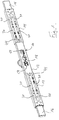
- the tank bolt illustrated in the figures comprises a tubular lock body 10 (FIG. Fig. 1 ), which is composed of a base body 12 having a substantially rectangular cross-section and two sliding tubes 14 which are fitted at both ends of the base body 12 form-fitting thereto, so that the sliding tubes 14 comprise the base body 12 outside and can be moved relative to this.
- the main body 12 and the sliding tubes 14 are provided on their rear side, not shown, in each case with bores, in particular oblong holes, for attachment to a door leaf. In this case, slots are advantageous in that they allow flexible positioning of the attachment points.
- each locking element 16 is slidably mounted in each end portion of the lock body 10.
- Each locking element 16 has a rectangular cross-section adapted to the base body 12, so that the locking element 16 is positively received in the base body 12 in the region of its inner end.
- the locking element 16 is guided at least in the region of the outer end of the associated sliding tube 14, for example by means arranged in the sliding tube 14 guide sleeve, which ensures optimum storage of the locking element 16 in the sliding tube 14 and thereby ultimately to a clean enclosure of the locking element sixteenth contributes.
- each locking element 16 is adapted to the inner cross section of the base body 12 and at the same time the inner cross section of each sliding tube 14 is adapted to the outer cross section of the base body 12, there is a gap between each locking element 16 and the associated sliding tube 14, which space for the heads of Creates screws for fixing the armor bolt on the door leaf.
- lock elements 16 By actuating a lock cylinder 18 received in the lock body 14, the lock elements 16 are moved from a retracted position (not shown) to an extended position (in FIG Fig. 1 shown) displaceable, in which their outer ends in each case in a lock box, not shown, which can be mounted on a door frame or masonry, can intervene.
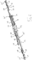
- each locking element 16 is coupled to a displaceably mounted in the lock body 10 drive rod 20 ( Fig. 2 ), which has a rack portion 22 which engages with a by the locking lug of the lock cylinder 18 driven gear, in such a way that an actuation of the lock cylinder 18 results in an opposite movement of the drive rods 20, whereby the locking elements 16 simultaneously on or be extended.
- a right locking element 16 (not shown) is coupled to the right end of the upper drive rod 20 ', indicated by a screw 26' threaded into a coupling piece 24 of the drive rod 20 ', while a left locking element 16 (not shown) on also indicated by a screw 26 "screwed into a coupling piece 24 of the drive rod 20.
- a right turn of the lock cylinder 18 in this case leads to an extension of the locking elements 16 and a left turn corresponding to a retraction. If a change in the closing direction is desired, only the right locking element 16 at the right end of the lower drive rod 20 "and the left locking element 16 at the left end of the upper drive rod 20 'needs to be coupled.
- Each drive rod 20 thus has at both ends in each case a coupling piece 24, wherein all coupling pieces 24 are constructed identically.
- each coupling piece 24 is formed in the form of a carriage, which in the area of his outer end of a threaded bore 28 for receiving the aforementioned screw 26 is formed, which serves to fasten a locking element 16.
- the threaded bore 28 forms a coupling point for the locking element 16.
- Both in the base body 12 and in the sliding tubes 14 are openings 30, in particular elongated holes formed ( Fig. 1 ), which provide access to the coupling points, so that the conversion of the closing direction by moving the screws 26 can be easily done at any time.
- each coupling piece 24 is slidably mounted on a rod portion 32, which emerges from a projection 34 at the end of the rack portion 22 of the respective drive rod 20 and forms a slide guide. Between the coupling piece 24 and the projection 34, a helical compression spring 36 surrounding the rod portion 32 is arranged, against the restoring force of which the coupling piece 24 moves in the direction of the toothed rack portion 22, i. so inward, can compress.
- a blocking element 38 is mounted pivotably in the form of a lever, which extends in the direction of projection 34.
- the blocking element 38 forms a link 40, which has an obliquely extending to the longitudinal extent of the drive rod 20 first link section 40 'and an adjoining, extending in the direction of the longitudinal extent of the drive rod 20 second link section 40 ".
- a sliding block 42 is guided ( Fig. 3 ), which is formed on the projection 34 and which limits the movement of the coupling piece 24 along the rod portion 32.
- the sliding block 42 In a rest position of the coupling piece 24, which defines an outermost position of the coupling piece 24, the sliding block 42 is located at the end of the oblique first slide portion 40 'and the locking element 38 is aligned with the drive rod 20, to allow a displacement of the drive rod 20 and thus of the coupled locking element 16 along the lock body 10.
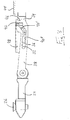
- the coupling piece 24 moves together with the locking element 16 against the helical compression spring 36 along the rod section 32 to the projection 34, whereby the sliding block 42 along the first slide section 40 'and optionally moved to the second gate section 40 "and the locking element 38 is pivoted into a blocking position in which it with a wall 44 of the lock body 10, in the illustrated embodiment with a wall 44 of the body 12, engage and against further displacement of the Coupling piece 24 and locking element 16 can lock Fig. 3 is shown, the blocking element 38 forms on its inwardly facing end face a mouth 46 for receiving the wall 44, to prevent inadvertent slippage on the wall 44 and to promote a claw in the wall 44.
- each drive rod 20 is fixed to the drive rod 20 by means of a screw 50 that can be displaced along the drive rod 20 ( Fig. 2 ).
- the striker 48 of the upper drive rod 20 'abuts a gearbox housing 52 of the armor latch and defines a first key removal position
- the striker 48 of the lower drive rod 20 "abuts the gearbox 52
- the desired key removal positions can be set, for example, when the lock cylinder 18 is replaced 54 formed in the base body 12 ( Fig. 4 ).
- abutment bodies 48 are arranged to the left of the transmission housing 52 in the illustrated embodiment, it will be understood that the abutment bodies 48 may in principle also be arranged to the right of the transmission housing 52. In addition, it is conceivable to arrange the abutment bodies 48 on opposite sides of the transmission housing 52 on either the upper or lower drive rod 20.
Landscapes
- Engineering & Computer Science (AREA)
- Mechanical Engineering (AREA)
- Power-Operated Mechanisms For Wings (AREA)
- Operating, Guiding And Securing Of Roll- Type Closing Members (AREA)
Abstract
Description
- Die Erfindung betrifft einen Panzerriegel mit einem rohrförmigen Schlosskörper, einem in dem Schlosskörper aufgenommenen Schließzylinder und zwei in entgegengesetzten Endabschnitten des Schlosskörpers verschiebbar gelagerten Riegelelementen, wobei jedes Riegelelement mit einer in dem Schlosskörper gelagerten Antriebsstange gekoppelt ist und die Antriebsstangen durch den Schließzylinder gegenläufig antreibbar sind, so dass die Riegelelemente bei einer Verdrehung des Schließzylinders in einer Schließrichtung aus einer eingefahrenen Stellung in eine ausgefahrene Stellung und bei einer Verdrehung des Schließzylinders entgegen der Schließrichtung aus der ausgefahrenen Stellung in die eingefahrene Stellung verschoben werden.
- Ein solcher Panzerriegel ist grundsätzlich bekannt und wird beispielsweise zur Erhöhung der Einbruchssicherheit derart an einem Türblatt montiert, dass er sich zumindest annähernd über die Breite des Türblatts erstreckt und die Riegelelemente in ihrer ausgefahrenen Stellung in Schließkästen eingreifen, die an der Türzarge und/oder am Mauerwerk verankert sind. Der bekannte Panzerriegel erweist sich insofern als nachteilig, als sich ein ausgefahrenes Riegelelement bei einem Einbruch gewaltsamen eindrücken lässt, weil der Schließzylinder nicht stark genug ist, um die Kraft aufzunehmen, die durch die zusammen mit dem Riegelelement zurückgedrückte Antriebsstange ausgeübt wird.
- Der Erfindung liegt die Aufgabe zugrunde, einen Panzerriegel zu schaffen, welcher sich durch eine verbesserte Einbruchssicherheit auszeichnet.
- Die Aufgabe wird durch einen Panzerriegel mit den Merkmalen des Anspruchs 1 und insbesondere dadurch gelöst, dass ein Sperrelement an jeder Antriebsstange ausgebildet ist, welches bei einem Eindrücken eines ausgefahrenen Riegelelements in eine Sperrstellung verlagert wird, in der es mit einer Wand des Schlosskörpers in Eingriff gerät, um zu verhindern, dass das Riegelelement seine eingefahrene Stellung erreichen kann.
- Der Erfindung liegt mit anderen Worten der allgemeine Gedanke zugrunde, ein zusätzliches Sperrelement vorzusehen, welches die bei einem gewaltsamen Eindrücken eines Riegelelements auftretenden Kräfte aufnimmt, indem es sich an einer Wand des Schlosskörpers abstützt. Sobald das Sperrelement mit der Wand des Schlosskörpers in Eingriff steht, ist das entsprechende Riegelelement blockiert und das Riegelelement kann nicht weiter aufgedrückt werden, wodurch die Einbruchssicherheit erheblich erhöht ist.
- Vorteilhafte Ausbildungen der Erfindung sind den Unteransprüchen, der Beschreibung und der Zeichnung zu entnehmen.
- Um ein Vorbeirutschen des Sperrelements an der Wand zu verhindern und eine Verkrallung in der Wand zu begünstigen, bildet das Sperrelement bevorzugt ein Maul zur Aufnahme der Wand aus.
- Gemäß einer Ausführungsform handelt es sich bei dem Sperrelement um einen an der Antriebsstange verschwenkbar angebrachten Hebel, welcher in der Sperrstellung aus einer durch die Antriebsstangen definierten Ebene herausragt.
- Bevorzugt ist das Sperrelement an einem Schlitten der Antriebsstange angebracht, welcher zur Ankopplung eines Riegelelements dient und welcher in Richtung des Schließzylinders entgegen der Rückstellkraft einer Feder, insbesondere einer Schraubendruckfeder, entlang einer Schlittenführung der Antriebsstange verschiebbar ist.
- Außerdem kann eine Kulissenführung zur Verschwenkung des Sperrelements vorgesehen sein. Vorteilhafterweise umfasst die Kulissenführung eine in dem Sperrelement ausgebildete Kulisse und einen Kulissenstein, welcher relativ zu dem Sperrelement feststehend an der Antriebsstange ausgebildet ist und in die Kulisse eingreift. Die Kulisse weist bevorzugt einen ersten Abschnitt, der sich schräg zur Längsrichtung der Antriebsstange erstreckt, und einen zweiten Abschnitt auf, der sich in Längsrichtung der Antriebsstange erstreckt.
- Gemäß einer weiteren Ausführungsform weist der Schlosskörper einen Grundkörper und zwei Schieberohre auf, welche gegenüberliegende Endabschnitte des Grundkörpers außen umfassen und relativ zu dem Grundkörper verschiebbar sind. Der Schlosskörper ist mit anderen Worten teleskopierbar ausgebildet, wodurch sich die Länge des Schlosskörpers auf einfache Weise an unterschiedliche Türblattbreiten anpassen lässt. Es brauchen also keine unterschiedlichen Längen von Schlosskörpern hergestellt und vorgehalten zu werden, sondern der Panzerriegel lässt sich individuell und exakt auf die jeweils vorliegende Breite des Türblatts einstellen. Wird der Schlosskörper so eingestellt, dass er sich über die gesamte Breite des Türblatts erstreckt, wird außerdem das Türblatt optimal abgestützt und stabilisiert, was letztlich der Einbruchssicherheit zugutekommt. Hierzu trägt auch bei, dass durch das Aufstecken der Schieberohre auf den Grundkörper zusätzlicher Platz für eine Verschraubung der Schieberohre mit dem Türblatt in den Schieberohren geschaffen wird, nämlich eine Spaltbreite, die der Stärke der Wand des Grundkörpers entspricht. In diesem Spalt können Schraubenköpfe unterhalb des Riegelelements angeordnet werden. Durch die Verschiebbarkeit der Schieberohre können zudem optimale Punkte für die Verschraubung an dem Türblatt gewählt werden.
- Vorteilhafterweise umfassen die Schieberohre den Grundkörper jeweils formschlüssig, d.h. die Schieberohre sind passgenau auf den Grundkörper aufgesteckt, was zur Stabilität des Panzerriegels beiträgt.
- Zur Erleichterung der Montage des Panzerriegels sind der Grundkörper und die Schieberohre vorteilhafterweise jeweils mit Bohrungen, insbesondere Langlöchern, zur Befestigung an einem Türblatt versehen.
- Gemäß einer weiteren Ausführungsform ist jedes Riegelelement in einem Schieberohr geführt. Zur Führung des Riegelelements in dem jeweiligen Schieberohr kann eine Manschette in dem Schieberohr angeordnet sein, welche für einen optimierten Sitz des Riegelelements in dem Schieberohr sorgt. Auf diese Weise ist sichergestellt, dass die Riegelelemente in Bezug auf Biegesteifigkeit optimal geführt sind.
- Die Riegelelemente lassen sich auf besonders einfache Weise verfahren, wenn jede Antriebsstange einen Zahnstangenabschnitt aufweist, welcher mit einem durch den Schließzylinder antreibbaren Zahnrad in Eingriff steht.
- Bevorzugt weist jede Antriebsstange an beiden Enden jeweils eine Kopplungsstelle zur Ankopplung eines Riegelelements auf. Je nachdem an welchem Ende der
- Antriebsstangen die Riegelelemente angebunden sind, lassen sich die Riegelelemente durch Links- oder Rechtsdrehung des Schließzylinders ausfahren bzw. umgekehrt durch Rechts- oder Linksdrehung einfahren. Hierdurch kann auf einfache Weise die Schließrichtung des Panzerriegels umgestellt werden.
- Bevorzugt sind die Antriebsstangen identisch ausgebildet, weil sich der Panzerriegel hierdurch noch kostengünstiger herstellen lässt.
- Gemäß einer weiteren Ausführungsform ist wenigstens ein Anschlagskörper zur Einstellung einer Schlüsselabziehstellung auf einer Antriebsstange verstellbar gelagert. Bevorzugt sind zwei Anschlagskörper vorgesehen, einer zur Einstellung der Schlüsselabziehstellung bei eingefahrenen Riegelelementen und einer zur Einstellung der Schlüsselabziehstellung bei ausgefahrenen Riegelelementen. Dabei kann jede Antriebsstange mit einem Anschlagskörper versehen sein, wobei in diesem Fall die Anschlagskörper entweder auf der einen Seite des Schließzylinders oder auf der anderen Seite des Schließzylinders angeordnet sein können. Alternativ ist es auch denkbar, eine der Antriebsstangen mit zwei Anschlagskörpern zu versehen, welche in diesem Fall auf gegenüberliegenden Seiten des Schließzylinders anzuordnen wären. Vorteilhafterweise ist wenigstens ein Fenster in dem Schlosskörper ausgebildet, welches von außen Zugang zu den Anschlagskörpern gewährt, so dass sich die Anschlagskörper beispielsweise nach einem Austausch des Schließzylinders auch bei montiertem Panzerriegel leicht in der gewünschten Position fixieren und die Schlüsselabziehstellungen optimal einstellen lassen. Mit den Anschlagskörpern können auch Schlüsselabziehstellungen für ein eintouriges Schließen eingestellt werden. Zu diesem Zweck werden die Anschlagskörper jeweils in einem mittleren Bereich der Zahnstangen positioniert und befestigt.
- Nachfolgend wird die Erfindung rein beispielhaft anhand einer möglichen Ausführungsform unter Bezugnahme auf die beigefügte Zeichnung beschrieben.
- Fig. 1
- zeigt einen erfindungsgemäßen Panzerriegel mit ausgefahrenen Riegelelementen.
- Fig. 2
- zeigt Teile der Antriebsmechanik des Panzerriegels von
Fig. 1 . - Fig. 3
- zeigt eine Vergrößerung einer Kopplungsstelle einer Antriebsstange des Panzerriegels von
Fig. 1 . - Fig. 4
- zeigt eine Vergrößerung eines zentralen Bereichs des Panzerriegels von
Fig. 1 . - Der in den Figuren dargestellte Panzerriegel umfasst einen rohrförmigen Schlosskörper 10 (
Fig. 1 ), welcher sich aus einem Grundkörper 12 mit im Wesentlichen rechtwinkligen Querschnitt und zwei Schieberohren 14 zusammensetzt, welche an beiden Enden des Grundkörpers 12 formschlüssig auf diesen aufgesteckt sind, so dass die Schieberohre 14 den Grundkörper 12 außen umfassen und sich relativ zu diesem verschieben lassen. Der Grundkörper 12 und die Schieberohre 14 sind an ihrer nicht dargestellten Rückseite jeweils mit Bohrungen, insbesondere Langlöchern, zur Befestigung an einem Türblatt versehen. Dabei sind Langlöcher insofern vorteilhaft, als sie eine flexible Positionierung der Befestigungspunkte ermöglichen. - In jedem Endabschnitt des Schlosskörpers 10 ist ein Riegelelement 16 verschiebbar gelagert. Jedes Riegelelement 16 weist einen an den Grundkörper 12 anpassten rechtwinkligen Querschnitt auf, so dass das Riegelelement 16 im Bereich seines innen liegenden Endes formschlüssig in dem Grundkörper 12 aufgenommenen ist. Zusätzlich ist das Riegelelement 16 wenigstens im Bereich des äußeren Endes des zugeordneten Schieberohrs 14 geführt, beispielsweise mittels einer in dem Schieberohr 14 angeordneten Führungsmanschette, welche für eine optimale Lagerung des Riegelelements 16 in dem Schieberohr 14 sorgt und dadurch letztlich zu einem sauberen Einschließen des Riegelelements 16 beiträgt. Da der Außenquerschnitt jedes Riegelelements 16 an den Innenquerschnitt des Grundkörpers 12 angepasst ist und gleichzeitig der Innenquerschnitt jedes Schieberohrs 14 an den Außenquerschnitt des Grundkörpers 12 angepasst ist, liegt ein Spalt zwischen jedem Riegelelement 16 und dem zugeordneten Schieberohr 14 vor, welcher Platz für die Köpfe von Schrauben zur Befestigung des Panzerriegels an dem Türblatt schafft.
- Durch Betätigung eines in dem Schlosskörper 14 aufgenommenen Schließzylinders 18 sind die Riegelelemente 16 aus einer eingefahrenen Stellung (nicht gezeigt) in eine ausgefahrene Stellung (in
Fig. 1 dargestellt) verschiebbar, in welcher ihre äußeren Enden jeweils in einen nicht dargestellten Schließkasten, der an einer Türzarge oder einem Mauerwerk montiert sein kann, eingreifen können. - Hierzu ist jedes Riegelelement 16 mit einer in dem Schlosskörper 10 verschiebbar gelagerten Antriebsstange 20 gekoppelt (
Fig. 2 ), welche einen Zahnstangenabschnitt 22 aufweist, der mit einem durch die Schließnase des Schließzylinders 18 antreibbaren Zahnrad in Eingriff steht, und zwar derart, dass eine Betätigung des Schließzylinders 18 in einer gegenläufigen Bewegung der Antriebsstangen 20 resultiert, wodurch die Riegelelemente 16 gleichzeitig ein- oder ausgefahren werden. - Bei dem hier dargestellten Ausführungsbeispiel ist ein rechtes Riegelelement 16 (nicht gezeigt) am rechten Ende der oberen Antriebsstange 20' angekoppelt, angedeutet durch eine in ein Kopplungsstück 24 der Antriebsstange 20' eingeschraubte Schraube 26', während ein linkes Riegelelement 16 (nicht gezeigt) am linken Ende der unteren Antriebsstange 20" angekoppelt ist, ebenfalls angedeutet durch eine in ein Kopplungsstück 24 der Antriebsstange 20" eingeschraubte Schraube 26". Eine Rechtsdrehung des Schließzylinders 18 führt in diesem Fall zu einem Ausfahren der Riegelelemente 16 und eine Linksdrehung entsprechend zu einem Einfahren. Wird eine Umstellung der Schließrichtung gewünscht, braucht lediglich das rechte Riegelelement 16 am rechten Ende der unteren Antriebsstange 20" und das linke Riegelelement 16 am linken Ende der oberen Antriebsstange 20' angekoppelt zu werden.
- Jede Antriebsstange 20 weist also an beiden Enden jeweils ein Kopplungsstück 24 auf, wobei alle Kopplungsstücke 24 identisch aufgebaut sind. Konkret ist jedes Kopplungsstück 24 in Form eines Schlittens ausgebildet, welcher im Bereich seines äußeren Endes eine Gewindebohrung 28 zur Aufnahme der bereits erwähnten Schraube 26 ausbildet, die zur Befestigung eines Riegelelements 16 dient. Die Gewindebohrung 28 bildet mit anderen Worten also eine Kopplungsstelle für das Riegelelement 16. Sowohl in dem Grundkörper 12 als auch in den Schieberohren 14 sind Öffnungen 30, insbesondere Langlöcher, ausgebildet (
Fig. 1 ), welche Zugang zu den Kopplungsstellen gewähren, so dass sich die Umstellung der Schließrichtung durch Umsetzen der Schrauben 26 jederzeit leicht vollziehen lässt. - Außerdem ist jedes Kopplungsstück 24 auf einem Stangenabschnitt 32 verschiebbar gelagert, welcher aus einem Ansatz 34 am Ende des Zahnstangenabschnitts 22 der jeweiligen Antriebsstange 20 hervorgeht und eine Schlittenführung bildet. Zwischen dem Kopplungsstück 24 und dem Ansatz 34 ist eine den Stangenabschnitt 32 umgebende Schraubendruckfeder 36 angeordnet, entgegen deren Rückstellkraft das Kopplungsstück 24 in Richtung Zahnstangenabschnitt 22, d.h. also nach innen, einfedern kann.
- An dem Kopplungsstück 24 ist ein Sperrelement 38 in Form eines Hebels verschwenkbar angebracht, welches sich in Richtung Ansatz 34 erstreckt. Das Sperrelement 38 bildet eine Kulisse 40 aus, die einen schräg zur Längserstreckung der Antriebsstange 20 verlaufenden ersten Kulissenabschnitt 40' und einen sich daran anschließenden, in Richtung der Längserstreckung der Antriebsstange 20 verlaufenden zweiten Kulissenabschnitt 40" aufweist.
- In der Kulisse 40 des Sperrelements 38 ist ein Kulissenstein 42 geführt (
Fig. 3 ), welcher an dem Ansatz 34 ausgebildet ist und welcher die Bewegung des Kopplungsstücks 24 entlang des Stangenabschnitts 32 begrenzt. In einer Ruhelage des Kopplungsstücks 24, welche eine äußerste Position des Kopplungsstücks 24 definiert, befindet sich der Kulissenstein 42 am Ende des schrägen ersten Kulissenabschnitts 40' und das Sperrelement 38 ist mit der Antriebsstange 20 ausgerichtet, um eine Verschiebung der Antriebsstange 20 und somit des angekoppelten Riegelelements 16 entlang des Schlosskörpers 10 zu ermöglichen. - Wird das ausgefahrene Riegelelement 16 beispielsweise bei einem Einbruchsversuch gewaltsam eingedrückt, so bewegt sich das Kopplungsstück 24 zusammen mit dem Riegelelement 16 entgegen der Schraubendruckfeder 36 entlang des Stangenabschnitts 32 auf den Ansatz 34 zu, wodurch sich der Kulissenstein 42 entlang des ersten Kulissenabschnitts 40' und gegebenenfalls bis in den zweiten Kulissenabschnitt 40" bewegt und das Sperrelement 38 in eine Sperrstellung verschwenkt wird, in welcher es mit einer Wand 44 des Schlosskörpers 10, bei dem dargestellten Ausführungsbeispiel mit einer Wand 44 des Grundkörpers 12, in Eingriff treten und gegen eine weitergehende Verschiebung des Kopplungsstücks 24 und Riegelelements 16 sperren kann. Wie in
Fig. 3 dargestellt ist, bildet das Sperrelement 38 an seiner nach innen weisenden Stirnseite ein Maul 46 zur Aufnahme der Wand 44 aus, um ein unbeabsichtigtes Vorbeirutschen an der Wand 44 zu verhindern und eine Verkrallung in der Wand 44 zu begünstigen. - Ferner ist im Bereich des linken Ansatzes 34 jeder Antriebsstange 20 ein entlang der Antriebsstange 20 verschiebbarer Anschlagskörper 48 mittels einer Schraube 50 an der Antriebsstange 20 fixiert (
Fig. 2 ). In dem dargestellten ausgefahrenen Zustand der Riegelelemente 16 schlägt der Anschlagskörper 48 der oberen Antriebsstange 20' an einem Getriebegehäuse 52 des Panzerriegels an und definiert eine erste Schlüsselabziehstellung, wohingegen im eingefahrenen Zustand der Riegelelemente 16 der Anschlagskörper 48 der unteren Antriebsstange 20" an das Getriebegehäuse 52 anschlägt und eine zweite Schlüsselabziehstellung definiert. Durch geeignete Positionierung der Anschlagskörper 48 lassen sich also die gewünschten Schlüsselabziehstellungen einstellen, beispielsweise bei einem Austausch des Schließzylinders 18. Damit die Anschlagskörper 48 auch nach der Montage des Panzerriegels von außen zugänglich sind und verstellt werden können, sind entsprechende Fenster 54 in dem Grundkörper 12 ausgebildet (Fig. 4 ). Obwohl die Anschlagskörper 48 im dargestellten Ausführungsbeispiel links von dem Getriebegehäuse 52 angeordnet sind, versteht es sich, dass die Anschlagskörper 48 grundsätzlich auch rechts von dem Getriebegehäuse 52 angeordnet sein können. Außerdem ist es vorstellbar, die Anschlagskörper 48 auf gegenüberliegenden Seiten des Getriebegehäuses 52 an entweder der oberen oder der unteren Antriebsstange 20 anzuordnen. -
- 10
- Schlosskörper
- 12
- Grundkörper
- 14
- Schieberohr
- 16
- Riegelelement
- 18
- Schließzylinder
- 20
- Antriebsstange
- 22
- Zahnstangenabschnitt
- 24
- Kopplungsstück
- 26
- Schraube
- 28
- Gewindebohrung
- 30
- Öffnung
- 32
- Stangenabschnitt
- 34
- Ansatz
- 36
- Schraubendruckfeder
- 38
- Sperrelement
- 40
- Kulisse
- 40'
- erster Kulissenabschnitt
- 40"
- zweiter Kulissenabschnitt
- 42
- Kulissenstein
- 44
- Wand
- 46
- Maul
- 48
- Anschlagskörper
- 50
- Schraube
- 52
- Getriebegehäuse
- 54
- Fenster
Claims (15)
- Panzerriegel mit einem rohrförmigen Schlosskörper (10), einem in dem Schlosskörper (10) aufgenommenen Schließzylinder (18) und zwei in entgegengesetzten Endabschnitten des Schlosskörpers (10) verschiebbar gelagerten Riegelelementen (16), wobei jedes Riegelelement (16) mit einer in dem Schlosskörper (10) gelagerten Antriebsstange (20) gekoppelt ist und die Antriebsstangen durch den Schließzylinder (18) gegenläufig antreibbar sind, so dass die Riegelelemente (16) bei einer Verdrehung des Schließzylinders (18) in einer Schließrichtung aus einer eingefahrenen Stellung in eine ausgefahrene Stellung und bei einer Verdrehung des Schließzylinders (18) entgegen der Schließrichtung aus der ausgefahrenen Stellung in die eingefahrene Stellung verschoben werden,
dadurch gekennzeichnet, dass
ein Sperrelement (38) an jeder Antriebsstange (20) ausgebildet ist, welches bei einem Eindrücken eines ausgefahrenen Riegelelements (16) in eine Sperrstellung verlagert wird, in welcher es mit einer Wand (44) des Schlosskörpers (10) in Eingriff gerät, um zu verhindern, dass das Riegelelement (16) seine eingefahrene Stellung erreichen kann. - Panzerriegel nach Anspruch 1,
dadurch gekennzeichnet, dass
das Sperrelement (38) ein an der Antriebsstange (20) verschwenkbar angebrachter Hebel ist, welcher in der Sperrstellung aus einer durch die Antriebsstangen (20) definierten Ebene herausragt. - Panzerriegel nach Anspruch 1 oder 2,
dadurch gekennzeichnet, dass
das Sperrelement (38) an einem Schlitten der Antriebsstange (20) angebracht ist, welcher zur Ankopplung eines Riegelelements (16) dient und welcher in Richtung des Schließzylinders entgegen der Rückstellkraft einer Feder, insbesondere einer Schraubendruckfeder (36), entlang einer Schlittenführung der Antriebsstange (20) verschiebbar ist. - Panzerriegel nach zumindest einem der vorherigen Ansprüche,
dadurch gekennzeichnet, dass
eine Kulissenführung zur Verschwenkung des Sperrelements (38) vorgesehen ist. - Panzerriegel nach Anspruch 4,
dadurch gekennzeichnet, dass
die Kulissenführung eine in dem Sperrelement (38) ausgebildete Kulisse (40) und einen Kulissenstein umfasst, welcher relativ zu dem Sperrelement (38) feststehend an der Antriebsstange (20) ausgebildet ist und in die Kulisse eingreift. - Panzerriegel nach Anspruch 5,
dadurch gekennzeichnet, dass
die Kulisse (40) einen ersten Abschnitt (40'), der sich schräg zur Längsrichtung der Antriebsstange (20) erstreckt, und einen zweiten Abschnitt (40") aufweist, der sich in Längsrichtung der Antriebsstange (20) erstreckt. - Panzerriegel nach zumindest einem der vorherigen Ansprüche,
dadurch gekennzeichnet, dass der Schlosskörper (10) einen Grundkörper und zwei Schieberohre (14) aufweist, welche gegenüberliegende Endabschnitte des Grundkörpers (12) außen umfassen und relativ zu dem Grundkörper (12) verschiebbar sind. - Panzerriegel nach Anspruch 7,
dadurch gekennzeichnet, dass
die Schieberohre (14) den Grundkörper (12) jeweils formschlüssig umfassen. - Panzerriegel nach Anspruch 7 oder 8,
dadurch gekennzeichnet, dass
der Grundkörper (12) und die Schieberohre (14) jeweils mit Bohrungen, insbesondere Langlöchern, zur Befestigung an einem Türblatt versehen sind. - Panzerriegel nach zumindest einem der vorherigen Ansprüche,
dadurch gekennzeichnet, dass
das jedes Riegelelement (16) in einem Schieberohr (14) geführt ist. - Panzerriegel nach zumindest einem der vorherigen Ansprüche,
dadurch gekennzeichnet, dass
jede Antriebsstange (20) einen Zahnstangenabschnitt (22) aufweist, welcher mit einem durch den Schließzylinder (18) antreibbaren Zahnrad in Eingriff steht. - Panzerriegel nach zumindest einem der vorherigen Ansprüche,
dadurch gekennzeichnet, dass
jede Antriebsstange (20) an beiden Enden jeweils eine Kopplungsstelle zur Ankopplung eines Riegelelements (16) aufweist. - Panzerriegel nach zumindest einem der vorherigen Ansprüche,
dadurch gekennzeichnet, dass
wenigstens ein Anschlagskörper (48) zur Einstellung einer Schlüsselabziehstellung auf einer Antriebsstange (20) verstellbar gelagert ist. - Panzerriegel nach Anspruch 13,
dadurch gekennzeichnet, dass
wenigstens ein Fenster (54) in dem Schlosskörper (10) ausgebildet ist, welches von außen Zugang zu den Anschlagskörpern (48) gewährt. - Panzerriegel nach zumindest einem der vorherigen Ansprüche,
dadurch gekennzeichnet, dass
das Sperrelement (38) ein Maul (46) zur Aufnahme der Wand (44) ausbildet.
Applications Claiming Priority (1)
| Application Number | Priority Date | Filing Date | Title |
|---|---|---|---|
| DE102016114387.1A DE102016114387A1 (de) | 2016-08-03 | 2016-08-03 | Panzerriegel |
Publications (2)
| Publication Number | Publication Date |
|---|---|
| EP3279414A1 true EP3279414A1 (de) | 2018-02-07 |
| EP3279414B1 EP3279414B1 (de) | 2019-09-18 |
Family
ID=59485237
Family Applications (1)
| Application Number | Title | Priority Date | Filing Date |
|---|---|---|---|
| EP17183671.1A Active EP3279414B1 (de) | 2016-08-03 | 2017-07-28 | Panzerriegel |
Country Status (3)
| Country | Link |
|---|---|
| EP (1) | EP3279414B1 (de) |
| DE (1) | DE102016114387A1 (de) |
| ES (1) | ES2761313T3 (de) |
Families Citing this family (1)
| Publication number | Priority date | Publication date | Assignee | Title |
|---|---|---|---|---|
| GB202002015D0 (en) * | 2020-02-13 | 2020-04-01 | Locks4Vans Ltd | A lock assembly for a vehicle load compartment |
Citations (5)
| Publication number | Priority date | Publication date | Assignee | Title |
|---|---|---|---|---|
| DE2649421A1 (de) * | 1975-12-01 | 1977-06-08 | Viro Innocenti Spa | Sicherheitsschloss |
| US5010747A (en) * | 1990-02-05 | 1991-04-30 | Norden Jr H Peter | Secur a door police lock |
| US5709111A (en) * | 1995-12-04 | 1998-01-20 | Henao; Jose Gabriel | Lock system |
| WO2001090517A1 (en) * | 2000-05-23 | 2001-11-29 | Invicta Sicurezza Di Poli Sergio E Colombarini Giorgio & C. S.N.C. | Improved modular burglar bars |
| US20070084258A1 (en) * | 2003-03-19 | 2007-04-19 | Mul-T-Lock Technologies Ltd. | Enhanced extendable multipoint lock |
-
2016
- 2016-08-03 DE DE102016114387.1A patent/DE102016114387A1/de active Pending
-
2017
- 2017-07-28 ES ES17183671T patent/ES2761313T3/es active Active
- 2017-07-28 EP EP17183671.1A patent/EP3279414B1/de active Active
Patent Citations (5)
| Publication number | Priority date | Publication date | Assignee | Title |
|---|---|---|---|---|
| DE2649421A1 (de) * | 1975-12-01 | 1977-06-08 | Viro Innocenti Spa | Sicherheitsschloss |
| US5010747A (en) * | 1990-02-05 | 1991-04-30 | Norden Jr H Peter | Secur a door police lock |
| US5709111A (en) * | 1995-12-04 | 1998-01-20 | Henao; Jose Gabriel | Lock system |
| WO2001090517A1 (en) * | 2000-05-23 | 2001-11-29 | Invicta Sicurezza Di Poli Sergio E Colombarini Giorgio & C. S.N.C. | Improved modular burglar bars |
| US20070084258A1 (en) * | 2003-03-19 | 2007-04-19 | Mul-T-Lock Technologies Ltd. | Enhanced extendable multipoint lock |
Also Published As
| Publication number | Publication date |
|---|---|
| DE102016114387A1 (de) | 2018-02-08 |
| EP3279414B1 (de) | 2019-09-18 |
| ES2761313T3 (es) | 2020-05-19 |
Similar Documents
| Publication | Publication Date | Title |
|---|---|---|
| DE3310020C2 (de) | ||
| EP3266967B1 (de) | Stangenschloss | |
| WO1991017334A1 (de) | Mit zylinderschlosseinrichtung arretierbarer schwenkhebelverschluss | |
| EP1900891A2 (de) | Klapp-Hebelverschluss | |
| EP0440987B2 (de) | Treibstangengetriebe | |
| EP3279415B1 (de) | Panzerriegel | |
| DE202007004845U1 (de) | Teleskopansatz für Rolladenachse | |
| EP0433623A2 (de) | Verriegelungsvorrichtung für ein Fenster, eine Tür od.dgl. | |
| EP3279414B1 (de) | Panzerriegel | |
| DE102015000606A1 (de) | Verriegelungsvorrichtung für einen schwenkbar gelagerten Flügel | |
| DE29509503U1 (de) | Mehrfachverriegelungsanlage | |
| EP3018269B1 (de) | Griffanordnung für ein fenster oder dergleichen sowie fenster oder dergleichen mit griffanordnung | |
| EP2085543B1 (de) | Schloss | |
| DE2340580A1 (de) | Einsteckschloss, insbesondere fuer rohrrahmentueren | |
| DE3221110A1 (de) | Beschlag fuer einen kipp- und nachfolgend mindestens parallelabstellbaren fluegel eines fensters, einer tuer od. dgl. | |
| EP3913171A1 (de) | Verriegelungs- und/oder positionierantrieb für ein fenster, eine tür oder dergleichen | |
| EP2221435B1 (de) | Fensterzusatzsicherung | |
| EP0913546B1 (de) | Getriebebeschlag für einen Flügelrahmen | |
| EP2481872A2 (de) | Verriegelungsanordnung für Fenster, Türen oder dergleichen mit einem Schwenkriegel | |
| DE9104766U1 (de) | Antipaniktürschloß | |
| WO1993004253A1 (de) | Sicherheitstür und sicherheitsvorrichtung zum einbau in eine tür | |
| EP2719850B1 (de) | Einsteckschloss | |
| EP1455041B1 (de) | Mehrriegelschloss mit Schubstange und mit einer Haltevorrichtung | |
| EP1270856B1 (de) | Beschlag für die Verriegelung von Fenstern oder Türen | |
| DE1908478A1 (de) | Treibstangenverbindung |
Legal Events
| Date | Code | Title | Description |
|---|---|---|---|
| PUAI | Public reference made under article 153(3) epc to a published international application that has entered the european phase |
Free format text: ORIGINAL CODE: 0009012 |
|
| STAA | Information on the status of an ep patent application or granted ep patent |
Free format text: STATUS: THE APPLICATION HAS BEEN PUBLISHED |
|
| AK | Designated contracting states |
Kind code of ref document: A1 Designated state(s): AL AT BE BG CH CY CZ DE DK EE ES FI FR GB GR HR HU IE IS IT LI LT LU LV MC MK MT NL NO PL PT RO RS SE SI SK SM TR |
|
| AX | Request for extension of the european patent |
Extension state: BA ME |
|
| STAA | Information on the status of an ep patent application or granted ep patent |
Free format text: STATUS: REQUEST FOR EXAMINATION WAS MADE |
|
| 17P | Request for examination filed |
Effective date: 20180806 |
|
| RBV | Designated contracting states (corrected) |
Designated state(s): AL AT BE BG CH CY CZ DE DK EE ES FI FR GB GR HR HU IE IS IT LI LT LU LV MC MK MT NL NO PL PT RO RS SE SI SK SM TR |
|
| GRAP | Despatch of communication of intention to grant a patent |
Free format text: ORIGINAL CODE: EPIDOSNIGR1 |
|
| STAA | Information on the status of an ep patent application or granted ep patent |
Free format text: STATUS: GRANT OF PATENT IS INTENDED |
|
| INTG | Intention to grant announced |
Effective date: 20190412 |
|
| GRAS | Grant fee paid |
Free format text: ORIGINAL CODE: EPIDOSNIGR3 |
|
| GRAA | (expected) grant |
Free format text: ORIGINAL CODE: 0009210 |
|
| STAA | Information on the status of an ep patent application or granted ep patent |
Free format text: STATUS: THE PATENT HAS BEEN GRANTED |
|
| AK | Designated contracting states |
Kind code of ref document: B1 Designated state(s): AL AT BE BG CH CY CZ DE DK EE ES FI FR GB GR HR HU IE IS IT LI LT LU LV MC MK MT NL NO PL PT RO RS SE SI SK SM TR |
|
| REG | Reference to a national code |
Ref country code: GB Ref legal event code: FG4D Free format text: NOT ENGLISH |
|
| REG | Reference to a national code |
Ref country code: CH Ref legal event code: EP |
|
| REG | Reference to a national code |
Ref country code: DE Ref legal event code: R096 Ref document number: 502017002329 Country of ref document: DE |
|
| REG | Reference to a national code |
Ref country code: AT Ref legal event code: REF Ref document number: 1181493 Country of ref document: AT Kind code of ref document: T Effective date: 20191015 |
|
| REG | Reference to a national code |
Ref country code: IE Ref legal event code: FG4D Free format text: LANGUAGE OF EP DOCUMENT: GERMAN |
|
| REG | Reference to a national code |
Ref country code: CH Ref legal event code: NV Representative=s name: DR. GRAF AND PARTNER AG INTELLECTUAL PROPERTY, CH |
|
| REG | Reference to a national code |
Ref country code: NL Ref legal event code: FP |
|
| PG25 | Lapsed in a contracting state [announced via postgrant information from national office to epo] |
Ref country code: FI Free format text: LAPSE BECAUSE OF FAILURE TO SUBMIT A TRANSLATION OF THE DESCRIPTION OR TO PAY THE FEE WITHIN THE PRESCRIBED TIME-LIMIT Effective date: 20190918 Ref country code: NO Free format text: LAPSE BECAUSE OF FAILURE TO SUBMIT A TRANSLATION OF THE DESCRIPTION OR TO PAY THE FEE WITHIN THE PRESCRIBED TIME-LIMIT Effective date: 20191218 Ref country code: SE Free format text: LAPSE BECAUSE OF FAILURE TO SUBMIT A TRANSLATION OF THE DESCRIPTION OR TO PAY THE FEE WITHIN THE PRESCRIBED TIME-LIMIT Effective date: 20190918 Ref country code: BG Free format text: LAPSE BECAUSE OF FAILURE TO SUBMIT A TRANSLATION OF THE DESCRIPTION OR TO PAY THE FEE WITHIN THE PRESCRIBED TIME-LIMIT Effective date: 20191218 Ref country code: HR Free format text: LAPSE BECAUSE OF FAILURE TO SUBMIT A TRANSLATION OF THE DESCRIPTION OR TO PAY THE FEE WITHIN THE PRESCRIBED TIME-LIMIT Effective date: 20190918 Ref country code: LT Free format text: LAPSE BECAUSE OF FAILURE TO SUBMIT A TRANSLATION OF THE DESCRIPTION OR TO PAY THE FEE WITHIN THE PRESCRIBED TIME-LIMIT Effective date: 20190918 |
|
| REG | Reference to a national code |
Ref country code: LT Ref legal event code: MG4D |
|
| PG25 | Lapsed in a contracting state [announced via postgrant information from national office to epo] |
Ref country code: AL Free format text: LAPSE BECAUSE OF FAILURE TO SUBMIT A TRANSLATION OF THE DESCRIPTION OR TO PAY THE FEE WITHIN THE PRESCRIBED TIME-LIMIT Effective date: 20190918 Ref country code: LV Free format text: LAPSE BECAUSE OF FAILURE TO SUBMIT A TRANSLATION OF THE DESCRIPTION OR TO PAY THE FEE WITHIN THE PRESCRIBED TIME-LIMIT Effective date: 20190918 Ref country code: RS Free format text: LAPSE BECAUSE OF FAILURE TO SUBMIT A TRANSLATION OF THE DESCRIPTION OR TO PAY THE FEE WITHIN THE PRESCRIBED TIME-LIMIT Effective date: 20190918 |
|
| PG25 | Lapsed in a contracting state [announced via postgrant information from national office to epo] |
Ref country code: EE Free format text: LAPSE BECAUSE OF FAILURE TO SUBMIT A TRANSLATION OF THE DESCRIPTION OR TO PAY THE FEE WITHIN THE PRESCRIBED TIME-LIMIT Effective date: 20190918 Ref country code: RO Free format text: LAPSE BECAUSE OF FAILURE TO SUBMIT A TRANSLATION OF THE DESCRIPTION OR TO PAY THE FEE WITHIN THE PRESCRIBED TIME-LIMIT Effective date: 20190918 Ref country code: IT Free format text: LAPSE BECAUSE OF FAILURE TO SUBMIT A TRANSLATION OF THE DESCRIPTION OR TO PAY THE FEE WITHIN THE PRESCRIBED TIME-LIMIT Effective date: 20190918 Ref country code: PL Free format text: LAPSE BECAUSE OF FAILURE TO SUBMIT A TRANSLATION OF THE DESCRIPTION OR TO PAY THE FEE WITHIN THE PRESCRIBED TIME-LIMIT Effective date: 20190918 Ref country code: PT Free format text: LAPSE BECAUSE OF FAILURE TO SUBMIT A TRANSLATION OF THE DESCRIPTION OR TO PAY THE FEE WITHIN THE PRESCRIBED TIME-LIMIT Effective date: 20200120 |
|
| REG | Reference to a national code |
Ref country code: ES Ref legal event code: FG2A Ref document number: 2761313 Country of ref document: ES Kind code of ref document: T3 Effective date: 20200519 |
|
| PG25 | Lapsed in a contracting state [announced via postgrant information from national office to epo] |
Ref country code: SK Free format text: LAPSE BECAUSE OF FAILURE TO SUBMIT A TRANSLATION OF THE DESCRIPTION OR TO PAY THE FEE WITHIN THE PRESCRIBED TIME-LIMIT Effective date: 20190918 Ref country code: IS Free format text: LAPSE BECAUSE OF FAILURE TO SUBMIT A TRANSLATION OF THE DESCRIPTION OR TO PAY THE FEE WITHIN THE PRESCRIBED TIME-LIMIT Effective date: 20200224 Ref country code: CZ Free format text: LAPSE BECAUSE OF FAILURE TO SUBMIT A TRANSLATION OF THE DESCRIPTION OR TO PAY THE FEE WITHIN THE PRESCRIBED TIME-LIMIT Effective date: 20190918 Ref country code: SM Free format text: LAPSE BECAUSE OF FAILURE TO SUBMIT A TRANSLATION OF THE DESCRIPTION OR TO PAY THE FEE WITHIN THE PRESCRIBED TIME-LIMIT Effective date: 20190918 |
|
| REG | Reference to a national code |
Ref country code: DE Ref legal event code: R097 Ref document number: 502017002329 Country of ref document: DE |
|
| PLBE | No opposition filed within time limit |
Free format text: ORIGINAL CODE: 0009261 |
|
| STAA | Information on the status of an ep patent application or granted ep patent |
Free format text: STATUS: NO OPPOSITION FILED WITHIN TIME LIMIT |
|
| PG2D | Information on lapse in contracting state deleted |
Ref country code: IS |
|
| PG25 | Lapsed in a contracting state [announced via postgrant information from national office to epo] |
Ref country code: IS Free format text: LAPSE BECAUSE OF FAILURE TO SUBMIT A TRANSLATION OF THE DESCRIPTION OR TO PAY THE FEE WITHIN THE PRESCRIBED TIME-LIMIT Effective date: 20200119 Ref country code: DK Free format text: LAPSE BECAUSE OF FAILURE TO SUBMIT A TRANSLATION OF THE DESCRIPTION OR TO PAY THE FEE WITHIN THE PRESCRIBED TIME-LIMIT Effective date: 20190918 |
|
| 26N | No opposition filed |
Effective date: 20200619 |
|
| PG25 | Lapsed in a contracting state [announced via postgrant information from national office to epo] |
Ref country code: SI Free format text: LAPSE BECAUSE OF FAILURE TO SUBMIT A TRANSLATION OF THE DESCRIPTION OR TO PAY THE FEE WITHIN THE PRESCRIBED TIME-LIMIT Effective date: 20190918 |
|
| PG25 | Lapsed in a contracting state [announced via postgrant information from national office to epo] |
Ref country code: MC Free format text: LAPSE BECAUSE OF FAILURE TO SUBMIT A TRANSLATION OF THE DESCRIPTION OR TO PAY THE FEE WITHIN THE PRESCRIBED TIME-LIMIT Effective date: 20190918 |
|
| PG25 | Lapsed in a contracting state [announced via postgrant information from national office to epo] |
Ref country code: LU Free format text: LAPSE BECAUSE OF NON-PAYMENT OF DUE FEES Effective date: 20200728 |
|
| PG25 | Lapsed in a contracting state [announced via postgrant information from national office to epo] |
Ref country code: IE Free format text: LAPSE BECAUSE OF NON-PAYMENT OF DUE FEES Effective date: 20200728 |
|
| PG25 | Lapsed in a contracting state [announced via postgrant information from national office to epo] |
Ref country code: TR Free format text: LAPSE BECAUSE OF FAILURE TO SUBMIT A TRANSLATION OF THE DESCRIPTION OR TO PAY THE FEE WITHIN THE PRESCRIBED TIME-LIMIT Effective date: 20190918 Ref country code: MT Free format text: LAPSE BECAUSE OF FAILURE TO SUBMIT A TRANSLATION OF THE DESCRIPTION OR TO PAY THE FEE WITHIN THE PRESCRIBED TIME-LIMIT Effective date: 20190918 Ref country code: CY Free format text: LAPSE BECAUSE OF FAILURE TO SUBMIT A TRANSLATION OF THE DESCRIPTION OR TO PAY THE FEE WITHIN THE PRESCRIBED TIME-LIMIT Effective date: 20190918 |
|
| PG25 | Lapsed in a contracting state [announced via postgrant information from national office to epo] |
Ref country code: MK Free format text: LAPSE BECAUSE OF FAILURE TO SUBMIT A TRANSLATION OF THE DESCRIPTION OR TO PAY THE FEE WITHIN THE PRESCRIBED TIME-LIMIT Effective date: 20190918 |
|
| PG25 | Lapsed in a contracting state [announced via postgrant information from national office to epo] |
Ref country code: GR Free format text: LAPSE BECAUSE OF FAILURE TO SUBMIT A TRANSLATION OF THE DESCRIPTION OR TO PAY THE FEE WITHIN THE PRESCRIBED TIME-LIMIT Effective date: 20190918 |
|
| PGFP | Annual fee paid to national office [announced via postgrant information from national office to epo] |
Ref country code: NL Payment date: 20250721 Year of fee payment: 9 |
|
| PGFP | Annual fee paid to national office [announced via postgrant information from national office to epo] |
Ref country code: ES Payment date: 20250826 Year of fee payment: 9 |
|
| PGFP | Annual fee paid to national office [announced via postgrant information from national office to epo] |
Ref country code: BE Payment date: 20250721 Year of fee payment: 9 Ref country code: GB Payment date: 20250722 Year of fee payment: 9 |
|
| PGFP | Annual fee paid to national office [announced via postgrant information from national office to epo] |
Ref country code: FR Payment date: 20250725 Year of fee payment: 9 Ref country code: AT Payment date: 20250722 Year of fee payment: 9 |
|
| PGFP | Annual fee paid to national office [announced via postgrant information from national office to epo] |
Ref country code: CH Payment date: 20250801 Year of fee payment: 9 |
|
| PGFP | Annual fee paid to national office [announced via postgrant information from national office to epo] |
Ref country code: DE Payment date: 20250926 Year of fee payment: 9 |