EP3279399B1 - Road joint for road structure - Google Patents
Road joint for road structure Download PDFInfo
- Publication number
- EP3279399B1 EP3279399B1 EP16182742.3A EP16182742A EP3279399B1 EP 3279399 B1 EP3279399 B1 EP 3279399B1 EP 16182742 A EP16182742 A EP 16182742A EP 3279399 B1 EP3279399 B1 EP 3279399B1
- Authority
- EP
- European Patent Office
- Prior art keywords
- tooth
- base
- teeth
- flexible blade
- blade
- Prior art date
- Legal status (The legal status is an assumption and is not a legal conclusion. Google has not performed a legal analysis and makes no representation as to the accuracy of the status listed.)
- Active
Links
- 230000000712 assembly Effects 0.000 claims 1
- 238000000429 assembly Methods 0.000 claims 1
- 230000000284 resting effect Effects 0.000 claims 1
- 210000001520 comb Anatomy 0.000 description 7
- 238000005452 bending Methods 0.000 description 3
- 238000002513 implantation Methods 0.000 description 3
- 238000004873 anchoring Methods 0.000 description 2
- 230000000694 effects Effects 0.000 description 2
- 229910052751 metal Inorganic materials 0.000 description 2
- 230000000149 penetrating effect Effects 0.000 description 2
- 238000000926 separation method Methods 0.000 description 2
- 244000261422 Lysimachia clethroides Species 0.000 description 1
- 229910000831 Steel Inorganic materials 0.000 description 1
- 230000006978 adaptation Effects 0.000 description 1
- 239000011248 coating agent Substances 0.000 description 1
- 238000000576 coating method Methods 0.000 description 1
- 230000000295 complement effect Effects 0.000 description 1
- 230000007797 corrosion Effects 0.000 description 1
- 238000005260 corrosion Methods 0.000 description 1
- 238000012423 maintenance Methods 0.000 description 1
- 229910001220 stainless steel Inorganic materials 0.000 description 1
- 239000010935 stainless steel Substances 0.000 description 1
- 239000010959 steel Substances 0.000 description 1
- 230000007704 transition Effects 0.000 description 1
Images


Classifications
-
- E—FIXED CONSTRUCTIONS
- E01—CONSTRUCTION OF ROADS, RAILWAYS, OR BRIDGES
- E01D—CONSTRUCTION OF BRIDGES, ELEVATED ROADWAYS OR VIADUCTS; ASSEMBLY OF BRIDGES
- E01D19/00—Structural or constructional details of bridges
- E01D19/06—Arrangement, construction or bridging of expansion joints
Definitions
- the present invention relates to expansion joints for road structures, also commonly called road joints, intended to ensure the continuity of the road between consecutive sections of road structures such as bridge decks.
- joints of this kind consist of two elongated metal elements fixed by anchoring means on two parts of the road structure facing one of the other along a slot, and between which is disposed a deformable seal assembly arranged to seal when the metal elements move relative to each other, especially when their spacing varies due to movement relative parts of the works to which they are connected.
- a roadway joint consists of elements having a row of teeth forming a running surface extending in the direction of the other element, the two rows of triangularly shaped teeth being able to interlock when the two elements are brought together .
- This type of seal has the advantage of ensuring a continuity of the surface, by nesting the teeth together.
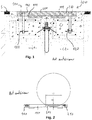
- the figure 1 shows an example of a road joint according to the prior art. It is intended to connect two parts of pavement C1, C2 separated by a slot F comprising two sets 100, 200 respectively anchored in one or other of the pavement parts on either side of the slot.
- Each set 100, 200 comprises a comb 110, 210 having a series of teeth 111, 211, the teeth of one of the combs 110, 210 being embedded in the teeth of the other comb to ensure the continuity of the upper surface of the comb.
- Each comb 110, 210 is fixed by screwing in inserts 120 embedded in concrete.
- the invention aims to provide a roadway seal with characteristics adapted to the passage of narrow wheels.
- the invention relates to a road joint for connecting two parts of pavement separated by a slot comprising two sets respectively anchored in one or the other part of the roadway on either side of the slot, each set comprising a comb having a series of teeth, the teeth of one of the combs being nested in the teeth of the other comb to ensure the continuity of the upper surface of the roadway when the parts of the road are struggling between a close position in which the slot is the narrowest and a spaced apart position in which the slot is widest, the seal being characterized in that it comprises retractable means adapted to fill, at least partially, the spaces between a first and second adjacent teeth of the same comb and a third tooth of the other comb inserted between the first and second teeth.
- retractable means supports the narrow wheels of a vehicle during its passage, and thus improve the comfort and safety of the user, without preventing the passage from the close position to the remote position, and vice versa.
- the retractable means can be installed in all areas of the road joint or selectively at a passage reserved for bicycles.
- each set further comprises a soleplate extending along the slot under the comb of said assembly.
- the sole allows to support the teeth of the comb by distributing the weight constraints of the vehicles over a large surface.
- the retractable means comprise a flexible blade extending between the first and second teeth and passing under the third tooth towards the slot.
- the flexible blade is adapted to occupy the space to be filled in the remote position, presenting a face to the sky, and to retract by bending in the close position, sliding under the third tooth.
- the retractable means are thus very simple to achieve.
- the retractable means comprise a base extending under the flexible blade and fixed on the sole, the flexible blade and the base being in one piece and connected to the opposite of the third tooth.
- the base allows the attachment of the blade, while arranging its anchoring as far as possible, to allow the maximum possible bending length between the end of the third tooth and the anchor.
- the base is obtained by simply folding the blade and does not require assembly means.
- the base is fixed by bolting, the flexible blade having a light to access screws performing bolting.
- Bolting in addition to being an effective means of fixing the blade, makes it removable, which facilitates the maintenance of the structure.
- a slot is made for the passage of tools able to manipulate said heads.
- the flexible blade In a geometric arrangement, the flexible blade is bent so as to be flush with the upper surface of the roadway in a remote position. Thus it does not exceed the surface of the roadway in a remote position. When moving to the close position, the blade will tend to bend down to pass under the third tooth. Even if the space is no longer completely filled by the blade, the dimensions thereof are reduced in this position and has little effect on the narrow wheel well.
- the retractable means comprises a telescopic tube extending between the first and the second tooth facing the third tooth.
- the telescopic tube can follow the relative spacing of the combs by permanently occupying the space at the end of the third tooth.
- the telescopic tube is fixed on the soleplate by one of its ends, the other end facing the third tooth.
- the retractable means comprise a base extending under the flexible blade and fixed on the sole, the flexible blade being connected to the base by hooks opposite the third tooth.
- the separation between the base and the blade makes it possible to confer specific properties on each of the elements in order to best adapt them to the constraints they undergo.
- the mounting of the base does not require adaptation of the blade.
- the base can be made wider than the blade so that its attachment can be achieved without being obstructed by the blade.
- the hooks are formed for example by a fold at the end of the blade and the base, the folds being nested one inside the other.
- the blade comprises a U-shaped fold, bearing at the level of the base.
- This form can also be called “gooseneck”. It allows to give flexibility to the blade, while giving it a position determined by the support on the base.
- the hook system is biased in tension, without receiving a bending moment.
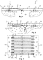
- a road joint according to a first embodiment is shown on the Figures 3 to 7 . It is intended to connect two parts of pavement C1, C2 separated by a slot F comprising two sets 1, 2 anchored respectively in one or other of the pavement portions on either side of the slot F, as in the prior art of the Figures 1 and 2 .
- Each set 1, 2 comprises a comb 10, 20 having a series of teeth 11, 21, the teeth 11, 21 of one of the combs 10, 20 being nested in the teeth 21, 11 of the other comb 20, 10 to ensure the continuity of the upper surface of the roadway when the road portions C1, C2 are struggling between a close position, as shown in FIG.
- each comb 10, 20 is fixed by screwing in inserts 120 embedded in concrete.
- Each set 1, 2 further comprises a sole 12, 22 extending along the slot F under the comb 10, 20 of said set.
- the sole 12, 22 extends between the implantation of the teeth 11, 21 of the comb 10, 20 and a line intermediate the implantation and the end of the teeth 11, 21.
- the seal comprises retractable means 3 adapted to fill, at least partially, the spaces between a first and a second tooth 11a, 11b adjacent the same comb 10 and a third tooth 21 of the other comb 20 inserted between the first and the second tooth 11a, 11b.
- the retractable means 3 relate to each comb 10, 20 and each space between the teeth 11, 21 of each comb 10, 20.
- the retractable means 3 comprise a flexible blade 30 extending between the first and second teeth 11a, 11b and passing under the third tooth 21 towards the slot F, and a base 31 extending under the flexible blade 30 and fixed on 12, 22.
- the flexible blade and the base 31 are in one piece, as shown by the Figures 6 and 7 , and connected to the opposite of the third tooth 21, that is to say at the implantation of the first and the third tooth 11a, 11b.
- the flexible blade is bent and forms an arch extending the entire length of the spaces between the teeth 11, 21 and extending into the slot F, so as to be flush with the upper surface S of the roadway in a spaced position.
- the base 31 is fixed on the sole 12, 22 by bolting two screws 32 in tapped holes of the sole 12, 22.
- the flexible blade 30 has a slot 33 facing the base 31 to access the heads of the screws 32 realizing bolting.
- the combs 10, 20 are made for example of stainless steel, likewise only soles and flexible blades. They could also be made of steel protected against corrosion by a coating.
- the slot F changes size struggling between the separated position as on the figure 4 and the close position, as shown on the figure 5 , and vice versa.
- the third tooth 21 slides on the upper face of the flexible blade 30 and pushes it downwards, inside the slot F.
- the blade 30 resumes its initial position under the effect of its elasticity. If a bicycle wheel passes over the flexible blade, it leans on it and descends only a few millimeters, without substantially penetrating between the first and second teeth 11a, 11b.
- the retractable means 3 comprises a telescopic tube 34 extending between the first and the second tooth facing the third tooth.
- the telescopic tube 34 is fixed on the sole 12, 22 by one of its ends 341, the other end 342 facing the third tooth 21, cantilevered.
- the telescopic tube 34 comprises a stand 343 which slides on the upper face of the sole 12, 22.
- the telescopic tube 34 comprises internal elastic means, not shown, which elastically hold the telescopic tube 34 in a deployed position .
- the tube seals the space between the first and second teeth permanently, without preventing the passage from the spaced apart position to the close position. If a bicycle wheel passes over the telescopic tube 34, it leans on it and descends only a few millimeters, without penetrating substantially between the first and the second tooth 11a, 11b.
- the retractable means 3 “comprise a base 31" extending under the flexible blade 30.
- the base 31 is a square section which can be continuous or the width of each blade 30". "is attached to the sole 12, while that the flexible blade 30 "is connected to the base 31" by hooks opposite the third tooth 21.
- the blade 30 “comprises a U-shaped fold 301, bearing on a first flange 311 of the base 31 which is along the flange 12.
- a second flange 312 of the base extends substantially at right angles to the first flange 311 and terminates in one of the hooks 313 of the connection with the flexible blade 30 ".
- Hook 313 having an open U shape facing the comb 10.
- One end of the blade 30 also includes a hook 302 which intermesh with the hook 313 of the base 31".
- the blade 30 In use, the blade 30 "is stretched in flexion by the support on the one hand at the hooks 313, 302, at the fold 301 and secondly under the third tooth 21.
- the blade 31" flexes during the transition from the closed position to the close position, as illustrated by the Figures 11 to 13 , the fold 301 remaining in support on the wing 311 of the base.
Description
La présente invention concerne les joints de dilatation pour ouvrage routier, encore appelés couramment joints de chaussée, destiné à assurer la continuité du chemin de roulement entre des tronçons consécutifs d'ouvrages routiers tels que des tabliers de ponts.The present invention relates to expansion joints for road structures, also commonly called road joints, intended to ensure the continuity of the road between consecutive sections of road structures such as bridge decks.
On connait déjà différents types de joints de ce genre qui, de manière générale, se composent de deux éléments métalliques, de forme allongée, fixés par des moyens d'ancrage sur deux parties de l'ouvrage routier en regard l'une de l'autre le long d'une fente, et entre lesquels est disposé un ensemble d'étanchéité déformable agencé pour assurer l'étanchéité lorsque les éléments métalliques se déplacent l'un par rapport à l'autre, notamment lorsque leur écartement varie du fait de mouvement relatifs desdites parties d'ouvrages auxquels ils sont raccordés.Various types of joints of this kind are already known which, in general, consist of two elongated metal elements fixed by anchoring means on two parts of the road structure facing one of the other along a slot, and between which is disposed a deformable seal assembly arranged to seal when the metal elements move relative to each other, especially when their spacing varies due to movement relative parts of the works to which they are connected.
Un type connu, notamment par
On connaît un autre exemple de joint de chaussée par le document
La
Si ces types de joints de chaussée donnent satisfaction pour le passage des véhicule à moteur, ils posent des problèmes pour les véhicules à roues étroites tels que les vélos. En effet, pour supporter le poids des véhicules les plus lourds, les dents doivent avoir une section suffisante. L'espace entre deux dents adjacentes a une section au moins équivalente à la section des dents, pour recevoir la dent de l'autre peigne. Alors que cet espace est comblé au moins partiellement lorsque les peignes sont au plus près l'un de l'autre, comme montré sur la
Les documents
Pour résoudre ces problèmes l'invention vise à fournir un joint de chaussée aux caractéristiques adaptée au passage de roues étroites.To solve these problems, the invention aims to provide a roadway seal with characteristics adapted to the passage of narrow wheels.
Avec ces objectifs en vue, l'invention a pour objet un joint de chaussée pour raccorder deux parties de chaussée séparées par une fente comprenant deux ensembles ancrés respectivement dans l'une ou l'autre des parties de chaussée de part et d'autre de la fente, chaque ensemble comportant un peigne comportant une série de dents, les dents de l'un des peignes étant imbriquées dans les dents de l'autre peigne pour assurer la continuité de la surface supérieure de la chaussée lorsque les parties de chaussée se débattent entre une position rapprochée dans laquelle la fente est la plus étroite et une position écartée dans laquelle la fente est la plus large, le joint étant caractérisé en ce qu'il comporte des moyens escamotables apte à combler, au moins partiellement, les espaces entre une première et une deuxième dent adjacentes d'un même peigne et une troisième dent de l'autre peigne insérée entre la première et la deuxième dent.With these objectives in view, the invention relates to a road joint for connecting two parts of pavement separated by a slot comprising two sets respectively anchored in one or the other part of the roadway on either side of the slot, each set comprising a comb having a series of teeth, the teeth of one of the combs being nested in the teeth of the other comb to ensure the continuity of the upper surface of the roadway when the parts of the road are struggling between a close position in which the slot is the narrowest and a spaced apart position in which the slot is widest, the seal being characterized in that it comprises retractable means adapted to fill, at least partially, the spaces between a first and second adjacent teeth of the same comb and a third tooth of the other comb inserted between the first and second teeth.
La présence de moyens escamotables permet de soutenir les roues étroites d'un véhicule lors de son passage, et d'améliorer ainsi le confort et la sécurité de son utilisateur, sans pour autant empêcher le passage de la position rapprochée à la position écartée, et vice-versa. Les moyens escamotables peuvent être installé dans tous les espaces du joint de chaussée ou de manière sélective, au niveau d'un passage réservé aux vélos.The presence of retractable means supports the narrow wheels of a vehicle during its passage, and thus improve the comfort and safety of the user, without preventing the passage from the close position to the remote position, and vice versa. The retractable means can be installed in all areas of the road joint or selectively at a passage reserved for bicycles.
Selon l'invention chaque ensemble comporte en outre une semelle s'étendant le long de la fente sous le peigne dudit ensemble. La semelle permet de soutenir les dents du peigne en répartissant les contraintes de poids des véhicules sur une large surface.According to the invention each set further comprises a soleplate extending along the slot under the comb of said assembly. The sole allows to support the teeth of the comb by distributing the weight constraints of the vehicles over a large surface.
Les moyens escamotables comportent une lame flexible s'étendant entre la première et la deuxième dent et passant sous la troisième dent vers la fente. La lame flexible est apte à occuper ainsi l'espace à combler dans la position écartée, en présentant une face vers le ciel, et à s'escamoter par sa flexion en position rapprochée, en glissant sous la troisième dent. Les moyens escamotables sont ainsi très simples à réaliser.The retractable means comprise a flexible blade extending between the first and second teeth and passing under the third tooth towards the slot. The flexible blade is adapted to occupy the space to be filled in the remote position, presenting a face to the sky, and to retract by bending in the close position, sliding under the third tooth. The retractable means are thus very simple to achieve.
Selon une disposition constructive, les moyens escamotables comportent une base s'étendant sous la lame flexible et fixée sur la semelle, la lame flexible et la base étant d'un seul tenant et reliées à l'opposé de la troisième dent. La base permet la fixation de la lame, tout en disposant son ancrage au plus loin possible, afin de laisser le maximum de longueur de flexion possible entre l'extrémité de la troisième dent et l'ancrage. De plus, la base est obtenue par le simple pliage de la lame et ne nécessite pas de moyens d'assemblage.According to a constructive arrangement, the retractable means comprise a base extending under the flexible blade and fixed on the sole, the flexible blade and the base being in one piece and connected to the opposite of the third tooth. The base allows the attachment of the blade, while arranging its anchoring as far as possible, to allow the maximum possible bending length between the end of the third tooth and the anchor. In addition, the base is obtained by simply folding the blade and does not require assembly means.
De manière complémentaire, la base est fixée par boulonnage, la lame flexible comportant une lumière pour accéder à des vis réalisant le boulonnage. Le boulonnage, en plus d'être un moyen de fixation efficace de la lame, rend celle-ci amovible, ce qui facilite la maintenance de l'ouvrage. Toutefois, pour accéder aux têtes de vis ou de boulons, on réalise une fente pour le passage des outils aptes à manoeuvrer lesdites têtes.In a complementary manner, the base is fixed by bolting, the flexible blade having a light to access screws performing bolting. Bolting, in addition to being an effective means of fixing the blade, makes it removable, which facilitates the maintenance of the structure. However, to access the heads of screws or bolts, a slot is made for the passage of tools able to manipulate said heads.
Selon une disposition géométrique, la lame flexible est cintrée de sorte à affleurer la surface supérieure de la chaussée en position écartée. Ainsi elle ne dépasse pas de la surface de la chaussée en position écartée. Lors du passage en position rapprochée, la lame aura tendance à fléchir vers le bas pour passer sous la troisième dent. Même si l'espace n'est plus complètement comblé par la lame, les dimensions de celui-ci sont réduites dans cette position et n'affecte que peu le passage de roue étroite.In a geometric arrangement, the flexible blade is bent so as to be flush with the upper surface of the roadway in a remote position. Thus it does not exceed the surface of the roadway in a remote position. When moving to the close position, the blade will tend to bend down to pass under the third tooth. Even if the space is no longer completely filled by the blade, the dimensions thereof are reduced in this position and has little effect on the narrow wheel well.
Selon un deuxième mode de réalisation non revendiqué, qui ne fait pas partie de l'invention, les moyens escamotables comporte un tube télescopique s'étendant entre la première et la deuxième dent en regard de la troisième dent. Le tube télescopique peut suivre l'écartement relatif des peignes en occupant en permanence l'espace à l'extrémité de la troisième dent.According to a second embodiment not claimed, which is not part of the invention, the retractable means comprises a telescopic tube extending between the first and the second tooth facing the third tooth. The telescopic tube can follow the relative spacing of the combs by permanently occupying the space at the end of the third tooth.
Selon une disposition constructive, le tube télescopique est fixé sur la semelle par l'une de ses extrémités, l'autre extrémité étant en regard de la troisième dent.According to a constructive arrangement, the telescopic tube is fixed on the soleplate by one of its ends, the other end facing the third tooth.
Selon un troisième mode de réalisation, les moyens escamotables comportent une base s'étendant sous la lame flexible et fixée sur la semelle, la lame flexible étant reliée à la base par crochets à l'opposé de la troisième dent. La séparation entre la base et la lame permet de conférer des propriétés spécifiques à chacun des éléments pour les adapter au mieux aux contraintes qu'ils subissent. De plus, le montage de la base, par exemple par vissage, ne nécessite pas d'adaptation de la lame. La base peut être réalisée plus large que la lame de manière que sa fixation peut être réalisée sans être gênée par la lame. Les crochets sont formés par exemple par un pli à l'extrémité de la lame et de la base, les plis étant imbriqués l'un dans l'autre.According to a third embodiment, the retractable means comprise a base extending under the flexible blade and fixed on the sole, the flexible blade being connected to the base by hooks opposite the third tooth. The separation between the base and the blade makes it possible to confer specific properties on each of the elements in order to best adapt them to the constraints they undergo. In addition, the mounting of the base, for example by screwing, does not require adaptation of the blade. The base can be made wider than the blade so that its attachment can be achieved without being obstructed by the blade. The hooks are formed for example by a fold at the end of the blade and the base, the folds being nested one inside the other.
Selon un perfectionnement, la lame comporte un repli en forme de U, venant en appui au niveau de la base. Cette forme peut aussi être appelée « col de cygne ». Elle permet de donner de la souplesse à la lame, tout en lui donnant une position déterminée par l'appui sur la base. De plus, le système de crochets est sollicité en traction, sans recevoir de moment fléchissant.According to an improvement, the blade comprises a U-shaped fold, bearing at the level of the base. This form can also be called "gooseneck". It allows to give flexibility to the blade, while giving it a position determined by the support on the base. In addition, the hook system is biased in tension, without receiving a bending moment.
Pour une meilleure compréhension de l'invention, il est fait référence à la description qui suit et aux dessins annexés, parmi lesquels :
- la
figure 1 est une vue en coupe d'un joint de chaussée selon l'art antérieur ; - la
figure 2 est une vue simplifiée en coupe du joint de lafigure 1 , en position écartée, montrant le passage d'une roue d'un vélo ; - la
figure 3 est une vue de dessus d'un joint selon un premier mode de réalisation de l'invention, en position écartée;
- la
figure 4 est une vue en coupe similaire selon la ligne IV-IV de lafigure 3 ; - la
figure 5 est une vue similaire à lafigure 4 en position intermédiaire; - la
figure 6 est une vue en perspective de la lame de lafigure 4 ; - la
figure 7 est une vue du détail VII de lafigure 6 ; - la
figure 8 est une vue de dessus d'un joint selon un deuxième mode de réalisation qui ne fait pas partie de l'invention ; - la
figure 9 est une vue en coupe selon la ligne IX-IX de lafigure 8 ; - la
figure 10 est une vue similaire à lafigure 9 en position rapprochée; - les
figures 11 à 13 sont des vues en coupe similaires à lafigure 4 d'un joint selon un troisième mode de réalisation de l'invention, respectivement en position écartée, intermédiaire et rapprochée.
- the
figure 1 is a sectional view of a road joint according to the prior art; - the
figure 2 is a simplified sectional view of the seal of thefigure 1 , in the spread position, showing the passage of a wheel of a bicycle; - the
figure 3 is a top view of a joint according to a first mode of embodiment of the invention, in a remote position;
- the
figure 4 is a similar sectional view along line IV-IV of thefigure 3 ; - the
figure 5 is a view similar to thefigure 4 in the intermediate position; - the
figure 6 is a perspective view of the blade of thefigure 4 ; - the
figure 7 is a detail view VII of thefigure 6 ; - the
figure 8 is a top view of a seal according to a second embodiment which does not form part of the invention; - the
figure 9 is a sectional view along the line IX-IX of thefigure 8 ; - the
figure 10 is a view similar to thefigure 9 in a close position; - the
Figures 11 to 13 are sectional views similar to thefigure 4 a seal according to a third embodiment of the invention, respectively in the spaced apart, intermediate and close position.
Un joint de chaussée selon une premier mode de réalisation est montré sur les
Le joint comporte des moyens escamotables 3 apte à combler, au moins partiellement, les espaces entre une première et une deuxième dent 11a, 11b adjacentes d'un même peigne 10 et une troisième dent 21 de l'autre peigne 20 insérée entre la première et la deuxième dent 11a, 11b. Au final, les moyens escamotables 3 concernent chaque peigne 10, 20 et chaque espace entre les dents 11, 21 de chaque peigne 10, 20.The seal comprises retractable means 3 adapted to fill, at least partially, the spaces between a first and a
Les moyens escamotables 3 comportent une lame 30 flexible, s'étendant entre la première et la deuxième dent 11a, 11b et passant sous la troisième dent 21 vers la fente F, et une base 31 s'étendant sous la lame 30 flexible et fixée sur la semelle 12, 22. Dans ce mode de réalisation, la lame 30 flexible et la base 31 sont d'un seul tenant, comme montré par les
La base 31 est fixée sur la semelle 12, 22 par boulonnage de deux vis 32 dans des trous taraudés de la semelle 12, 22. La lame 30 flexible comporte une lumière 33 en regard de la base 31 pour accéder aux têtes des vis 32 réalisant le boulonnage.The
Les peignes 10, 20 sont réalisés par exemple en acier inoxydable, de même que les semelles et les lames 30 flexibles. Ils pourraient aussi être réalisés dans en acier protégé contre la corrosion par un revêtement.The
En fonctionnement, en fonction des contraintes sur l'ouvrage, en particulier en fonction des températures, la fente F change de taille se débattant entre la position écartée comme sur la
Dans un deuxième mode de réalisation, qui ne fait pas partie de l'invention, montré sur les
Dans un troisième mode de réalisation, montré sur les
En utilisation, la lame 30" est tendue en flexion par l'appui d'une part au niveau des crochets 313, 302, au niveau du repli 301 et d'autre part sous la troisième dent 21. La lame 31" fléchit lors du passage de la position écartée à la position rapprochée, comme l'illustrent les
Claims (6)
- Roadway joint to connect two pavement sections (C1, C2) separated by a gap (F) comprising two assemblies (1, 2) anchored respectively in one or other of the pavement sections (C1, C2) on either side of the gap (F), each assembly (1, 2) comprising a finger plate (10, 20) comprising a series of teeth (11, 21), the teeth (11, 21) of one of the finger plates (10, 20) being interlocked in the teeth (21, 11) of the other finger plate (20, 10) to ensure the continuity of the upper surface (S) of the pavement when the pavement sections (C1, C2) move between a near position where the gap (F) is at its narrowest and a spaced-apart position where the gap (F) is at its widest, the joint being characterised in that it comprises retractable means (3, 3') capable of filling, at least partially, the spaces between an adjacent first and second tooth (11a, 11b) on the same finger plate (10, 20) and a third tooth (21) on the other finger plate (10, 20) inserted between the first and the second tooth (11a, 11b),
the retractable means (3, 3') comprising a flexible blade (30) extending between the first and the second tooth (11a, 11b) and passing under the third tooth (21) towards the gap (F),
each assembly (1, 2) further comprising a base plate (12, 22) extending along the gap (F) under the finger plate (10, 20) of said assembly,
characterised in that the retractable means (3, 3') comprise a base (31) extending under the flexible blade (30) and attached to the base plate (12, 22). - Roadway joint according to claim 1, where the flexible blade (30) and the base (31) are in one piece and connected opposite the third tooth (21).
- Roadway joint according to claim 1 or claim 2, where the base (31) is attached by bolting, the flexible blade (30) comprising an aperture to provide access to the screws ensuring the bolting.
- Roadway joint according to claim 1, where the flexible blade (30") is connected to the base (31") by hooks opposite the third tooth (21).
- Roadway joint according to claim 4, where the blade (30") comprises a U-shaped fold (301), resting on the base (31").
- Roadway joint according to one of the previous claims, where the flexible blade (30) is bent to be flush with the upper surface (S) of the pavement in the spaced-apart position.
Priority Applications (4)
| Application Number | Priority Date | Filing Date | Title |
|---|---|---|---|
| DK16182742.3T DK3279399T3 (en) | 2016-08-04 | 2016-08-04 | ROAD TRANSITION TO ROADWORK |
| SI201630343T SI3279399T1 (en) | 2016-08-04 | 2016-08-04 | Road joint for road structure |
| EP16182742.3A EP3279399B1 (en) | 2016-08-04 | 2016-08-04 | Road joint for road structure |
| AU2017208357A AU2017208357A1 (en) | 2016-08-04 | 2017-07-28 | Roadway joint for road structure |
Applications Claiming Priority (1)
| Application Number | Priority Date | Filing Date | Title |
|---|---|---|---|
| EP16182742.3A EP3279399B1 (en) | 2016-08-04 | 2016-08-04 | Road joint for road structure |
Publications (2)
| Publication Number | Publication Date |
|---|---|
| EP3279399A1 EP3279399A1 (en) | 2018-02-07 |
| EP3279399B1 true EP3279399B1 (en) | 2019-05-29 |
Family
ID=56609702
Family Applications (1)
| Application Number | Title | Priority Date | Filing Date |
|---|---|---|---|
| EP16182742.3A Active EP3279399B1 (en) | 2016-08-04 | 2016-08-04 | Road joint for road structure |
Country Status (4)
| Country | Link |
|---|---|
| EP (1) | EP3279399B1 (en) |
| AU (1) | AU2017208357A1 (en) |
| DK (1) | DK3279399T3 (en) |
| SI (1) | SI3279399T1 (en) |
Families Citing this family (2)
| Publication number | Priority date | Publication date | Assignee | Title |
|---|---|---|---|---|
| KR101795337B1 (en) * | 2017-01-25 | 2017-11-08 | 주식회사 케이이테크 | Finger joint with a bridging cover plate |
| CN110468700B (en) * | 2019-09-17 | 2020-11-17 | 衡水中盛工程橡胶有限公司 | Multifunctional expansion joint device for bridge |
Family Cites Families (6)
| Publication number | Priority date | Publication date | Assignee | Title |
|---|---|---|---|---|
| FR2573456B1 (en) | 1984-11-20 | 1987-01-30 | Freyssinet Int Stup | GROUND JOINTS |
| AT413829B (en) * | 1999-03-02 | 2006-06-15 | Reisner & Wolff Eng | DEVICE FOR BRIDGING EXTENSIONS IN ROADS |
| FR2902118B1 (en) | 2006-06-13 | 2008-08-15 | Equip Tech Pour L'ind De La Co | EXPANSION JOINT FOR ROAD WORK |
| CN101956366B (en) * | 2009-12-29 | 2016-09-28 | 吴树超 | A formula bridge extension joint mutually |
| WO2011126413A2 (en) * | 2011-01-31 | 2011-10-13 | Kozlachkov Sergey Waleriewich | The expansion joint |
| CN102966036B (en) * | 2012-11-18 | 2015-10-21 | 吴树超 | Chain type seamless bridge telescopic device |
-
2016
- 2016-08-04 SI SI201630343T patent/SI3279399T1/en unknown
- 2016-08-04 DK DK16182742.3T patent/DK3279399T3/en active
- 2016-08-04 EP EP16182742.3A patent/EP3279399B1/en active Active
-
2017
- 2017-07-28 AU AU2017208357A patent/AU2017208357A1/en not_active Abandoned
Non-Patent Citations (1)
| Title |
|---|
| None * |
Also Published As
| Publication number | Publication date |
|---|---|
| EP3279399A1 (en) | 2018-02-07 |
| DK3279399T3 (en) | 2019-09-09 |
| AU2017208357A1 (en) | 2018-02-22 |
| SI3279399T1 (en) | 2020-03-31 |
Similar Documents
| Publication | Publication Date | Title |
|---|---|---|
| EP2943693B1 (en) | Clamp for fastening a panel to a holder and resulting assembly | |
| WO1992001179A1 (en) | Inflatable-joint sealing device for movable doors and panels | |
| WO2018114913A1 (en) | Guiding of sliding glass panel, particularly for a motor vehicle | |
| EP3279399B1 (en) | Road joint for road structure | |
| EP1184515A1 (en) | Road safety barrier with at least one safety parapet | |
| FR2931742A1 (en) | Base for seat of motor vehicle, has guiding and setting systems constituted by element in longitudinal translation with respect to another element in operating direction and along path equal to path of nose | |
| CA2000622C (en) | Seat holder for public transport vehicle and seat fitted with holder | |
| EP2619394B1 (en) | Sill and opening-leaf assembly | |
| FR2783854A1 (en) | LEVEL TAKE-UP THRESHOLD | |
| WO2015128562A1 (en) | Vehicle seat adjustment track, deflector intended for such a track and vehicle thus equipped | |
| EP2980347A1 (en) | Telescoping ladder comprising ladder sections having different densities | |
| FR3036312A1 (en) | DERAILLEUR'S PATTERN | |
| EP2509851A1 (en) | Flexible aerodynamic device | |
| EP3081719A1 (en) | Connecting profile for a roof element, in particular for telescopic swimming-pool shelter | |
| FR2836495A1 (en) | Motor road safety barrier sign fastening has two jaws of which one is equipped with fittings for concrete or metal barrier | |
| EP2310591B1 (en) | Double tab fastener for securing a ridge or hip strip | |
| FR2899605A1 (en) | Elastic double plate for fixing adjacent rails, has rails locked on plate by bolts and clamps, where plate is presented with variable thickness for obtaining proper inertia adapted to variation of elastic deformations from load of rails | |
| EP2501876B1 (en) | Railing formed of a set of ready-to-assemble detached parts | |
| FR2968740A1 (en) | Sealing piece for sealing gap between two photovoltaic panels in roof, has longitudinal anchor including two sides, where upper sealing lip protrudes laterally with respect to upper portion of one side of anchor | |
| CH680046A5 (en) | ||
| FR3071785B1 (en) | SEAT STRUCTURE OF A MOTOR VEHICLE WITH A CLAMP FOR HOLDING A COVER. | |
| FR2889118A1 (en) | Seat assembly for vehicle, has anchoring elements connected to seat and comprising anchoring heads connected to central bodies, and rollers displaced by rolling on lower and upper edges of rail | |
| FR2954065A1 (en) | Suspension device for use between spring-mattress and frame of bed, has body passing from inactive to active states during deformation of suspension section in direction of bringing together bearing section with fixation section | |
| FR2865984A1 (en) | Floor for flexible connection between carriages of railway vehicles has flexible mat with downward-projecting ribs that engage with troughs of floor corrugations | |
| FR2569224A1 (en) | CLAMPING CONNECTION SYSTEM FOR UNDERGROUND GALLERY SUPPORT ARRAYS |
Legal Events
| Date | Code | Title | Description |
|---|---|---|---|
| PUAI | Public reference made under article 153(3) epc to a published international application that has entered the european phase |
Free format text: ORIGINAL CODE: 0009012 |
|
| STAA | Information on the status of an ep patent application or granted ep patent |
Free format text: STATUS: THE APPLICATION HAS BEEN PUBLISHED |
|
| AK | Designated contracting states |
Kind code of ref document: A1 Designated state(s): AL AT BE BG CH CY CZ DE DK EE ES FI FR GB GR HR HU IE IS IT LI LT LU LV MC MK MT NL NO PL PT RO RS SE SI SK SM TR |
|
| AX | Request for extension of the european patent |
Extension state: BA ME |
|
| STAA | Information on the status of an ep patent application or granted ep patent |
Free format text: STATUS: REQUEST FOR EXAMINATION WAS MADE |
|
| 17P | Request for examination filed |
Effective date: 20180802 |
|
| RBV | Designated contracting states (corrected) |
Designated state(s): AL AT BE BG CH CY CZ DE DK EE ES FI FR GB GR HR HU IE IS IT LI LT LU LV MC MK MT NL NO PL PT RO RS SE SI SK SM TR |
|
| GRAP | Despatch of communication of intention to grant a patent |
Free format text: ORIGINAL CODE: EPIDOSNIGR1 |
|
| STAA | Information on the status of an ep patent application or granted ep patent |
Free format text: STATUS: GRANT OF PATENT IS INTENDED |
|
| INTG | Intention to grant announced |
Effective date: 20181218 |
|
| GRAS | Grant fee paid |
Free format text: ORIGINAL CODE: EPIDOSNIGR3 |
|
| GRAA | (expected) grant |
Free format text: ORIGINAL CODE: 0009210 |
|
| STAA | Information on the status of an ep patent application or granted ep patent |
Free format text: STATUS: THE PATENT HAS BEEN GRANTED |
|
| AK | Designated contracting states |
Kind code of ref document: B1 Designated state(s): AL AT BE BG CH CY CZ DE DK EE ES FI FR GB GR HR HU IE IS IT LI LT LU LV MC MK MT NL NO PL PT RO RS SE SI SK SM TR |
|
| REG | Reference to a national code |
Ref country code: GB Ref legal event code: FG4D Free format text: NOT ENGLISH |
|
| REG | Reference to a national code |
Ref country code: CH Ref legal event code: EP |
|
| REG | Reference to a national code |
Ref country code: AT Ref legal event code: REF Ref document number: 1138336 Country of ref document: AT Kind code of ref document: T Effective date: 20190615 |
|
| REG | Reference to a national code |
Ref country code: DE Ref legal event code: R096 Ref document number: 602016014516 Country of ref document: DE |
|
| REG | Reference to a national code |
Ref country code: IE Ref legal event code: FG4D Free format text: LANGUAGE OF EP DOCUMENT: FRENCH |
|
| REG | Reference to a national code |
Ref country code: DK Ref legal event code: T3 Effective date: 20190904 |
|
| REG | Reference to a national code |
Ref country code: SE Ref legal event code: TRGR |
|
| REG | Reference to a national code |
Ref country code: NL Ref legal event code: MP Effective date: 20190529 |
|
| REG | Reference to a national code |
Ref country code: LT Ref legal event code: MG4D |
|
| REG | Reference to a national code |
Ref country code: NO Ref legal event code: T2 Effective date: 20190529 |
|
| PG25 | Lapsed in a contracting state [announced via postgrant information from national office to epo] |
Ref country code: HR Free format text: LAPSE BECAUSE OF FAILURE TO SUBMIT A TRANSLATION OF THE DESCRIPTION OR TO PAY THE FEE WITHIN THE PRESCRIBED TIME-LIMIT Effective date: 20190529 Ref country code: LT Free format text: LAPSE BECAUSE OF FAILURE TO SUBMIT A TRANSLATION OF THE DESCRIPTION OR TO PAY THE FEE WITHIN THE PRESCRIBED TIME-LIMIT Effective date: 20190529 Ref country code: AL Free format text: LAPSE BECAUSE OF FAILURE TO SUBMIT A TRANSLATION OF THE DESCRIPTION OR TO PAY THE FEE WITHIN THE PRESCRIBED TIME-LIMIT Effective date: 20190529 Ref country code: ES Free format text: LAPSE BECAUSE OF FAILURE TO SUBMIT A TRANSLATION OF THE DESCRIPTION OR TO PAY THE FEE WITHIN THE PRESCRIBED TIME-LIMIT Effective date: 20190529 Ref country code: PT Free format text: LAPSE BECAUSE OF FAILURE TO SUBMIT A TRANSLATION OF THE DESCRIPTION OR TO PAY THE FEE WITHIN THE PRESCRIBED TIME-LIMIT Effective date: 20190930 |
|
| PGFP | Annual fee paid to national office [announced via postgrant information from national office to epo] |
Ref country code: FI Payment date: 20190902 Year of fee payment: 4 Ref country code: DK Payment date: 20190902 Year of fee payment: 4 Ref country code: SE Payment date: 20190814 Year of fee payment: 4 |
|
| PG25 | Lapsed in a contracting state [announced via postgrant information from national office to epo] |
Ref country code: BG Free format text: LAPSE BECAUSE OF FAILURE TO SUBMIT A TRANSLATION OF THE DESCRIPTION OR TO PAY THE FEE WITHIN THE PRESCRIBED TIME-LIMIT Effective date: 20190829 Ref country code: RS Free format text: LAPSE BECAUSE OF FAILURE TO SUBMIT A TRANSLATION OF THE DESCRIPTION OR TO PAY THE FEE WITHIN THE PRESCRIBED TIME-LIMIT Effective date: 20190529 Ref country code: GR Free format text: LAPSE BECAUSE OF FAILURE TO SUBMIT A TRANSLATION OF THE DESCRIPTION OR TO PAY THE FEE WITHIN THE PRESCRIBED TIME-LIMIT Effective date: 20190830 Ref country code: LV Free format text: LAPSE BECAUSE OF FAILURE TO SUBMIT A TRANSLATION OF THE DESCRIPTION OR TO PAY THE FEE WITHIN THE PRESCRIBED TIME-LIMIT Effective date: 20190529 |
|
| RAP2 | Party data changed (patent owner data changed or rights of a patent transferred) |
Owner name: EQUIPEMENTS TECHNIQUES POUR L'INDUSTRIE DE LA CONS |
|
| REG | Reference to a national code |
Ref country code: AT Ref legal event code: MK05 Ref document number: 1138336 Country of ref document: AT Kind code of ref document: T Effective date: 20190529 |
|
| PG25 | Lapsed in a contracting state [announced via postgrant information from national office to epo] |
Ref country code: EE Free format text: LAPSE BECAUSE OF FAILURE TO SUBMIT A TRANSLATION OF THE DESCRIPTION OR TO PAY THE FEE WITHIN THE PRESCRIBED TIME-LIMIT Effective date: 20190529 Ref country code: NL Free format text: LAPSE BECAUSE OF FAILURE TO SUBMIT A TRANSLATION OF THE DESCRIPTION OR TO PAY THE FEE WITHIN THE PRESCRIBED TIME-LIMIT Effective date: 20190529 Ref country code: SK Free format text: LAPSE BECAUSE OF FAILURE TO SUBMIT A TRANSLATION OF THE DESCRIPTION OR TO PAY THE FEE WITHIN THE PRESCRIBED TIME-LIMIT Effective date: 20190529 Ref country code: AT Free format text: LAPSE BECAUSE OF FAILURE TO SUBMIT A TRANSLATION OF THE DESCRIPTION OR TO PAY THE FEE WITHIN THE PRESCRIBED TIME-LIMIT Effective date: 20190529 Ref country code: CZ Free format text: LAPSE BECAUSE OF FAILURE TO SUBMIT A TRANSLATION OF THE DESCRIPTION OR TO PAY THE FEE WITHIN THE PRESCRIBED TIME-LIMIT Effective date: 20190529 Ref country code: RO Free format text: LAPSE BECAUSE OF FAILURE TO SUBMIT A TRANSLATION OF THE DESCRIPTION OR TO PAY THE FEE WITHIN THE PRESCRIBED TIME-LIMIT Effective date: 20190529 |
|
| PG25 | Lapsed in a contracting state [announced via postgrant information from national office to epo] |
Ref country code: SM Free format text: LAPSE BECAUSE OF FAILURE TO SUBMIT A TRANSLATION OF THE DESCRIPTION OR TO PAY THE FEE WITHIN THE PRESCRIBED TIME-LIMIT Effective date: 20190529 Ref country code: IT Free format text: LAPSE BECAUSE OF FAILURE TO SUBMIT A TRANSLATION OF THE DESCRIPTION OR TO PAY THE FEE WITHIN THE PRESCRIBED TIME-LIMIT Effective date: 20190529 |
|
| REG | Reference to a national code |
Ref country code: DE Ref legal event code: R097 Ref document number: 602016014516 Country of ref document: DE Ref country code: DE Ref legal event code: R119 Ref document number: 602016014516 Country of ref document: DE |
|
| PG25 | Lapsed in a contracting state [announced via postgrant information from national office to epo] |
Ref country code: TR Free format text: LAPSE BECAUSE OF FAILURE TO SUBMIT A TRANSLATION OF THE DESCRIPTION OR TO PAY THE FEE WITHIN THE PRESCRIBED TIME-LIMIT Effective date: 20190529 |
|
| PLBE | No opposition filed within time limit |
Free format text: ORIGINAL CODE: 0009261 |
|
| STAA | Information on the status of an ep patent application or granted ep patent |
Free format text: STATUS: NO OPPOSITION FILED WITHIN TIME LIMIT |
|
| PG25 | Lapsed in a contracting state [announced via postgrant information from national office to epo] |
Ref country code: PL Free format text: LAPSE BECAUSE OF FAILURE TO SUBMIT A TRANSLATION OF THE DESCRIPTION OR TO PAY THE FEE WITHIN THE PRESCRIBED TIME-LIMIT Effective date: 20190529 |
|
| 26N | No opposition filed |
Effective date: 20200303 |
|
| PG25 | Lapsed in a contracting state [announced via postgrant information from national office to epo] |
Ref country code: LI Free format text: LAPSE BECAUSE OF NON-PAYMENT OF DUE FEES Effective date: 20190831 Ref country code: CH Free format text: LAPSE BECAUSE OF NON-PAYMENT OF DUE FEES Effective date: 20190831 Ref country code: MC Free format text: LAPSE BECAUSE OF FAILURE TO SUBMIT A TRANSLATION OF THE DESCRIPTION OR TO PAY THE FEE WITHIN THE PRESCRIBED TIME-LIMIT Effective date: 20190529 Ref country code: LU Free format text: LAPSE BECAUSE OF NON-PAYMENT OF DUE FEES Effective date: 20190804 |
|
| PG25 | Lapsed in a contracting state [announced via postgrant information from national office to epo] |
Ref country code: DE Free format text: LAPSE BECAUSE OF NON-PAYMENT OF DUE FEES Effective date: 20200303 Ref country code: IE Free format text: LAPSE BECAUSE OF NON-PAYMENT OF DUE FEES Effective date: 20190804 |
|
| PGFP | Annual fee paid to national office [announced via postgrant information from national office to epo] |
Ref country code: SI Payment date: 20200803 Year of fee payment: 5 |
|
| REG | Reference to a national code |
Ref country code: FI Ref legal event code: MAE |
|
| REG | Reference to a national code |
Ref country code: DK Ref legal event code: EBP Effective date: 20200831 |
|
| REG | Reference to a national code |
Ref country code: SE Ref legal event code: EUG |
|
| PG25 | Lapsed in a contracting state [announced via postgrant information from national office to epo] |
Ref country code: FI Free format text: LAPSE BECAUSE OF NON-PAYMENT OF DUE FEES Effective date: 20200804 |
|
| PG25 | Lapsed in a contracting state [announced via postgrant information from national office to epo] |
Ref country code: SE Free format text: LAPSE BECAUSE OF NON-PAYMENT OF DUE FEES Effective date: 20200805 Ref country code: CY Free format text: LAPSE BECAUSE OF FAILURE TO SUBMIT A TRANSLATION OF THE DESCRIPTION OR TO PAY THE FEE WITHIN THE PRESCRIBED TIME-LIMIT Effective date: 20190529 |
|
| PG25 | Lapsed in a contracting state [announced via postgrant information from national office to epo] |
Ref country code: IS Free format text: LAPSE BECAUSE OF FAILURE TO SUBMIT A TRANSLATION OF THE DESCRIPTION OR TO PAY THE FEE WITHIN THE PRESCRIBED TIME-LIMIT Effective date: 20190929 |
|
| PG25 | Lapsed in a contracting state [announced via postgrant information from national office to epo] |
Ref country code: MT Free format text: LAPSE BECAUSE OF FAILURE TO SUBMIT A TRANSLATION OF THE DESCRIPTION OR TO PAY THE FEE WITHIN THE PRESCRIBED TIME-LIMIT Effective date: 20190529 Ref country code: HU Free format text: LAPSE BECAUSE OF FAILURE TO SUBMIT A TRANSLATION OF THE DESCRIPTION OR TO PAY THE FEE WITHIN THE PRESCRIBED TIME-LIMIT; INVALID AB INITIO Effective date: 20160804 |
|
| PG25 | Lapsed in a contracting state [announced via postgrant information from national office to epo] |
Ref country code: DK Free format text: LAPSE BECAUSE OF NON-PAYMENT OF DUE FEES Effective date: 20200831 |
|
| REG | Reference to a national code |
Ref country code: SI Ref legal event code: KO00 Effective date: 20220407 |
|
| PG25 | Lapsed in a contracting state [announced via postgrant information from national office to epo] |
Ref country code: MK Free format text: LAPSE BECAUSE OF FAILURE TO SUBMIT A TRANSLATION OF THE DESCRIPTION OR TO PAY THE FEE WITHIN THE PRESCRIBED TIME-LIMIT Effective date: 20190529 |
|
| PGFP | Annual fee paid to national office [announced via postgrant information from national office to epo] |
Ref country code: GB Payment date: 20220831 Year of fee payment: 7 |
|
| PGFP | Annual fee paid to national office [announced via postgrant information from national office to epo] |
Ref country code: BE Payment date: 20220831 Year of fee payment: 7 |
|
| PGFP | Annual fee paid to national office [announced via postgrant information from national office to epo] |
Ref country code: NO Payment date: 20230829 Year of fee payment: 8 |
|
| PGFP | Annual fee paid to national office [announced via postgrant information from national office to epo] |
Ref country code: FR Payment date: 20230816 Year of fee payment: 8 |
|
| GBPC | Gb: european patent ceased through non-payment of renewal fee |
Effective date: 20230804 |