EP2980347A1 - Telescoping ladder comprising ladder sections having different densities - Google Patents
Telescoping ladder comprising ladder sections having different densities Download PDFInfo
- Publication number
- EP2980347A1 EP2980347A1 EP15178548.2A EP15178548A EP2980347A1 EP 2980347 A1 EP2980347 A1 EP 2980347A1 EP 15178548 A EP15178548 A EP 15178548A EP 2980347 A1 EP2980347 A1 EP 2980347A1
- Authority
- EP
- European Patent Office
- Prior art keywords
- ladder
- section
- bar
- proximal end
- uprights
- Prior art date
- Legal status (The legal status is an assumption and is not a legal conclusion. Google has not performed a legal analysis and makes no representation as to the accuracy of the status listed.)
- Withdrawn
Links
- 239000000463 material Substances 0.000 claims abstract description 34
- 229920000049 Carbon (fiber) Polymers 0.000 claims description 11
- 239000004917 carbon fiber Substances 0.000 claims description 11
- 238000004026 adhesive bonding Methods 0.000 claims description 2
- 229910000831 Steel Inorganic materials 0.000 description 5
- 239000002131 composite material Substances 0.000 description 5
- 238000010586 diagram Methods 0.000 description 5
- VNWKTOKETHGBQD-UHFFFAOYSA-N methane Chemical compound C VNWKTOKETHGBQD-UHFFFAOYSA-N 0.000 description 5
- 239000010959 steel Substances 0.000 description 5
- XAGFODPZIPBFFR-UHFFFAOYSA-N aluminium Chemical compound [Al] XAGFODPZIPBFFR-UHFFFAOYSA-N 0.000 description 4
- 229910052782 aluminium Inorganic materials 0.000 description 4
- 230000005484 gravity Effects 0.000 description 4
- RTAQQCXQSZGOHL-UHFFFAOYSA-N Titanium Chemical compound [Ti] RTAQQCXQSZGOHL-UHFFFAOYSA-N 0.000 description 2
- 229910052799 carbon Inorganic materials 0.000 description 2
- 230000003247 decreasing effect Effects 0.000 description 2
- 239000011152 fibreglass Substances 0.000 description 2
- 238000004519 manufacturing process Methods 0.000 description 2
- 239000010936 titanium Substances 0.000 description 2
- 229910052719 titanium Inorganic materials 0.000 description 2
- OKTJSMMVPCPJKN-UHFFFAOYSA-N Carbon Chemical compound [C] OKTJSMMVPCPJKN-UHFFFAOYSA-N 0.000 description 1
- 230000000295 complement effect Effects 0.000 description 1
- 230000000694 effects Effects 0.000 description 1
- 230000003014 reinforcing effect Effects 0.000 description 1
- XLYOFNOQVPJJNP-UHFFFAOYSA-N water Substances O XLYOFNOQVPJJNP-UHFFFAOYSA-N 0.000 description 1
Images
Classifications
-
- E—FIXED CONSTRUCTIONS
- E06—DOORS, WINDOWS, SHUTTERS, OR ROLLER BLINDS IN GENERAL; LADDERS
- E06C—LADDERS
- E06C5/00—Ladders characterised by being mounted on undercarriages or vehicles Securing ladders on vehicles
- E06C5/02—Ladders characterised by being mounted on undercarriages or vehicles Securing ladders on vehicles with rigid longitudinal members
- E06C5/04—Ladders characterised by being mounted on undercarriages or vehicles Securing ladders on vehicles with rigid longitudinal members capable of being elevated or extended ; Fastening means during transport, e.g. mechanical, hydraulic
-
- E—FIXED CONSTRUCTIONS
- E06—DOORS, WINDOWS, SHUTTERS, OR ROLLER BLINDS IN GENERAL; LADDERS
- E06C—LADDERS
- E06C7/00—Component parts, supporting parts, or accessories
- E06C7/18—Devices for preventing persons from falling
- E06C7/181—Additional gripping devices, e.g. handrails
- E06C7/183—Additional gripping devices, e.g. handrails situated along the ladder
-
- E—FIXED CONSTRUCTIONS
- E06—DOORS, WINDOWS, SHUTTERS, OR ROLLER BLINDS IN GENERAL; LADDERS
- E06C—LADDERS
- E06C1/00—Ladders in general
- E06C1/02—Ladders in general with rigid longitudinal member or members
- E06C1/04—Ladders for resting against objects, e.g. walls poles, trees
- E06C1/08—Ladders for resting against objects, e.g. walls poles, trees multi-part
- E06C1/12—Ladders for resting against objects, e.g. walls poles, trees multi-part extensible, e.g. telescopic
-
- E—FIXED CONSTRUCTIONS
- E06—DOORS, WINDOWS, SHUTTERS, OR ROLLER BLINDS IN GENERAL; LADDERS
- E06C—LADDERS
- E06C7/00—Component parts, supporting parts, or accessories
- E06C7/08—Special construction of longitudinal members, or rungs or other treads
Definitions
- the present invention relates to a telescopic ladder comprising ladder sections made of materials of different densities.
- the invention also relates to a vehicle on which is fixed such a telescopic ladder.
- telescopic ladder is meant a ladder composed of several sections that are movable relative to each other so as to vary the total length of the ladder by moving the sections relative to one another.
- One known type of telescopic ladder is a ladder extending between a proximal end attached to a vehicle and a distal end opposite the proximal end, the distal and proximal end being defined with respect to the vehicle.
- the distal end is remote from the proximal end by sliding the sections relative to each other so as to have them substantially end to end, while maintaining a portion of overlap between the sections.
- the scale can generally be rotated along a plurality of axes so as to further vary the position of the distal end of the scale.
- This type of telescopic ladder is used to carry out work at high heights or depths, particularly for personal assistance in a fire protection vehicle.
- a particular need for this type of telescopic ladder is to be able to perform work at low heights and depths but at a distance very far from the vehicle.
- the maximum distance separating the proximal and distal ends, projected on a horizontal axis must be as large as possible. This distance is more generally called the maximum range of the telescopic ladder.
- the present invention provides a telescopic ladder comprising a proximal end adapted to be fixed on a support, the ladder comprising between the proximal end and a distal end a plurality of sections movable relative to each other to deploy the scale, the stretch disposed at the level of the proximal end of the scale being made of a material having a density greater than the density of the material in which at least one other section of the scale is made.
- the present invention also relates to a vehicle comprising such a telescopic ladder.
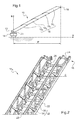
- a telescopic ladder 10 fixed on a support at a proximal end 12 of the support.
- the support may be a vehicle, for example of the fire protection and / or personal assistance type, or a trailer to be coupled to a vehicle or more generally any means for supporting and / or transporting the ladder 10
- a vehicle 14 on which is disposed the telescopic ladder 10 described below.
- the scale 10 comprises between the proximal end 12 and a distal end 16, first, second, third and fourth sections 18 1 , 18 2 , 18 3 and 18 4 .
- the proximal and distal nature of the ends of the scale 10 is defined relative to the vehicle 14.
- the number of sections is not limited to four. Indeed, the scale 10 may comprise a number of sections 18 greater than or equal to two.
- the sections 18 are movable relative to each other to allow the ladder 10 to be deployed or folded. In particular, the sections slide one inside the other so that the ladder 10 can be arranged in a fully retracted position. , in which the sections 18 are arranged one inside the other, in a fully deployed position (position shown in FIG. figure 1 ), wherein the sections 18 are substantially arranged end-to-end.
- the sections overlap one by one so that a covering portion is formed between each of the sections.
- the distal end 16 of the scale 10 corresponds to the end of the scale 10 opposite the proximal end 12 when the scale 10 is in the fully deployed position. In other words, the distal end 16 of the scale 10 coincides with the end of the fourth section 18 4 furthest from the proximal end 12.
- the vehicle 14 comprises a turret 20 for moving the scale 10 in rotation about a vertical axis B relative to the vehicle 14 and cylinders (not shown) for tilting the scale 10 around a axis perpendicular to the vertical axis B and to a horizontal axis A.
- the range P of the scale 10 is defined as the distance, projected on the horizontal axis A, separating the proximal and distal ends 12 and 16.
- the scale 10 To allow the scale 10 to have a maximum range P greater than a telescopic scale having sections made of a material of the same density, the section disposed at the proximal end 12 of the scale 10 - this is -to say, the first section 18 1 - is made of a material having a density greater than the density of the material in which is made at least another portion 18 of the scale 10.
- the second, third and / or fourth sections 18 2 , 18 3 and 18 4 are made, in whole or in part, in a material having a density less than the material used to make the first section 18 1 so that, on the one hand, the mass of the scale 10 is decreased and, secondly, the center of gravity of the scale 10 is closer to the proximal end 12 with respect to a scale in which the second, third and fourth sections 18 2 , 18 3 and 18 4 are made of a material having the same density as the material used for the first section 18 1 .
- the terms "in whole” and "in part” are detailed below.
- the combination of the decrease in the mass of the scale 10 and the approximation of the center of gravity towards the proximal end 12 makes it possible, while guaranteeing the physical integrity of the scale 10, to reduce the minimum inclination of the scale 10 so that the maximum range P of the scale 10 is increased.
- the inclination of the scale 10 is defined as the angle formed between the scale 10 and the horizontal axis A, in the plane formed by the horizontal and vertical axes A and B.
- the scale 10 may also be arranged so that the distal end 16 is disposed at an altitude below ground level, or more generally at an altitude lower than the altitude where the vehicle is located 14. The aforementioned advantages also apply to this last case.
- the materials used to make the sections 18 are, for example, in decreasing order of density, steel, titanium, aluminum, composite materials based on fiberglass or composite materials based on carbon fiber.
- the first section 18 1 is made of steel
- at least one of the other sections 18 is made for example in aluminum, titanium or composite materials of fiberglass or carbon.
- the material whose density is less than the material used for the first section 18 1 is a material whose density is less than 5, preferably 3, preferably 2.
- Density - referred to as relative density - is defined as the ratio between the density of this material and the density of water at 4 ° C, at atmospheric pressure.
- the material used for the fourth section 18 4 is a material based on carbon fiber. preferably at least in part based on so-called "high modulus" carbon fiber, that is to say carbon fibers having a Young's modulus greater than 400 GPa.
- the material used for the first, second and third sections 18 1 , 18 2 and 18 3 is steel or aluminum so that the manufacturing cost of the scale 10 is limited.
- the composite material based on carbon fibers used for the uprights 22 may comprise additional folds of carbon fibers oriented in different directions and forming localized extra thicknesses to allow the uprights 22 to withstand stresses exerted in directions different.
- the pieces are fixed together by gluing.
- rivets are also used in combination with bonding.
- the maximum P range P of the scale 10 while having a manufacturing cost of the limited scale, only the section disposed at the distal end 16 - the fourth section 18 4 - is made of carbon fiber base.
- the maximum P range can be increased by up to 10% compared to a known type of telescopic ladder made entirely of steel.
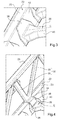
- the fourth section 18 4 comprises two uprights 22 extending parallel to one another to the distal end 16 of the scale 10.
- the fourth section 18 4 also comprises between the two uprights 22 a plurality of bars 26 allowing a user to advance along the fourth section 18 4 .
- the bars 26 extend substantially parallel to one another, each in a direction of extension C substantially perpendicular to the direction of extension of the uprights 22.
- the bars 26 comprise at each of their ends a fixing portion 38 of the bar 26 to an upright 22.
- This fixing portion 38 has a fixing surface of the bar 26 (not shown) intended to be brought into contact and fixed on a lateral surface 42 of an upright 22.
- Each bar 26 is formed, at a central portion 40, by a predetermined section perpendicular to the extension direction C of the bar 26, for example of rectangular shape.
- the bars 26 and the uprights 22 are arranged so that the area of the fixing surface of the bar 26 is greater than the area of the predetermined section at the of the central portion 40.
- the area of the predetermined section is defined by the area delimited by the outer envelope of the predetermined section.
- the attachment surface may be composed of one or more surfaces. In other words, the attachment surface may be continuous or discontinuous.
- the lateral surface 42 of the uprights 22 is inclined with respect to a plane perpendicular to the extension direction C of the bars 26.
- the lateral surface 42 is inclined at an angle of between 5 ° and 50 ° relative to the plane perpendicular to the extension direction C of a bar 26 This angle of inclination of the lateral surface 42 also corresponds to the angle formed between the fixing surface of the bar 26 and the plane perpendicular to the extension direction C of the bar 26.
- the combination of the flared shape of the ends of the bars 26 and the inclination of the lateral surfaces 42 allows the fourth section 18 4 to overcome the addition of reinforcing pieces - called struts - arranged between the bars 26 to guarantee the physical integrity of the known telescopic ladders, in particular in relation to the forces exerted by the side wind on the scale 10.
- the inclination of the lateral surfaces 42 also allows, for a constant distance between the two uprights 22 and a constant length of the surface on which the user bears, to increase the size of the section of the uprights 22 so that the uprights 22 have an increased mechanical strength.
- the fourth section 18 4 also comprises two rails 28 each extending along one of the two uprights 22, substantially parallel to the uprights 22.
- a plurality of support arms 30 - also called diagonals - are each fixed between the one of the uprights 22 and the rail 28 extending along this upright 22.
- the support arms 30 are arranged inclined relative to the extension direction of the uprights 22 and guardrails 28.
- each support arm 30 is formed together with another support arm 30 integrally to form a rail support 32 having substantially the shape of a V.
- Guardrail brackets 32 are arranged end to end between a post 22 and the rail 28 extending along this post 22 so that the bend of the V of a rail support 32 is fixed to the post 22 and the free ends of the V are fixed to the guardrail 28.
- each rail support 32 includes a base 34 for attaching the rail support 32 to an upper surface 23 of a post 22.
- the base 34 has an inclined portion 36 extending beyond the upper surface 23 of the post 22 to allow the base 34 to be also attached to the lateral surface 42 of the upright 22.
- the inclined portion 36 allows an increase in the contact area between the rail support 32 and the upright 22 so that the distribution of forces and therefore the mechanical strength of the fastener between the rail support 32 and the upright 22 are improved.
- the inclined portion 36 of the rail support 32 is suitable, when the base 34 of the railing support 32 is brought into contact with the upper surface 23 of an upright 22 and a bar 26 is disposed on the lateral surface 42 of the same upright 22 facing the railing support 32, to cover the fixing portion 38 of the bar 26.
- the inclined portion 36 is able to overlap the fixing portion 38 of the bar to allow the attachment of the inclined portion 36, the fixing portion 38 and the surface together. side of the amount.
- the inclined portion 36, the fixing portion 38 and the lateral surface 42 of the upright 22 can thus be riveted together to reinforce the attachment between the rail support 32, the bar 26 and the upright 22.
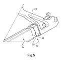
- the fourth section 18 4 also comprises at the distal end 16 an interface piece 24 for fixing a suspended nacelle (not shown) to the scale 10.
- the interface piece 24 is intended for be attached at one end to the scale 10 and, at another end, to a tilting device (not shown) on which is mounted the nacelle.
- the tilting device tilts the nacelle relative to the scale 10 so as to maintain the horizontality of the nacelle with respect to the ground.
- the interface piece 24 is fixed at the distal end 16 of the ladder 10 by sleeving, i.e. the pieces are threaded one inside the other.
- each upright 22 has at one end intended to be fixed to the interface piece 24 a portion of reduced section 25 so that a hollow portion 44 (shown in partial section) of the interface piece 24 in complementary form with the portion of reduced section 25 of the upright 22 can be housed and fit on the portion of reduced section 25.
- the guardrail 28 is fixed by sleeve to the interface piece 24, of similar to the attachment between the uprights 22 and the interface part 24. The fastening by sleeve allows a better distribution of the forces between the two parts fixed so that the fastener withstands greater stress than a fastener where the two parts are assembled end-to-end.
- a section 18 is made entirely of a material that at least the uprights 22, the rails 28, the bars 26 and the rail supports 32 are made of the same material.
- the expression "made entirely” does not exclude that the section comprises other parts, such as parts of assembly or fastening, made of another material, for example of higher density.
- a portion 18 is made in part of a material that at least one, but not all, of the uprights 22, the rails 28, the bars 26 and the supports of railing 32 are made of the same material.
- the fastening by sleeve between the interface piece 24 and the uprights 22 can be reversed, that is to say that the interface piece 24 comprises a portion whose section is reduced and the amounts 22 comprise a hollow portion complementarily shaped with the reduced section portion of the interface piece 24 so that the reduced section portion can fit and fit within the hollow portion.
- This fixing by reverse sleeve is also applicable to the attachment between the interface piece 24 and the guardrails 28.
- the section 18 which precedes it - the third section 18 3 - can also be made of a carbon fiber material for allow a greater reduction of the mass of the scale 10 and to bring the center of gravity closer to the scale 10 of the proximal end 12.
Landscapes
- Engineering & Computer Science (AREA)
- Mechanical Engineering (AREA)
- Ladders (AREA)
- Steps, Ramps, And Handrails (AREA)
- Fire-Extinguishing By Fire Departments, And Fire-Extinguishing Equipment And Control Thereof (AREA)
Abstract
La présente invention concerne une échelle (10) télescopique comprenant une extrémité proximale (12) adaptée à être fixée sur un support, l'échelle (10) comprenant entre l'extrémité proximale (12) et une extrémité distale (16) une pluralité de tronçons (18) déplaçables les uns par rapport aux autres pour déployer l'échelle (10), le tronçon (18 1 ) disposé au niveau de l'extrémité proximale (12) de l'échelle (10) étant réalisé dans un matériau ayant une densité supérieure à la densité du matériau dans lequel est réalisé au moins un autre tronçon (18) de l'échelle (10).The present invention relates to a telescopic ladder (10) comprising a proximal end (12) adapted to be fixed on a support, the ladder (10) comprising between the proximal end (12) and a distal end (16) a plurality of sections (18) displaceable relative to each other to deploy the ladder (10), the section (18 1) disposed at the proximal end (12) of the scale (10) being made of a material having a density greater than the density of the material in which at least one other section (18) of the scale (10) is made.
Description
La présente invention concerne une échelle télescopique comportant des tronçons d'échelle réalisés dans des matériaux de densités différentes. L'invention concerne également un véhicule sur lequel est fixée une telle échelle télescopique.The present invention relates to a telescopic ladder comprising ladder sections made of materials of different densities. The invention also relates to a vehicle on which is fixed such a telescopic ladder.
On entend par échelle télescopique une échelle composée de plusieurs tronçons déplaçables les uns par rapport aux autres de manière à faire varier la longueur totale de l'échelle par le déplacement des tronçons les uns par rapport aux autres.By telescopic ladder is meant a ladder composed of several sections that are movable relative to each other so as to vary the total length of the ladder by moving the sections relative to one another.
Un type d'échelle télescopique connu est une échelle s'étendant entre une extrémité proximale fixée sur un véhicule et une extrémité distale opposée à l'extrémité proximale, le caractère distal et proximal des extrémités étant défini par rapport au véhicule. L'extrémité distale est éloignée de l'extrémité proximale en faisant coulisser les tronçons les uns par rapport aux autres de manière à les disposer sensiblement bout à bout, tout en conservant une portion de recouvrement entre les tronçons. L'échelle peut généralement être déplacée en rotation suivant plusieurs axes de manière à faire varier davantage la position de l'extrémité distale de l'échelle. Ce type d'échelle télescopique est utilisé pour réaliser des travaux situés à des hauteurs ou profondeurs importantes, notamment pour l'aide à la personne dans un véhicule de protection incendie.One known type of telescopic ladder is a ladder extending between a proximal end attached to a vehicle and a distal end opposite the proximal end, the distal and proximal end being defined with respect to the vehicle. The distal end is remote from the proximal end by sliding the sections relative to each other so as to have them substantially end to end, while maintaining a portion of overlap between the sections. The scale can generally be rotated along a plurality of axes so as to further vary the position of the distal end of the scale. This type of telescopic ladder is used to carry out work at high heights or depths, particularly for personal assistance in a fire protection vehicle.
Dans ce type connu d'échelle télescopique l'ensemble des tronçons de l'échelle est fabriqué dans un même matériau, notamment l'acier ou l'aluminium.In this known type of telescopic ladder all sections of the ladder is made of the same material, including steel or aluminum.
De plus, un besoin particulier de ce type d'échelle télescopique est de pouvoir réaliser des travaux à des hauteurs et profondeurs peu importantes mais à une distance très éloignée du véhicule. En d'autres termes, la distance maximale séparant les extrémités proximale et distale, projetée sur un axe horizontal, doit être la plus importante possible. Cette distance est plus généralement appelée la portée maximale de l'échelle télescopique.In addition, a particular need for this type of telescopic ladder is to be able to perform work at low heights and depths but at a distance very far from the vehicle. In other words, the maximum distance separating the proximal and distal ends, projected on a horizontal axis, must be as large as possible. This distance is more generally called the maximum range of the telescopic ladder.
Toutefois, la portée maximale de ce type connu d'échelle télescopique n'est pas satisfaisante et ne permet donc pas de réaliser des travaux à des hauteurs et profondeurs peu importantes à une distance très éloignée du véhicule.However, the maximum range of this type of known telescopic ladder is not satisfactory and therefore does not allow to work at low heights and depths at a distance very far from the vehicle.
Il existe donc un besoin pour une échelle télescopique ayant une portée maximale augmentée.There is therefore a need for a telescopic ladder having an increased maximum reach.
A cette fin, la présente invention propose une échelle télescopique comprenant une extrémité proximale adaptée à être fixée sur un support, l'échelle comprenant entre l'extrémité proximale et une extrémité distale une pluralité de tronçons déplaçables les uns par rapport aux autres pour déployer l'échelle, le tronçon disposé au niveau de l'extrémité proximale de l'échelle étant réalisé dans un matériau ayant une densité supérieure à la densité du matériau dans lequel est réalisé au moins un autre tronçon de l'échelle.To this end, the present invention provides a telescopic ladder comprising a proximal end adapted to be fixed on a support, the ladder comprising between the proximal end and a distal end a plurality of sections movable relative to each other to deploy the scale, the stretch disposed at the level of the proximal end of the scale being made of a material having a density greater than the density of the material in which at least one other section of the scale is made.
Suivant des modes de réalisation préférés, l'invention comprend une ou plusieurs des caractéristiques suivantes :
- l'au moins un autre tronçon que le tronçon disposé au niveau de l'extrémité proximale est réalisé, en totalité ou en partie, dans un matériau dont la densité est inférieure à 5, de préférence inférieure à 3, de préférence inférieure à 2 ;
- l'au moins un autre tronçon que le tronçon disposé au niveau de l'extrémité proximale est réalisé, en totalité ou en partie, dans un matériau comportant des fibres de carbone ;
- l'au moins un autre tronçon que le tronçon disposé au niveau de l'extrémité proximale comprend deux montants, au moins un barreau apte à être fixé entre les montants, le barreau s'étendant suivant une direction d'extension et ayant au niveau d'une portion centrale du barreau une section prédéterminée perpendiculaire à la direction d'extension, le barreau comportant une surface de fixation du barreau à l'un des montants, la superficie de la surface de fixation étant supérieure à la superficie de la section prédéterminée ;
- les montants comportent chacun une surface latérale apte à recevoir la surface de fixation du barreau, la surface latérale d'au moins un montant étant inclinée par rapport à un plan perpendiculaire à la direction d'extension du barreau ;
- l'au moins un autre tronçon que le tronçon disposé au niveau de l'extrémité proximale comprend une pluralité de barreaux aptes à être fixés et à s'étendre entre les montants chacun suivant une direction d'extension, dans laquelle la surface latérale de fixation d'au moins un montant est inclinée par rapport à un plan perpendiculaire à la direction d'extension de chacun des barreaux ;
- les deux montants du tronçon comprennent une surface latérale inclinée par rapport à un plan perpendiculaire à la direction d'extension d'au moins un barreau, de préférence de chacun des barreaux ;
- au moins un barreau comporte une extrémité de forme évasée ;
- l'au moins un autre tronçon que le tronçon disposé au niveau de l'extrémité proximale comprend également deux rambardes s'étendant chacune le long de l'un des deux montants, une pluralité de bras de support des rambardes aptes à être fixés entre un montant et une rambarde s'étendant le long de ce montant, dans laquelle chaque bras de support est formé conjointement avec un autre bras de support de manière monobloc ;
- deux bras de support formés conjointement de manière monobloc forment un support de rambarde comportant une base apte à être mise au contact et fixée sur une surface supérieure d'un montant, la base comportant une portion inclinée apte à s'étendre au-delà de la surface supérieure du montant pour permettre à la base d'être également fixée sur la surface latérale de ce montant ;
- la portion inclinée du support de rambarde est apte, lorsque la base du support de rambarde est mise au contact de la surface supérieure d'un montant et qu'un barreau est disposé sur la surface latérale du montant en regard du support de rambarde, à recouvrir une portion de fixation du barreau ;
- la portion inclinée, la portion de fixation du barreau recouverte par la portion inclinée et la surface latérale du montant sont fixées ensemble, de préférence par rivetage ;
- le ou les barreaux et, le cas échéant, le support de rambarde sont fixés ensemble ou au montant par collage et/ou rivetage ;
- l'extrémité distale de l'échelle est définie lorsque l'échelle est totalement déployée, l'au moins un autre tronçon que le tronçon disposé au niveau de l'extrémité proximale étant celui des tronçons disposé au niveau de l'extrémité distale de l'échelle ;
- l'échelle est une échelle pour un véhicule de protection incendie et/ou d'aide à la personne, l'extrémité proximale de l'échelle étant apte à être fixée au véhicule et l'extrémité distale étant apte à être fixée à une nacelle suspendue.
- the at least one other portion than the section disposed at the proximal end is made, in whole or in part, in a material whose density is less than 5, preferably less than 3, preferably less than 2;
- the at least one other portion than the section disposed at the proximal end is made, in whole or in part, in a material comprising carbon fibers;
- the at least one other section than the section disposed at the proximal end comprises two uprights, at least one bar capable of being fixed between the uprights, the bar extending in a direction of extension and having at the level of a central portion of the bar a predetermined section perpendicular to the direction of extension, the bar having a securing surface of the bar to one of the uprights, the area of the attachment surface being greater than the area of the predetermined section;
- the uprights each comprise a lateral surface adapted to receive the fixing surface of the bar, the lateral surface of at least one upright being inclined with respect to a plane perpendicular to the direction of extension of the bar;
- the at least one other section than the section disposed at the proximal end comprises a plurality of bars able to be fixed and to extend between the uprights each in a direction of extension, in which the lateral fixing surface at least one amount is inclined relative to a plane perpendicular to the direction of extension of each of the bars;
- the two uprights of the section comprise a lateral surface inclined with respect to a plane perpendicular to the direction of extension of at least one bar, preferably each of the bars;
- at least one bar has a flared end;
- the at least one other section than the section disposed at the proximal end also comprises two rails each extending along one of the two uprights, a plurality of support arms brackets adapted to be fixed between a an upright and a rail extending therethrough, wherein each support arm is formed together with another support arm integrally;
- two integrally formed support arms form a rail support having a contactable base affixed to an upper surface of a post, the base having an inclined portion adapted to extend beyond the upper surface of the upright to allow the base to be also attached to the lateral surface of this upright;
- the inclined portion of the guardrail support is suitable, when the base of the railing support is brought into contact with the upper surface of a post and a rung is disposed on the lateral surface of the post opposite the rail support, to cover a fixing portion of the bar;
- the inclined portion, the fixing portion of the bar covered by the inclined portion and the lateral surface of the upright are fixed together, preferably by riveting;
- the bar (s) and, if applicable, the rail support are fixed together or to the post by bonding and / or riveting;
- the distal end of the scale is defined when the scale is fully extended, the at least one other section that the section disposed at the proximal end being that of the sections disposed at the distal end of the 'ladder ;
- the ladder is a ladder for a fire protection and / or personal assistance vehicle, the proximal end of the ladder being adapted to be fixed to the vehicle and the distal end being adapted to be attached to a pod suspended.
La présente invention concerne également un véhicule comprenant une telle échelle télescopique.The present invention also relates to a vehicle comprising such a telescopic ladder.
D'autres caractéristiques et avantages de l'invention apparaîtront à la lecture de la description qui suit d'un mode de réalisation préféré de l'invention, donné à titre d'exemple et en référence aux dessins annexés.
- La
figure 1 représente un schéma d'un véhicule supportant une échelle télescopique en position totalement déployée. - La
figure 2 représente un schéma d'un tronçon de l'échelle télescopique situé au niveau d'une extrémité distale de l'échelle télescopique. - La
figure 3 représente un schéma de la fixation entre un montant et un barreau de ce même tronçon. - La
figure 4 représente un schéma de la fixation entre un montant, un barreau, un support de rambarde et une rambarde de ce même tronçon précédent. - La
figure 5 représente un schéma de la fixation entre ce précédent tronçon et une pièce d'interface entre l'échelle télescopique et une nacelle suspendue, la pièce d'interface étant représentée en coupe partielle.
- The
figure 1 represents a diagram of a vehicle supporting a telescopic ladder in fully deployed position. - The
figure 2 represents a diagram of a section of the telescopic ladder located at a distal end of the telescopic ladder. - The
figure 3 represents a diagram of the fixing between an amount and a bar of this same section. - The
figure 4 represents a diagram of the attachment between an amount, a bar, a rail support and a guardrail of the same previous section. - The
figure 5 represents a diagram of the attachment between this previous section and an interface piece between the telescopic scale and a suspended nacelle, the interface part being shown in partial section.
En référence à la
L'échelle 10 comprend entre l'extrémité proximale 12 et une extrémité distale 16, un premier, un deuxième, un troisième et quatrième tronçons 181, 182, 183 et 184. Le caractère proximal et distal des extrémités de l'échelle 10 est défini par rapport au véhicule 14. Le nombre de tronçons n'est pas limité à quatre. En effet, l'échelle 10 peut comporter un nombre de tronçons 18 supérieur ou égal à deux. Les tronçons 18 sont déplaçables les uns par rapport aux autres pour permettre de déployer ou de reployer l'échelle 10. En particulier, les tronçons coulissent les uns dans les autres de sorte que l'échelle 10 peut être disposée d'une position totalement reployée, dans laquelle les tronçons 18 sont disposés les uns dans les autres, à une position totalement déployée (position représentée sur la
De plus, le véhicule 14 comprend une tourelle 20 permettant de déplacer l'échelle 10 en rotation autour d'un axe vertical B par rapport au véhicule 14 et des vérins (non représentés) permettant d'incliner l'échelle 10 autour d'un axe perpendiculaire à l'axe vertical B et à un axe horizontal A.In addition, the
La portée P de l'échelle 10 est définie comme étant la distance, projetée sur l'axe horizontal A, séparant les extrémités proximale et distale 12 et 16.The range P of the
Pour permettre à l'échelle 10 d'avoir une portée P maximale supérieure à une échelle télescopique ayant des tronçons réalisés dans un matériau de même densité, le tronçon disposé au niveau de l'extrémité proximale 12 de l'échelle 10 - c'est-à-dire le premier tronçon 181 - est réalisé dans un matériau ayant une densité supérieure à la densité du matériau dans lequel est réalisé au moins un autre tronçon 18 de l'échelle 10. En d'autres termes, les deuxième, troisième et/ou quatrième tronçons 182, 183 et 184 sont réalisés, en totalité ou en partie, dans un matériau ayant une densité inférieure au matériau utilisé pour réaliser le premier tronçon 181 de sorte que, d'une part, la masse de l'échelle 10 est diminuée et, d'autre part, le centre de gravité de l'échelle 10 est plus proche de l'extrémité proximale 12 par rapport à une échelle dans laquelle les deuxième, troisième et quatrième tronçons 182, 183 et 184 sont réalisés dans un matériau ayant la même densité que le matériau utilisé pour le premier tronçon 181. Les expressions « en totalité » et « en partie » sont détaillées plus bas. La combinaison de la diminution de la masse de l'échelle 10 et du rapprochement du centre de gravité vers l'extrémité proximale 12 permet, tout en garantissant l'intégrité physique de l'échelle 10, de diminuer l'inclinaison minimale de l'échelle 10 de sorte que la portée P maximale de l'échelle 10 est augmentée. En particulier, l'inclinaison de l'échelle 10 est définie comme l'angle formé entre l'échelle 10 et l'axe horizontal A, dans le plan formé par les axes horizontal et vertical A et B. En effet, l'échelle 10 peut être également disposée de sorte que l'extrémité distale 16 est disposée à une altitude inférieure au niveau du sol, ou plus généralement à une altitude inférieure à l'altitude où se situe le véhicule 14. Les avantages précités s'appliquent également à ce dernier cas.To allow the
Les matériaux utilisés pour réaliser les tronçons 18 sont par exemple, par ordre décroissant de densité, l'acier, le titane, l'aluminium, les matériaux composites à base de fibre de verre ou bien les matériaux composites à base de fibre de carbone. Ainsi, lorsque le premier tronçon 181 est réalisé en acier, au moins un des autres tronçons 18 est réalisé par exemple dans de l'aluminium, du titane ou des matériaux composites de fibre de verre ou de carbone.The materials used to make the
Pour améliorer davantage la portée P maximale de l'échelle 10, le matériau dont la densité est inférieure au matériau utilisé pour le premier tronçon 181 est un matériau dont la densité est inférieure à 5, de préférence à 3, de préférence à 2. La densité - appelée densité relative - est définie comme étant le rapport entre la masse volumique de ce matériau et la masse volumique de l'eau à 4°C, à la pression atmosphérique.To further improve the maximum range P of the
Pour obtenir un meilleur rapport entre la résistance mécanique de l'échelle 10 et le rapprochement du centre de gravité de l'échelle vers l'extrémité proximale 12, le matériau utilisé pour le quatrième tronçon 184 est un matériau à base de fibre de carbone, de préférence au moins en partie à base fibre de carbone dite à « haut module », c'est-à-dire des fibres de carbone ayant un module de Young supérieur à 400 GPa. Dans ce cas, le matériau utilisé pour les premier, deuxième et troisième tronçons 181, 182 et 183 est l'acier ou l'aluminium de sorte que le coût de fabrication de l'échelle 10 est limité.To obtain a better ratio between the mechanical resistance of the
De plus, le matériau composite à base de fibres de carbone utilisé pour les montants 22 peut comporter des plis supplémentaires de fibres de carbones orientées selon des directions différentes et formant des surépaisseurs localisées pour permettre aux montants 22 de résister à des sollicitations exercées dans des directions différentes.In addition, the composite material based on carbon fibers used for the
Pour permettre une fixation satisfaisante des pièces les unes entre les autres lorsque le matériau utilisé pour l'un au moins des deuxième, troisième et quatrième tronçons 182, 183 et 184 est un matériau composite, notamment à base de fibres de carbone, les pièces sont fixées ensemble par collage. Pour augmenter davantage la rigidité et renforcer les fixations entre les pièces, des rivets sont également utilisés en combinaison avec le collage.To allow a satisfactory fixing of the parts together when the material used for at least one of the second, third and
Pour augmenter la portée P maximale de l'échelle 10 tout en ayant un coût de fabrication de l'échelle 10 limité, seul le tronçon disposé au niveau de l'extrémité distale 16 - le quatrième tronçon 184 - est réalisé dans un matériau à base de fibre de carbone. Dans ce cas, la portée P maximale peut être augmentée à hauteur de 10% par rapport à un type connu d'échelle télescopique entièrement réalisé en acier.To increase the maximum range P of the
En référence à la
En référence à la
Pour améliorer la résistance mécanique de la fixation entre les barreaux 26 et les montants 22, les barreaux 26 et les montants 22 sont agencés de sorte que la superficie de la surface de fixation du barreau 26 est supérieure à la superficie de la section prédéterminée au niveau de la portion centrale 40. La superficie de la section prédéterminée est définie par l'aire délimitée par l'enveloppe externe de la section prédéterminée. Une augmentation de la surface de contact entre les barreaux 26 et les montants 22 permet une meilleure efficacité du collage et une meilleure répartition des efforts entre les barreaux 26 et les montants 22. De plus, l'amélioration de la résistance mécanique de chacune des fixations entre les barreaux 26 et les montants 22 permet une amélioration de la résistance mécanique globale du quatrième tronçon 184 et donc de l'échelle 10.To improve the mechanical strength of the fastening between the
Cette augmentation de la superficie de la surface de fixation est notamment obtenue par le fait que les barreaux 26 ont des extrémités de forme évasée. Ceci a pour effet d'augmenter la distance séparant la direction d'extension C du barreau 26 du bord extérieur du barreau 26 de sorte que la résistance mécanique du barreau 26 est améliorée, notamment face à une flexion du barreau 26. Toute autre forme permettant d'augmenter la distance séparant la direction d'extension C du barreau 26 du bord extérieur du barreau 26 peut convenir aux extrémités des barreaux 26. De plus, la surface de fixation peut être composée d'une ou plusieurs surfaces. En d'autres termes, la surface de fixation peut être continue ou discontinue.This increase in the surface area of the fastening surface is obtained in particular by the fact that the
Pour améliorer davantage la résistance mécanique de la fixation entre les barreaux 26 et les montants 22, notamment face à une torsion du quatrième tronçon 184 autour de son axe principale d'extension, la surface latérale 42 des montants 22 est inclinée par rapport à un plan perpendiculaire à la direction d'extension C des barreaux 26. En particulier, la surface latérale 42 est inclinée d'un angle compris entre 5° et 50° par rapport au plan perpendiculaire à la direction d'extension C d'un barreau 26. Cet angle d'inclinaison de la surface latérale 42 correspond également à l'angle formé entre la surface de fixation du barreau 26 et le plan perpendiculaire à la direction d'extension C du barreau 26.To further improve the mechanical strength of the fastening between the
De plus, la combinaison de la forme évasée des extrémités des barreaux 26 et de l'inclinaison des surfaces latérales 42 permet au quatrième tronçon 184 de s'affranchir de l'ajout de pièces de renfort - appelées bracons - disposées entre les barreaux 26 pour garantir l'intégrité physique des échelles télescopiques connues, notamment face aux efforts exercés par le vent latéral sur l'échelle 10. L'inclinaison des surfaces latérales 42 permet également, pour un entraxe constant entre les deux montants 22 et une longueur constante de la surface sur laquelle l'utilisateur prend appui, d'augmenter la taille de la section des montants 22 de sorte que les montants 22 ont une résistance mécanique accrue.In addition, the combination of the flared shape of the ends of the
En référence à nouveau à la
De manière à simplifier la conception des bras de support 30 et leur fixation avec les montants 22, chaque bras de support 30 est formé conjointement avec un autre bras de support 30 de manière monobloc pour former un support de rambarde 32 ayant sensiblement la forme d'un V. Les supports de rambardes 32 sont disposés bout à bout entre un montant 22 et la rambarde 28 s'étendant le long de ce montant 22 de sorte que le coude du V d'un support de rambarde 32 est fixé au montant 22 et les extrémités libres du V sont fixées à la rambarde 28.In order to simplify the design of the
En référence à la
Pour améliorer la résistance mécanique à la fois de la fixation entre un barreau 26 et un montant 22 et à la fois de la fixation entre un support de rambarde 32 et un montant 22, la portion inclinée 36 du support de rambarde 32 est apte, lorsque la base 34 du support 32 de rambarde est mise au contact de la surface supérieure 23 d'un montant 22 et qu'un barreau 26 est disposé sur la surface latérale 42 du même montant 22 en regard du support de rambarde 32, à recouvrir la portion de fixation 38 du barreau 26. En d'autres termes, la portion inclinée 36 est apte à chevaucher la portion de fixation 38 du barreau pour permettre la fixation ensemble de la portion inclinée 36, de la portion de fixation 38 et de la surface latérale du montant. La portion inclinée 36, la portion de fixation 38 et la surface latérale 42 du montant 22 peuvent ainsi être rivetées ensemble pour renforcer la fixation entre le support de rambarde 32, le barreau 26 et le montant 22.To improve the mechanical strength of both the fixing between a
En référence à la
Par ailleurs, on entend par le fait qu'un tronçon 18 est réalisé en totalité dans un matériau qu'au moins les montants 22, les rambardes 28, les barreaux 26 et les supports de rambarde 32 sont réalisés dans ce même matériau. En d'autres termes, l'expression « réalisé en totalité » n'exclue pas que le tronçon comporte d'autres pièces, telles que des pièces d'assemblage ou de fixation, réalisées dans un autre matériau, par exemple de densité supérieure.Furthermore, it is meant that a
De plus, on entend par le fait qu'un tronçon 18 est réalisé en partie dans un matériau qu'au moins l'un, mais pas l'intégralité, parmi les montants 22, les rambardes 28, les barreaux 26 et les supports de rambarde 32 sont réalisés dans ce même matériau.In addition, it is meant that a
Bien entendu, la présente invention n'est pas limitée aux exemples et au mode de réalisation décrits et représentés, mais elle est susceptible de nombreuses variantes accessibles à l'homme de l'art.Of course, the present invention is not limited to the examples and to the embodiment described and shown, but it is capable of numerous variants accessible to those skilled in the art.
A titre d'exemple, la fixation par manchonnage entre la pièce d'interface 24 et les montants 22 peut être inversée, c'est-à-dire que la pièce d'interface 24 comporte une portion dont la section est réduite et les montants 22 comportent une portion creuse en complémentarité de forme avec la portion de section réduite de la pièce d'interface 24 de sorte que la portion de section réduite peut se loger et s'ajuster à l'intérieur de la portion creuse. Cette fixation par manchonnage inversée est également applicable à la fixation entre la pièce d'interface 24 et les rambardes 28.By way of example, the fastening by sleeve between the
Par ailleurs, en plus du tronçon disposé au niveau de l'extrémité distale 16 - le quatrième tronçon 184, le tronçon 18 qui le précède - le troisième tronçon 183 - peut également être réalisé dans un matériau à base de fibre de carbone pour permettre une réduction plus importante de la masse de l'échelle 10 et pour rapprocher davantage le centre de gravité de l'échelle 10 de l'extrémité proximale 12.Furthermore, in addition to the section disposed at the distal end 16 - the
Claims (16)
dans laquelle la surface latérale (42) de fixation d'au moins un montant (22) est inclinée par rapport à un plan perpendiculaire à la direction d'extension (C) de chacun des barreaux (26).Scale (10) according to claim 5, wherein the at least one other section (18 2 , 18 3 , 18 4 ) that the section (18 1 ) disposed at the proximal end (12) comprises a plurality of bars (26) adapted to be fixed and extend between the uprights (22) each in an extension direction (C),
wherein the lateral surface (42) for fixing at least one upright (22) is inclined with respect to a plane perpendicular to the extension direction (C) of each of the bars (26).
Applications Claiming Priority (1)
| Application Number | Priority Date | Filing Date | Title |
|---|---|---|---|
| FR1457321A FR3024489B1 (en) | 2014-07-29 | 2014-07-29 | TELESCOPIC SCALE COMPRISING SCALE TRONCONS OF DIFFERENT DENSITY |
Publications (1)
| Publication Number | Publication Date |
|---|---|
| EP2980347A1 true EP2980347A1 (en) | 2016-02-03 |
Family
ID=51726746
Family Applications (1)
| Application Number | Title | Priority Date | Filing Date |
|---|---|---|---|
| EP15178548.2A Withdrawn EP2980347A1 (en) | 2014-07-29 | 2015-07-27 | Telescoping ladder comprising ladder sections having different densities |
Country Status (8)
| Country | Link |
|---|---|
| US (1) | US20160032649A1 (en) |
| EP (1) | EP2980347A1 (en) |
| JP (1) | JP2016031016A (en) |
| KR (1) | KR20160014555A (en) |
| CN (1) | CN105317367A (en) |
| FR (1) | FR3024489B1 (en) |
| HK (1) | HK1217220A1 (en) |
| RU (1) | RU2015131162A (en) |
Families Citing this family (3)
| Publication number | Priority date | Publication date | Assignee | Title |
|---|---|---|---|---|
| KR102134922B1 (en) * | 2018-12-14 | 2020-07-17 | 이준호 | Small fire truck for lifesaving |
| CN110259370B (en) * | 2019-06-20 | 2023-12-08 | 中交二航局第四工程有限公司 | Ladder stand with self-adaptive adjustment inclination angle and stepping kept horizontal all the time |
| RU200222U1 (en) * | 2020-03-13 | 2020-10-13 | Игорь Юрьевич Девятловский | Sliding ladder |
Citations (5)
| Publication number | Priority date | Publication date | Assignee | Title |
|---|---|---|---|---|
| EP0000344A1 (en) * | 1977-07-06 | 1979-01-24 | Abru Aluminium Limited | Improvements in or relating to ladders |
| FR2473614A1 (en) * | 1980-01-14 | 1981-07-17 | Kinziger Claude | Two-piece trailer-mounted pivotable extending ladder - is supported by bottom piece of compound sheet metal trough section braced by rung core rods |
| US4371055A (en) * | 1980-11-07 | 1983-02-01 | Little Giant Industries, Inc. | Method of manufacturing a fiberglass ladder |
| US20060032705A1 (en) * | 2004-08-16 | 2006-02-16 | Isham William R | Lightweight composite ladder rail having supplemental reinforcement in regions subject to greater structural stress |
| US20140102830A1 (en) * | 2012-10-16 | 2014-04-17 | Nasir U. Ahmed | Fiberglass Reinforced Plastic Lightweight Heavy-Duty Ladder and Method of Making Same |
Family Cites Families (17)
| Publication number | Priority date | Publication date | Assignee | Title |
|---|---|---|---|---|
| US2582520A (en) * | 1949-06-04 | 1952-01-15 | Mccabe Powers Auto Body Co | Ladder |
| FR2448028A1 (en) * | 1979-01-30 | 1980-08-29 | Camiva | TELESCOPIC LADDER STRUCTURE |
| US4540095A (en) * | 1984-02-23 | 1985-09-10 | Federal Motors, Inc. | Counterweighted aerial trailer |
| DE3625298A1 (en) * | 1986-04-26 | 1987-10-29 | Iveco Magirus | LADDER ARRANGEMENT WITH EXTENDABLE LADDER PARTS, ESPECIALLY FIREFIGHTER LADDERS |
| DE3640944A1 (en) * | 1986-11-29 | 1988-06-09 | Metz Feuerwehrgeraete Gmbh | Aerial ladder |
| US4852690A (en) * | 1988-12-05 | 1989-08-01 | Simon Ladder Towers, Inc. | Aerial ladder tower with pretensioned truss members |
| US6342861B1 (en) * | 1989-04-26 | 2002-01-29 | Daniel A. Packard | Loop antenna assembly |
| US5211245A (en) * | 1991-07-01 | 1993-05-18 | Crash Rescue Equipment Service, Inc. | Vehicle mounted aerial lift |
| GB2387373A (en) * | 2002-04-12 | 2003-10-15 | Bamford Excavators Ltd | Composite boom for a load handling machine |
| US7201255B1 (en) * | 2004-01-23 | 2007-04-10 | Kreikemeier Robert D | Apparatus and method of forming a corrosion resistant coating on a ladder |
| CN201050290Y (en) * | 2007-04-16 | 2008-04-23 | 王贞禄 | Plastic ladder structure |
| DE102008013203A1 (en) * | 2008-03-08 | 2009-09-17 | Terex-Demag Gmbh | Boom for end-loading of loads, boom assembly with at least two such cantilevers and method of making such a boom |
| CN201276966Y (en) * | 2008-08-07 | 2009-07-22 | 杨雅娟 | Extension ladder |
| JP5543418B2 (en) * | 2011-10-13 | 2014-07-09 | 株式会社小松製作所 | Movable ladder device for work vehicle |
| ITMI20131680A1 (en) * | 2013-10-11 | 2015-04-12 | Cifa Spa | AUXILIARY DEVICE FOR A CRANE AND CRANE INCLUDING SUCH AUXILIARY DEVICE |
| CN203614016U (en) * | 2013-12-24 | 2014-05-28 | 威海广泰空港设备股份有限公司 | Scaling ladder telescopic mechanism for firefighting truck |
| US9410659B2 (en) * | 2014-02-10 | 2016-08-09 | The Boeing Company | Automated mobile boom system for crawling robots |
-
2014
- 2014-07-29 FR FR1457321A patent/FR3024489B1/en not_active Expired - Fee Related
-
2015
- 2015-07-27 EP EP15178548.2A patent/EP2980347A1/en not_active Withdrawn
- 2015-07-27 RU RU2015131162A patent/RU2015131162A/en not_active Application Discontinuation
- 2015-07-27 JP JP2015147414A patent/JP2016031016A/en active Pending
- 2015-07-28 US US14/810,834 patent/US20160032649A1/en not_active Abandoned
- 2015-07-29 CN CN201510455433.0A patent/CN105317367A/en active Pending
- 2015-07-29 KR KR1020150107108A patent/KR20160014555A/en unknown
-
2016
- 2016-05-06 HK HK16105180.1A patent/HK1217220A1/en unknown
Patent Citations (5)
| Publication number | Priority date | Publication date | Assignee | Title |
|---|---|---|---|---|
| EP0000344A1 (en) * | 1977-07-06 | 1979-01-24 | Abru Aluminium Limited | Improvements in or relating to ladders |
| FR2473614A1 (en) * | 1980-01-14 | 1981-07-17 | Kinziger Claude | Two-piece trailer-mounted pivotable extending ladder - is supported by bottom piece of compound sheet metal trough section braced by rung core rods |
| US4371055A (en) * | 1980-11-07 | 1983-02-01 | Little Giant Industries, Inc. | Method of manufacturing a fiberglass ladder |
| US20060032705A1 (en) * | 2004-08-16 | 2006-02-16 | Isham William R | Lightweight composite ladder rail having supplemental reinforcement in regions subject to greater structural stress |
| US20140102830A1 (en) * | 2012-10-16 | 2014-04-17 | Nasir U. Ahmed | Fiberglass Reinforced Plastic Lightweight Heavy-Duty Ladder and Method of Making Same |
Also Published As
| Publication number | Publication date |
|---|---|
| RU2015131162A3 (en) | 2019-01-24 |
| US20160032649A1 (en) | 2016-02-04 |
| HK1217220A1 (en) | 2016-12-30 |
| FR3024489A1 (en) | 2016-02-05 |
| KR20160014555A (en) | 2016-02-11 |
| RU2015131162A (en) | 2017-02-02 |
| CN105317367A (en) | 2016-02-10 |
| FR3024489B1 (en) | 2018-08-10 |
| JP2016031016A (en) | 2016-03-07 |
Similar Documents
| Publication | Publication Date | Title |
|---|---|---|
| EP1614622B1 (en) | Aircraft cockpit floor | |
| CA2500494C (en) | Longeron for aircraft and centre-wing section equipped with such a longeron | |
| FR2818611A1 (en) | FOLDABLE BICYCLE | |
| EP3174791B1 (en) | Tube having a hybrid-type structure, in particular for an aircraft seat | |
| FR2523072A1 (en) | AIRCRAFT PROVIDED WITH A MULTIPLE OVERLAPPING SUSPENSION STRUCTURE | |
| FR2827235A1 (en) | Automobile bumper beam comprise base longitudinal element and additional element which fit into each other by means of locking lugs in one element penetrating holes in other element | |
| EP2980347A1 (en) | Telescoping ladder comprising ladder sections having different densities | |
| FR2749561A1 (en) | LANDING TRAIN WITH SKATES FOR HELICOPTER | |
| WO1997036520A1 (en) | Chair consisting of interlocking elements | |
| EP0774032B1 (en) | Adjustable staircase | |
| FR2941480A1 (en) | Stud for safety balustrade on acroterion of terrace of building, has movable arm provided with bar whose length allows bar to be supported on vertical face of acroterion and arranged in bottom of external edge of acroterion | |
| FR2922830A1 (en) | DOSSIER COMPRISING AN INTEGRATED SAFETY BELT. | |
| CA2970373C (en) | Device to protect against falling objects | |
| WO1995007033A1 (en) | Protective sheet consisting of plates joined by rings and aprons obtained using this type of layer | |
| WO2006123027A1 (en) | Extending, folding ladder comprising a single central post | |
| EP3767049A1 (en) | Pergola comprising a support structure and a foldable shading element | |
| EP0151591B1 (en) | Rigging particularly for sailing board | |
| EP0814219A1 (en) | Rolling light-weight work-platform | |
| FR2992607A1 (en) | Rigid rear covering device for backrest of seat of automobile, has elastic element arranged in transverse manner from external surface to opposite internal surface in multiple locations of device to produce multiple elastic element segments | |
| EP1647648B1 (en) | Connecting device between a corner post and two filler panels for a railing | |
| EP1143103A1 (en) | Transportable tree stand | |
| EP0026713A2 (en) | Motorcycle frame with strengthening of the steering column | |
| EP2501876B1 (en) | Railing formed of a set of ready-to-assemble detached parts | |
| EP4110683A1 (en) | Vehicle having a structure that exhibits a third load path between the cradle and a front side rail | |
| EP0323940A1 (en) | Wind screen |
Legal Events
| Date | Code | Title | Description |
|---|---|---|---|
| PUAI | Public reference made under article 153(3) epc to a published international application that has entered the european phase |
Free format text: ORIGINAL CODE: 0009012 |
|
| AK | Designated contracting states |
Kind code of ref document: A1 Designated state(s): AL AT BE BG CH CY CZ DE DK EE ES FI FR GB GR HR HU IE IS IT LI LT LU LV MC MK MT NL NO PL PT RO RS SE SI SK SM TR |
|
| AX | Request for extension of the european patent |
Extension state: BA ME |
|
| 17P | Request for examination filed |
Effective date: 20160727 |
|
| RBV | Designated contracting states (corrected) |
Designated state(s): AL AT BE BG CH CY CZ DE DK EE ES FI FR GB GR HR HU IE IS IT LI LT LU LV MC MK MT NL NO PL PT RO RS SE SI SK SM TR |
|
| REG | Reference to a national code |
Ref country code: HK Ref legal event code: DE Ref document number: 1217220 Country of ref document: HK |
|
| STAA | Information on the status of an ep patent application or granted ep patent |
Free format text: STATUS: THE APPLICATION IS DEEMED TO BE WITHDRAWN |
|
| 18D | Application deemed to be withdrawn |
Effective date: 20200201 |
|
| REG | Reference to a national code |
Ref country code: HK Ref legal event code: WD Ref document number: 1217220 Country of ref document: HK |