JP2016031016A - Telescopic ladder comprising ladder parts different in specific gravity - Google Patents
Telescopic ladder comprising ladder parts different in specific gravity Download PDFInfo
- Publication number
- JP2016031016A JP2016031016A JP2015147414A JP2015147414A JP2016031016A JP 2016031016 A JP2016031016 A JP 2016031016A JP 2015147414 A JP2015147414 A JP 2015147414A JP 2015147414 A JP2015147414 A JP 2015147414A JP 2016031016 A JP2016031016 A JP 2016031016A
- Authority
- JP
- Japan
- Prior art keywords
- ladder
- telescopic
- proximal end
- telescopic ladder
- fixed
- Prior art date
- Legal status (The legal status is an assumption and is not a legal conclusion. Google has not performed a legal analysis and makes no representation as to the accuracy of the status listed.)
- Pending
Links
- 230000005484 gravity Effects 0.000 title claims abstract description 29
- 239000000463 material Substances 0.000 claims abstract description 44
- 229920000049 Carbon (fiber) Polymers 0.000 claims description 11
- 239000004917 carbon fiber Substances 0.000 claims description 11
- 239000000725 suspension Substances 0.000 claims description 4
- 239000000758 substrate Substances 0.000 abstract 1
- 239000002131 composite material Substances 0.000 description 7
- 229910000831 Steel Inorganic materials 0.000 description 5
- 230000003247 decreasing effect Effects 0.000 description 5
- 239000010959 steel Substances 0.000 description 5
- XAGFODPZIPBFFR-UHFFFAOYSA-N aluminium Chemical compound [Al] XAGFODPZIPBFFR-UHFFFAOYSA-N 0.000 description 4
- 229910052782 aluminium Inorganic materials 0.000 description 4
- VNWKTOKETHGBQD-UHFFFAOYSA-N methane Chemical compound C VNWKTOKETHGBQD-UHFFFAOYSA-N 0.000 description 4
- RTAQQCXQSZGOHL-UHFFFAOYSA-N Titanium Chemical compound [Ti] RTAQQCXQSZGOHL-UHFFFAOYSA-N 0.000 description 2
- 230000000295 complement effect Effects 0.000 description 2
- 230000014509 gene expression Effects 0.000 description 2
- 239000003365 glass fiber Substances 0.000 description 2
- 238000004519 manufacturing process Methods 0.000 description 2
- 229910052719 titanium Inorganic materials 0.000 description 2
- 239000010936 titanium Substances 0.000 description 2
- OKTJSMMVPCPJKN-UHFFFAOYSA-N Carbon Chemical compound [C] OKTJSMMVPCPJKN-UHFFFAOYSA-N 0.000 description 1
- 238000004026 adhesive bonding Methods 0.000 description 1
- 230000000712 assembly Effects 0.000 description 1
- 238000000429 assembly Methods 0.000 description 1
- 238000005452 bending Methods 0.000 description 1
- 229910052799 carbon Inorganic materials 0.000 description 1
- 230000000694 effects Effects 0.000 description 1
- 239000000835 fiber Substances 0.000 description 1
- 230000010354 integration Effects 0.000 description 1
- 230000003014 reinforcing effect Effects 0.000 description 1
- XLYOFNOQVPJJNP-UHFFFAOYSA-N water Substances O XLYOFNOQVPJJNP-UHFFFAOYSA-N 0.000 description 1
Images


Classifications
-
- E—FIXED CONSTRUCTIONS
- E06—DOORS, WINDOWS, SHUTTERS, OR ROLLER BLINDS IN GENERAL; LADDERS
- E06C—LADDERS
- E06C5/00—Ladders characterised by being mounted on undercarriages or vehicles Securing ladders on vehicles
- E06C5/02—Ladders characterised by being mounted on undercarriages or vehicles Securing ladders on vehicles with rigid longitudinal members
- E06C5/04—Ladders characterised by being mounted on undercarriages or vehicles Securing ladders on vehicles with rigid longitudinal members capable of being elevated or extended ; Fastening means during transport, e.g. mechanical, hydraulic
-
- E—FIXED CONSTRUCTIONS
- E06—DOORS, WINDOWS, SHUTTERS, OR ROLLER BLINDS IN GENERAL; LADDERS
- E06C—LADDERS
- E06C7/00—Component parts, supporting parts, or accessories
- E06C7/18—Devices for preventing persons from falling
- E06C7/181—Additional gripping devices, e.g. handrails
- E06C7/183—Additional gripping devices, e.g. handrails situated along the ladder
-
- E—FIXED CONSTRUCTIONS
- E06—DOORS, WINDOWS, SHUTTERS, OR ROLLER BLINDS IN GENERAL; LADDERS
- E06C—LADDERS
- E06C1/00—Ladders in general
- E06C1/02—Ladders in general with rigid longitudinal member or members
- E06C1/04—Ladders for resting against objects, e.g. walls poles, trees
- E06C1/08—Ladders for resting against objects, e.g. walls poles, trees multi-part
- E06C1/12—Ladders for resting against objects, e.g. walls poles, trees multi-part extensible, e.g. telescopic
-
- E—FIXED CONSTRUCTIONS
- E06—DOORS, WINDOWS, SHUTTERS, OR ROLLER BLINDS IN GENERAL; LADDERS
- E06C—LADDERS
- E06C7/00—Component parts, supporting parts, or accessories
- E06C7/08—Special construction of longitudinal members, or rungs or other treads
Landscapes
- Engineering & Computer Science (AREA)
- Mechanical Engineering (AREA)
- Ladders (AREA)
- Steps, Ramps, And Handrails (AREA)
- Fire-Extinguishing By Fire Departments, And Fire-Extinguishing Equipment And Control Thereof (AREA)
Abstract
Description
本発明は、異なる比重の材料によって構成されたはしご部分を備える、伸縮式はしごに関する。本発明は、さらに、そのような伸縮式はしごが固定された車両に関する。 The present invention relates to a telescopic ladder including a ladder portion made of materials having different specific gravities. The invention further relates to a vehicle to which such a telescopic ladder is fixed.
伸縮式はしごとは、互いに変位可能である複数のはしご部分から構成されていて、それらはしご部分が互いに変位することにより、当該はしごの全長が変化するはしごのことを意味する。 The telescopic ladder is composed of a plurality of ladder portions that are displaceable with each other, and the ladder portions are displaced from each other so that the total length of the ladder is changed.
既知の種類の伸縮式はしごは、車両に固定される近位側端部と近位側端部の反対側にある遠位側端部との間に延びて(端部が近位側であるか遠位側であるかについては、車両を基準にして決められる。)、はしご部分同士を互いにスライドさせて遠位側端部を近位側端部から遠ざかるように動かすと、はしご部分間である程度の重複部分を維持しながら、はしご部分同士が端部と端部とでほぼ互いに突き合わされるようにして位置決めされるはしごである。一般的に、そのようなはしごは、当該はしごの遠位側端部の位置をさらに変更できるように、複数の軸に沿って回転運動することが可能である。この種類の伸縮式はしごは、かなりの高さ又は深さの位置で仕事を行うのに使用され、特に、消防車両で人間を救出するのに使用される。 A known type of telescopic ladder extends between a proximal end fixed to the vehicle and a distal end opposite the proximal end (the end is proximal) Or the distal side is determined with reference to the vehicle.) When sliding the ladder parts together and moving the distal end away from the proximal end, between the ladder parts The ladder is positioned in such a manner that the ladder portions are substantially abutted with each other at the end portions while maintaining a certain overlap portion. In general, such a ladder is capable of rotational movement along multiple axes so that the position of the distal end of the ladder can be further altered. This type of telescopic ladder is used to perform work at significant heights or depths, and is particularly used to rescue humans in fire fighting vehicles.
この既知の種類の伸縮式はしごでは、当該はしごの全てのはしご部分が、同一の材料、特には、鋼又はアルミニウムによって形成されている。 In this known type of telescopic ladder, all ladder parts of the ladder are made of the same material, in particular steel or aluminum.
この種類の伸縮式はしごには、出来る限り低い位置及び出来る限り浅い位置で且つ車両からかなり離れた距離で、仕事を実行できるものが特に求められる。言い換えれば、近位側端部と遠位側端部とを隔てる最大距離が、水平軸上に投影した際に、可能な限り長くならなければならない。このような投影後の距離は、伸縮式はしごの最大リーチと一般的に称される。 This type of telescopic ladder is particularly required to be able to perform work at as low a position as possible and as shallow as possible and at a considerable distance from the vehicle. In other words, the maximum distance separating the proximal and distal ends should be as long as possible when projected onto the horizontal axis. Such a projected distance is commonly referred to as the maximum reach of the telescopic ladder.
しかし、前述した既知の種類の伸縮式はしごでは、最大リーチが満足のいくものでなく、低い位置や浅い位置で且つ車両からかなり離れた距離で仕事を実行することができない。 However, with the known types of telescopic ladders described above, the maximum reach is not satisfactory, and work cannot be performed at low or shallow positions and at a considerable distance from the vehicle.
したがって、より大きな最大リーチを有する伸縮式はしごが所望されている。 Accordingly, a telescopic ladder having a greater maximum reach is desired.
この目的のために、本発明は、伸縮式はしごであって、支持体に固定されるように構成された近位側端部を有し、前記近位側端部と遠位側端部との間に、当該はしごを伸長するために互いに変位可能である複数のはしご部分を備えており、当該はしごの前記近位側端部の位置配されるはしご部分を構成する材料の比重が、当該はしごのそれ以外の少なくとも1つの他のはしご部分を形成する材料の比重よりも大きい、伸縮式はしごを提案する。 To this end, the present invention is a telescopic ladder having a proximal end configured to be secured to a support, the proximal end and the distal end. A plurality of ladder portions that are displaceable relative to each other to extend the ladder, and the specific gravity of the material constituting the ladder portion positioned at the proximal end of the ladder is A retractable ladder is proposed that is greater than the specific gravity of the material forming at least one other ladder portion of the ladder.
本発明は、好ましい実施形態において、下記の少なくとも1つの構成を備える:
−前記近位側端部の位置に配されるはしご部分以外の少なくとも1つの他のはしご部分が、全体的に又は部分的に、比重が5未満の材料、好ましくは比重が3未満の材料、より好ましくは比重が2未満の材料によって構成されている;
−前記近位側端部の位置に配されるはしご部分以外の少なくとも1つの他のはしご部分が、全体的に又は部分的に、炭素繊維を含む材料によって構成されている;
−前記近位側端部の位置に配されるはしご部分以外の少なくとも1つの他のはしご部分が、2つの支柱、および前記支柱間に固定可能な少なくとも1つの踏み桟であって、延在方向に延在し、その中央部位の位置に前記延在方向と直交する所定の断面を有し、さらに、前記支柱の一つとの固定面を有しており、当該固定面の表面積が前記所定の断面の断面積よりも大きい、少なくとも1つの踏み桟を含む;
−前記支柱のそれぞれが、前記踏み桟の前記固定面を受けることが可能な側面を有しており、少なくとも1つの支柱の当該側面が、前記踏み桟の前記延在方向と直交する平面に対して傾斜している;
−前記近位側端部の位置に配されるはしご部分以外の少なくとも1つの他のはしご部分が、前記支柱間にそれぞれの延在方向に延在するように固定可能な複数の踏み桟を含み、少なくとも1つの支柱の固定する前記側面が、これらの踏み桟のそれぞれの前記延在方向と直交する平面に対して傾斜している;
−前記はしご部分の前記2つの支柱が、少なくとも1つの踏み桟の前記延在方向、好ましくは前記踏み桟のそれぞれの前記延在方向と直交する平面に対して傾斜した側面を有している;
−少なくとも1つの踏み桟が、張出し形状の端部を有している;
−前記近位側端部の位置に配されるはしご部分以外の少なくとも1つの他のはしご部分が、さらに、前記2つの支柱の一つに沿ってそれぞれが延びる、2つの手摺り、および前記手摺りの複数の支持アームであって、支柱と当該支柱に沿って延びる手摺りとの間に固定可能な支持アームを含み、支持アームのそれぞれが別の支持アームと一体的に接続されて形成されている;
−一体的に接続されて形成された2つの支持アームが、支柱の上面に当接して固定可能なベースを有する、手摺り支持部材を形成しており、当該ベースが、その支柱の上面を越えて延出してその支柱の前記側面に固定可能な傾斜部位を有している;
−前記手摺り支持部材の前記傾斜部位が、当該手摺り支持部材の前記ベースが支柱の上面に当接する際および踏み桟が当該手摺り支持部材に面するようにしてその支柱の側面に配置される際に、この踏み桟の固定部位を覆うことが可能である;
−前記傾斜部位、前記踏み桟のうち、当該傾斜部位によって覆われた前記固定部位、および前記支柱の前記側面が、好ましくはリベット留めにより、互いに固定されている;
−前記少なくとも1つの踏み桟、および任意で前記手摺り支持部材が、接着および/またはリベット留めで、互いに又は前記支柱に固定されている;
−当該はしごの前記遠位側端部が、当該はしごが完全に伸長されることによって現れるものであり、前記近位側端部の位置に配されるはしご部分以外の少なくとも1つの他のはしご部分が、当該はしごの前記遠位側端部の位置に配されるはしご部分となる;および
−当該はしごが、消防車両および/または救命車両用のはしごであり、当該はしごの前記近位側端部が、その車両に固定可能であり、前記遠位側端部が、懸架かご体に固定可能である。
In a preferred embodiment, the present invention comprises at least one of the following configurations:
-At least one other ladder part other than the ladder part arranged at the position of the proximal end, in whole or in part, is a material having a specific gravity of less than 5, preferably a material having a specific gravity of less than 3; More preferably, it is constituted by a material having a specific gravity of less than 2.
The at least one other ladder part other than the ladder part arranged at the position of the proximal end is constituted in whole or in part by a material comprising carbon fibers;
The at least one other ladder part other than the ladder part arranged at the position of the proximal end is two struts and at least one step bar that can be fixed between the struts, and extending direction And has a predetermined cross section perpendicular to the extending direction at the position of the central portion, and further has a fixing surface with one of the columns, and the surface area of the fixing surface is the predetermined surface Including at least one step bar greater than the cross-sectional area of the cross-section;
Each of the columns has a side surface capable of receiving the fixed surface of the step bar, and the side surface of the at least one column is relative to a plane perpendicular to the extending direction of the step frame; Tilted;
-At least one other ladder portion other than the ladder portion arranged at the position of the proximal end portion includes a plurality of step bars that can be fixed so as to extend in the respective extending directions between the columns. The side surface to which at least one column is fixed is inclined with respect to a plane perpendicular to the extending direction of each of the step bars;
The two struts of the ladder part have side surfaces that are inclined with respect to the extending direction of at least one step bar, preferably with respect to a plane perpendicular to the extending direction of each of the step bars;
-At least one step bar has an overhanging end;
The at least one other ladder portion other than the ladder portion disposed at the position of the proximal end portion further includes two handrails each extending along one of the two struts, and the hand A plurality of sliding support arms, including a support arm that can be fixed between a support column and a handrail extending along the support column, each of the support arms being integrally connected to another support arm. ing;
-Two support arms formed integrally connected form a handrail support member having a base that can be fixed in contact with the upper surface of the column, and the base exceeds the upper surface of the column. An inclined portion that extends and can be fixed to the side surface of the column;
The inclined portion of the handrail support member is disposed on a side surface of the support rail when the base of the handrail support member is in contact with the upper surface of the support column and the tread bar faces the handrail support member; It is possible to cover the fixed part of the stepping stake when
The fixed part covered by the inclined part of the inclined part, the step bar and the side surface of the column are fixed to each other, preferably by riveting;
The at least one step bar, and optionally the handrail support member, are secured to each other or to the post by gluing and / or riveting;
-The distal end of the ladder is manifested by full extension of the ladder and at least one other ladder part other than the ladder part located at the position of the proximal end A ladder portion disposed at the distal end of the ladder; and-the ladder is a ladder for a fire and / or life vehicle and the proximal end of the ladder Can be fixed to the vehicle, and the distal end can be fixed to a suspension car body.
本発明は、さらに、このような伸縮式はしごを備える車両に関する。 The invention further relates to a vehicle comprising such an extendable ladder.
本発明のさらなる特徴および利点は、添付の図面を参照しながら行う、本発明の好ましい実施形態についての以下の説明から明らかになる。なお、後述の実施形態はあくまでも例示に過ぎない点に留意されたい。 Further features and advantages of the present invention will become apparent from the following description of preferred embodiments of the invention, made with reference to the accompanying drawings. It should be noted that the embodiments described below are merely examples.
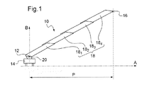
図1に、支持体に対して近位側端部12の位置で固定された伸縮式はしご10を示す。そのような支持体は、車両であり得て、例えば、消防系および/または救急系の車両、車両に繋がれたトレーラー等であってもよく、より一般的には、はしご10を支持および/または運搬するどのような手段であってもよい。これに関連して、本発明は、さらに、後述する伸縮式はしご10が設置された車両14を提案する。
FIG. 1 shows a
はしご10は、近位側端部12と遠位側端部16との間に、第1のはしご部分181、第2のはしご部分182、第3のはしご部分183および第4のはしご部分184を備える。はしご10の端部が近位側であるか遠位側であるかについては、車両14を基準にして決められる。はしご部分の数は4つでなくてもよい。事実、はしご10のはしご部分18の数は、二つ以上であればどのような数であってもよい。はしご部分18は、はしご10を伸長又は収縮(reploying)するために互いに変位可能である。具体的に述べると、はしご部分18が互いの内部に配されて完全に収縮された状態から、はしご部分同士を互いにスライドさせることにより、はしご10を、端部と端部とがほぼ互いに突き合わされて完全に伸長した状態(図1に示す状態)に設定することができる。より具体的に述べると、完全に伸長した状態では、一つ一つのはしご部分が重複することで、各はしご部分間に重複部分が形成される。はしご10の遠位側端部16は、当該はしご10が完全に伸長した状態での、近位側端部12とは反対側の端部に相当する。すなわち、近位側端部12から最も離れる端部である、第4のはしご部分184の端部が、はしご10の遠位側端部16を兼ねる。
車両14は、はしご10を当該車両14に対して垂直軸B周りに回転させる旋回台20と、はしご10を垂直軸Bと水平軸Aとに直交する軸を中心として傾動させるジャッキ(図示せず)とを備える。
The
はしご10のリーチPは、近位側端部12と遠位側端部16とを隔てる距離を、水平軸A上に投影した距離として定義される。
The reach P of the
はしご10は、同じ比重の材料によって構成された複数のはしご部分を備える伸縮式はしごよりも最大リーチPを長くするために、当該はしご10の近位側端部12の位置に配されるはしご部分(すなわち、第1のはしご部分181)を構成する材料の比重が、当該はしご10のそれ以外の少なくとも1つの他のはしご部分18を形成する材料の比重よりも大きく設定されている。言い換えるならば、第2のはしご部分182および/または第3のはしご部分183および/または第4のはしご部分184が、全体的に又は部分的に、第1のはしご部分181を製作するのに使用される材料よりも小さい比重の材料によって構成されている。これにより、はしご10の質量が減少すると共に、当該はしご10の重心が、第2、第3および第4のはしご部分182,183,184が第1のはしご部分181を製作するのに使用される材料と同じ比重の材料によって構成されたはしごと比べて、近位側端部12に近付く。「全体的」および「部分的」という表現については、後で詳述する。はしご10の質量が減少することと重心が近位側端部12に近付くことの共同作用により、はしご10の物理的一体性を確保しながら、はしご10の最小起梯角度を減少させて当該はしご10の最大リーチPを増加させることができる。具体的に述べると、はしご10の起梯角度とは、水平軸Aと垂直軸Bとによって形成される平面上での、はしご10と水平軸Aとの間の角度として定義される。事実、はしご10は、遠位側端部16が地面よりも低い高度に配されるように位置決めすることも可能であり、より一般的には、はしご10を、遠位側端部16が車両14の高度よりも低い高度に配されるように位置決めすることが可能である。前述した利点は後者の場合にも当てはまる。
The
はしご部分18を製作するのに使用可能な材料の例として、比重の大きい順に、鋼、チタン、アルミニウム、ガラス繊維に基づく複合材料、炭素繊維に基づく複合材料等が挙げられる。よって、第1のはしご部分181が鋼によって構成される場合、それ以外の少なくとも1つの他のはしご部分18が、例えばアルミニウム、チタン、ガラス繊維又は炭素繊維の複合材料等によって構成されることになる。
Examples of materials that can be used to fabricate the
はしご10の最大リーチPをさらに増加させるには、第1のはしご部分181を製作するのに使用される材料よりも小さい比重の前記材料を、比重が5未満の材料、好ましくは比重が3未満の材料、より好ましくは比重が2未満の材料とする。比重(相対密度とも称される)は、対象の材料の密度と水の(温度=4℃、大気圧での)密度との比として定義される。
To further increase the maximum reach P of the
はしご10の機械的抵抗と近位側端部12への重心の近付きとのバランスをさらに優れたものにするには、第4のはしご部分184に用いる材料を、炭素繊維に基づく材料、好ましくは「ハイモジュラス」と称される炭素繊維に少なくとも部分的に基づいた材料とする。ここで、「ハイモジュラス」とは、ヤング率が400GPaを超える炭素繊維のことを意味する。この場合、第1、第2および第3のはしご部分181,182,183に用いる材料を鋼またはアルミニウムとすることにより、はしご10の製造コストを抑えることができる。
To excellent further the balance between the center of gravity of the closer to the mechanical resistance and the
また、炭素繊維に基づく複合材料を支柱22に使用する際には、その複合材料において、炭素繊維を異なる方向の向きで追加で重ねることにより、局所的に余剰肉厚部を形成することができる。これにより、支柱22は、様々な方向の応力に耐えることができる。
Moreover, when using the composite material based on carbon fiber for the support |
第2、第3および第4のはしご部分182,183,184のうちの少なくとも1つのはしご部分に用いられる材料が、複合材料(特に、炭素繊維に基づく複合材料)である場合に、部材士の固定を満足のいくものにするには、当該部材同士を接着で固定する。剛性をさらに増大させると共に部材間の結合性をさらに増強するには、接着に加えてリベットを併用する。
If the second, the material used for the at least one Tsunohashigo portion of the third and
はしご10の最大リーチPを伸ばしつつ、当該はしご10の製造コストを抑えるには、遠位側端部16の位置に配されるはしご部分(すなわち、第4のはしご部分184)のみを、炭素繊維に基づく材料によって構成されるものとする。この構成によれば、全体が鋼によって構成された既知の種類の伸縮式はしごに比べて、高さに対する最大リーチPを10%増やすことができる。
In order to reduce the manufacturing cost of the
図2を参照する。第4のはしご部分184は、2つの支柱22を含む。これら2つの支柱22は、はしご10の遠位側端部16まで互いに平行に延びている。第4のはしご部分184は、さらに、これら2つの支柱22間に、はしごの使用者が当該第4のはしご部分184に沿って前方に進むことを可能にする複数の踏み桟26を含む。これらの踏み桟26は、互いに実質的に平行であり、かつ、支柱22の延び方向と実質的に直交するそれぞれの延在方向Cに沿って延在している。
Please refer to FIG.
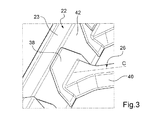
図3を参照する。踏み桟26は、各端部に、支柱22との固定部位38を有する。この固定部位38は、その踏み桟26のうち、支柱22の側面42に当接して固定される固定面(図示せず)を含む。それぞれの踏み桟26には、中央部位40の位置に、当該踏み桟26の延在方向Cと直交する所定の断面、例えば直方形状の断面が形成されている。
Please refer to FIG. The
踏み桟26と支柱22との取付部の機械的抵抗を増大させるには、これら踏み桟26および支柱22を、当該踏み桟26の前記固定面の表面積が前記中央部位40の位置での前記所定の断面の断面積よりも大きくなるように配置する。前記所定の断面の断面積は、当該所定の断面の外殻によって画定される面積として定義される。踏み桟26と支柱22との接触面積を増加させることにより、踏み桟26と支柱22との付着効果および踏み桟26と支柱22との間の力分散を向上させることができる。また、踏み桟26と支柱22との各々の取付部の機械的抵抗が増大することにより、第4のはしご部分184全体の機械的抵抗、したがって、はしご10全体の機械的抵抗を増大させることができる。
In order to increase the mechanical resistance of the attachment portion between the
特に、このように前記固定面の表面積を増加させるには、踏み桟26を、張出し形状の端部を有するものとする。これにより、踏み桟26の延在方向Cと当該踏み桟26の外縁とを隔てる距離が増えるので、踏み桟26の機械的抵抗(特に、踏み桟26が撓みに曝される際の機械的抵抗)が増大するという効果が得られる。張出し形状以外にも、踏み桟26の延在方向Cと当該踏み桟26の外縁とを隔てる距離を増やすものであれば、どのような形状も、踏み桟26の端部の形状として適用可能である。また、前記固定面は、1つの表面で構成されたものであってもよいし、複数の表面で構成されたものであってもよい。すなわち、前記固定面は、連続面であってもよいし、不連続面であってもよい。
In particular, in order to increase the surface area of the fixed surface in this manner, the
踏み桟26と支柱22との取付部の機械的抵抗(特に、第4のはしご部分184が自身の主要な延在軸心を中心とした捻れに曝される際の機械的抵抗)をさらに増大させるには、支柱22の側面42を、踏み桟26の延在方向Cと直交する平面に対して傾斜させる。具体的には、側面42を、踏み桟26の延在方向Cと直交する平面に対して5°〜50°の角度で傾斜させる。このような側面42の傾斜角度は、その踏み桟26の前記固定面と当該踏み桟26の延在方向Cと直交する平面との間の角度にも相当する。
Mechanical resistance of the mounting portion of the stepping
また、踏み桟26の端部の前記張出し形状と支柱22の側面42の前記傾きとの組合せにより、既知の伸縮式はしごのように、物理的統合性(特に、横風によってはしご10に力が加わる際の物理的統合性)を確保するために踏み桟26間に補強部材(「ブレース」と称される)を追加で設置せずともよくなる。また、2つの支柱22間の間隔及びはしごの使用者を支持する面状体の長さは一定のままで支柱22の側面42を傾斜させることにより、その支柱22の断面の大きさが増加し、当該支柱22の機械的抵抗が増大する。
In addition, the combination of the protruding shape of the end of the
再び図2を参照する。第4のはしご部分184は、さらに、2つの支柱22の一つに沿ってそれぞれが延びる、支柱22に実質的に平行な2つの手摺り28を含む。支柱22の一つと当該支柱22に沿って延びる手摺り28との間には、複数の支持アーム30(「ダイアゴナル」とも称される)が固定されている。これら支持アーム30は、支柱22及び手摺り28の延び方向に対して傾いて配置されている。
Refer to FIG. 2 again.
支持アーム30の設計および当該支持アーム30と支柱22との取付部の設計を簡単にするには、支持アーム30のそれぞれを、別の支持アーム30と一体的に接続されて形成されて実質的にV字形状の手摺り支持部材32を形成するものとする。手摺り支持部材32は、その端ら端まで、支柱22と当該支柱22に沿って延びる手摺り28との間に配置されて、そのV字における肘部が当該支柱22に固定されると共に、そのV字における自由端部が当該手摺り28に固定される。
In order to simplify the design of the
図4を参照する。手摺り支持部材32のそれぞれは、当該手摺り支持部材32を支柱22の上面23に固定するベース34を有する。ベース34は、支柱22の上面23を越えて延出してその支柱22の側面42に固定可能な傾斜部位36を有している。傾斜部位36により、手摺り支持部材32と支柱22との接触面積が増加するので、これら手摺り支持部材32と支柱22との間の力分散が向上し、これにより、これら手摺り支持部材32と支柱22との取付部の機械的抵抗を増大させることができる。
Please refer to FIG. Each of the
踏み桟26と支柱22との取付部の機械的抵抗および手摺り支持部材32と支柱22との取付部の機械的抵抗を増大させるには、手摺り支持部材32の傾斜部位36を、当該手摺り支持部材32のベース34が支柱22の上面23に当接し、かつ、踏み桟26が、当該手摺り支持部材32に面しているその支柱22の側面42に配置された状態で、この踏み桟26の固定部位38を覆うことが可能なものとする。すなわち、傾斜部位36を、踏み桟の固定部位38に重ね合わせることで当該傾斜部位36とその固定部位38と支柱の側面とを互いに連接させることが可能なものとする。これら傾斜部位36、固定部位38および支柱22の側面42は、互いにリベット留めされてもよい。これにより、手摺り支持部材32と踏み桟26と支柱22との取付部分を強化することができる。
In order to increase the mechanical resistance of the attachment portion between the
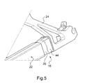
図5を参照する。第4のはしご部分184は、さらに、遠位側端部16の位置に、懸架かご体(図示せず)をはしご10に固定するためのインターフェース部材24を含む。具体的に述べると、インターフェース部材24は、一端ではしご10に固定されると共に、前記かご体が取り付けられる傾け装置(図示せず)に他端で固定されるように構成されている。この傾け装置は、前記かご体を、地面に対して水平状態に維持しながらはしご10に対して傾ける。インターフェース部材24は、スリーブ接続、すなわち、接続に関わる部材同士を互いに嵌め込むことにより、はしご10の遠位側端部16の位置に固定されている。具体的に述べると、支柱22のそれぞれが、インターフェース部材24と固定する端位置において断面積減少部位25を有しており、インターフェース部材24のうち、当該支柱22のこのような断面積減少部位25の形状と相補的な中空部位44(一部のみが図示されている)を嵌めて、当該断面積減少部位25に合致させることができる。手摺り28も、支柱22とインターフェース部材24との取付部と同様に、スリーブ接続によってインターフェース部材24と固定されている。スリーブ接続による取付部は、固定された2つの部材間の力分散を向上させることができるので、2つの部材を端部と端部とを突き合わせるようにして組み付けられてなる取付部よりも大きな応力に耐えることができる。
Please refer to FIG. The
はしご部分18が全体的に所与の材料によって構成されるということは、明らかに、少なくとも支柱22、手摺り28、踏み桟26および手摺り支持部材32が互いに同じ材料によって構成されるということである。換言すれば、「全体的に…構成される」という表現は、そのはしご部分が、別の材料(例えば、より高い密度の材料など)によって構成された組立体、取付部材などの他の部材を含む場合を排除しないとも言える。
The fact that the
はしご部分18が部分的に所与の材料によって構成されるということは、明らかに、支柱22、手摺り28、踏み桟26および手摺り支持部材32のうちの少なくとも1つは互いに同じ材料によって構成されるものの、それらの全てが互いに同じ材料によって構成されてはいないということである。
Obviously, the
当然ながら、本発明は、説明・図示した例や実施形態に限定されるものではなく、当業者にとって想到可能な数多くの変形形態を取り得る。 Of course, the present invention is not limited to the examples and embodiments described and illustrated, and can take many variations that can be conceived by those skilled in the art.
一例として、インターフェース部材24と支柱22とのスリーブ接続による取付部を、逆の関係にすることが考えられる。すなわち、インターフェース部材24が断面積減少部位を有するものとし、支柱22が、そのインターフェース部材24の断面積減少部位の形状と相補的な中空部位を有するものとすることで、当該断面積減少部位を嵌めて、その中空部位に合致させる構成が考えられる。このような逆のスリーブ接続による取付部は、インターフェース部材24と手摺り28との取付部にも適用可能である。
As an example, it is conceivable that the attachment portion by the sleeve connection between the
また、遠位側端部16の位置に配されるはしご部分(すなわち、第4のはしご部分184)に加えて、その一つ前のはしご部分18(すなわち、第3のはしご部分183)についても、炭素繊維に基づく材料によって構成されるものとすることで、はしご10の質量をさらに減少させることができると共に、当該はしご10の重心を近位側端部12にさらに近付けることができる。
Further, in addition to the ladder portion (that is, the fourth ladder portion 18 4 ) arranged at the position of the
Claims (16)
前記近位側端部(12)と遠位側端部(16)との間に、前記はしご(10)を伸長するために互いに変位可能である複数のはしご部分(18)を備えており、
前記はしご(10)の前記近位側端部(12)の位置に配されるはしご部分(181)を構成する材料の比重が、前記はしご(10)の少なくとも1つの他のはしご部分(18)を形成する材料の比重よりも大きい、伸縮式はしご(10)。 A telescopic ladder (10) configured such that the proximal end (12) is secured to the support,
Between the proximal end (12) and the distal end (16), a plurality of ladder portions (18) that are displaceable relative to each other to extend the ladder (10);
The specific gravity of the material constituting the ladder portion (18 1 ) disposed at the position of the proximal end (12) of the ladder (10) is such that at least one other ladder portion (18 Telescopic ladder (10), which is greater than the specific gravity of the material forming.
−2つの支柱(22)、および
−前記支柱(22)間に固定可能な少なくとも1つの踏み桟(26)であって、延在方向(C)に延在し、前記踏み桟の中央部位(40)の位置に前記延在方向(C)と直交する所定の断面を有し、さらに、前記支柱(22)の一つとの固定面を有しており、前記固定面の面積が前記所定の断面の面積よりも大きい、少なくとも1つの踏み桟(26)、
を含む、伸縮式はしご(10)。 Telescopic ladder (10) according to any one of claims 1 to 3, wherein said at least one other than the ladder portion (18 1 ) arranged at the position of said proximal end (12). The ladder part (18 2 , 18 3 , 18 4 )
-Two struts (22), and-at least one step bar (26) fixable between the struts (22), extending in the extending direction (C), 40) has a predetermined cross section orthogonal to the extending direction (C), and further has a fixing surface with one of the columns (22), and the area of the fixing surface is the predetermined At least one step bar (26), which is larger than the area of the cross section,
Telescopic ladder (10) including
−前記2つの支柱(22)の各々に沿ってそれぞれ延びる、2つの手摺り(28)、および
−前記手摺り(28)の複数の支持アーム(30)であって、支柱(22)と前記支柱(22)に沿って延びる手摺り(28)との間に固定可能な支持アーム(30)、
を含み、支持アーム(30)のそれぞれが別の支持アーム(30)と一体的に接続されて形成されている、伸縮式はしご(10)。 Telescopic ladder (10) according to any one of claims 4 to 8, wherein said at least one other than the ladder portion (18 1 ) arranged at the position of said proximal end (12). The ladder portion (18 2 , 18 3 , 18 4 )
-Two handrails (28) extending along each of the two struts (22), and-a plurality of support arms (30) of the handrail (28), comprising the strut (22) and the A support arm (30) fixable between a handrail (28) extending along the support post (22);
A telescopic ladder (10), wherein each of the support arms (30) is formed integrally connected with another support arm (30).
Applications Claiming Priority (2)
| Application Number | Priority Date | Filing Date | Title |
|---|---|---|---|
| FR1457321 | 2014-07-29 | ||
| FR1457321A FR3024489B1 (en) | 2014-07-29 | 2014-07-29 | TELESCOPIC SCALE COMPRISING SCALE TRONCONS OF DIFFERENT DENSITY |
Publications (2)
| Publication Number | Publication Date |
|---|---|
| JP2016031016A true JP2016031016A (en) | 2016-03-07 |
| JP2016031016A5 JP2016031016A5 (en) | 2018-08-16 |
Family
ID=51726746
Family Applications (1)
| Application Number | Title | Priority Date | Filing Date |
|---|---|---|---|
| JP2015147414A Pending JP2016031016A (en) | 2014-07-29 | 2015-07-27 | Telescopic ladder comprising ladder parts different in specific gravity |
Country Status (8)
| Country | Link |
|---|---|
| US (1) | US20160032649A1 (en) |
| EP (1) | EP2980347A1 (en) |
| JP (1) | JP2016031016A (en) |
| KR (1) | KR20160014555A (en) |
| CN (1) | CN105317367A (en) |
| FR (1) | FR3024489B1 (en) |
| HK (1) | HK1217220A1 (en) |
| RU (1) | RU2015131162A (en) |
Cited By (1)
| Publication number | Priority date | Publication date | Assignee | Title |
|---|---|---|---|---|
| KR20200074305A (en) * | 2018-12-14 | 2020-06-25 | 이준호 | Small fire truck for lifesaving |
Families Citing this family (2)
| Publication number | Priority date | Publication date | Assignee | Title |
|---|---|---|---|---|
| CN110259370B (en) * | 2019-06-20 | 2023-12-08 | 中交二航局第四工程有限公司 | Ladder stand with self-adaptive adjustment inclination angle and stepping kept horizontal all the time |
| RU200222U1 (en) * | 2020-03-13 | 2020-10-13 | Игорь Юрьевич Девятловский | Sliding ladder |
Family Cites Families (22)
| Publication number | Priority date | Publication date | Assignee | Title |
|---|---|---|---|---|
| US2582520A (en) * | 1949-06-04 | 1952-01-15 | Mccabe Powers Auto Body Co | Ladder |
| GB1595202A (en) * | 1977-07-06 | 1981-08-12 | Abru Aluminium Ltd | Ladders |
| FR2448028A1 (en) * | 1979-01-30 | 1980-08-29 | Camiva | TELESCOPIC LADDER STRUCTURE |
| FR2473614A1 (en) * | 1980-01-14 | 1981-07-17 | Kinziger Claude | Two-piece trailer-mounted pivotable extending ladder - is supported by bottom piece of compound sheet metal trough section braced by rung core rods |
| US4371055A (en) * | 1980-11-07 | 1983-02-01 | Little Giant Industries, Inc. | Method of manufacturing a fiberglass ladder |
| US4540095A (en) * | 1984-02-23 | 1985-09-10 | Federal Motors, Inc. | Counterweighted aerial trailer |
| DE3625298A1 (en) * | 1986-04-26 | 1987-10-29 | Iveco Magirus | LADDER ARRANGEMENT WITH EXTENDABLE LADDER PARTS, ESPECIALLY FIREFIGHTER LADDERS |
| DE3640944A1 (en) * | 1986-11-29 | 1988-06-09 | Metz Feuerwehrgeraete Gmbh | Aerial ladder |
| US4852690A (en) * | 1988-12-05 | 1989-08-01 | Simon Ladder Towers, Inc. | Aerial ladder tower with pretensioned truss members |
| US6342861B1 (en) * | 1989-04-26 | 2002-01-29 | Daniel A. Packard | Loop antenna assembly |
| US5211245A (en) * | 1991-07-01 | 1993-05-18 | Crash Rescue Equipment Service, Inc. | Vehicle mounted aerial lift |
| GB2387373A (en) * | 2002-04-12 | 2003-10-15 | Bamford Excavators Ltd | Composite boom for a load handling machine |
| US7201255B1 (en) * | 2004-01-23 | 2007-04-10 | Kreikemeier Robert D | Apparatus and method of forming a corrosion resistant coating on a ladder |
| US20060032705A1 (en) * | 2004-08-16 | 2006-02-16 | Isham William R | Lightweight composite ladder rail having supplemental reinforcement in regions subject to greater structural stress |
| CN201050290Y (en) * | 2007-04-16 | 2008-04-23 | 王贞禄 | Plastic ladder structure |
| DE102008013203A1 (en) * | 2008-03-08 | 2009-09-17 | Terex-Demag Gmbh | Boom for end-loading of loads, boom assembly with at least two such cantilevers and method of making such a boom |
| CN201276966Y (en) * | 2008-08-07 | 2009-07-22 | 杨雅娟 | Extension ladder |
| JP5543418B2 (en) * | 2011-10-13 | 2014-07-09 | 株式会社小松製作所 | Movable ladder device for work vehicle |
| US9168701B2 (en) * | 2012-10-16 | 2015-10-27 | Abss Manufacturing Co., Inc. | Fiberglass reinforced plastic lightweight heavy-duty ladder and method of making same |
| ITMI20131680A1 (en) * | 2013-10-11 | 2015-04-12 | Cifa Spa | AUXILIARY DEVICE FOR A CRANE AND CRANE INCLUDING SUCH AUXILIARY DEVICE |
| CN203614016U (en) * | 2013-12-24 | 2014-05-28 | 威海广泰空港设备股份有限公司 | Scaling ladder telescopic mechanism for firefighting truck |
| US9410659B2 (en) * | 2014-02-10 | 2016-08-09 | The Boeing Company | Automated mobile boom system for crawling robots |
-
2014
- 2014-07-29 FR FR1457321A patent/FR3024489B1/en not_active Expired - Fee Related
-
2015
- 2015-07-27 EP EP15178548.2A patent/EP2980347A1/en not_active Withdrawn
- 2015-07-27 JP JP2015147414A patent/JP2016031016A/en active Pending
- 2015-07-27 RU RU2015131162A patent/RU2015131162A/en not_active Application Discontinuation
- 2015-07-28 US US14/810,834 patent/US20160032649A1/en not_active Abandoned
- 2015-07-29 CN CN201510455433.0A patent/CN105317367A/en active Pending
- 2015-07-29 KR KR1020150107108A patent/KR20160014555A/en unknown
-
2016
- 2016-05-06 HK HK16105180.1A patent/HK1217220A1/en unknown
Cited By (2)
| Publication number | Priority date | Publication date | Assignee | Title |
|---|---|---|---|---|
| KR20200074305A (en) * | 2018-12-14 | 2020-06-25 | 이준호 | Small fire truck for lifesaving |
| KR102134922B1 (en) * | 2018-12-14 | 2020-07-17 | 이준호 | Small fire truck for lifesaving |
Also Published As
| Publication number | Publication date |
|---|---|
| HK1217220A1 (en) | 2016-12-30 |
| FR3024489B1 (en) | 2018-08-10 |
| RU2015131162A (en) | 2017-02-02 |
| US20160032649A1 (en) | 2016-02-04 |
| CN105317367A (en) | 2016-02-10 |
| FR3024489A1 (en) | 2016-02-05 |
| KR20160014555A (en) | 2016-02-11 |
| EP2980347A1 (en) | 2016-02-03 |
| RU2015131162A3 (en) | 2019-01-24 |
Similar Documents
| Publication | Publication Date | Title |
|---|---|---|
| JP5642209B2 (en) | Temporary handrail mounting jig | |
| JP2016031016A (en) | Telescopic ladder comprising ladder parts different in specific gravity | |
| JP6313847B2 (en) | Seat leg assembly for passenger seat, frame for passenger seat and passenger seat | |
| JP2016118016A5 (en) | ||
| CN104024046B (en) | Seat backrest frame structure | |
| ITMI971354A1 (en) | LANDING TROLLEY FOR HELICOPTER | |
| JP2018502237A (en) | Vertically oriented ladder device to allow climbers to adopt improved climbing posture during use | |
| JP2010089586A (en) | Multi-stage sliding slope apparatus for vehicle | |
| JP2016031016A5 (en) | ||
| CN105863231A (en) | Scaffold convenient to move | |
| CN204660035U (en) | A kind of transporation by plane and inspection platform | |
| JP3208681U (en) | Ladder | |
| CN109050974B (en) | Safety barrier for transferring planet car ramp | |
| JP6658632B2 (en) | Automatic warehouse with ladder and stacker crane with ladder attached | |
| KR102640943B1 (en) | CFRP bonded ladder for agricultural machinery | |
| US20240125177A1 (en) | Gas spring supported, bushing guided caster assembly for rolling ladders and ladders having same | |
| JP7263079B2 (en) | boarding bridge | |
| KR101141666B1 (en) | Boom structure for high place works car | |
| JP2000265768A (en) | Extensible ladder | |
| KR20200035725A (en) | Foldable ladder assembly | |
| JP5347592B2 (en) | Building stairs | |
| FI12076U1 (en) | Arrangement for forming a support platform | |
| JP2015024768A (en) | Stair device used in passenger boarding bridge or gangway ladder | |
| SE1050847A1 (en) | Ice hockey rink with transparent protective equipment | |
| KR20230003790A (en) | CFRP bonded ladder |
Legal Events
| Date | Code | Title | Description |
|---|---|---|---|
| A521 | Written amendment |
Free format text: JAPANESE INTERMEDIATE CODE: A523 Effective date: 20180705 |
|
| A621 | Written request for application examination |
Free format text: JAPANESE INTERMEDIATE CODE: A621 Effective date: 20180705 |
|
| A977 | Report on retrieval |
Free format text: JAPANESE INTERMEDIATE CODE: A971007 Effective date: 20190717 |
|
| A131 | Notification of reasons for refusal |
Free format text: JAPANESE INTERMEDIATE CODE: A131 Effective date: 20190806 |
|
| A02 | Decision of refusal |
Free format text: JAPANESE INTERMEDIATE CODE: A02 Effective date: 20200303 |