EP3279399B1 - Fahrbahnübergang für strassenbauwerke - Google Patents
Fahrbahnübergang für strassenbauwerke Download PDFInfo
- Publication number
- EP3279399B1 EP3279399B1 EP16182742.3A EP16182742A EP3279399B1 EP 3279399 B1 EP3279399 B1 EP 3279399B1 EP 16182742 A EP16182742 A EP 16182742A EP 3279399 B1 EP3279399 B1 EP 3279399B1
- Authority
- EP
- European Patent Office
- Prior art keywords
- tooth
- base
- teeth
- flexible blade
- blade
- Prior art date
- Legal status (The legal status is an assumption and is not a legal conclusion. Google has not performed a legal analysis and makes no representation as to the accuracy of the status listed.)
- Active
Links
Images


Classifications
-
- E—FIXED CONSTRUCTIONS
- E01—CONSTRUCTION OF ROADS, RAILWAYS, OR BRIDGES
- E01D—CONSTRUCTION OF BRIDGES, ELEVATED ROADWAYS OR VIADUCTS; ASSEMBLY OF BRIDGES
- E01D19/00—Structural or constructional details of bridges
- E01D19/06—Arrangement, construction or bridging of expansion joints
Definitions
- the present invention relates to expansion joints for road structures, also commonly called road joints, intended to ensure the continuity of the road between consecutive sections of road structures such as bridge decks.
- joints of this kind consist of two elongated metal elements fixed by anchoring means on two parts of the road structure facing one of the other along a slot, and between which is disposed a deformable seal assembly arranged to seal when the metal elements move relative to each other, especially when their spacing varies due to movement relative parts of the works to which they are connected.
- a roadway joint consists of elements having a row of teeth forming a running surface extending in the direction of the other element, the two rows of triangularly shaped teeth being able to interlock when the two elements are brought together .
- This type of seal has the advantage of ensuring a continuity of the surface, by nesting the teeth together.
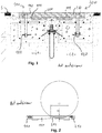
- the figure 1 shows an example of a road joint according to the prior art. It is intended to connect two parts of pavement C1, C2 separated by a slot F comprising two sets 100, 200 respectively anchored in one or other of the pavement parts on either side of the slot.
- Each set 100, 200 comprises a comb 110, 210 having a series of teeth 111, 211, the teeth of one of the combs 110, 210 being embedded in the teeth of the other comb to ensure the continuity of the upper surface of the comb.
- Each comb 110, 210 is fixed by screwing in inserts 120 embedded in concrete.
- the invention aims to provide a roadway seal with characteristics adapted to the passage of narrow wheels.
- the invention relates to a road joint for connecting two parts of pavement separated by a slot comprising two sets respectively anchored in one or the other part of the roadway on either side of the slot, each set comprising a comb having a series of teeth, the teeth of one of the combs being nested in the teeth of the other comb to ensure the continuity of the upper surface of the roadway when the parts of the road are struggling between a close position in which the slot is the narrowest and a spaced apart position in which the slot is widest, the seal being characterized in that it comprises retractable means adapted to fill, at least partially, the spaces between a first and second adjacent teeth of the same comb and a third tooth of the other comb inserted between the first and second teeth.
- retractable means supports the narrow wheels of a vehicle during its passage, and thus improve the comfort and safety of the user, without preventing the passage from the close position to the remote position, and vice versa.
- the retractable means can be installed in all areas of the road joint or selectively at a passage reserved for bicycles.
- each set further comprises a soleplate extending along the slot under the comb of said assembly.
- the sole allows to support the teeth of the comb by distributing the weight constraints of the vehicles over a large surface.
- the retractable means comprise a flexible blade extending between the first and second teeth and passing under the third tooth towards the slot.
- the flexible blade is adapted to occupy the space to be filled in the remote position, presenting a face to the sky, and to retract by bending in the close position, sliding under the third tooth.
- the retractable means are thus very simple to achieve.
- the retractable means comprise a base extending under the flexible blade and fixed on the sole, the flexible blade and the base being in one piece and connected to the opposite of the third tooth.
- the base allows the attachment of the blade, while arranging its anchoring as far as possible, to allow the maximum possible bending length between the end of the third tooth and the anchor.
- the base is obtained by simply folding the blade and does not require assembly means.
- the base is fixed by bolting, the flexible blade having a light to access screws performing bolting.
- Bolting in addition to being an effective means of fixing the blade, makes it removable, which facilitates the maintenance of the structure.
- a slot is made for the passage of tools able to manipulate said heads.
- the flexible blade In a geometric arrangement, the flexible blade is bent so as to be flush with the upper surface of the roadway in a remote position. Thus it does not exceed the surface of the roadway in a remote position. When moving to the close position, the blade will tend to bend down to pass under the third tooth. Even if the space is no longer completely filled by the blade, the dimensions thereof are reduced in this position and has little effect on the narrow wheel well.
- the retractable means comprises a telescopic tube extending between the first and the second tooth facing the third tooth.
- the telescopic tube can follow the relative spacing of the combs by permanently occupying the space at the end of the third tooth.
- the telescopic tube is fixed on the soleplate by one of its ends, the other end facing the third tooth.
- the retractable means comprise a base extending under the flexible blade and fixed on the sole, the flexible blade being connected to the base by hooks opposite the third tooth.
- the separation between the base and the blade makes it possible to confer specific properties on each of the elements in order to best adapt them to the constraints they undergo.
- the mounting of the base does not require adaptation of the blade.
- the base can be made wider than the blade so that its attachment can be achieved without being obstructed by the blade.
- the hooks are formed for example by a fold at the end of the blade and the base, the folds being nested one inside the other.
- the blade comprises a U-shaped fold, bearing at the level of the base.
- This form can also be called “gooseneck”. It allows to give flexibility to the blade, while giving it a position determined by the support on the base.
- the hook system is biased in tension, without receiving a bending moment.
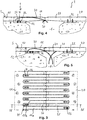
- a road joint according to a first embodiment is shown on the Figures 3 to 7 . It is intended to connect two parts of pavement C1, C2 separated by a slot F comprising two sets 1, 2 anchored respectively in one or other of the pavement portions on either side of the slot F, as in the prior art of the Figures 1 and 2 .
- Each set 1, 2 comprises a comb 10, 20 having a series of teeth 11, 21, the teeth 11, 21 of one of the combs 10, 20 being nested in the teeth 21, 11 of the other comb 20, 10 to ensure the continuity of the upper surface of the roadway when the road portions C1, C2 are struggling between a close position, as shown in FIG.
- each comb 10, 20 is fixed by screwing in inserts 120 embedded in concrete.
- Each set 1, 2 further comprises a sole 12, 22 extending along the slot F under the comb 10, 20 of said set.
- the sole 12, 22 extends between the implantation of the teeth 11, 21 of the comb 10, 20 and a line intermediate the implantation and the end of the teeth 11, 21.
- the seal comprises retractable means 3 adapted to fill, at least partially, the spaces between a first and a second tooth 11a, 11b adjacent the same comb 10 and a third tooth 21 of the other comb 20 inserted between the first and the second tooth 11a, 11b.
- the retractable means 3 relate to each comb 10, 20 and each space between the teeth 11, 21 of each comb 10, 20.
- the retractable means 3 comprise a flexible blade 30 extending between the first and second teeth 11a, 11b and passing under the third tooth 21 towards the slot F, and a base 31 extending under the flexible blade 30 and fixed on 12, 22.
- the flexible blade and the base 31 are in one piece, as shown by the Figures 6 and 7 , and connected to the opposite of the third tooth 21, that is to say at the implantation of the first and the third tooth 11a, 11b.
- the flexible blade is bent and forms an arch extending the entire length of the spaces between the teeth 11, 21 and extending into the slot F, so as to be flush with the upper surface S of the roadway in a spaced position.
- the base 31 is fixed on the sole 12, 22 by bolting two screws 32 in tapped holes of the sole 12, 22.
- the flexible blade 30 has a slot 33 facing the base 31 to access the heads of the screws 32 realizing bolting.
- the combs 10, 20 are made for example of stainless steel, likewise only soles and flexible blades. They could also be made of steel protected against corrosion by a coating.
- the slot F changes size struggling between the separated position as on the figure 4 and the close position, as shown on the figure 5 , and vice versa.
- the third tooth 21 slides on the upper face of the flexible blade 30 and pushes it downwards, inside the slot F.
- the blade 30 resumes its initial position under the effect of its elasticity. If a bicycle wheel passes over the flexible blade, it leans on it and descends only a few millimeters, without substantially penetrating between the first and second teeth 11a, 11b.
- the retractable means 3 comprises a telescopic tube 34 extending between the first and the second tooth facing the third tooth.
- the telescopic tube 34 is fixed on the sole 12, 22 by one of its ends 341, the other end 342 facing the third tooth 21, cantilevered.
- the telescopic tube 34 comprises a stand 343 which slides on the upper face of the sole 12, 22.
- the telescopic tube 34 comprises internal elastic means, not shown, which elastically hold the telescopic tube 34 in a deployed position .
- the tube seals the space between the first and second teeth permanently, without preventing the passage from the spaced apart position to the close position. If a bicycle wheel passes over the telescopic tube 34, it leans on it and descends only a few millimeters, without penetrating substantially between the first and the second tooth 11a, 11b.
- the retractable means 3 “comprise a base 31" extending under the flexible blade 30.
- the base 31 is a square section which can be continuous or the width of each blade 30". "is attached to the sole 12, while that the flexible blade 30 "is connected to the base 31" by hooks opposite the third tooth 21.
- the blade 30 “comprises a U-shaped fold 301, bearing on a first flange 311 of the base 31 which is along the flange 12.
- a second flange 312 of the base extends substantially at right angles to the first flange 311 and terminates in one of the hooks 313 of the connection with the flexible blade 30 ".
- Hook 313 having an open U shape facing the comb 10.
- One end of the blade 30 also includes a hook 302 which intermesh with the hook 313 of the base 31".
- the blade 30 In use, the blade 30 "is stretched in flexion by the support on the one hand at the hooks 313, 302, at the fold 301 and secondly under the third tooth 21.
- the blade 31" flexes during the transition from the closed position to the close position, as illustrated by the Figures 11 to 13 , the fold 301 remaining in support on the wing 311 of the base.
Landscapes
- Engineering & Computer Science (AREA)
- Architecture (AREA)
- Civil Engineering (AREA)
- Structural Engineering (AREA)
- Road Paving Structures (AREA)
Claims (6)
- Fahrbahnübergang zum Verbinden von zwei Fahrbahnteilen (C1, C2), die durch einen Spalt (F) getrennt sind, bestehend aus zwei Einheiten (1, 2), die jeweils in einem der beiden Fahrbahnteile (C1, C2) zu beiden Seiten des Spalts (F) verankert sind, wobei jede Einheit (1, 2) einen Kamm (10, 20) mit einer Reihe von Zähnen (11, 21) umfasst, und die Zähne (11, 21) des einen Kamms (10, 20) in die Zähne (21, 11) des anderen Kamms (20, 10) greifen, um die Kontinuität der Fahrbahnoberfläche (S) zu gewährleisten, wenn die Fahrbahnteile (C1, C2) sich zwischen einer angenäherten Lage, in welcher der Spalt (F) am schmalsten ist, und einer entfernten Lage bewegen, in welcher der Spalt (F) am breitesten ist, wobei der Übergang dadurch gekennzeichnet ist, dass er ausziehbare Mittel (3, 3') umfasst, die geeignet sind, die Räume zwischen einem ersten und einem benachbart angeordneten zweiten Zahn (11a, 11b) eines Kamms (10, 20) und einem dritten Zahn (21) des anderen Kamms (10, 20), der zwischen den ersten und den zweiten Zahn (11a, 11b) greift, zumindest teilweise zu überbrücken,
und die ausziehbaren Mittel (3, 3') eine biegsame Zunge (30) umfassen, die zwischen dem ersten und dem zweiten Zahn (11a, 11b) und unter dem dritten Zahn (21) zum Spalt (F) verläuft,
und jede Einheit (1, 2) zudem eine Sohlplatte (12, 22) umfasst, die entlang dem Spalt (F) unter dem Kamm (10, 20) der Einheit verläuft,
dadurch gekennzeichnet, dass die ausziehbaren Mittel (3, 3') ein Basisteil (31) umfassen, das unter der biegsamen Zunge (30) verläuft und an der Sohlplatte (12, 22) befestigt ist. - Fahrbahnübergang nach Anspruch 1, bei dem die biegsame Zunge (30) und das Basisteil (31) einstückig ausgebildet und gegenüberliegend dem dritten Zahn (21) verbunden sind.
- Fahrbahnübergang nach Anspruch 1 oder 2, bei dem das Basisteil (31) durch Schraubverbindung befestigt ist und die biegsame Zunge (30) ein Langloch für den Zugang zu Schrauben umfasst, mit denen die Verschraubung ausgeführt wird.
- Fahrbahnübergang nach Anspruch 1, bei dem die biegsame Zunge (30") mit Haken gegenüberliegend dem dritten Zahn (21) mit dem Basisteil (31") verbunden ist.
- Fahrbahnübergang nach Anspruch 4, bei dem die Zunge (30") eine U-förmige Falte (301) umfasst, die auf dem Basisteil (31") zur Auflage kommt.
- Fahrbahnübergang nach einem der vorhergehenden Ansprüche, bei dem die biegsame Zunge (30) so gewölbt ist, dass sie in entfernter Lage mit der Fahrbahnoberfläche (S) bündig ist.
Priority Applications (4)
| Application Number | Priority Date | Filing Date | Title |
|---|---|---|---|
| DK16182742.3T DK3279399T3 (da) | 2016-08-04 | 2016-08-04 | Kørebaneovergang til vejarbejder |
| SI201630343T SI3279399T1 (sl) | 2016-08-04 | 2016-08-04 | Cestni spoj za cestno strukturo |
| EP16182742.3A EP3279399B1 (de) | 2016-08-04 | 2016-08-04 | Fahrbahnübergang für strassenbauwerke |
| AU2017208357A AU2017208357A1 (en) | 2016-08-04 | 2017-07-28 | Roadway joint for road structure |
Applications Claiming Priority (1)
| Application Number | Priority Date | Filing Date | Title |
|---|---|---|---|
| EP16182742.3A EP3279399B1 (de) | 2016-08-04 | 2016-08-04 | Fahrbahnübergang für strassenbauwerke |
Publications (2)
| Publication Number | Publication Date |
|---|---|
| EP3279399A1 EP3279399A1 (de) | 2018-02-07 |
| EP3279399B1 true EP3279399B1 (de) | 2019-05-29 |
Family
ID=56609702
Family Applications (1)
| Application Number | Title | Priority Date | Filing Date |
|---|---|---|---|
| EP16182742.3A Active EP3279399B1 (de) | 2016-08-04 | 2016-08-04 | Fahrbahnübergang für strassenbauwerke |
Country Status (4)
| Country | Link |
|---|---|
| EP (1) | EP3279399B1 (de) |
| AU (1) | AU2017208357A1 (de) |
| DK (1) | DK3279399T3 (de) |
| SI (1) | SI3279399T1 (de) |
Families Citing this family (3)
| Publication number | Priority date | Publication date | Assignee | Title |
|---|---|---|---|---|
| KR101795337B1 (ko) * | 2017-01-25 | 2017-11-08 | 주식회사 케이이테크 | 걸침판부를 가지는 핑거 조인트 |
| CN110468700B (zh) * | 2019-09-17 | 2020-11-17 | 衡水中盛工程橡胶有限公司 | 一种桥梁用多功能伸缩缝装置 |
| CN113818307A (zh) * | 2021-09-17 | 2021-12-21 | 南昌大学 | 一种道路桥梁裂缝加固结构 |
Family Cites Families (6)
| Publication number | Priority date | Publication date | Assignee | Title |
|---|---|---|---|---|
| FR2573456B1 (fr) | 1984-11-20 | 1987-01-30 | Freyssinet Int Stup | Joints de chaussee |
| AT413829B (de) * | 1999-03-02 | 2006-06-15 | Reisner & Wolff Eng | Vorrichtung zum überbrücken von dehnfugen in fahrbahnen |
| FR2902118B1 (fr) | 2006-06-13 | 2008-08-15 | Equip Tech Pour L'ind De La Co | Joint de dilatation pour ouvrage routier |
| CN101956366B (zh) * | 2009-12-29 | 2016-09-28 | 吴树超 | 互支式桥梁伸缩装置 |
| DE112011104796T5 (de) * | 2011-01-31 | 2014-03-06 | Sergey Waleriewich Kozlachkov | Dehnungsfugen |
| CN102966036B (zh) * | 2012-11-18 | 2015-10-21 | 吴树超 | 链式无缝桥梁伸缩装置 |
-
2016
- 2016-08-04 SI SI201630343T patent/SI3279399T1/sl unknown
- 2016-08-04 DK DK16182742.3T patent/DK3279399T3/da active
- 2016-08-04 EP EP16182742.3A patent/EP3279399B1/de active Active
-
2017
- 2017-07-28 AU AU2017208357A patent/AU2017208357A1/en not_active Abandoned
Non-Patent Citations (1)
| Title |
|---|
| None * |
Also Published As
| Publication number | Publication date |
|---|---|
| SI3279399T1 (sl) | 2020-03-31 |
| AU2017208357A1 (en) | 2018-02-22 |
| EP3279399A1 (de) | 2018-02-07 |
| DK3279399T3 (da) | 2019-09-09 |
Similar Documents
| Publication | Publication Date | Title |
|---|---|---|
| EP2943693B1 (de) | Klemme zur befestigung einer platte an einem halter und auf diese weise hergestellte anordnung | |
| CA2220980C (fr) | Glissiere pour siege de vehicule, et siege equipe d'une telle glissiere | |
| WO2018114913A1 (fr) | Guidage de vitrage coulissant, en particulier automobile | |
| EP3279399B1 (de) | Fahrbahnübergang für strassenbauwerke | |
| EP0471596A2 (de) | Dichtungsvorrichtung mit aufblasbarer Dichtung für Türen oder mobile Panele | |
| FR2739066A1 (fr) | Glissiere verrouillable en position pour sieges de vehicules automobiles | |
| EP3144199B1 (de) | Vorrichtung zur erhöhung von komfort, insbesondere für ein schienenfahrzeug, umfassend einen herausnehmbaren tisch | |
| FR2814766A1 (fr) | Barriere de securite pour voies de circulation de vehicules munie d'au moins un ecran de protection | |
| EP2335527B1 (de) | Bettrahmen mit nach oben klappbarem Schlafelement | |
| EP3492675B1 (de) | Vorrichtung zum befestigen von lamellen an einem starren gitterpaneel, lamellenbefestigungskit an einem starren gitterpaneel und sichtschutzzaun, der mit diesem kit ausgestattet ist | |
| EP3095684B1 (de) | Lasche einer kettenschaltung | |
| CA2000622C (fr) | Support de siege pour vehicule de transport en commun et siege equipe de ce support | |
| EP2619394B1 (de) | Schwelle und und türflügelanordnung | |
| EP2222199A2 (de) | Schuh | |
| FR2783854A1 (fr) | Barre de seuil a rattrapage de niveau | |
| FR2896746A1 (fr) | Dispositif de connexion destine a relier un balai d'essuie- glace a un bras d'essuie-glace | |
| EP2746476A1 (de) | Schlitzabdeckvorrichtung für hydraulische Rinne | |
| FR3034801A1 (fr) | Profile de liaison pour un element de toiture, notamment pour abri telescopique de piscine | |
| FR2836495A1 (fr) | Dispositif de fixation de panneaux sur des glissieres de securite pour route ou autoroute | |
| EP2509851A1 (de) | Flexible aerodynamische vorrichtung | |
| CH680046A5 (de) | ||
| FR2645505A2 (fr) | Sachet pour produits liquides avec armature | |
| FR3071785B1 (fr) | Structure de siege de vehicule automobile dotee d’une agrafe de maintien d’un carter de recouvrement. | |
| FR2865984A1 (fr) | Plancher pour soufflet d'interconnexion entre deux voitures | |
| FR2569224A1 (fr) | Systeme de liaison par serrage pour arceaux de soutenement de galeries souterraines |
Legal Events
| Date | Code | Title | Description |
|---|---|---|---|
| PUAI | Public reference made under article 153(3) epc to a published international application that has entered the european phase |
Free format text: ORIGINAL CODE: 0009012 |
|
| STAA | Information on the status of an ep patent application or granted ep patent |
Free format text: STATUS: THE APPLICATION HAS BEEN PUBLISHED |
|
| AK | Designated contracting states |
Kind code of ref document: A1 Designated state(s): AL AT BE BG CH CY CZ DE DK EE ES FI FR GB GR HR HU IE IS IT LI LT LU LV MC MK MT NL NO PL PT RO RS SE SI SK SM TR |
|
| AX | Request for extension of the european patent |
Extension state: BA ME |
|
| STAA | Information on the status of an ep patent application or granted ep patent |
Free format text: STATUS: REQUEST FOR EXAMINATION WAS MADE |
|
| 17P | Request for examination filed |
Effective date: 20180802 |
|
| RBV | Designated contracting states (corrected) |
Designated state(s): AL AT BE BG CH CY CZ DE DK EE ES FI FR GB GR HR HU IE IS IT LI LT LU LV MC MK MT NL NO PL PT RO RS SE SI SK SM TR |
|
| GRAP | Despatch of communication of intention to grant a patent |
Free format text: ORIGINAL CODE: EPIDOSNIGR1 |
|
| STAA | Information on the status of an ep patent application or granted ep patent |
Free format text: STATUS: GRANT OF PATENT IS INTENDED |
|
| INTG | Intention to grant announced |
Effective date: 20181218 |
|
| GRAS | Grant fee paid |
Free format text: ORIGINAL CODE: EPIDOSNIGR3 |
|
| GRAA | (expected) grant |
Free format text: ORIGINAL CODE: 0009210 |
|
| STAA | Information on the status of an ep patent application or granted ep patent |
Free format text: STATUS: THE PATENT HAS BEEN GRANTED |
|
| AK | Designated contracting states |
Kind code of ref document: B1 Designated state(s): AL AT BE BG CH CY CZ DE DK EE ES FI FR GB GR HR HU IE IS IT LI LT LU LV MC MK MT NL NO PL PT RO RS SE SI SK SM TR |
|
| REG | Reference to a national code |
Ref country code: GB Ref legal event code: FG4D Free format text: NOT ENGLISH |
|
| REG | Reference to a national code |
Ref country code: CH Ref legal event code: EP |
|
| REG | Reference to a national code |
Ref country code: AT Ref legal event code: REF Ref document number: 1138336 Country of ref document: AT Kind code of ref document: T Effective date: 20190615 |
|
| REG | Reference to a national code |
Ref country code: DE Ref legal event code: R096 Ref document number: 602016014516 Country of ref document: DE |
|
| REG | Reference to a national code |
Ref country code: IE Ref legal event code: FG4D Free format text: LANGUAGE OF EP DOCUMENT: FRENCH |
|
| REG | Reference to a national code |
Ref country code: DK Ref legal event code: T3 Effective date: 20190904 |
|
| REG | Reference to a national code |
Ref country code: SE Ref legal event code: TRGR |
|
| REG | Reference to a national code |
Ref country code: NL Ref legal event code: MP Effective date: 20190529 |
|
| REG | Reference to a national code |
Ref country code: LT Ref legal event code: MG4D |
|
| REG | Reference to a national code |
Ref country code: NO Ref legal event code: T2 Effective date: 20190529 |
|
| PG25 | Lapsed in a contracting state [announced via postgrant information from national office to epo] |
Ref country code: HR Free format text: LAPSE BECAUSE OF FAILURE TO SUBMIT A TRANSLATION OF THE DESCRIPTION OR TO PAY THE FEE WITHIN THE PRESCRIBED TIME-LIMIT Effective date: 20190529 Ref country code: LT Free format text: LAPSE BECAUSE OF FAILURE TO SUBMIT A TRANSLATION OF THE DESCRIPTION OR TO PAY THE FEE WITHIN THE PRESCRIBED TIME-LIMIT Effective date: 20190529 Ref country code: AL Free format text: LAPSE BECAUSE OF FAILURE TO SUBMIT A TRANSLATION OF THE DESCRIPTION OR TO PAY THE FEE WITHIN THE PRESCRIBED TIME-LIMIT Effective date: 20190529 Ref country code: ES Free format text: LAPSE BECAUSE OF FAILURE TO SUBMIT A TRANSLATION OF THE DESCRIPTION OR TO PAY THE FEE WITHIN THE PRESCRIBED TIME-LIMIT Effective date: 20190529 Ref country code: PT Free format text: LAPSE BECAUSE OF FAILURE TO SUBMIT A TRANSLATION OF THE DESCRIPTION OR TO PAY THE FEE WITHIN THE PRESCRIBED TIME-LIMIT Effective date: 20190930 |
|
| PGFP | Annual fee paid to national office [announced via postgrant information from national office to epo] |
Ref country code: FI Payment date: 20190902 Year of fee payment: 4 Ref country code: DK Payment date: 20190902 Year of fee payment: 4 Ref country code: SE Payment date: 20190814 Year of fee payment: 4 |
|
| PG25 | Lapsed in a contracting state [announced via postgrant information from national office to epo] |
Ref country code: BG Free format text: LAPSE BECAUSE OF FAILURE TO SUBMIT A TRANSLATION OF THE DESCRIPTION OR TO PAY THE FEE WITHIN THE PRESCRIBED TIME-LIMIT Effective date: 20190829 Ref country code: RS Free format text: LAPSE BECAUSE OF FAILURE TO SUBMIT A TRANSLATION OF THE DESCRIPTION OR TO PAY THE FEE WITHIN THE PRESCRIBED TIME-LIMIT Effective date: 20190529 Ref country code: GR Free format text: LAPSE BECAUSE OF FAILURE TO SUBMIT A TRANSLATION OF THE DESCRIPTION OR TO PAY THE FEE WITHIN THE PRESCRIBED TIME-LIMIT Effective date: 20190830 Ref country code: LV Free format text: LAPSE BECAUSE OF FAILURE TO SUBMIT A TRANSLATION OF THE DESCRIPTION OR TO PAY THE FEE WITHIN THE PRESCRIBED TIME-LIMIT Effective date: 20190529 |
|
| RAP2 | Party data changed (patent owner data changed or rights of a patent transferred) |
Owner name: EQUIPEMENTS TECHNIQUES POUR L'INDUSTRIE DE LA CONS |
|
| REG | Reference to a national code |
Ref country code: AT Ref legal event code: MK05 Ref document number: 1138336 Country of ref document: AT Kind code of ref document: T Effective date: 20190529 |
|
| PG25 | Lapsed in a contracting state [announced via postgrant information from national office to epo] |
Ref country code: EE Free format text: LAPSE BECAUSE OF FAILURE TO SUBMIT A TRANSLATION OF THE DESCRIPTION OR TO PAY THE FEE WITHIN THE PRESCRIBED TIME-LIMIT Effective date: 20190529 Ref country code: NL Free format text: LAPSE BECAUSE OF FAILURE TO SUBMIT A TRANSLATION OF THE DESCRIPTION OR TO PAY THE FEE WITHIN THE PRESCRIBED TIME-LIMIT Effective date: 20190529 Ref country code: SK Free format text: LAPSE BECAUSE OF FAILURE TO SUBMIT A TRANSLATION OF THE DESCRIPTION OR TO PAY THE FEE WITHIN THE PRESCRIBED TIME-LIMIT Effective date: 20190529 Ref country code: AT Free format text: LAPSE BECAUSE OF FAILURE TO SUBMIT A TRANSLATION OF THE DESCRIPTION OR TO PAY THE FEE WITHIN THE PRESCRIBED TIME-LIMIT Effective date: 20190529 Ref country code: CZ Free format text: LAPSE BECAUSE OF FAILURE TO SUBMIT A TRANSLATION OF THE DESCRIPTION OR TO PAY THE FEE WITHIN THE PRESCRIBED TIME-LIMIT Effective date: 20190529 Ref country code: RO Free format text: LAPSE BECAUSE OF FAILURE TO SUBMIT A TRANSLATION OF THE DESCRIPTION OR TO PAY THE FEE WITHIN THE PRESCRIBED TIME-LIMIT Effective date: 20190529 |
|
| PG25 | Lapsed in a contracting state [announced via postgrant information from national office to epo] |
Ref country code: SM Free format text: LAPSE BECAUSE OF FAILURE TO SUBMIT A TRANSLATION OF THE DESCRIPTION OR TO PAY THE FEE WITHIN THE PRESCRIBED TIME-LIMIT Effective date: 20190529 Ref country code: IT Free format text: LAPSE BECAUSE OF FAILURE TO SUBMIT A TRANSLATION OF THE DESCRIPTION OR TO PAY THE FEE WITHIN THE PRESCRIBED TIME-LIMIT Effective date: 20190529 |
|
| REG | Reference to a national code |
Ref country code: DE Ref legal event code: R097 Ref document number: 602016014516 Country of ref document: DE Ref country code: DE Ref legal event code: R119 Ref document number: 602016014516 Country of ref document: DE |
|
| PG25 | Lapsed in a contracting state [announced via postgrant information from national office to epo] |
Ref country code: TR Free format text: LAPSE BECAUSE OF FAILURE TO SUBMIT A TRANSLATION OF THE DESCRIPTION OR TO PAY THE FEE WITHIN THE PRESCRIBED TIME-LIMIT Effective date: 20190529 |
|
| PLBE | No opposition filed within time limit |
Free format text: ORIGINAL CODE: 0009261 |
|
| STAA | Information on the status of an ep patent application or granted ep patent |
Free format text: STATUS: NO OPPOSITION FILED WITHIN TIME LIMIT |
|
| PG25 | Lapsed in a contracting state [announced via postgrant information from national office to epo] |
Ref country code: PL Free format text: LAPSE BECAUSE OF FAILURE TO SUBMIT A TRANSLATION OF THE DESCRIPTION OR TO PAY THE FEE WITHIN THE PRESCRIBED TIME-LIMIT Effective date: 20190529 |
|
| 26N | No opposition filed |
Effective date: 20200303 |
|
| PG25 | Lapsed in a contracting state [announced via postgrant information from national office to epo] |
Ref country code: LI Free format text: LAPSE BECAUSE OF NON-PAYMENT OF DUE FEES Effective date: 20190831 Ref country code: CH Free format text: LAPSE BECAUSE OF NON-PAYMENT OF DUE FEES Effective date: 20190831 Ref country code: MC Free format text: LAPSE BECAUSE OF FAILURE TO SUBMIT A TRANSLATION OF THE DESCRIPTION OR TO PAY THE FEE WITHIN THE PRESCRIBED TIME-LIMIT Effective date: 20190529 Ref country code: LU Free format text: LAPSE BECAUSE OF NON-PAYMENT OF DUE FEES Effective date: 20190804 |
|
| PG25 | Lapsed in a contracting state [announced via postgrant information from national office to epo] |
Ref country code: DE Free format text: LAPSE BECAUSE OF NON-PAYMENT OF DUE FEES Effective date: 20200303 Ref country code: IE Free format text: LAPSE BECAUSE OF NON-PAYMENT OF DUE FEES Effective date: 20190804 |
|
| PGFP | Annual fee paid to national office [announced via postgrant information from national office to epo] |
Ref country code: SI Payment date: 20200803 Year of fee payment: 5 |
|
| REG | Reference to a national code |
Ref country code: FI Ref legal event code: MAE |
|
| REG | Reference to a national code |
Ref country code: DK Ref legal event code: EBP Effective date: 20200831 |
|
| REG | Reference to a national code |
Ref country code: SE Ref legal event code: EUG |
|
| PG25 | Lapsed in a contracting state [announced via postgrant information from national office to epo] |
Ref country code: FI Free format text: LAPSE BECAUSE OF NON-PAYMENT OF DUE FEES Effective date: 20200804 |
|
| PG25 | Lapsed in a contracting state [announced via postgrant information from national office to epo] |
Ref country code: SE Free format text: LAPSE BECAUSE OF NON-PAYMENT OF DUE FEES Effective date: 20200805 Ref country code: CY Free format text: LAPSE BECAUSE OF FAILURE TO SUBMIT A TRANSLATION OF THE DESCRIPTION OR TO PAY THE FEE WITHIN THE PRESCRIBED TIME-LIMIT Effective date: 20190529 |
|
| PG25 | Lapsed in a contracting state [announced via postgrant information from national office to epo] |
Ref country code: IS Free format text: LAPSE BECAUSE OF FAILURE TO SUBMIT A TRANSLATION OF THE DESCRIPTION OR TO PAY THE FEE WITHIN THE PRESCRIBED TIME-LIMIT Effective date: 20190929 |
|
| PG25 | Lapsed in a contracting state [announced via postgrant information from national office to epo] |
Ref country code: MT Free format text: LAPSE BECAUSE OF FAILURE TO SUBMIT A TRANSLATION OF THE DESCRIPTION OR TO PAY THE FEE WITHIN THE PRESCRIBED TIME-LIMIT Effective date: 20190529 Ref country code: HU Free format text: LAPSE BECAUSE OF FAILURE TO SUBMIT A TRANSLATION OF THE DESCRIPTION OR TO PAY THE FEE WITHIN THE PRESCRIBED TIME-LIMIT; INVALID AB INITIO Effective date: 20160804 |
|
| PG25 | Lapsed in a contracting state [announced via postgrant information from national office to epo] |
Ref country code: DK Free format text: LAPSE BECAUSE OF NON-PAYMENT OF DUE FEES Effective date: 20200831 |
|
| REG | Reference to a national code |
Ref country code: SI Ref legal event code: KO00 Effective date: 20220407 |
|
| PG25 | Lapsed in a contracting state [announced via postgrant information from national office to epo] |
Ref country code: MK Free format text: LAPSE BECAUSE OF FAILURE TO SUBMIT A TRANSLATION OF THE DESCRIPTION OR TO PAY THE FEE WITHIN THE PRESCRIBED TIME-LIMIT Effective date: 20190529 |
|
| PGFP | Annual fee paid to national office [announced via postgrant information from national office to epo] |
Ref country code: GB Payment date: 20220831 Year of fee payment: 7 |
|
| PGFP | Annual fee paid to national office [announced via postgrant information from national office to epo] |
Ref country code: BE Payment date: 20220831 Year of fee payment: 7 |
|
| GBPC | Gb: european patent ceased through non-payment of renewal fee |
Effective date: 20230804 |
|
| REG | Reference to a national code |
Ref country code: BE Ref legal event code: MM Effective date: 20230831 |
|
| PG25 | Lapsed in a contracting state [announced via postgrant information from national office to epo] |
Ref country code: GB Free format text: LAPSE BECAUSE OF NON-PAYMENT OF DUE FEES Effective date: 20230804 |
|
| PG25 | Lapsed in a contracting state [announced via postgrant information from national office to epo] |
Ref country code: GB Free format text: LAPSE BECAUSE OF NON-PAYMENT OF DUE FEES Effective date: 20230804 |
|
| PG25 | Lapsed in a contracting state [announced via postgrant information from national office to epo] |
Ref country code: BE Free format text: LAPSE BECAUSE OF NON-PAYMENT OF DUE FEES Effective date: 20230831 |
|
| PGFP | Annual fee paid to national office [announced via postgrant information from national office to epo] |
Ref country code: NO Payment date: 20250826 Year of fee payment: 10 |
|
| PGFP | Annual fee paid to national office [announced via postgrant information from national office to epo] |
Ref country code: FR Payment date: 20250825 Year of fee payment: 10 |