EP3277137B1 - Beverage preparation device - Google Patents
Beverage preparation device Download PDFInfo
- Publication number
- EP3277137B1 EP3277137B1 EP16718511.5A EP16718511A EP3277137B1 EP 3277137 B1 EP3277137 B1 EP 3277137B1 EP 16718511 A EP16718511 A EP 16718511A EP 3277137 B1 EP3277137 B1 EP 3277137B1
- Authority
- EP
- European Patent Office
- Prior art keywords
- compression
- brewing
- compression element
- tubular wall
- curved trajectory
- Prior art date
- Legal status (The legal status is an assumption and is not a legal conclusion. Google has not performed a legal analysis and makes no representation as to the accuracy of the status listed.)
- Active
Links
Images


Classifications
-
- A—HUMAN NECESSITIES
- A47—FURNITURE; DOMESTIC ARTICLES OR APPLIANCES; COFFEE MILLS; SPICE MILLS; SUCTION CLEANERS IN GENERAL
- A47J—KITCHEN EQUIPMENT; COFFEE MILLS; SPICE MILLS; APPARATUS FOR MAKING BEVERAGES
- A47J31/00—Apparatus for making beverages
- A47J31/24—Coffee-making apparatus in which hot water is passed through the filter under pressure, i.e. in which the coffee grounds are extracted under pressure
- A47J31/34—Coffee-making apparatus in which hot water is passed through the filter under pressure, i.e. in which the coffee grounds are extracted under pressure with hot water under liquid pressure
- A47J31/36—Coffee-making apparatus in which hot water is passed through the filter under pressure, i.e. in which the coffee grounds are extracted under pressure with hot water under liquid pressure with mechanical pressure-producing means
- A47J31/3604—Coffee-making apparatus in which hot water is passed through the filter under pressure, i.e. in which the coffee grounds are extracted under pressure with hot water under liquid pressure with mechanical pressure-producing means with a mechanism arranged to move the brewing chamber between loading, infusing and ejecting stations
- A47J31/3609—Loose coffee being employed
- A47J31/3614—Means to perform transfer from a loading position to an infusing position
-
- A—HUMAN NECESSITIES
- A47—FURNITURE; DOMESTIC ARTICLES OR APPLIANCES; COFFEE MILLS; SPICE MILLS; SUCTION CLEANERS IN GENERAL
- A47J—KITCHEN EQUIPMENT; COFFEE MILLS; SPICE MILLS; APPARATUS FOR MAKING BEVERAGES
- A47J31/00—Apparatus for making beverages
- A47J31/005—Portable or compact beverage making apparatus, e.g. for travelling, for use in automotive vehicles
-
- A—HUMAN NECESSITIES
- A47—FURNITURE; DOMESTIC ARTICLES OR APPLIANCES; COFFEE MILLS; SPICE MILLS; SUCTION CLEANERS IN GENERAL
- A47J—KITCHEN EQUIPMENT; COFFEE MILLS; SPICE MILLS; APPARATUS FOR MAKING BEVERAGES
- A47J31/00—Apparatus for making beverages
- A47J31/44—Parts or details or accessories of beverage-making apparatus
- A47J31/46—Dispensing spouts, pumps, drain valves or like liquid transporting devices
Definitions
- the invention relates to a beverage preparation device, such as used for preparing coffee, in particular espresso.
- Beverage preparation devices using a horizontally arranged brewing chamber and corresponding horizontally or vertically arranged pistons are known in practice.
- the document EP 0 937 432 A1 discloses a coffee machine with horizontally arranged brewing chamber and piston.
- a problem with so arranged beverage preparation devices is that they take up a lot of space.
- An object of the present invention is thus to provide a beverage preparation device, which takes up less space.
- a beverage preparation device comprising;
- the curved trajectory concerns a circle being concentric with respect to the central axis.
- the device after entering the idle position, the device will usually immediately proceed to the filling position to commence a further cycle. Therefore, the device may be idle in the idle position for only a very short period.
- Another embodiment relates to an aforementioned device, wherein the central axis extends in a horizontal direction, i.e. the device has an orientation similar to a giant wheel.
- use can be made of gravity. For example, when the beverage is prepared in the brewing space, gravity can be used to discharge the beverage from the brewing chamber.
- Another embodiment relates to an aforementioned device, wherein the central axis extends in a vertical direction, as opposed to a horizontal direction.
- the central axis may be beneficial, for instance when the brewing chamber is relatively large and heavy and moving the brewing chamber around the axis would require a lot of energy.
- Another embodiment relates to an aforementioned device, wherein the opening is formed by an open longitudinal end, when seen along the curved trajectory, of the tubular wall.
- Such an opening will be relatively large and can be advantageously used to receive the ingredient powder, without spilling the powder.
- Another embodiment relates to an aforementioned device, wherein the first compression element is static.
- the moving parts will then be formed by the second compression element and the brewing chamber. Due to the first compression element being static, energy will be saved and the device's mechanical reliability will increase.
- Another embodiment relates to an aforementioned device, wherein the second compression element can be dragged along by an outer longitudinal end of the tubular wall of the brewing chamber.
- This closed longitudinal end will normally be the longitudinal end opposing the (open) longitudinal end comprising the opening for receiving the powder.
- Another embodiment relates to an aforementioned device, wherein the second compression element is provided with a reversible locking mechanism, wherein the reversible locking mechanism is arranged for locking the second compression element in a locked state, preventing movement thereof along the curved trajectory, and unlocking the second compression element in an unlocked state, for allowing the second compression element to be dragged along by the brewing chamber along the curved trajectory.
- the reversible locking mechanism may be formed by a spring-biased locking mechanism or by a magnetic locking mechanism, wherein a magnet is arranged at the non-compression end of the second compression element and a corresponding piece of metal is arranged on a stationary part of the device (or vice versa).
- Another embodiment relates to an aforementioned device, wherein, when the opening is formed by an open longitudinal end of the tubular wall, in the filling position, the opening of the open longitudinal end extends in a horizontal direction.
- the ingredient powder can be conveniently deposited in the filling space by using gravity.
- Another embodiment relates to an aforementioned device, wherein, in the brewing position, the water inlet is arranged for injecting water in a circumferential space between the tubular wall and the outer circumference of the first compression element, wherein the circumferential space is in fluid connection with the brewing space.
- Another embodiment relates to an aforementioned device, wherein a compression plane comprising a compression surface of the first and/or second compression element extends at such a perpendicular distance from the central axis, that the compression surface of the first compression element and the compression surface of the second compression element are parallel in the brewing position, such that an even compression of the powder is obtained.
- Another embodiment relates to an aforementioned device, wherein the compression surfaces of the first and second compression elements are elliptical or oval, wherein the ellipse or oval comprises a long axis and a short axis, wherein the long axis runs parallel to the central axis.
- Such shapes prevent or at least counteract the occurrence of uneven compression of the ingredient powder.
- Another embodiment relates to an aforementioned device, wherein the brewing chamber is connected to a drive mechanism to drive the brewing chamber along the curved trajectory.
- Another embodiment relates to an aforementioned device, wherein a rotatable shaft is arranged at the position of the central axis, wherein the shaft is part of the drive mechanism, wherein the shaft is driven by a drive motor to drive the brewing chamber along the curved trajectory.
- Another embodiment relates to an aforementioned device, wherein an outer circumference of the tubular wall of the brewing chamber is provided with a rack-and-pinion drive mechanism arranged to drive the tubular wall along the curved trajectory.
- the rack is then provided along the outer circumference of the tubular wall, whereas the pinion is connected to a drive motor.
- Another embodiment relates to an aforementioned device, wherein the beverage outlet is arranged in the second compression element to obtain an even more compact design of the device.
- Another embodiment relates to an aforementioned device, wherein the beverage outlet is provided with a pressure valve.
- the pressure valve allows the beverage to be obtained at the right pressure.
- the powder can be unevenly compressed in some cases, causing uneven distribution of the hot water though the compressed powder. This is prevented by the pressure valve, which opens only when a predetermined pressure value is exceeded.
- Another embodiment relates to an aforementioned device, wherein, when the opening is formed by an open longitudinal end of the tubular wall, in the idle position the opening of the open longitudinal end extends in a vertical direction, wherein the compression surface of the second compression element is aligned with the opening.
- a beverage preparation device 1 such as for preparing espresso, is shown, comprising a central axis 2 with a brewing plane perpendicular to the central axis 2.
- the brewing plane comprises a curved trajectory 3, curved with respect to the central axis 2.
- the curved trajectory 3 preferably is concentric with respect to the central axis 2.
- the central axis 2 may extend in a horizontal direction, as shown, or a vertical direction.
- the device 1 is arranged on a mounting plate 30, which can be part of, or connected to, a beverage dispensing machine.
- Figure 2 shows a first 4 and second 5 compression element, arranged for movement relative to each other along the curved trajectory 3.
- the compression elements 4, 5 generally extend perpendicular to the curved trajectory 3.
- a brewing chamber 6 is furthermore provided, arranged for movement relative to the first 4 and second 5 compression elements along the curved trajectory 3.
- the brewing chamber 6 has a tubular wall 7, in particular a cylindrical wall, extending parallel to (along) the curved trajectory 3.
- the tubular wall 7 is arranged to be moved over an outer circumference 8, 9 of the first 4 and/or second 5 compression elements.
- the first compression element 4 is fixed/stationary. Both compression elements 4, 5 may be formed as pistons. This holds in particular for the second compression element 5.
- the compression elements 4, 5 may have an outer diameter of for instance 5-10 cm, preferably around 5 cm.
- the compression surface of the compression elements 4, 5 is circular, although other shapes are also conceivable.
- the device 1 as a whole may have an outer diameter (in the brewing plane) of 10-20 cm, such as about 20 cm, although for preparing larger quantities of beverage larger dimensions are also conceivable.
- the device may have a 'depth' of for instance, 5-10 cm, such as around 7 cm.
- Figure 2 shows the device 1 in an idle position I.
- the first 4 and second compression elements 5 are then spaced-apart along the curved trajectory 3.
- the idle position I can also be viewed as the end position, i.e. the position wherein the brewing process is completed and the spent powder pill is ejected.
- Figure 3 shows the device 1 in a filling position II.
- the tubular wall 7 is moved relative to the first compression element 4 along the curved trajectory 3, such that a filling space 10 is formed delimited by the tubular wall 7 and the second compression element 5.
- the tubular wall 7 comprises an opening 11 for receiving a powder 12 for preparing the beverage in the filling space 10.
- the opening 11 extends horizontally to facilitate filling of the filling space 10 with powder 12.
- the opening 11 is formed by an open longitudinal end 16, when seen along the curved trajectory 3, of the tubular wall 7.
- Figure 4 shows the device 1 in a brewing position III.
- the first 4 and second 5 compression elements are moved towards each other along the curved trajectory 3 to compress the powder 12.
- the tubular wall 7 is moved over the first 4 and second 5 compression elements, such that the first 4 and second 5 compression elements and the tubular wall 7 enclose a brewing space 13 for preparing the beverage with the powder 12.
- the device 1 furthermore comprises a water inlet 14 arranged for discharging water into the brewing space 13 and a beverage outlet 15 arranged for discharging beverage from the brewing space 13.
- the second compression element 5 is dragged along by a closed longitudinal end 17 of the tubular wall 7 of the brewing chamber 6 when the device 1 transits from the filling position II ( figure 3 ) to the brewing position III ( figure 4 ).
- the closed longitudinal end 17 is thereto provided with appropriate edges to pull the second compression element 5 along towards the first compression element 4.
- friction caused by the sealing ring 28 between the second compression element 5 and the brewing chamber 6, i.e. the tubular wall 7) will cause the second compression element 5 to be moved towards its idle position I by the brewing chamber 6.
- the second compression element 2 (i.e. the end thereof not needed for compression of the powder) is provided with a spring-biased locking mechanism 18 comprising a clamp (which more or less has properties similar to a leaf spring) with engages a protruding part of the device 1 in the idle position I and the filling position II.
- the locking mechanism 18 is arranged for locking the second compression element 5 in a locked state, preventing movement thereof along the curved trajectory 3, and unlocking the second compression element 5 in an unlocked state, for allowing the second compression element 5 to be dragged along by the brewing chamber 6 along the curved trajectory 3.
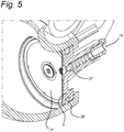
- the water inlet 14 is arranged for injecting water in a circumferential space 19 between the tubular wall 7 and the outer circumference 8 of the first compression element 5.
- the tight circumferential space 19 is in fluid connection with the brewing space 13 to allow the injected water to reach the brewing space 13. Due to the injected, hot water first reaching the outer regions of the compressed powder 12 an even distribution of the water throughout the compressed powder 12 is achieved.
- a sealing ring 29 is provided for preventing the injected water from leaking out at the wrong side of the circumferential space 19, i.e. for making sure that the water is forced towards the brewing space 13 only.
- a compression plane 32 comprising a compression surface 20 of the first 4 (and/or second compression element 5) extends at such a perpendicular distance 22 from the central axis 2, that the compression surface 20 of the first compression element 4 and the compression surface 21 of the second compression 5 element are parallel in the brewing position III, such that an even compression of the powder 12 is obtained.
- the compression surfaces 20, 21 of the first 4 and second compression elements 5 can be elliptical (not shown), wherein the ellipse comprises a long axis and a short axis, wherein the long axis runs parallel to the central axis 2.
- the brewing chamber 6 is connected to a drive mechanism 23 to drive the brewing chamber 6 along the curved trajectory.
- a rotatable shaft 24 can be arranged at the position of the central axis 2, wherein the shaft is part of the drive mechanism 23, wherein the shaft 24 is driven by a drive motor (not shown) to drive the brewing chamber 6 along the curved trajectory 3.
- the non-compression end of the second compression element 5 (the end that 'protrudes' through a corresponding hole in the generally closed end 17 of the tubular wall 7) may be connected to a bracket, plate or similar connection means, that in turn is arranged for rotating (freely) around the shaft 24.
- an outer circumference 25 of the tubular wall 7 of the brewing chamber 6 is provided with a rack-and-pinion drive mechanism 26 arranged to drive the tubular wall 7 along the curved trajectory 3 (as shown in figure 3 ).
- the beverage outlet 15 is arranged in the second compression element 5.
- a sieve 31 or the like can be provided.
- the beverage outlet 15 is provided with a pressure valve 27 that only opens when a predetermined water pressure in the brewing space 13 is exceeded.
- the beverage outlet 15 can be arranged away from the geometric center of the compression surface 21, i.e. more towards the central axis 2.
- the opening 11 of the open longitudinal end 16 preferably extends in a vertical direction and the compression surface 21 of the second compression element 5 is aligned with the opening 11 to eject a spent powder pill out of the opening 11.
Landscapes
- Engineering & Computer Science (AREA)
- Food Science & Technology (AREA)
- Mechanical Engineering (AREA)
- Apparatus For Making Beverages (AREA)
- Tea And Coffee (AREA)
- Beverage Vending Machines With Cups, And Gas Or Electricity Vending Machines (AREA)
Priority Applications (2)
| Application Number | Priority Date | Filing Date | Title |
|---|---|---|---|
| HRP20191509 HRP20191509T1 (hr) | 2015-03-31 | 2016-03-10 | Uređaj za pripremu napitka |
| PL16718511T PL3277137T3 (pl) | 2015-03-31 | 2016-03-10 | Urządzenie do przygotowywania napojów |
Applications Claiming Priority (2)
| Application Number | Priority Date | Filing Date | Title |
|---|---|---|---|
| NL2014557A NL2014557B1 (en) | 2015-03-31 | 2015-03-31 | Beverage preparation device. |
| PCT/NL2016/050173 WO2016159760A1 (en) | 2015-03-31 | 2016-03-10 | Beverage preparation device |
Publications (2)
| Publication Number | Publication Date |
|---|---|
| EP3277137A1 EP3277137A1 (en) | 2018-02-07 |
| EP3277137B1 true EP3277137B1 (en) | 2019-05-22 |
Family
ID=53277003
Family Applications (1)
| Application Number | Title | Priority Date | Filing Date |
|---|---|---|---|
| EP16718511.5A Active EP3277137B1 (en) | 2015-03-31 | 2016-03-10 | Beverage preparation device |
Country Status (16)
| Country | Link |
|---|---|
| US (1) | US10602870B2 (pl) |
| EP (1) | EP3277137B1 (pl) |
| KR (1) | KR102413350B1 (pl) |
| CN (1) | CN107529906B (pl) |
| AU (1) | AU2016241221B2 (pl) |
| CA (1) | CA2981229C (pl) |
| CY (1) | CY1122780T1 (pl) |
| DK (1) | DK3277137T3 (pl) |
| ES (1) | ES2742536T3 (pl) |
| HR (1) | HRP20191509T1 (pl) |
| HU (1) | HUE044994T2 (pl) |
| NL (1) | NL2014557B1 (pl) |
| PL (1) | PL3277137T3 (pl) |
| PT (1) | PT3277137T (pl) |
| RU (1) | RU2704892C2 (pl) |
| WO (1) | WO2016159760A1 (pl) |
Families Citing this family (6)
| Publication number | Priority date | Publication date | Assignee | Title |
|---|---|---|---|---|
| FR3072685B1 (fr) * | 2017-10-20 | 2020-11-06 | Total Marketing Services | Composition pour refroidir et lubrifier un systeme de motorisation d'un vehicule |
| CN111184441B (zh) * | 2020-03-02 | 2022-03-15 | 广东格兰仕集团有限公司 | 变轨组件及酿造装置 |
| WO2025155321A1 (en) | 2024-01-18 | 2025-07-24 | Sharkninja Operating Llc | Suggesting coffee bean grind size for beverage machines |
| WO2025155323A1 (en) | 2024-01-18 | 2025-07-24 | Sharkninja Operating Llc | Preventing coffee bean grinder jamming |
| US12369744B1 (en) | 2024-01-18 | 2025-07-29 | Sharkninja Operating Llc | Preparation of beverage machines for cold beverage brewing |
| EP4623766A1 (en) * | 2024-03-29 | 2025-10-01 | Zhejiang Xiwen Intelligent Technology Co., Ltd | Extraction mechanism of coffee maker |
Family Cites Families (52)
| Publication number | Priority date | Publication date | Assignee | Title |
|---|---|---|---|---|
| US1947523A (en) * | 1932-04-30 | 1934-02-20 | Millie Patent Holding Co Inc | Bag for coffee percolators |
| NZ337538A (en) * | 1997-03-13 | 2001-04-27 | Egro Ag | Automatic coffee maker comprising at least one cylindrical brewing chamber |
| CH692443A5 (de) * | 1998-01-26 | 2002-06-28 | Fianara Int Bv | Kaffeemaschine. |
| EP1000574A1 (fr) * | 1998-11-16 | 2000-05-17 | Societe Des Produits Nestle S.A. | Procédé et dispositif d'extraction d'une capsule fermée |
| SI1046366T1 (pl) * | 1999-04-23 | 2005-08-31 | Fianara Int Bv | |
| AU2003260870A1 (en) * | 2002-09-27 | 2004-04-19 | Koninklijke Philips Electronics N.V. | Apparatus for preparing coffee |
| CN101080358B (zh) * | 2004-10-19 | 2016-02-10 | 皇家戴维艾格伯茨有限公司 | 制备适于消费的饮料的系统和方法 |
| EP1767129B2 (en) * | 2005-09-27 | 2016-10-26 | Nestec S.A. | Extraction module for a capsule-based beverage production device |
| US7600466B2 (en) * | 2006-02-13 | 2009-10-13 | Eldom Rothrist Ag | Apparatus for filling and emptying a brewing chamber |
| US7513192B2 (en) * | 2006-03-23 | 2009-04-07 | Keurig, Incorporated | Beverage forming device with opening/closing mechanism for a beverage cartridge receiver |
| DK2033551T3 (da) * | 2006-05-24 | 2011-04-18 | Nestec Sa | Kapselperforeringsmodul |
| CA2661501A1 (en) * | 2006-08-25 | 2008-02-28 | Delica Ag | Means for penetrating a portion packaging containing an extraction product, device for extracting the extraction product contained in the portion packaging, and method for producing the means |
| EP2059156B1 (en) * | 2006-09-07 | 2010-04-21 | Keurig, Incorporated | Method and apparatus for beverage formation |
| GB2449421B (en) * | 2007-05-18 | 2009-09-09 | Kraft Foods R & D Inc | Improvements in or relating to beverage preparation machines |
| EP2155019B1 (en) * | 2007-06-05 | 2011-04-06 | Nestec S.A. | Method for preparing a beverage or liquid food |
| ITPN20070049A1 (it) * | 2007-07-09 | 2009-01-10 | N & W Global Vending Spa | "gruppo infusore" |
| ITMI20071441A1 (it) * | 2007-07-18 | 2009-01-19 | De Longhi Appliances Srl | Macchina da caffe' e procedimento per il suo controllo |
| DK2071986T3 (da) | 2007-12-18 | 2012-05-21 | Nestec Sa | System til fremstilling af en drikkevare ud af ingredienser og ved hjælp af en kodet indsats |
| CN101969823B (zh) * | 2008-03-14 | 2013-05-29 | 摩考菲股份公司 | 制备饮料用的装置和包囊 |
| CN102118991B (zh) * | 2008-08-01 | 2014-10-29 | 罗西有限公司 | 浓缩咖啡机冲泡组件 |
| EP2238878A1 (en) * | 2009-04-09 | 2010-10-13 | Nestec S.A. | Beverage preparation device having a closing mechanism with force demultiplying means |
| EP2241228B1 (en) * | 2009-04-17 | 2011-11-30 | N&W Global Vending S.p.A. | Brewing apparatus for automatic machines for producing brewed beverages |
| WO2012020343A1 (en) * | 2010-08-13 | 2012-02-16 | Koninklijke Philips Electronics N.V. | Brewing device for preparing a food product. |
| WO2012046195A1 (en) * | 2010-10-08 | 2012-04-12 | Koninklijke Philips Electronics N.V. | Brewing unit with horizontal motion |
| CN102008238B (zh) * | 2010-10-28 | 2013-04-17 | 汕头市自在天茶道科技有限公司 | 饮料冲泡装置 |
| US20150079240A1 (en) * | 2010-11-09 | 2015-03-19 | Gian Matteo Lo Foro | Capsule based system for preparing and dispensing a beverage |
| PL2637532T3 (pl) * | 2010-11-09 | 2016-07-29 | La Vit Tech Llc | Kapsułkowy układ sporządzania i wydawania napojów |
| US9155418B2 (en) * | 2010-11-15 | 2015-10-13 | Conair Corporation | Brewed beverage appliance and method |
| WO2012114218A1 (en) * | 2011-02-25 | 2012-08-30 | Koninklijke Philips Electronics N.V. | Brewing assembly and beverages production machine comprising said assembly |
| EP2543290A1 (en) * | 2011-07-08 | 2013-01-09 | Koninklijke Philips Electronics N.V. | Brewing unit with a water heater |
| US10080459B2 (en) * | 2011-11-09 | 2018-09-25 | La Vit Technology Llc | Capsule-based system for preparing and dispensing a beverage |
| US10034570B2 (en) * | 2011-11-09 | 2018-07-31 | LaVit Technology LLC | Capsule based system for preparing and dispensing a beverage |
| GB2499005B (en) * | 2012-02-02 | 2014-06-25 | Kraft Foods R & D Inc | Improvements in or relating to beverage preparation machines |
| AU2013217541B2 (en) * | 2012-02-09 | 2017-05-25 | Keurig Green Mountain, Inc. | Beverage forming device and method with cartridge retainer |
| AU2013217593B9 (en) * | 2012-02-09 | 2017-02-16 | Keurig Green Mountain, Inc. | Beverage forming device and method with moving beverage cartridge holder |
| JP6182544B2 (ja) * | 2012-02-09 | 2017-08-16 | キューリグ グリーン マウンテン インク | 複部構成の飲料カートリッジホルダを用いた飲料生成デバイスおよび飲料生成方法 |
| CN104254268B (zh) * | 2012-02-09 | 2018-03-20 | 库里格绿山股份有限公司 | 具有触动按钮的饮料形成装置和方法 |
| RU2637099C2 (ru) * | 2012-09-13 | 2017-11-29 | Конинклейке Филипс Н.В. | Узел для получения напитка и машина |
| US8960078B2 (en) * | 2013-03-14 | 2015-02-24 | Keurig Green Mountain, Inc. | Reusable beverage cartridge |
| CA2905217C (en) * | 2013-04-03 | 2016-11-08 | 2266170 Ontario Inc. | Capsule machine and components |
| TW201529023A (zh) * | 2013-07-10 | 2015-08-01 | Keurig Green Mountain Inc | 具有阻尼式移動的飲料機匣座 |
| ITTO20130589A1 (it) * | 2013-07-12 | 2015-01-13 | Lavazza Luigi Spa | Sistema per la preparazione di bevande |
| US9320382B2 (en) * | 2013-07-15 | 2016-04-26 | La Vit Technology Llc | Capsule based system for preparing and dispensing a beverage |
| ES2637216T3 (es) * | 2013-07-31 | 2017-10-11 | Rheavendors Services S.P.A. | Aparato para preparar bebidas |
| PL2832270T3 (pl) * | 2013-07-31 | 2016-08-31 | Rheavendors Services Spa | Sposób i urządzenie do przyrządzania i dozowania kawy |
| CN105636488A (zh) * | 2013-10-18 | 2016-06-01 | K-Fee系统股份有限公司 | 用于制备饮料的系统和方法 |
| EP3079531B1 (en) * | 2013-12-11 | 2019-02-06 | Nestec S.A. | Beverage machine with a pivotable capsule gate |
| US10136754B2 (en) * | 2014-01-17 | 2018-11-27 | Keurig Green Mountain, Inc. | Beverage machine cartridge holder |
| EP3142525B1 (en) * | 2014-05-12 | 2018-04-11 | Nestec S.A. | Beverage brewing unit particularly for machines for preparing beverages from capsules |
| WO2017108759A1 (en) * | 2015-12-22 | 2017-06-29 | Koninklijke Philips N.V. | Brewing unit for a beverage producing machine and machine containing the brewing unit |
| CN106993951B (zh) * | 2016-01-26 | 2019-07-19 | 漳州灿坤实业有限公司 | 酿造装置 |
| NL2017282B1 (en) * | 2016-08-03 | 2018-02-14 | Douwe Egberts Bv | System for preparing a beverage |
-
2015
- 2015-03-31 NL NL2014557A patent/NL2014557B1/en active
-
2016
- 2016-03-10 PT PT16718511T patent/PT3277137T/pt unknown
- 2016-03-10 EP EP16718511.5A patent/EP3277137B1/en active Active
- 2016-03-10 US US15/562,906 patent/US10602870B2/en active Active
- 2016-03-10 AU AU2016241221A patent/AU2016241221B2/en not_active Ceased
- 2016-03-10 CN CN201680023367.2A patent/CN107529906B/zh not_active Expired - Fee Related
- 2016-03-10 PL PL16718511T patent/PL3277137T3/pl unknown
- 2016-03-10 WO PCT/NL2016/050173 patent/WO2016159760A1/en not_active Ceased
- 2016-03-10 RU RU2017134498A patent/RU2704892C2/ru active
- 2016-03-10 ES ES16718511T patent/ES2742536T3/es active Active
- 2016-03-10 DK DK16718511.5T patent/DK3277137T3/da active
- 2016-03-10 CA CA2981229A patent/CA2981229C/en active Active
- 2016-03-10 HU HUE16718511 patent/HUE044994T2/hu unknown
- 2016-03-10 HR HRP20191509 patent/HRP20191509T1/hr unknown
- 2016-03-10 KR KR1020177031357A patent/KR102413350B1/ko active Active
-
2019
- 2019-08-14 CY CY20191100879T patent/CY1122780T1/el unknown
Non-Patent Citations (1)
| Title |
|---|
| None * |
Also Published As
| Publication number | Publication date |
|---|---|
| HUE044994T2 (hu) | 2019-11-28 |
| HRP20191509T1 (hr) | 2019-11-29 |
| ES2742536T3 (es) | 2020-02-14 |
| US10602870B2 (en) | 2020-03-31 |
| KR20180115211A (ko) | 2018-10-22 |
| DK3277137T3 (da) | 2019-08-19 |
| US20180078076A1 (en) | 2018-03-22 |
| NL2014557B1 (en) | 2017-01-06 |
| CA2981229C (en) | 2023-09-05 |
| CN107529906B (zh) | 2019-12-06 |
| AU2016241221B2 (en) | 2020-10-01 |
| CY1122780T1 (el) | 2021-05-05 |
| KR102413350B1 (ko) | 2022-06-27 |
| RU2017134498A (ru) | 2019-04-05 |
| RU2704892C2 (ru) | 2019-10-31 |
| NL2014557A (en) | 2016-10-10 |
| CA2981229A1 (en) | 2016-10-06 |
| RU2017134498A3 (pl) | 2019-08-29 |
| CN107529906A (zh) | 2018-01-02 |
| WO2016159760A1 (en) | 2016-10-06 |
| AU2016241221A1 (en) | 2017-10-26 |
| EP3277137A1 (en) | 2018-02-07 |
| PT3277137T (pt) | 2019-08-30 |
| PL3277137T3 (pl) | 2019-10-31 |
Similar Documents
| Publication | Publication Date | Title |
|---|---|---|
| CA2981229C (en) | Beverage preparation device | |
| EP2572610B1 (de) | Vorrichtung zur Zubereitung eines Getränkes und Kapsel dazu | |
| CN101772315B (zh) | 咖啡机 | |
| CN101415356B (zh) | 在控制压力下准备饮料的方法和设备 | |
| CN103153142A (zh) | 用于分配盒的提取的煮泡装置、用于运行煮泡装置的方法和煮泡装置的应用 | |
| EP3456225B1 (en) | Machine for the preparation of liquid products via capsules | |
| EP3018075B1 (en) | Capsule, beverage preparation system comprising said capsule, and method for operating said system | |
| JP6677725B2 (ja) | 加圧された液体を用いた飲料調製 | |
| EP2690991B1 (en) | Beverage preparation device | |
| AU2010297421A1 (en) | Container holding assembly and receiving assembly adapted for connecting a container to a machine | |
| CN116584810A (zh) | 滴滤式咖啡冲泡装置及滴滤式咖啡机 | |
| EP1787526B1 (en) | Blender for producing ice-cream and similar | |
| CN105919427B (zh) | 一种连续冲泡咖啡装置 | |
| EP4368079A1 (en) | Capsule drink brewing device | |
| CN117982010A (zh) | 大剂量咖啡机自动萃取冲泡式酿造器 | |
| CN104754993A (zh) | 用于食物制备的冲煮单元 | |
| CN2910048Y (zh) | 咖啡机 | |
| CN115212604B (zh) | 一种茶叶精华提取设备 | |
| CN110811330A (zh) | 直立式胶囊咖啡机及其胶囊咖啡酿造结构 | |
| EP3125729B1 (en) | Infusion unit | |
| CN202915566U (zh) | 温热开水器的防过压出水机构 | |
| CN203987611U (zh) | 一种冲泡增压器 | |
| CN221153795U (zh) | 咖啡机的水泵缓冲装置及咖啡机 | |
| CN222041433U (zh) | 茶胶囊及茶胶囊耐压冲泡系统 | |
| JP5690258B2 (ja) | ピックル液インジェクタ |
Legal Events
| Date | Code | Title | Description |
|---|---|---|---|
| STAA | Information on the status of an ep patent application or granted ep patent |
Free format text: STATUS: THE INTERNATIONAL PUBLICATION HAS BEEN MADE |
|
| PUAI | Public reference made under article 153(3) epc to a published international application that has entered the european phase |
Free format text: ORIGINAL CODE: 0009012 |
|
| STAA | Information on the status of an ep patent application or granted ep patent |
Free format text: STATUS: REQUEST FOR EXAMINATION WAS MADE |
|
| 17P | Request for examination filed |
Effective date: 20170927 |
|
| AK | Designated contracting states |
Kind code of ref document: A1 Designated state(s): AL AT BE BG CH CY CZ DE DK EE ES FI FR GB GR HR HU IE IS IT LI LT LU LV MC MK MT NL NO PL PT RO RS SE SI SK SM TR |
|
| AX | Request for extension of the european patent |
Extension state: BA ME |
|
| DAV | Request for validation of the european patent (deleted) | ||
| DAX | Request for extension of the european patent (deleted) | ||
| GRAP | Despatch of communication of intention to grant a patent |
Free format text: ORIGINAL CODE: EPIDOSNIGR1 |
|
| STAA | Information on the status of an ep patent application or granted ep patent |
Free format text: STATUS: GRANT OF PATENT IS INTENDED |
|
| INTG | Intention to grant announced |
Effective date: 20181206 |
|
| GRAS | Grant fee paid |
Free format text: ORIGINAL CODE: EPIDOSNIGR3 |
|
| GRAA | (expected) grant |
Free format text: ORIGINAL CODE: 0009210 |
|
| STAA | Information on the status of an ep patent application or granted ep patent |
Free format text: STATUS: THE PATENT HAS BEEN GRANTED |
|
| AK | Designated contracting states |
Kind code of ref document: B1 Designated state(s): AL AT BE BG CH CY CZ DE DK EE ES FI FR GB GR HR HU IE IS IT LI LT LU LV MC MK MT NL NO PL PT RO RS SE SI SK SM TR |
|
| REG | Reference to a national code |
Ref country code: GB Ref legal event code: FG4D |
|
| REG | Reference to a national code |
Ref country code: CH Ref legal event code: EP |
|
| REG | Reference to a national code |
Ref country code: IE Ref legal event code: FG4D |
|
| REG | Reference to a national code |
Ref country code: DE Ref legal event code: R096 Ref document number: 602016014301 Country of ref document: DE |
|
| REG | Reference to a national code |
Ref country code: AT Ref legal event code: REF Ref document number: 1135049 Country of ref document: AT Kind code of ref document: T Effective date: 20190615 |
|
| REG | Reference to a national code |
Ref country code: DK Ref legal event code: T3 Effective date: 20190816 |
|
| REG | Reference to a national code |
Ref country code: HR Ref legal event code: TUEP Ref document number: P20191509T Country of ref document: HR |
|
| REG | Reference to a national code |
Ref country code: NL Ref legal event code: FP |
|
| REG | Reference to a national code |
Ref country code: PT Ref legal event code: SC4A Ref document number: 3277137 Country of ref document: PT Date of ref document: 20190830 Kind code of ref document: T Free format text: AVAILABILITY OF NATIONAL TRANSLATION Effective date: 20190812 |
|
| REG | Reference to a national code |
Ref country code: SE Ref legal event code: TRGR |
|
| REG | Reference to a national code |
Ref country code: LT Ref legal event code: MG4D |
|
| REG | Reference to a national code |
Ref country code: NO Ref legal event code: T2 Effective date: 20190522 |
|
| PG25 | Lapsed in a contracting state [announced via postgrant information from national office to epo] |
Ref country code: LT Free format text: LAPSE BECAUSE OF FAILURE TO SUBMIT A TRANSLATION OF THE DESCRIPTION OR TO PAY THE FEE WITHIN THE PRESCRIBED TIME-LIMIT Effective date: 20190522 Ref country code: AL Free format text: LAPSE BECAUSE OF FAILURE TO SUBMIT A TRANSLATION OF THE DESCRIPTION OR TO PAY THE FEE WITHIN THE PRESCRIBED TIME-LIMIT Effective date: 20190522 |
|
| REG | Reference to a national code |
Ref country code: HU Ref legal event code: AG4A Ref document number: E044994 Country of ref document: HU |
|
| PG25 | Lapsed in a contracting state [announced via postgrant information from national office to epo] |
Ref country code: BG Free format text: LAPSE BECAUSE OF FAILURE TO SUBMIT A TRANSLATION OF THE DESCRIPTION OR TO PAY THE FEE WITHIN THE PRESCRIBED TIME-LIMIT Effective date: 20190822 Ref country code: RS Free format text: LAPSE BECAUSE OF FAILURE TO SUBMIT A TRANSLATION OF THE DESCRIPTION OR TO PAY THE FEE WITHIN THE PRESCRIBED TIME-LIMIT Effective date: 20190522 |
|
| REG | Reference to a national code |
Ref country code: HR Ref legal event code: T1PR Ref document number: P20191509 Country of ref document: HR |
|
| REG | Reference to a national code |
Ref country code: AT Ref legal event code: MK05 Ref document number: 1135049 Country of ref document: AT Kind code of ref document: T Effective date: 20190522 |
|
| REG | Reference to a national code |
Ref country code: GR Ref legal event code: EP Ref document number: 20190402516 Country of ref document: GR Effective date: 20191128 |
|
| PG25 | Lapsed in a contracting state [announced via postgrant information from national office to epo] |
Ref country code: SK Free format text: LAPSE BECAUSE OF FAILURE TO SUBMIT A TRANSLATION OF THE DESCRIPTION OR TO PAY THE FEE WITHIN THE PRESCRIBED TIME-LIMIT Effective date: 20190522 Ref country code: AT Free format text: LAPSE BECAUSE OF FAILURE TO SUBMIT A TRANSLATION OF THE DESCRIPTION OR TO PAY THE FEE WITHIN THE PRESCRIBED TIME-LIMIT Effective date: 20190522 Ref country code: EE Free format text: LAPSE BECAUSE OF FAILURE TO SUBMIT A TRANSLATION OF THE DESCRIPTION OR TO PAY THE FEE WITHIN THE PRESCRIBED TIME-LIMIT Effective date: 20190522 Ref country code: CZ Free format text: LAPSE BECAUSE OF FAILURE TO SUBMIT A TRANSLATION OF THE DESCRIPTION OR TO PAY THE FEE WITHIN THE PRESCRIBED TIME-LIMIT Effective date: 20190522 Ref country code: RO Free format text: LAPSE BECAUSE OF FAILURE TO SUBMIT A TRANSLATION OF THE DESCRIPTION OR TO PAY THE FEE WITHIN THE PRESCRIBED TIME-LIMIT Effective date: 20190522 |
|
| REG | Reference to a national code |
Ref country code: ES Ref legal event code: FG2A Ref document number: 2742536 Country of ref document: ES Kind code of ref document: T3 Effective date: 20200214 |
|
| REG | Reference to a national code |
Ref country code: DE Ref legal event code: R097 Ref document number: 602016014301 Country of ref document: DE |
|
| PG25 | Lapsed in a contracting state [announced via postgrant information from national office to epo] |
Ref country code: SM Free format text: LAPSE BECAUSE OF FAILURE TO SUBMIT A TRANSLATION OF THE DESCRIPTION OR TO PAY THE FEE WITHIN THE PRESCRIBED TIME-LIMIT Effective date: 20190522 |
|
| REG | Reference to a national code |
Ref country code: HR Ref legal event code: ODRP Ref document number: P20191509 Country of ref document: HR Payment date: 20200220 Year of fee payment: 5 |
|
| PLBE | No opposition filed within time limit |
Free format text: ORIGINAL CODE: 0009261 |
|
| STAA | Information on the status of an ep patent application or granted ep patent |
Free format text: STATUS: NO OPPOSITION FILED WITHIN TIME LIMIT |
|
| 26N | No opposition filed |
Effective date: 20200225 |
|
| PGFP | Annual fee paid to national office [announced via postgrant information from national office to epo] |
Ref country code: FI Payment date: 20200319 Year of fee payment: 5 |
|
| PG25 | Lapsed in a contracting state [announced via postgrant information from national office to epo] |
Ref country code: SI Free format text: LAPSE BECAUSE OF FAILURE TO SUBMIT A TRANSLATION OF THE DESCRIPTION OR TO PAY THE FEE WITHIN THE PRESCRIBED TIME-LIMIT Effective date: 20190522 |
|
| PGFP | Annual fee paid to national office [announced via postgrant information from national office to epo] |
Ref country code: HR Payment date: 20200220 Year of fee payment: 5 |
|
| PGFP | Annual fee paid to national office [announced via postgrant information from national office to epo] |
Ref country code: TR Payment date: 20200305 Year of fee payment: 5 |
|
| PGFP | Annual fee paid to national office [announced via postgrant information from national office to epo] |
Ref country code: CY Payment date: 20200306 Year of fee payment: 5 |
|
| PG25 | Lapsed in a contracting state [announced via postgrant information from national office to epo] |
Ref country code: MC Free format text: LAPSE BECAUSE OF FAILURE TO SUBMIT A TRANSLATION OF THE DESCRIPTION OR TO PAY THE FEE WITHIN THE PRESCRIBED TIME-LIMIT Effective date: 20190522 |
|
| REG | Reference to a national code |
Ref country code: FI Ref legal event code: MAE Ref country code: HR Ref legal event code: PBON Ref document number: P20191509 Country of ref document: HR Effective date: 20210310 |
|
| PG25 | Lapsed in a contracting state [announced via postgrant information from national office to epo] |
Ref country code: CY Free format text: LAPSE BECAUSE OF NON-PAYMENT OF DUE FEES Effective date: 20210310 Ref country code: FI Free format text: LAPSE BECAUSE OF NON-PAYMENT OF DUE FEES Effective date: 20210310 |
|
| PG25 | Lapsed in a contracting state [announced via postgrant information from national office to epo] |
Ref country code: HR Free format text: LAPSE BECAUSE OF NON-PAYMENT OF DUE FEES Effective date: 20210310 |
|
| PG25 | Lapsed in a contracting state [announced via postgrant information from national office to epo] |
Ref country code: MT Free format text: LAPSE BECAUSE OF FAILURE TO SUBMIT A TRANSLATION OF THE DESCRIPTION OR TO PAY THE FEE WITHIN THE PRESCRIBED TIME-LIMIT Effective date: 20190522 |
|
| PG25 | Lapsed in a contracting state [announced via postgrant information from national office to epo] |
Ref country code: IS Free format text: LAPSE BECAUSE OF FAILURE TO SUBMIT A TRANSLATION OF THE DESCRIPTION OR TO PAY THE FEE WITHIN THE PRESCRIBED TIME-LIMIT Effective date: 20190922 |
|
| PGFP | Annual fee paid to national office [announced via postgrant information from national office to epo] |
Ref country code: LV Payment date: 20230322 Year of fee payment: 8 |
|
| PGFP | Annual fee paid to national office [announced via postgrant information from national office to epo] |
Ref country code: GR Payment date: 20240320 Year of fee payment: 9 |
|
| PGFP | Annual fee paid to national office [announced via postgrant information from national office to epo] |
Ref country code: HU Payment date: 20240308 Year of fee payment: 9 |
|
| PG25 | Lapsed in a contracting state [announced via postgrant information from national office to epo] |
Ref country code: LV Free format text: LAPSE BECAUSE OF NON-PAYMENT OF DUE FEES Effective date: 20240310 |
|
| PG25 | Lapsed in a contracting state [announced via postgrant information from national office to epo] |
Ref country code: LV Free format text: LAPSE BECAUSE OF NON-PAYMENT OF DUE FEES Effective date: 20240310 |
|
| PGFP | Annual fee paid to national office [announced via postgrant information from national office to epo] |
Ref country code: ES Payment date: 20250423 Year of fee payment: 10 |
|
| PGFP | Annual fee paid to national office [announced via postgrant information from national office to epo] |
Ref country code: CH Payment date: 20250401 Year of fee payment: 10 |
|
| PG25 | Lapsed in a contracting state [announced via postgrant information from national office to epo] |
Ref country code: HU Free format text: LAPSE BECAUSE OF NON-PAYMENT OF DUE FEES Effective date: 20250311 |
|
| PG25 | Lapsed in a contracting state [announced via postgrant information from national office to epo] |
Ref country code: GR Free format text: LAPSE BECAUSE OF NON-PAYMENT OF DUE FEES Effective date: 20251003 |
|
| REG | Reference to a national code |
Ref country code: CH Ref legal event code: U11 Free format text: ST27 STATUS EVENT CODE: U-0-0-U10-U11 (AS PROVIDED BY THE NATIONAL OFFICE) Effective date: 20260401 |
|
| PGFP | Annual fee paid to national office [announced via postgrant information from national office to epo] |
Ref country code: SE Payment date: 20260323 Year of fee payment: 11 |
|
| PGFP | Annual fee paid to national office [announced via postgrant information from national office to epo] |
Ref country code: GB Payment date: 20260319 Year of fee payment: 11 |
|
| PGFP | Annual fee paid to national office [announced via postgrant information from national office to epo] |
Ref country code: DE Payment date: 20260320 Year of fee payment: 11 Ref country code: DK Payment date: 20260323 Year of fee payment: 11 Ref country code: NO Payment date: 20260318 Year of fee payment: 11 Ref country code: IE Payment date: 20260318 Year of fee payment: 11 |
|
| PGFP | Annual fee paid to national office [announced via postgrant information from national office to epo] |
Ref country code: LU Payment date: 20260323 Year of fee payment: 11 Ref country code: BE Payment date: 20260323 Year of fee payment: 11 Ref country code: IT Payment date: 20260320 Year of fee payment: 11 |
|
| PGFP | Annual fee paid to national office [announced via postgrant information from national office to epo] |
Ref country code: NL Payment date: 20260310 Year of fee payment: 11 |
|
| PGFP | Annual fee paid to national office [announced via postgrant information from national office to epo] |
Ref country code: FR Payment date: 20260323 Year of fee payment: 11 |
|
| PGFP | Annual fee paid to national office [announced via postgrant information from national office to epo] |
Ref country code: PT Payment date: 20260219 Year of fee payment: 11 |
|
| PGFP | Annual fee paid to national office [announced via postgrant information from national office to epo] |
Ref country code: PL Payment date: 20260225 Year of fee payment: 11 |