EP3276757A1 - Busbar connector and set consisting of two complementary busbar connectors and metal troughs containing power conductor profile - Google Patents
Busbar connector and set consisting of two complementary busbar connectors and metal troughs containing power conductor profile Download PDFInfo
- Publication number
- EP3276757A1 EP3276757A1 EP17179053.8A EP17179053A EP3276757A1 EP 3276757 A1 EP3276757 A1 EP 3276757A1 EP 17179053 A EP17179053 A EP 17179053A EP 3276757 A1 EP3276757 A1 EP 3276757A1
- Authority
- EP
- European Patent Office
- Prior art keywords
- plug
- current
- busbar
- busbar connector
- connector
- Prior art date
- Legal status (The legal status is an assumption and is not a legal conclusion. Google has not performed a legal analysis and makes no representation as to the accuracy of the status listed.)
- Granted
Links
Images


Classifications
-
- H—ELECTRICITY
- H01—ELECTRIC ELEMENTS
- H01R—ELECTRICALLY-CONDUCTIVE CONNECTIONS; STRUCTURAL ASSOCIATIONS OF A PLURALITY OF MUTUALLY-INSULATED ELECTRICAL CONNECTING ELEMENTS; COUPLING DEVICES; CURRENT COLLECTORS
- H01R25/00—Coupling parts adapted for simultaneous co-operation with two or more identical counterparts, e.g. for distributing energy to two or more circuits
- H01R25/14—Rails or bus-bars constructed so that the counterparts can be connected thereto at any point along their length
- H01R25/145—Details, e.g. end pieces or joints
-
- H—ELECTRICITY
- H01—ELECTRIC ELEMENTS
- H01R—ELECTRICALLY-CONDUCTIVE CONNECTIONS; STRUCTURAL ASSOCIATIONS OF A PLURALITY OF MUTUALLY-INSULATED ELECTRICAL CONNECTING ELEMENTS; COUPLING DEVICES; CURRENT COLLECTORS
- H01R4/00—Electrically-conductive connections between two or more conductive members in direct contact, i.e. touching one another; Means for effecting or maintaining such contact; Electrically-conductive connections having two or more spaced connecting locations for conductors and using contact members penetrating insulation
- H01R4/58—Electrically-conductive connections between two or more conductive members in direct contact, i.e. touching one another; Means for effecting or maintaining such contact; Electrically-conductive connections having two or more spaced connecting locations for conductors and using contact members penetrating insulation characterised by the form or material of the contacting members
Definitions
- the invention relates to a busbar connector for electrically conductive connection of lines to webs of a current-carrying profile having an upper surface at which the lines are accessible via the spaces between the webs, wherein the busbar connector a Isolierstoffgeophuse and a plurality of pairs electrically conductively interconnected first and has second plug contacts.
- the compound further relates to a set of two such complementary busbar connectors and metal troughs, each with incorporated therein power guide profile.
- Such current management profiles are used in particular for lighting systems in buildings, to lay cables for the supply of equipment, such as lights or other energy and / or data to be supplied devices cost and visually appealing.
- the installation location of the devices can then be selected flexibly along the busbar and varied slightly.
- the devices can then not only be easily contacted with a connector in a simple manner electrically conductive with the lines to a variably determinable installation location.
- Such busbar systems also have the advantage that the devices can be carried at the same time mechanically on the busbar.
- the busbar connector is formed from a one-piece insulating material, in which contact elements for the current-carrying lines of the current-carrying profiles and line contact connectors are integrated between these contact elements.
- the energy supply to the current-carrying lines of the current-carrying profiles can be done by integrated into the busbar connector lines.
- US 6,296,498 B1 discloses a busbar connector, which in turn is inserted axially in the extension direction of the current-carrying profiles in this. In this case, located on the side walls of the current-carrying profile conductors are contacted by laterally projecting plug contacts of the busbar connector.
- busbar connectors which can be inserted axially in the direction of extent of the current-carrying profiles
- US 2003/021111 A1 a variant shown in which electrically connected by means of cables pairs of busbar connectors are attached to the top of the current-carrying profiles.
- the electrically conductive connection is then made at a distance from the location of the successive current-carrying profiles.
- the plug contacts are adapted to the comb-like structure of the bus bar to be inserted into this from the top, thereby contacting the guided in the grooves formed by the webs of the comb-like structure lines.
- DE 10 2010 032 383 B4 discloses a busbar connector with two slidably mounted in the longitudinal direction of each other Isolierstoffgeophuseieri. At the two ends of the insulating material plug contact portions are provided with projecting on a bottom of the insulating housing plug contacts. These plug contact sections are plugged onto the top of the current-carrying profile. The plug contacts of the two opposite plug contact regions are electrically conductively connected to one another via conductor contact connectors, which are accommodated in guide grooves of the insulating material housing.
- busbar connector having the features of claim 1 and with the set of two complementary busbar connectors and metal troughs, each with its incorporated current-carrying profile with the feature of claim 14.
- Advantageous embodiments are described in the subclaims.
- This angle can e.g. be a right angle, so that the levels are approximately perpendicular to each other.
- a plug contact for a complementary bus bar connector is provided, which in the axial direction, i. is plugged onto the first busbar connector in the direction of the extension of the current-carrying profiles to be connected to one another in a conductive manner.
- the set of bus bar connectors and complementary bus bar connectors has three interfaces, the spaced apart first plug contact areas providing an interface for vertically plugging onto the current routing profiles and the second plug contact areas providing an interface for axially mating the bus bar connectors.
- an interface to the axial plug connection with the second plug contact regions is then also provided.
- this has the advantage that an electrically conductive connection of current-conducting profiles to be arranged one behind the other can be produced directly in the step of juxtaposing current-carrying profiles.
- this electrically conductive connection is not realized by plug-contacting the line of the current-carrying profiles in the axial direction, but by a further connector, in the extension direction of the current-carrying profiles, i. acts in the axial direction.
- the second plug contacts can be provided on the busbar connector itself a reliable, long-term stable contact. The contact conditions are thus specified solely by the busbar connectors and are not dependent on the conditions of the current-carrying profile.
- the second plug contacts of the second plug contact region can be designed as blade contacts and / or fork contacts.
- the second plug contacts of the first bus bar connector can be designed as blade contacts and the plug contacts of a complementary bus bar connector as fork contacts.
- a combination is also conceivable such that a connector for a plurality of second plug contacts has a variation of blade and fork contacts and the complementary plug connector, which is provided for plugging onto the plug connector, has a correspondingly matched complementary variation of fork and blade contacts.
- a hermaphroditic plug contact with blade and / or fork contacts is conceivable.
- the plug-in connection of two busbar connectors with the aid of blade and fork contacts enables a reliable plug-in contact even for high currents, which is long-term stable and can be implemented easily and reliably.
- the knife and fork contacts are also very compact executable.
- the first plug-in contacts for plugging on the current-carrying profiles and contacting on webs of the current-carrying profiles arranged lines may each have at least one spring tongue. This allows an electrically conductive contacting of the busbar connector with lines by utilizing spring forces of the spring tongues. While in forks of two forks successive forces are exerted on the intermediate blade contact, the contact force is exerted on the line to be contacted only one side of the spring tongues on one side.
- the spring tongues may have at least one laterally projecting contact edge. This has the advantage that the spring tongues when plugging in to be contacted Claw lines of the current-carrying profile. Thus, a relative movement of the plug contacts to the lines along the extension direction of the lines can be prevented in a simple manner.
- webs may be formed, which are provided for insertion into the intermediate space of adjacent webs of the current-carrying profile and in each case carry the first plug contacts, wherein on both sides of the web in each case a plug contact can be arranged.
- These webs thus serve to receive the first plug contacts and to guide the busbar connector with its first plug contact area into the space between the webs of the current guide profile to be contacted, when the busbar connector is attached to the top of the current-carrying profile.
- the webs ensure electrical insulation of adjacent plug contacts.
- the second plug contacts can then be mounted movably in the plug-in direction in the insulating material.
- This has the advantage that relative movements of the current routing profiles arranged in alignment one behind the other at the interface between the busbar connector and the complementary busbar connector attached thereto in the second plug-in contact region are compensated.
- the plug-in contact of the second plug contacts of the busbar connector and the plugged complementary busbar connector is not affected in such axial movement.
- the length compensation then takes place in each case in the connection of the movably mounted second plug contacts with the associated first plug contacts of the same busbar connector.
- the entire pair of contacts consisting of the electrically conductive interconnected first and second plug contacts and the intermediate busbar piece may be movably received in the insulating material. This ensures that each of the plug contacts of a contact pair can move independently of each other, if individual lines in the current guide profile extend different from each other.
- the pairs of first and second plug contacts may be connected to each other via a bus bar piece or a flexible line.
- the busbar piece may be a flexible, e.g. meandering section to provide a length tolerance compensation. But the busbar piece can also be multi-part and have a coupling to compensate for movements in the axial direction while ensuring a good contact.
- the pairs of first and second plug contacts may be integrally formed with a busbar piece connecting the plug contacts. You can then simply as e.g. From a sheet metal molded part are inserted into the insulating material. This allows easy installation and a reliable construction of the busbar connector.
- the insulating housing may have fastening elements or fastening contours for fixing to the current-carrying profile or a metal trough carrying or receiving the current-carrying profile. This further avoids the danger that the contacts present on the first plug-in contact area move relative to the lines of the current-carrying profile.
- the busbar connector is fixedly connected in this way with the associated current-carrying profile, to which the busbar connector is attached. Alternatively, the determination takes place with the metal trough receiving the current-carrying profile.
- the busbar connector has a protective cap for covering the second plug contact area.
- a transport protection is available, which can be removed during assembly of the light strips.
- This protective cap can have a contour designed to automatically release the protective cap from the second plug contact region when the complementary bus bar connector is plugged onto the second plug contact region. This ensures in any case that a touch of the second plug contacts in the second plug contact area is impossible, even if the busbar connector is plugged onto a power guide profile.
- This protective cap is then removed only when attaching a complementary busbar connector. But this is not easy manually with the result that the second plug contacts then still temporarily not protected against touch.
- a suitable contour of the cap that it dissolves automatically when attaching the complementary busbar connector from the second plug contact area.
- This can be realized by a latching connection and guide projections which cooperate with the complementary busbar connector and / or the current-carrying profile and / or the metal trough, which then cancels the snap-in connection and moves the protective cap away from the second plug-in contact region by the pushing-on process.
- the second plug contact region can be formed without latching means for the movable plug connection of the insulating material housing and the second plug contacts of the busbar connector and a complementary busbar connector received therein. This has the advantage that the plug connection between the busbar connector and the complementary busbar connector remains movable in the axial direction. For a tolerance compensation in the connection of the second plug contacts is ensured with each other.
- second plug contacts of a busbar connector which are provided for contacting different lines of the current-carrying profile, can be arranged one above the other in two planes.
- the second plug contact region then has an insulating insert with a bottom separating the two planes and with partitions between second plug contacts arranged side by side in a common plane. In this way, the second plug contact region can be made very compact. Using the additional Isolierstoffeinlegeteils then manages to provide the required clearance and creepage distances between the juxtaposed and stacked second plug contacts and to allow quick and easy installation of the second plug contacts in the insulating material.
- the bus bar connector may have a leading ground contact terminal with one on a side wall of the insulating housing for plug contacting a metal trough, in which the current-carrying profile is accommodated, when the Busbar connector is attached to the arranged in the metal trough power guide profile.
- This additional earthing contact terminal ensures a continuous grounding of the metal trough in a simple and reliable manner.
- the ground contact terminal then contacts the metal trough when plugging the busbar connector onto the current-carrying profile with the grounding contact present on the side wall of the insulating housing.
- the busbar connector described above provides as a set of two complementary busbar connectors, which are plugged into each other via their second plug contact areas, an electrically conductive connection between two in a run successively arranged current guide profiles ready. These current-carrying profiles are usually taken in a metal trough.
- a connecting element may be present which has guide sections for insertion into two metal troughs to be connected to one another.
- the connecting element may additionally have a retaining plate for resting on the busbar connectors and for guiding a busbar connector plugged onto a current-carrying profile of a first metal trough to the second plug-in contact region of a complementary busbar connector plugged onto a current-carrying profile of a second metal trough.
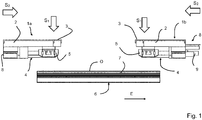
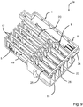
- FIG. 1 shows a sketch of a set of two complementary busbar connectors 1a, 1b recognize.
- the busbar connectors 1a, 1b each have an insulating housing 2, which is closed at the top with a cover 3.
- a first plug contact region 4 is formed with first plug contacts 5.
- This first plug contact region 4 and the first plug contacts 5 arranged thereon are designed such that the bus bar connector 1a, 1b can be plugged in each case with its first plug contact region 4 on the upper side O of a current-carrying profile 6 to lines accessible via gaps between webs 7 of the current-carrying profile with the first Plug contacts 5 electrically conductive contact.
- a second plug contact region 8 is formed with second plug contacts 9.
- the second plug-in contact regions 8 of the two complementary busbar connectors 1a, 1b are configured opposite and fitting to each other from the contour and from the position and design of the second plug contacts 9 so that a complementary pair of busbar connectors 1a, 1b with the respective second plug contact areas 8 inserted into each other can be to connect corresponding second plug contacts 9 of the two complementary busbar connectors 1a, 1b electrically conductive with each other.
- Part of the other part surrounds or whether the insulating material may be attached only dull one another. It is crucial that the complementary pair of busbar connectors 1a, 1b are formed by their second plug contact regions 8 so that an electrically conductive plug contact between the complementary busbar connectors 1a, 1b can be made to the second plug contact regions 8.
- the plug-in direction S2 of the second plug-in contact regions 8 is structurally predetermined such that it extends in the extension direction E of the current-carrying profile 6.
- the plug-in direction S1 of the first plug-in contact regions 4, however, is aligned vertically to the direction of longitudinal extension of the busbar connectors 1a, 1b and the extension direction E of the current-carrying profile 6 to be contacted.
- the first plug-in contacts 5 are adapted to this plug-in direction S1.
- the busbar connector 1a, 1b can be plugged in each case with its first plug contact region 4 on the upper side O of a respective current-carrying profile 6.
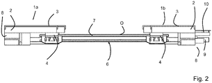
- FIG. 2 Leaves a side view of the set FIG. 1 detect. It is clear that now the busbar connectors 1a, 1b is plugged from the top O of the current-carrying profile 6 on this. The height is only slightly increased. On the front side of the current-carrying profiles 6, a plug-in connection for a complementary busbar connector 1a, 1b is then provided with the second plug-in contact regions 8 preferably in extension of the contacted lines (not visible) in the contacted current-carrying profile 6.
- the electrically conductive connection of two current-carrying profiles 6 is thus not simply by an axial direction, ie in the direction of extension E of the current-carrying profile 6 in this plugged busbar couplings.
- the lines of the current-carrying profile 6 are rather by plugging the busbar connector 1a, 1b contacted transversely to the extension direction E and it is created with the second plug contact area 8, an additional plug contact interface.
- a guide nose 10 is provided on the complementary busbar connector 1b at the first plug-in contact region, which facilitates the insertion and guiding of the complementary plug-in connector 1a into the plug-in position.
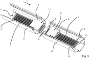
- FIG. 3 allows a perspective view of the complementary busbar connectors 1a, 1b in the plugged state to recognize a power guide profile 6.
- two current-carrying profiles 6 are arranged one behind the other in the extension direction E of the current-carrying profiles 6.
- a busbar connector 1a, 1b is plugged in each other in a complementary embodiment.
- the current-carrying profiles 6 have in the longitudinal direction E extending parallel to each other webs 7 with gaps 12 between the webs 7. At the webs 7 or at the bottom of the interstices 12 12 accessible lines 13 are arranged. These are contacted with the first plug contacts 5 of the first plug contact region 4 of the busbar connectors 1a, 1b electrically conductive.
- the two matching busbar connectors 1a, 1b can then be plugged together and contacted electrically conductive.
- two plug contacts 9 are provided, which are designed as blade contacts.
- the matching fork contacts are arranged in the plug contact openings in the insulating housing 3 of the left busbar connector 1a.
- FIG. 4 shows the perspective view FIG. 3 without metal trough 11. It is clear that on the side of the busbar connectors 1a, 1b in each case a grounding contact 14 protrudes.
- This ground contact 14 occurs when plugging the busbar connector 1a, 1b on the busbar 6 in electrically conductive contact with the surrounded metal trough 11, when the current-carrying profile 6 in FIG. 3 shown inserted into a metal trough 11.
- This plug-in contact 15 is designed to be leading and has a further from the busbar connector 1a, 1b outstanding length, as the other second plug contacts 9 in the second plug contact area.
- the grounding contact 14 is thereby separated from each other when the busbar connectors 1a, 1b are removed.
- FIG. 5 shows a perspective view of the pair of complementary busbar connectors 1a, 1b.
- the grounding contact 14 is designed with two projecting spring arms 16 in the opposite direction.
- the second plug contacts 5 are arranged on the webs 17, so that the first plug contact region 4 is designed to be plugged into a plugging direction S1 perpendicular to the surface at the top and bottom of the busbar connector 1a, 1b and its insulating housing 3.
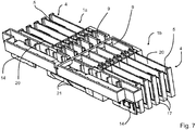
- FIG. 6 shows an opened at the top perspective view of a pair of busbar connectors 1a, 1b.
- a number of contact inserts 19 is present in the lower part 18 of the insulating housing 2. These each consist of a first plug contact 5 of the first plug contact region 4 and an opposite second plug contact 9 of the second plug contact region 8 and one of these two plug contacts 5, 9 interconnecting busbar piece 20th
- the second plug contacts 9 of the first busbar connector 1a are designed as fork contacts. They have two in one common root section interconnected forks, which are directed toward each other resiliently. The root area is a part of the busbar piece 20 or passes into this. Also, the ground contact terminal is provided on the opposite side of the ground contact 14 with such a fork contact 15 as a plug contact.
- the corresponding second busbar connector 1b has in its second plug-in contact region 8 a number of juxtaposed blade contacts for forming the second plug-in contacts 9.
- tongues 21 protrude obliquely on the side opposite from the insulating housing 2 of the two busbar connectors 1a, 1b on opposite sides. These serve to fix the busbar connector 1a, 1b to a metal trough 11, when the busbar connector 1a, 1b is attached to a arranged in the metal trough 11 current guide profile 6.
- FIG. 7 shows the pair of busbar connectors 1a, 1b FIG. 6 in the assembled state. It is clear that the trained in the form of blade contacts the second plug contacts 9 of the right busbar connector in the running as a fork contacts second plug contacts 9 of the left busbar connector 1a dive and contacted there by the fork contacts electrically conductive. It is clear that the tabs 21 are then arranged in alignment.
- FIG. 8 shows a cross-sectional view through a busbar connector 1 (either busbar connector 1a or complementary busbar connector 1b), which is inserted with its webs 17 in the interstices 12 between the webs 7 of the current-carrying profile 6.
- busbar connector 1 either busbar connector 1a or complementary busbar connector 1b
- electrical conductors 22 are arranged laterally. These are then contacted with associated first plug contacts 5 in the form of Federbügel- or Federarmtitleen electrically conductive.
- These first connector 5 are arranged on the webs 17 of the busbar connector 1 and protrude laterally resiliently thereof.
- a first plug contact 5 can be present on each side of the webs 17 of the busbar connector 1.
- the grounding contact 14 can optionally be contacted with an associated conductor 22 in the current-carrying profile 6 in an electrically conductive manner. This is preferred to keep the current paths for current drain short.
- busbar connector 1 with its first plug contact region 4 for plugging onto the top of the current-carrying profile 6, i. is formed on the open side of the spaces 12 and the ends of the webs 7 of the current-carrying profile 6.
- FIG. 9 shows a perspective view of an embodiment of a first busbar connector 1a with fork contacts for the second plug contacts 9. These are arranged on two levels in each case adjacent to each other, so as to increase the packing density.
- the lower part 18 of the insulating housing 2 takes on the contact inserts 19.
- the first plug contacts are arranged on the webs 17.
- intermediate walls 23 are provided to electrically isolate the individual juxtaposed plug-in contacts 9 from each other and to form individual chambers. At the top of these chambers are closed by the bottom 24 of a Isolierstoff Wenns 25, which is plugged onto the lower part 18 after inserting the lower contact inserts 19.
- the upper contact parts 19 are inserted into the insulating housing 18 and the Isolierstoffeinlegeteil 15 to arrange a number of second plug contact terminals 9 in the upper, second level.
- This Isolierstoffeinlegeteil 24 has from the bottom 24 downwardly projecting flanges 26, with which the available creepage distances and creepage distances can be further increased.
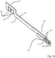
- FIG. 10 exemplifies a contact insert 19 for the lower level.
- the contact insert 19 for the upper level is constructed comparable to this.
- the first plug-in contact 5 has a spring tongue 27 (also called spring clip), which protrudes from a common busbar piece 20, which the fork contact 28 at the opposite end to the spring tongue 27 electrically conductively connects.
- the contact part 19 is integrally formed from a metal sheet. This can be done by punching and bending in a simple manner.
- the spring tongue 27 has on both sides contact edges 50, which can cut when plugging the first plug contact 5 on a current guide profile 6 in the line to be contacted 22. Thus, the first plug-in contact 5 is fixed in position to the line 22.
- the second plug contact 9 has a double fork contact with two pairs of mutually facing fork tongues 29, whose front free ends are turned away from each other. In this way, an insertion funnel for a corresponding blade contact is created.
- the busbar piece 20 has a bent bridge section 30, with which the opposite fork tongues 29 are connected to each other.
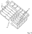
- FIG. 11 leaves a perspective view of the lower part 18 of the insulating housing for the busbar connector FIG. 9 detect.
- the spaced-apart intermediate walls 23 and webs 17 are clearly visible, each extending in the longitudinal direction of the insulating housing 3 and the lower part 18.
- the webs 17 are arranged laterally offset from the intermediate walls 23.
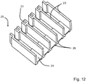
- FIG. 12 allows a perspective view of the Isolierstoffeinlegeteils 25 recognize. Again, intermediate walls 23 are arranged at a distance to each other, resting on a common floor 24. Also clear are the flanges 26 projecting from the base 24 on the side opposite the intermediate walls 23. A pair of juxtaposed parallel flanges 26 provide a space for receiving an intermediate wall 23 of the lower part 18 of the insulating housing 2.
- a receiving slot 31 for receiving a portion of the intermediate wall 23 or the end of a web 17 of the lower part 18 is provided on the back of the intermediate walls 23 respectively.
- the Isolierstoffeinlegeteil 25 can be pushed onto the lower part 18 and fixed in position there.
- FIG. 13 leaves a perspective view of the busbar connector 1a FIG. 9 recognize corresponding busbar connector 1b.
- the second plug contacts 9 are designed here as blade contacts. These are again arranged in groups next to each other and in two levels one above the other. Again, a Isolierstoffeinlegeteil 25 is provided, which is inserted into the lower part 18 of the insulating housing 2. In principle, reference may also be made here to the preceding statements.
- plug contours with chambers for receiving the second plug contacts 9 (designed here as blade contacts) are provided. These are then inserted into the chambers of the corresponding first connector 1a, wherein the fork contacts 28 then each encompass a blade contact 32 and electrically conductively contact.
- the first plug contact region 4 in turn has first plug contacts 5 with spring clips, as in the first exemplary embodiment.
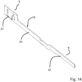
- FIG. 14 allows a perspective view of a Kunststoffinsatze 19 for this corresponding busbar connector 1b with blade contact 32 on a spring clip contact 27 on the opposite and recognize this first and second plug-in contact 9, 5 connecting busbar piece 20.
- the second plug contact 9 approximately at the height of the contact of the first plug contact 5 on the same mating plane, wherein the in FIG. 14 shown contact insert for use in the lower level of the busbar connector 1b is provided.
- FIG. 15 shows the lower part 18 of the previously described busbar connector 1b without insulating insert 25 but with inserted contact inserts 19, both in the lower, as well as in the upper level. It is clear that the busbar pieces 20, which connect the first and second plug-in contact 5, 9 with each other, are guided in a bend through the lower part 18. It is clear that the first plug contacts 5 fixed in position are inserted into the lower part 18. For this purpose, 18 suitable grooves are present in the lower part.
- the plug contacts 5 of the lower level lie on a side facing away from the web 17 side, on which the plug contacts 5 of the upper level are arranged.
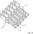
- FIG. 16 allows a perspective view of the Isolierstoffeinlegeteils 25 recognize.
- the air gaps and creepage distances between the adjacent second plug-in contacts 9 are substantially increased by the receiving fingers 34, which are separated from one another by intermediate gaps 33.
- This intermediate gap 33 serves to receive the intermediate walls 23 of the corresponding busbar connector 1a, when the busbar connector 1b is plugged onto the complementary busbar connector 1a.
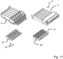
- FIG. 17 shows an exploded view of a four-part insulating housing 2 for a further embodiment of a busbar connector. Again, a lower part 18 is provided, which is covered by a cover part 3.
- the Isolierstoffeinlegeteil 25 is also made in two parts in this embodiment and consists of a lower part 35 and an upper part 36. These parts of the insulating housing 2 have contours for receiving the contact inserts 19 and to provide a plug contour in the second plug contact region 8 on the front side of the composite insulating 2.
- FIG. 18 shows the two different contact inserts 19, in this busbar connector 1 from FIG. 17 be used.
- the two different contact inserts 19 are shown in two orientations rotated by 180 degrees to each other.
- the lower contact insert 19 is the ground contact terminal with the grounding contact 14 on one side and a blade contact 32 on the opposite side, and a busbar piece 20 interconnecting these two contacts 14, 32.
- the other contacts have on one side a spring clip and on the opposite side a blade contact 32. Again, the first plug-in contact 5 and the opposite second plug-in contact 9 via a busbar piece 20 are interconnected. This has a U-shaped bend.
- FIG. 19 shows an exploded view of an insulating housing 2 also formed of four parts for the complementary busbar connector. To its construction can essentially refer to the description FIG. 9 to get expelled. Again, however, the Isolierstoffeinlegeteil 25 of two parts 35, 36 is formed.
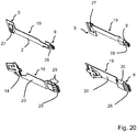
- FIG. 20 shows the measures provided for this busbar connector 1 contact inserts 19, each in two to 180 ° to each other rotated orientations.
- the contact inserts 19 in the upper area in turn have a spring tongue 27 to form the first plug contact 5 and on the opposite side a fork contact 28 to form the second plug contact 9.
- FIG. 10 shows the comments on FIG. 10 directed.
- the fork contact 28 is formed from three pairs of fork tongues 29 arranged one above the other.
- the contact force and the current cross-section is increased compared to the overlying contact parts 19, which is particularly important for the grounding contact.
- FIGS. 21 to 24 show the insulating housing 2 provided with the lower part 18 and cover 3 and the associated contact inserts 19 for the formation of single-row complementary busbar connectors 1a, 1b.
- These contact inserts 19 are comparable to the embodiment described above only with spatially slightly modified connection of the busbar piece 20 to the first plug-in contact connection 5 educated.
- FIG. 25 shows a detail view of a metal trough 11 with the current-carrying profile 6 accommodated therein.
- fasteners 37 are formed, for example in the form of protruding knobs. These fastening elements 37 are provided in order to fix a conductor rail connector 1 a, 1 b attached to the current-carrying profile 6 to the metal trough 11. This can be done by a locking connection, a screw connection or the like.
- the fasteners 37 may also be simply designed as holes for receiving tapping screws.
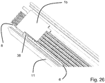
- FIG. 26 shows the snapshot view FIG. 25 with now plugged busbar connector 1b. It is clear that the busbar connector 1 b on one side has a mounting area with a matching to the fastening element 37 of the metal trough 11 fastener 38. For example, the busbar connector 1b can be latched to the metal trough 11.
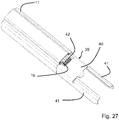
- FIG. 27 shows a perspective view of a metal trough 11 with a busbar connector 1b, which is plugged onto a non-visible current-carrying profile 6 in the metal trough 11.
- This busbar connector 1b is covered by a connecting element 39, more precisely with a retaining plate 40 of the connecting element 39.
- the connecting element 39 has opposite side guide wall sections 41, which are inserted on the left side in the profile of the metal trough 11, so that the connecting element is aligned in the alignment of the metal trough 11. Then, a further metal trough 11 with arranged thereon current guide profile 6 attached to the guide wall portions 41 and are pushed by means of the guide wall portions 41 to the underlying metal trough 11.
- busbar connector 1a A thereby already plugged onto the current guide profile 6 busbar connector 1a is guided in this way position and position correct to the busbar connector 1b, so that they enter into an electrically conductive plug contact during the sliding of two metal troughs 11.
- the busbar connector 1a, 1b also protrude a guide finger 42 which engages in a corresponding guide opening in the opposite, complementary busbar connector 1a, 1b.
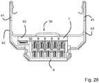
- FIG. 28 shows a cross-sectional view through the metal trough 11 from FIG. 27 , It is clear that the holding plate 40 rests on the top of the busbar connector 1 and this holds on the busbar 6.
- the guide wall sections 41 on the opposite sides then rest on the side walls 43 of the metal tray 11 and can also be guided into corresponding guide grooves or on the corresponding contours.
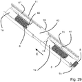
- FIG. 29 shows a perspective view of two in the direction of arrow to each other slidable metal troughs 11 with incorporated therein power guide profiles 6 and already before assembly to the current control profiles 6 plugged busbar connectors 1a, 1b.
- the connecting element 39 With the help of the connecting element 39, it is possible to keep not only the already plugged busbar connectors 1a, 1b on the support plate on the current guide profiles 6, but also with the help of the guide wall portions 41, the metal troughs 11 aligned to move toward each other. In this case, the already plugged busbar connectors 1a, 1b are fed to each other in the correct position and plugged into one another.
- tabs 44 are present, which can exert a spring pressure on the busbar connectors 1a, 1b and at least serve for improved introduction.
- FIG. 30 allows a view of a built-in a metal trough 11 power guide profile 6 with it plugged busbar connector 1 recognize. It is clear that the current-carrying profile 6 is covered on one side with a protective cap 45 on the front side.
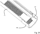
- FIG. 31 shows a cutaway view of a metal trough 11 with built-in power guide profile 6 and mounted thereon busbar connector 1.
- a protective cap 46 On the end of the metal trough 11, a protective cap 46 is pushed, the one Provides transport protection.
- This protective cap 46 may be provided for manual removal before plugging together second busbar connectors 1a, 1b. It is advantageous, however, if the protective cap 46 has a contour designed in such a way that the protective cap 46 automatically loosens and falls off when an adjacent metal trough 11 is attached or possibly only when a corresponding busbar connector 1a, 1b is attached.
- projecting webs 47 may be provided on the inside of the protective cap 46.
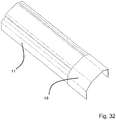
- FIG. 32 shows the metal trough 11 with end-pushed protective cap 46 from FIG. 31 facing the outside.
- the protective cap 46 is adapted to the cross-sectional contour of the metal trough 11.
- FIG. 33 shows a perspective view of the protective cap 46. It is clear that protrude at the opposite edge edges retaining tabs, which rest on the marginal edges of the metal trough 11 in the deferred state and hold the cap 46 to the metal trough 11. Visible are also stops 49 in the form of transverse webs, which form a stop for a metal trough 11 when the protective cap 46 is pushed onto the metal trough.
- FIG. 34 shows a variant of the busbar connectors 1a, 1b, in which the plug contacts 9 are rounded end.
- the plug contacts 9 can be arranged on two contact levels as shown.
- the rounded variant is basically independent of the number of insertion levels.
Abstract
Ein Stromschienenverbinder (1, 1 a, 1 b) zur elektrisch leitenden Verbindung von Leitungen (22) an Stegen (7) eines Stromführungsprofils (6), das ein Oberseite (O) hat, an der die Leitungen (22) über die Zwischenräume (12) zwischen den Stegen (7) zugänglich sind, wird beschrieben. Der Stromschienenverbinder (1, 1 a, 1 b) hat ein Isolierstoffgehäuse (2) und eine Mehrzahl von paarweise elektrisch leitend miteinander verbundenen ersten und zweiten Steckkontakten (4, 9). Es ist ein erster Steckkontaktbereich (4) mit den ersten Steckkontakten (5) zum Aufstecken auf die Oberseite (O) senkrecht zur Längserstreckungsrichtung (E) des Stromführungsprofils (6) in einer ersten Steckrichtung (S1) und zur Steckkontaktierung der Leitungen (22) des Stromführungsprofils (6) vorhanden. Weiterhin ist ein zweiter Steckkontaktbereich (8) an einer Stirnseite des Isolierstoffgehäuses (2) vorhanden, wobei der zweite Steckkontaktbereich (8) die zweiten Steckkontakte (9) zur Steckkontaktierung eines komplementären Steckverbinders (1, 1 a, 1 b) in eine der Längserstreckungsrichtung (E) des Stromführungsprofils (6) entsprechenden Steckrichtung (S2) hat. Die Ebene, welche die Oberseite (O) aufspannt, steht in einem Winkel zu einer die Stirnseite aufspannenden Ebene.A busbar connector (1, 1 a, 1 b) for the electrically conductive connection of lines (22) to webs (7) of a current-carrying profile (6), which has a top (O), at which the lines (22) via the intermediate spaces ( 12) between the webs (7) are accessible, will be described. The busbar connector (1, 1 a, 1 b) has a Isolierstoffgehäuse (2) and a plurality of pairwise electrically conductively interconnected first and second plug contacts (4, 9). It is a first plug contact region (4) with the first plug contacts (5) for attachment to the top (O) perpendicular to the longitudinal direction (E) of the current-carrying profile (6) in a first plug-in direction (S1) and plug-in contact of the lines (22) of the Stromführungsprofils (6) available. Furthermore, a second plug contact region (8) on one end side of the insulating material (2) is provided, wherein the second plug contact region (8) the second plug contacts (9) for plug contacting a complementary connector (1, 1 a, 1 b) in one of the longitudinal direction ( E) of the current-carrying profile (6) has the corresponding plug-in direction (S2). The plane which spans the top (O) is at an angle to a plane spanning the end face.
Description
Die Erfindung betrifft einen Stromschienenverbinder zur elektrisch leitenden Verbindung von Leitungen an Stegen eines Stromführungsprofils, das eine Oberseite hat, an der die Leitungen über die Zwischenräume zwischen den Stegen zugänglich sind, wobei der Stromschienenverbinder ein Isolierstoffgehäuse und eine Mehrzahl von paarweise elektrisch leitend miteinander verbundenen ersten und zweiten Steckkontakten hat.The invention relates to a busbar connector for electrically conductive connection of lines to webs of a current-carrying profile having an upper surface at which the lines are accessible via the spaces between the webs, wherein the busbar connector a Isolierstoffgehäuse and a plurality of pairs electrically conductively interconnected first and has second plug contacts.
Die Verbindung betrifft weiterhin ein Set aus zwei solchen komplementären Stromschienenverbindern und Metalltrögen mit jeweils darin aufgenommenem Stromführungsprofil.The compound further relates to a set of two such complementary busbar connectors and metal troughs, each with incorporated therein power guide profile.
Solche Stromführungsprofile werden insbesondere für Beleuchtungsanlagen in Gebäuden eingesetzt, um Leitungen zur Versorgung von Geräten, wie insbesondere von Leuchten oder sonstigen mit Energie und/oder Daten zu versorgenden Geräten kostengünstig und optisch ansprechend zu verlegen. Der Einbauort der Geräte kann dann flexibel entlang der Stromschiene gewählt und leicht variiert werden. Die Geräte können dann nicht nur einfach mit einem Steckverbinder auf einfache Weise elektrisch leitend mit den Leitungen an einem variabel festlegbaren Einbauort kontaktiert werden. Solche Stromschienensysteme haben auch den Vorteil, dass die Geräte zugleich mechanisch an der Stromschiene getragen werden können.Such current management profiles are used in particular for lighting systems in buildings, to lay cables for the supply of equipment, such as lights or other energy and / or data to be supplied devices cost and visually appealing. The installation location of the devices can then be selected flexibly along the busbar and varied slightly. The devices can then not only be easily contacted with a connector in a simple manner electrically conductive with the lines to a variably determinable installation location. Such busbar systems also have the advantage that the devices can be carried at the same time mechanically on the busbar.
Zur Verbindung mehrerer aneinander angrenzenden Stromführungsprofile wird z.B. in der
Als Alternative zu den axial in Erstreckungsrichtung der Stromführungsprofile einsteckbaren Stromschienenverbindern ist in der
In entsprechender Weise wird auch in
Bei der Montage der Stromführungsprofile, die in der Regel in einem Metalltrog aufgenommen sind, müssen erst einmal die Stromführungsprofile ausgerichtet und z.B. an einer Gebäudedecke befestigt werden. Anschließend erfolgt dann in einem separaten Schritt die elektrisch leitende Verbindung durch Aufstecken der Stromschienenverbinder. Dies ist arbeitsaufwändig und erfordert Fachpersonal.When mounting the current-carrying profiles, which are usually accommodated in a metal trough, once the current-carrying profiles have to be aligned, and e.g. be attached to a building ceiling. Subsequently, then in a separate step, the electrically conductive connection by attaching the busbar connectors. This is laborious and requires specialized personnel.
Ausgehend hiervon ist es daher Aufgabe der vorliegenden Erfindung, einen verbesserten Stromschienenverbinder zu schaffen, der bei einfachem Aufbau eine schnelle und fehlersichere Montage vorzugsweise bereits beim Aneinanderstecken von Stromführungsprofilen ermöglicht.Proceeding from this, it is therefore an object of the present invention to provide an improved busbar connector, which allows a quick and fail-safe assembly preferably already in the juxtaposition of current management profiles with a simple structure.
Die Aufgabe wird mit dem Stromschienenverbinder mit den Merkmalen des Anspruchs 1 sowie mit dem Set aus zwei komplementären Stromschienenverbindern und Metalltrögen mit jeweils daran aufgenommene Stromführungsprofil mit dem Merkmal des Anspruchs 14 gelöst. Vorteilhafte Ausführungsformen sind in den Unteransprüchen beschrieben.The object is achieved with the busbar connector having the features of
Beim gattungsgemäßen Stromschienenverbinder wird vorgeschlagen,
- dass ein erster Steckkontaktbereich mit den ersten Steckkontakten zum Aufstecken auf die Oberseite senkrecht zur Längserstreckungsrichtung des Stromführungsprofils in einer ersten Steckrichtung und zur Steckkontaktierung der Leitungen des Stromführungsprofils vorhanden ist, und
- dass ein zweiter Steckkontaktbereich an einer Stirnseite des Isolierstoffgehäuses vorhanden ist, wobei der zweite Steckkontaktbereich die zweiten Steckkontakte zur Steckkontaktierung eines komplementären Stromschienenverbinders in eine der Längserstreckungsrichtung des Stromführungsprofils entsprechenden zweiten Steckrichtung hat,
- wobei die Ebene, welche die Oberseite aufspannt, in einem Winkel zu einer die Stirnseite aufspannenden Ebene steht.
- that a first plug contact region with the first plug contacts for attachment to the top is provided perpendicular to the longitudinal extension direction of the current-carrying profile in a first plug-in direction and plug-in contact of the lines of the current-carrying profile, and
- a second plug-in contact region is provided on one end side of the insulating housing, wherein the second plug-in contact region has the second plug-in contacts for plug-in contact of a complementary busbar connector in a second plug-in direction corresponding to the longitudinal extension direction of the current-carrying profile,
- wherein the plane which spans the top is at an angle to a plane spanning the end face.
Dieser Winkel kann z.B. ein rechter Winkel sein, so dass die Ebenen annähernd lotrecht zueinander stehen.This angle can e.g. be a right angle, so that the levels are approximately perpendicular to each other.
Mit Hilfe des zweiten Steckkontaktbereichs des ersten Stromschienenverbinders wird eine Steckkontaktierung für einen komplementären Stromschienenverbinder bereitgestellt, der in axialer Richtung, d.h. in Richtung der Erstreckung der miteinander leitend zu verbindenden Stromführungsprofile auf den ersten Stromschienenverbinder aufgesteckt wird. Dann hat das Set von Stromschienenverbinder und komplementären Stromschienenverbinder drei Schnittstellen, wobei die voneinander beabstandeten ersten Steckkontaktbereiche eine Schnittstelle zum vertikalen Aufstecken auf die Stromführungsprofile und die zweiten Steckkontaktbereiche eine Schnittstelle zum axialen Aufeinanderstecken der Stromschienenverbinder bereitstellt.By means of the second plug contact region of the first bus bar connector, a plug contact for a complementary bus bar connector is provided, which in the axial direction, i. is plugged onto the first busbar connector in the direction of the extension of the current-carrying profiles to be connected to one another in a conductive manner. Then, the set of bus bar connectors and complementary bus bar connectors has three interfaces, the spaced apart first plug contact areas providing an interface for vertically plugging onto the current routing profiles and the second plug contact areas providing an interface for axially mating the bus bar connectors.
Während im Stand der Technik entweder längenveränderliche fertig montierte Stromschienenverbinder mit zwei voneinander beabstandeten Steckkontaktbereichen zum Aufstecken auf ein Stromführungsprofil oder Stromschienenkupplungen zum axialen Einstecken in einer Flucht nebeneinander angeordneten Stromführungsprofile vorhergesehen sind, wird nun ein anderer Weg vorgeschlagen.While in the prior art either variable-length fully assembled busbar connectors with two spaced plug contact areas for plugging on a power guide rail or busbar couplings for axial insertion in a juxtaposed power guide profiles are anticipated, another way is now proposed.
Es wird zur elektrischen Verbindung der Stromführungsprofile das Prinzip des vertikalen Aufsteckens auf einen ersten Steckkontaktbereich mit ersten Steckkontakten zur Steckkontaktierung der Leitung des Stromführungsprofils genutzt, wobei der Stromschienenverbinder auf die Oberseite des Stromführungsprofils aufgesteckt wird. Damit wird ermöglicht, dass sich die ersten Steckkontakte axial in Erstreckungsrichtung der Leitungen unbeweglich mit den Leitungen verkrallen können. Der Langzeitkontakt wird damit wesentlich verbessert und insbesondere einer Bildung von Oxidschichten mit der damit einhergehenden Erhöhung der Übergangswiderstände entgegengewirkt.It is the principle of vertical Aufsteckens on a first plug contact area with first plug contacts for electrical connection of the current-carrying profiles used for plug contacting the line of the current-carrying profile, wherein the busbar connector is attached to the top of the current-carrying profile. This makes it possible that the first plug contacts can dig in the direction of extension of the lines immovably with the lines. The long-term contact is thus significantly improved and counteracted in particular a formation of oxide layers with the concomitant increase in contact resistance.
Zusätzlich wird allerdings dann auch eine Schnittstelle zur axialen Steckverbindung mit den zweiten Steckkontaktbereichen bereitgestellt. Dies hat wie bei den Stromschienenkupplungen den Vorteil, dass eine elektrisch leitende Verbindung von hintereinander in einer Flucht anzuordnender Stromführungsprofile direkt im Schritt des Aneinanderreihens von Stromführungsprofiles hergestellt werden kann. Diese elektrisch leitende Verbindung wird aber nicht durch Steckkontaktierung der Leitung der Stromführungsprofile in axialer Richtung realisiert, sondern durch eine weitere Steckverbindung, die in Erstreckungsrichtung der Stromführungsprofile, d.h. in axialer Richtung wirkt. Durch die zweiten Steckkontakte kann dabei ein zuverlässiger, langzeitstabiler Kontakt am Stromschienenverbinder selbst bereitgestellt werden. Die Kontaktbedingungen werden damit ausschließlich durch die Stromschienenverbinder vorgegeben und sind nicht von den Bedingungen des Stromführungsprofils abhängig.In addition, however, an interface to the axial plug connection with the second plug contact regions is then also provided. As with the busbar couplings, this has the advantage that an electrically conductive connection of current-conducting profiles to be arranged one behind the other can be produced directly in the step of juxtaposing current-carrying profiles. However, this electrically conductive connection is not realized by plug-contacting the line of the current-carrying profiles in the axial direction, but by a further connector, in the extension direction of the current-carrying profiles, i. acts in the axial direction. By the second plug contacts can be provided on the busbar connector itself a reliable, long-term stable contact. The contact conditions are thus specified solely by the busbar connectors and are not dependent on the conditions of the current-carrying profile.
Anders als beim Abgriff zum Anschluss von Geräten an ein Stromführungsprofil sind an die elektrisch leitende Verbindung der Leitungen von Stromführungsprofilen miteinander größere Anforderungen zu stellen. Die dort fließenden Ströme sind in der Regel nämlich wesentlich höher, als die in ein einzelnes Gerät abfließenden Ströme. Zudem wirken sich Wärmeausdehnungen der Leitungen bei der Verbindung aufeinanderfolgende Stromführungsprofile auf die Zuverlässigkeit der Steckkontaktierung aus. Eine Bewegung der Steckkontakte relativ zum Leiter kann bereits bei sehr geringen Bewegungen zu Reibkorrosion und dem Aufbau von Oxidschichten führen, was zur hochohmigen Verbindung und Wärmeentwicklung führt. Dem kann durch die Nutzung von auf die Oberseite des Stromführungsprofils aufsteckbaren ersten Steckkontaktbereichen auf einfache und sichere Weise entgegengewirkt werden. Dem sich hieraus ergebenden Nachteil, dass die Stromschienenverbinder dann erst nachträglich nach der Installation der Stromführungsprofile auf diese aufgesteckt werden können, wird durch die Bereitstellung einer zusätzlichen Schnittstelle zur axialen Steckkontaktierung über die zweiten Steckkontaktbereiche entgegengewirkt.Unlike the tap for connecting devices to a current-carrying profile, greater demands are placed on the electrically conductive connection of the lines of current-carrying profiles. The currents flowing there are, as a rule, much higher than the currents flowing into a single device. In addition, thermal expansions of the lines during the connection of successive current-carrying profiles affect the reliability of the plug-in contact. A movement of the plug contacts relative to the conductor can lead to fretting corrosion and the formation of oxide layers even at very low movements, which leads to the high-resistance connection and heat generation. This can be counteracted by the use of attachable to the top of the power guide profile first plug contact areas in a simple and secure way. Himself resulting disadvantage that the busbar connectors can then be plugged subsequently only after the installation of the current-carrying profiles, is counteracted by providing an additional interface to the axial plug contact via the second plug contact areas.
Die zweiten Steckkontakte des zweiten Steckkontaktbereichs können als Messerkontakte und/oder Gabelkontakte ausgeführt sein. So können die zweiten Steckkontakte des ersten Stromschienenverbinders als Messerkontakte und die Steckkontakte eines komplementären Stromschienenverbinders als Gabelkontakte ausgeführt sein. Denkbar ist aber auch eine Kombination derart, dass ein Steckverbinder für mehrere zweite Steckkontakte eine Variation von Messer- und Gabelkontakten und der komplementäre Steckverbinder, der zum Aufstecken auf den Steckverbinder vorgesehen ist, eine entsprechend hieran angepasste komplementäre Variation von Gabel- und Messerkontakten aufweist. Weiterhin ist auch ein hermaphroditischer Steckkontakt mit Messer- und/oder Gabelkontakten denkbar.The second plug contacts of the second plug contact region can be designed as blade contacts and / or fork contacts. Thus, the second plug contacts of the first bus bar connector can be designed as blade contacts and the plug contacts of a complementary bus bar connector as fork contacts. However, a combination is also conceivable such that a connector for a plurality of second plug contacts has a variation of blade and fork contacts and the complementary plug connector, which is provided for plugging onto the plug connector, has a correspondingly matched complementary variation of fork and blade contacts. Furthermore, a hermaphroditic plug contact with blade and / or fork contacts is conceivable.
Die Steckverbindung von zwei Stromschienenverbindern mit Hilfe von Messer- und Gabelkontakten ermöglicht einen zuverlässigen Steckkontakt auch für hohe Ströme, der langzeitstabil ist und sich einfach und zuverlässig realisieren lässt. Die Messer- und Gabelkontakte sind zudem sehr kompakt ausführbar.The plug-in connection of two busbar connectors with the aid of blade and fork contacts enables a reliable plug-in contact even for high currents, which is long-term stable and can be implemented easily and reliably. The knife and fork contacts are also very compact executable.
Die ersten Steckkontakte zum Aufstecken auf die Stromführungsprofile und Kontaktierung an Stegen der Stromführungsprofile angeordnete Leitungen können jeweils zumindest eine Federzunge aufweisen. Damit wird eine elektrisch leitende Kontaktierung des Stromschienenverbinders mit Leitungen durch Ausnutzung von Federkräften der Federzungen ermöglicht. Während bei Gabelzungen von zwei Gabelzinken aufeinander zuweisende Kräfte auf den zwischenliegenden Messerkontakt ausgeübt werden, wird bei den Federzungen nur von einer Seite eine Kontaktkraft auf die zu kontaktierende Leitung ausgeübt.The first plug-in contacts for plugging on the current-carrying profiles and contacting on webs of the current-carrying profiles arranged lines may each have at least one spring tongue. This allows an electrically conductive contacting of the busbar connector with lines by utilizing spring forces of the spring tongues. While in forks of two forks successive forces are exerted on the intermediate blade contact, the contact force is exerted on the line to be contacted only one side of the spring tongues on one side.
Die Federzungen können zumindest eine seitlich vorstehende Kontaktkante haben. Dies hat den Vorteil, dass sich die Federzungen beim Aufstecken in den zu kontaktierenden Leitungen des Stromführungsprofils verkrallen. Damit kann eine Relativbewegung der Steckkontakte zu den Leitungen entlang der Erstreckungsrichtung der Leitungen auf einfache Weise unterbunden werden.The spring tongues may have at least one laterally projecting contact edge. This has the advantage that the spring tongues when plugging in to be contacted Claw lines of the current-carrying profile. Thus, a relative movement of the plug contacts to the lines along the extension direction of the lines can be prevented in a simple manner.
An dem ersten Steckkontaktbereich können Stege ausgebildet sein, die zum Einstecken in den Zwischenraum benachbarter Stege des Stromführungsprofils vorgesehen sind und jeweils die ersten Steckkontakte tragen, wobei beidseits des Steges jeweils ein Steckkontakt angeordnet sein kann. Diese Stege dienen somit zur Aufnahme der ersten Steckkontakte und zur Führung des Stromschienenverbinders mit seinem ersten Steckkontaktbereich in den Zwischenraum zwischen den Stegen des zu kontaktierenden Stromführungsprofils hinein, wenn der Stromschienenverbinder an der Oberseite auf das Stromführungsprofil aufgesteckt wird. Zudem stellen die Stege eine elektrische Isolation benachbarter Steckkontakte sicher.At the first plug contact region webs may be formed, which are provided for insertion into the intermediate space of adjacent webs of the current-carrying profile and in each case carry the first plug contacts, wherein on both sides of the web in each case a plug contact can be arranged. These webs thus serve to receive the first plug contacts and to guide the busbar connector with its first plug contact area into the space between the webs of the current guide profile to be contacted, when the busbar connector is attached to the top of the current-carrying profile. In addition, the webs ensure electrical insulation of adjacent plug contacts.
Die zweiten Steckkontakte können dann in Steckrichtung beweglich in dem Isolierstoffgehäuse gelagert sein. Dies hat den Vorteil, dass Relativbewegungen der in einer Flucht hintereinander angeordneten Stromführungsprofile an der Schnittstelle zwischen dem Stromschienenverbinder und dem daran aufgesteckten komplementären Stromschienenverbinder im zweiten Steckkontaktbereich ausgeglichen werden. Die Steckkontaktierung der zweiten Steckkontakte des Stromschienenverbinders und des daran aufgesteckten komplementären Stromschienenverbinders wird bei einer solchen axialen Bewegung nicht beeinträchtigt. Der Längenausgleich erfolgt dann jeweils in der Verbindung der beweglich gelagerten zweiten Steckkontakte mit den zugeordneten ersten Steckkontakten desselben Stromschienenverbinders. Dabei kann das gesamte Kontaktpaar bestehend aus den paarweise elektrisch leitend miteinander verbundenen ersten und zweiten Steckkontakten und dem zwischenliegenden Stromschienenstück beweglich in dem Isolierstoffgehäuse aufgenommen sein. Damit wird sichergestellt, dass sich jedes der Steckkontakte eines Kontaktpaares unabhängig voneinander bewegen kann, wenn sich einzelne Leitungen in dem Stromführungsprofil unterschiedlich zueinander ausdehnen.The second plug contacts can then be mounted movably in the plug-in direction in the insulating material. This has the advantage that relative movements of the current routing profiles arranged in alignment one behind the other at the interface between the busbar connector and the complementary busbar connector attached thereto in the second plug-in contact region are compensated. The plug-in contact of the second plug contacts of the busbar connector and the plugged complementary busbar connector is not affected in such axial movement. The length compensation then takes place in each case in the connection of the movably mounted second plug contacts with the associated first plug contacts of the same busbar connector. In this case, the entire pair of contacts consisting of the electrically conductive interconnected first and second plug contacts and the intermediate busbar piece may be movably received in the insulating material. This ensures that each of the plug contacts of a contact pair can move independently of each other, if individual lines in the current guide profile extend different from each other.
Die Paare von ersten und zweiten Steckkontakten können über ein Stromschienenstück oder eine flexible Leitung miteinander verbunden sein. Das Stromschienenstück kann dabei einen flexiblen, z.B. mäanderförmigen Abschnitt haben, um einen Längentoleranzausgleich bereitzustellen. Das Stromschienenstück kann aber auch mehrteilig sein und eine Kupplung zum Ausgleich von Bewegungen in axialer Richtung bei Sicherstellung eines guten Kontakts haben.The pairs of first and second plug contacts may be connected to each other via a bus bar piece or a flexible line. The busbar piece may be a flexible, e.g. meandering section to provide a length tolerance compensation. But the busbar piece can also be multi-part and have a coupling to compensate for movements in the axial direction while ensuring a good contact.
Die Paare von ersten und zweiten Steckkontakten können einstückig mit einem die Steckkontakte verbindenden Stromschienenstück gebildet sein. Sie können dann einfach als z.B. aus einem Metallblech ausgeformtes Teil in das Isolierstoffgehäuse eingelegt werden. Dies ermöglicht eine einfache Montage und einen zuverlässigen Aufbau des Stromschienenverbinders.The pairs of first and second plug contacts may be integrally formed with a busbar piece connecting the plug contacts. You can then simply as e.g. From a sheet metal molded part are inserted into the insulating material. This allows easy installation and a reliable construction of the busbar connector.
Das Isolierstoffgehäuse kann Befestigungselemente oder Befestigungskonturen zur Fixierung an dem Stromführungsprofil oder einem das Stromführungsprofil tragenden bzw. aufnehmenden Metalltrog haben. Damit wird der Gefahr weiter vorgebeugt, dass sich die am ersten Steckkontaktbereich vorhandenen Kontakte relativ zu den Leitungen des Stromführungsprofils bewegen. Der Stromschienenverbinder wird auf diese Weise ortsfest mit dem zugeordneten Stromführungsprofil verbunden, auf das der Stromschienenverbinder aufgesteckt ist. Alternativ erfolgt die Festlegung mit dem das Stromführungsprofil aufnehmenden Metalltrog.The insulating housing may have fastening elements or fastening contours for fixing to the current-carrying profile or a metal trough carrying or receiving the current-carrying profile. This further avoids the danger that the contacts present on the first plug-in contact area move relative to the lines of the current-carrying profile. The busbar connector is fixedly connected in this way with the associated current-carrying profile, to which the busbar connector is attached. Alternatively, the determination takes place with the metal trough receiving the current-carrying profile.
Weiterhin ist es denkbar, dass der Stromschienenverbinder eine Schutzkappe zur Abdeckung des zweiten Steckkontaktbereiches hat. Damit ist ein Transportschutz vorhanden, der bei der Montage der Lichtbänder entfernt werden kann. Diese Schutzkappe kann eine zum selbsttätigen Lösen der Schutzkappe von dem zweiten Steckkontaktbereich beim Aufstecken des komplementären Stromschienenverbinders auf den zweiten Steckkontaktbereich ausgebildete Kontur haben. Damit wird auf jeden Fall sichergestellt, dass eine Berührung der zweiten Steckkontakte im zweiten Steckkontaktbereich unmöglich ist, auch wenn der Stromschienenverbinder auf ein Stromführungsprofil aufgesteckt ist. Diese Schutzkappe wird dann erst beim Aufstecken eines komplementären Stromschienenverbinders entfernt. Dieses erfolgt aber auch nicht einfach manuell mit der Folge, dass die zweiten Steckkontakte dann doch noch temporär nicht berührungsgeschützt wären. Vielmehr wird durch eine geeignete Kontur der Schutzkappe sichergestellt, dass sie sich selbsttätig beim Aufstecken des komplementären Stromschienenverbinders von dem zweiten Steckkontaktbereich löst. Dies kann durch eine Rastverbindung und Führungsvorsprünge realisiert sein, die mit dem komplementären Stromschienenverbinder und/oder dem Stromführungsprofil und/oder dem Metalltrog zusammenwirken, der dann die Rastverbindung aufhebt und durch den Aufschiebevorgang die Schutzkappe von dem zweiten Steckkontaktbereich wegbewegt.Furthermore, it is conceivable that the busbar connector has a protective cap for covering the second plug contact area. Thus, a transport protection is available, which can be removed during assembly of the light strips. This protective cap can have a contour designed to automatically release the protective cap from the second plug contact region when the complementary bus bar connector is plugged onto the second plug contact region. This ensures in any case that a touch of the second plug contacts in the second plug contact area is impossible, even if the busbar connector is plugged onto a power guide profile. This protective cap is then removed only when attaching a complementary busbar connector. But this is not easy manually with the result that the second plug contacts then still temporarily not protected against touch. Rather, it is ensured by a suitable contour of the cap, that it dissolves automatically when attaching the complementary busbar connector from the second plug contact area. This can be realized by a latching connection and guide projections which cooperate with the complementary busbar connector and / or the current-carrying profile and / or the metal trough, which then cancels the snap-in connection and moves the protective cap away from the second plug-in contact region by the pushing-on process.
Der zweite Steckkontaktbereich kann ohne Rastmittel zur beweglichen Steckverbindung der Isolierstoffgehäuse und der darin aufgenommenen zweiten Steckkontakte des Stromschienenverbinders und eines komplementären Stromschienenverbinders ausgebildet sein. Dies hat den Vorteil, dass die Steckverbindung zwischen Stromschienenverbinder und komplementären Stromschienenverbinder in axialer Richtung beweglich bleibt. Damit ist ein Toleranzausgleich in der Verbindung der zweiten Steckkontakte miteinander sichergestellt.The second plug contact region can be formed without latching means for the movable plug connection of the insulating material housing and the second plug contacts of the busbar connector and a complementary busbar connector received therein. This has the advantage that the plug connection between the busbar connector and the complementary busbar connector remains movable in the axial direction. For a tolerance compensation in the connection of the second plug contacts is ensured with each other.
Elektrisch voneinander getrennte zweite Steckkontakte eines Stromschienenverbinders, die zur Kontaktierung voneinander unterschiedliche Leitungen des Stromführungsprofils vorgesehen sind, können in zwei Ebenen übereinander angeordnet sein. Der zweite Steckkontaktbereich hat dann ein Isolierstoffeinlegeteil mit einem die beiden Ebenen voneinander abtrennenden Boden und mit Trennwänden zwischen in einer gemeinsamen Ebene nebeneinander angeordneten zweiten Steckkontakten. Auf diese Weise kann der zweite Steckkontaktbereich sehr kompakt ausgestaltet werden. Mithilfe des zusätzlichen Isolierstoffeinlegeteils gelingt es dann, die erforderlichen Luft- und Kriechstrecken zwischen den neben- und übereinander angeordneten zweiten Steckkontakten bereitzustellen und eine schnelle und einfache Montage der zweiten Steckkontakte in dem Isolierstoffgehäuse zu ermöglichen.Electrically separated second plug contacts of a busbar connector, which are provided for contacting different lines of the current-carrying profile, can be arranged one above the other in two planes. The second plug contact region then has an insulating insert with a bottom separating the two planes and with partitions between second plug contacts arranged side by side in a common plane. In this way, the second plug contact region can be made very compact. Using the additional Isolierstoffeinlegeteils then manages to provide the required clearance and creepage distances between the juxtaposed and stacked second plug contacts and to allow quick and easy installation of the second plug contacts in the insulating material.
Der Stromschienenverbinder kann einen voreilenden Erdungskontaktanschluss mit einem an einer Seitenwand des Isolierstoffgehäuses zur Steckkontaktierung eines Metalltrogs, in dem das Stromführungsprofil aufgenommen ist, haben, wenn der Stromschienenverbinder auf das im Metalltrog angeordnete Stromführungsprofil aufgesteckt ist. Mithilfe dieses zusätzlichen Erdungskontaktanschlusses wird eine durchgehende Erdung des Metalltrogs auf einfache und zuverlässige Weise sichergestellt. Der Erdungskontaktanschluss kontaktiert den Metalltrog beim Aufstecken des Stromschienenverbinders auf das Stromführungsprofil dann mit dem an der Seitenwand des Isolierstoffgehäuses vorhandenen Erdungskontakt.The bus bar connector may have a leading ground contact terminal with one on a side wall of the insulating housing for plug contacting a metal trough, in which the current-carrying profile is accommodated, when the Busbar connector is attached to the arranged in the metal trough power guide profile. This additional earthing contact terminal ensures a continuous grounding of the metal trough in a simple and reliable manner. The ground contact terminal then contacts the metal trough when plugging the busbar connector onto the current-carrying profile with the grounding contact present on the side wall of the insulating housing.
Der oben beschriebene Stromschienenverbinder stellt als Set aus zwei komplementären Stromschienenverbindern, die über ihre zweiten Steckkontaktbereiche miteinander steckkontaktiert werden, eine elektrisch leitende Verbindung zwischen zwei in einer Flucht hintereinander angeordneten Stromführungsprofilen bereit. Diese Stromführungsprofile sind in der Regel in einem Metalltrog aufgenommen.The busbar connector described above provides as a set of two complementary busbar connectors, which are plugged into each other via their second plug contact areas, an electrically conductive connection between two in a run successively arranged current guide profiles ready. These current-carrying profiles are usually taken in a metal trough.
Zur mechanischen Verbindung der in einer Flucht hintereinander angeordneten Metalltröge kann ein Verbindungselement vorhanden sein, das Führungsabschnitte zum Einschieben in zwei miteinander zu verbindenden Metalltröge aufweist. Das Verbindungselement kann zusätzlich noch eine Halteplatte zur Auflage auf den Stromschienenverbindern und zur Führung eines auf ein Stromführungsprofil eines ersten Metalltrogs aufgesteckten Stromschienenverbinders zum zweiten Steckkontaktbereich eines auf ein Stromführungsprofil eines zweiten Metalltrogs aufgesteckten komplementären Stromschienenverbinders haben. Mithilfe eines solchen Verbindungselementes gelingt es somit nicht nur, die in Längserstreckungsrichtung der Metalltröge hintereinander angeordneten Metalltröge mechanisch miteinander zu verbinden. Vielmehr kann mithilfe der Halteplatte auch der Stromschienenverbinder vor einem Abrutschen an der Oberseite des Stromschienenführungsprofils gehalten werden. Zudem wird mit der Halteplatte eine Führung der miteinander über ihre zweiten Steckkontaktbereiche zu kontaktierenden Stromschienenverbinder aufeinander erreicht.For the mechanical connection of the metal troughs, which are arranged one after the other in alignment, a connecting element may be present which has guide sections for insertion into two metal troughs to be connected to one another. The connecting element may additionally have a retaining plate for resting on the busbar connectors and for guiding a busbar connector plugged onto a current-carrying profile of a first metal trough to the second plug-in contact region of a complementary busbar connector plugged onto a current-carrying profile of a second metal trough. With the help of such a connecting element, it is thus not only possible to mechanically connect the metal troughs arranged one behind the other in the longitudinal direction of the metal troughs. Rather, by means of the retaining plate and the busbar connector can be prevented from slipping on the top of the busbar guide profile. In addition, with the retaining plate, a guidance of the busbar connectors to be contacted with one another via their second plug contact regions is achieved.
Die Erfindung wird nachfolgend anhand von Ausführungsbeispielen mit den beigefügten Zeichnungen näher erläutert. Es zeigen:
Figur 1- - Seitenansicht eines Sets aus zwei Stromschienenverbindern und einer Stromschiene;
Figur 2- -
Set aus Figur 1 im aufgesteckten Zustand der Stromschienenverbinder; Figur 3- - Perspektivische Ansicht eines Sets aus zwei Stromschienenverbindern und zwei Metalltrögen mit darin jeweils aufgenommenen Stromführungsprofilen;
Figur 4- - Perspektivische Ansicht zweier komplementärer Stromschienenverbinder, die jeweils auf ein Stromführungsprofil aufgesetzt sind;
Figur 5- - Perspektivische Ansicht von zwei komplementären Stromschienenverbindern;
Figur 6- - Perspektivische Ansicht des Stromführungsverbinders aus
Figur 5 im geöffneten Zustand ohne Abdeckung; Figur 7- - Perspektivische Ansicht der Stromschienenverbinder aus
Figur 6 im zusammengesteckten Zustand; Figur 8- - Querschnittsansicht durch einen auf ein Stromführungsprofil aufgesteckten und mit einem Metalltrog elektrisch leitend verbundenen Stromschienenverbinder;
Figur 9- - Perspektivische Ansicht einer Ausführungsform eines Stromschienenverbinders im geöffneten Zustand;
Figur 10- - Perspektivische Ansicht eines Steckverbinderpaares für den
Stromschienenverbinder aus Figur 9 ; Figur 11- - Perspektivische Ansicht des Isolierstoffgehäuses des Stromschienenverbinders aus
Figur 9 und 10 ; Figur 12- - Perspektivische Ansicht eines Isolierstoffeinlegeteils für den
Stromschienenverbinder aus Figur 9 und 10 ; Figur 13- - Perspektivische Ansicht eines komplementären Stromschienenverbinders im geöffneten Zustand;
Figur 14- - +Perspektivische Ansicht eines Steckverbinderpaares für den
Stromschienenverbinder aus Figur 13 ; Figur 15- - Perspektivische Ansicht des Isolierstoffgehäuses des Stromschienenverbinders aus
Figur 13 mit eingelegten Stromschienenpaaren; Figur 16- - Perspektivische Ansicht eines Isolierstoffeinlegeteils für den
Stromschienenverbinder aus Figur 15 ; Figur 17- - Explosionsansicht des aus vier Einzelteilen bestehenden Isolierstoffgehäuses für eine andere Ausführungsform eines Stromschienenverbinders;
Figur 18- - Perspektivische Ansicht von vier unterschiedlichen Steckverbinderpaaren für den
Stromschienenverbinder aus Figur 17 ; Figur 19- - Perspektivische Ansicht des aus vier Teilen gebildeten Isolierstoffgehäuses eines weiteren Steckverbinders;
Figur 20- - Perspektivische Ansicht von vier unterschiedlichen Steckverbinderpaaren für den
Stromschienenverbinder aus Figur 19 ; Figur 21- - Perspektivische Ansicht des Ober- und Unterteils eines Isolierstoffgehäuses für eine weitere Ausführungsform eines Stromschienenverbinders mit einer Anschlussebene;
Figur 22- - Perspektivische Ansicht des Steckverbinderpaares in jeweils zu 180 Grad zueinander verdrehter Anordnung für den
Stromschienenverbinder aus Figur 21 ; Figur 23- - Perspektivische Ansicht des Ober- und Unterteils des Isolierstoffgehäuses für einen komplementären Stromschienenverbinder;
Figur 24- - Perspektivische Ansicht des Steckverbinderpaares in jeweils zu 180 Grad zueinander verdrehter Anordnung für den
Stromschienenverbinder aus Figur 23 ; Figur 25- - Perspektivische Ausschnittsansicht eines Metalltrogs mit darin angeordnetem Stromführungsprofil und Befestigungselementen an dem Metalltrog zur Fixierung eines Stromschienenverbinders;
Figur 26- - Perspektivische Ansicht des Metalltrogs mit Stromführungsprofil und darauf aufgestecktem Steckverbinder mit Befestigungselement zur Befestigung an dem Metalltrog;
Figur 27- - Perspektivische Ansicht eines Metalltrogs mit auf ein Stromführungsprofil im Metalltrog aufgesteckten Stromschienenverbinder und zusätzlichem Verbindungselement;
Figur 28- - Querschnittsansicht durch den
Metalltrog aus Figur 27 und mit dem Verbindungselement; Figur 29- - Perspektivische Ansicht von zwei in Pfeilrichtung aufeinander schiebbaren Metalltrögen und mit Verbindungselement;
Figur 30- - Perspektivische Ansicht eines Metalltrogs mit Stromführungsprofil und endseitiger Schutzkappe auf dem Stromführungsprofil;
Figur 31- - Ausschnittansicht eines Metalltroges mit darauf aufgeschobener Schutzkappe;
Figur 32- - Perspektivische Ansicht des Metalltroges mit endseitig aufgeschobener Schutzkappe aus
Figur 31 mit Blick auf die Außenseite; Figur 33- - Perspektivische Ansicht der Schutzkappe;
Figur 34- - Variante der Stromschienenverbinder mit endseitig abgerundeten Steckkontakten.
- FIG. 1
- - Side view of a set of two busbar connectors and a busbar;
- FIG. 2
- - Set off
FIG. 1 in the plugged state, the busbar connector; - FIG. 3
- - Perspective view of a set of two busbar connectors and two metal troughs with therein each incorporated power management profiles;
- FIG. 4
- - Perspective view of two complementary busbar connectors, which are each placed on a power guide profile;
- FIG. 5
- - Perspective view of two complementary busbar connectors;
- FIG. 6
- - Perspective view of the power line connector
FIG. 5 in the opened state without cover; - FIG. 7
- - Perspective view of the busbar connector
FIG. 6 in the assembled state; - FIG. 8
- - Cross-sectional view through a plugged onto a current-carrying profile and electrically connected to a metal trough busbar connector;
- FIG. 9
- - Perspective view of an embodiment of a busbar connector in the open state;
- FIG. 10
- - Perspective view of a connector pair for the busbar connector
FIG. 9 ; - FIG. 11
- - Perspective view of the insulating material of the busbar connector
FIG. 9 and10 ; - FIG. 12
- - Perspective view of an Isolierstoffeinlegeteils for the busbar connector
FIG. 9 and10 ; - FIG. 13
- - Perspective view of a complementary busbar connector in the open state;
- FIG. 14
- - + Perspective view of a connector pair for the busbar connector
FIG. 13 ; - FIG. 15
- - Perspective view of the insulating material of the busbar connector
FIG. 13 with inserted busbar pairs; - FIG. 16
- - Perspective view of an Isolierstoffeinlegeteils for the busbar connector
FIG. 15 ; - FIG. 17
- - Exploded view of the four-part insulating material housing for another embodiment of a busbar connector;
- FIG. 18
- - Perspective view of four different connector pairs for the busbar connector
FIG. 17 ; - FIG. 19
- - Perspective view of the formed of four parts Isolierstoffgehäuses another connector;
- FIG. 20
- - Perspective view of four different connector pairs for the busbar connector
FIG. 19 ; - FIG. 21
- - Perspective view of the upper and lower part of an insulating housing for a further embodiment of a busbar connector with a connection plane;
- FIG. 22
- - Perspective view of the connector pair in each case to 180 degrees to each other twisted arrangement of the busbar connector
FIG. 21 ; - FIG. 23
- - Perspective view of the upper and lower part of the insulating housing for a complementary busbar connector;
- FIG. 24
- - Perspective view of the connector pair in each case to 180 degrees to each other twisted arrangement of the busbar connector
FIG. 23 ; - FIG. 25
- - Perspektivische detail view of a metal trough with disposed therein power guide profile and fasteners on the metal trough for fixing a busbar connector;
- FIG. 26
- - Perspective view of the metal trough with current carrying profile and plugged-on connector with fastener for attachment to the metal trough;
- FIG. 27
- - Perspective view of a metal trough mounted on a current-carrying profile in the metal trough busbar connector and additional connecting element;
- FIG. 28
- - Cross-sectional view through the metal trough
FIG. 27 and with the connecting element; - FIG. 29
- - Perspective view of two successive slidable in the direction of the arrow metal troughs and with connecting element;
- FIG. 30
- - Perspective view of a metal trough with current-carrying profile and end cap on the power supply profile;
- FIG. 31
- - Detail view of a metal trough with protective cap pushed onto it;
- FIG. 32
- - Perspective view of the metal trough with end-pushed protective cap
FIG. 31 facing the outside; - FIG. 33
- - Perspective view of the protective cap;
- FIG. 34
- - Variant of the busbar connectors with end rounded plug contacts.
Teil den anderen Teil umgibt oder ob die Isolierstoffgehäuse unter Umständen nur stumpf aufeinander aufgesteckt werden. Entscheidend ist, dass das komplementäre Paar von Stromschienenverbindern 1a, 1b durch ihre zweiten Steckkontaktbereiche 8 so ausgebildet sind, dass eine elektrisch leitende Steckkontaktierung zwischen den komplementären Stromschienenverbindern 1a, 1b an den zweiten Steckkontaktbereichen 8 hergestellt werden kann.Part of the other part surrounds or whether the insulating material may be attached only dull one another. It is crucial that the complementary pair of
Dabei ist die Steckrichtung S2 der zweiten Steckkontaktbereiche 8 konstruktiv so vorgegeben, dass sie in Erstreckungsrichtung E des Stromführungsprofils 6 verläuft.In this case, the plug-in direction S2 of the second plug-in
Die Steckrichtung S1 der ersten Steckkontaktbereiche 4 ist hingegen vertikal zur Längserstreckungsrichtung der Stromschienenverbinder 1a, 1b und der Erstreckungsrichtung E des zu kontaktierenden Stromführungsprofils 6 ausgerichtet. Die ersten Steckkontakte 5 sind an diese Steckrichtung S1 angepasst. So kann der Stromschienenverbinder 1a, 1b jeweils mit seinem ersten Steckkontaktbereich 4 auf die Oberseite O eines jeweiligen Stromführungsprofils 6 aufgesteckt werden. Wenn nun zwei in einer Flucht hintereinander angeordneten Stromführungsprofile 6 elektrisch leitend miteinander verbunden werden sollen, so erfolgt dies durch Aufstecken zweier komplementärer Stromschienenverbinder 1a, 1b, die jeweils auf den beiden zu verbindenden Stromführungsprofilen 6 aufgesteckt sind, in axialer Richtung der Stromführungsprofile 6, d.h. in Erstreckungsrichtung E.The plug-in direction S1 of the first plug-in
Erkennbar ist weiterhin, dass an dem komplementären Stromschienenverbinder 1b am ersten Steckkontaktbereich eine Führungsnase 10 vorhanden ist, die das Einstecken und Führen des komplementären Steckverbinders 1a in die Steckposition erleichtert.It can also be seen that a
Eine Stirnseite der Stromführungsprofile 6 und diese Metalltröge 11 sind an den zweiten Steckkontaktbereichen 8 vorhanden. Damit können dann die beiden zueinander passenden Stromschienenverbinder 1a, 1b zusammengesteckt und elektrisch leitend kontaktiert werden. Hierzu sind z.B. in dem zweiten Steckkontaktbereich 8 des rechten Stromschienenverbinders 1b zwei Steckkontakte 9 vorhanden, die als Messerkontakte ausgeführt sind. In den Steckkontaktöffnungen im Isolierstoffgehäuse 3 des linken Stromschienenverbinders 1a sind dann die passenden Gabelkontakte angeordnet.An end face of the current-carrying
Erkennbar ist auch an dem rechten Stromschienenverbinder 1b eine mit einer Anzahl von Stegen 17 ausgebildeten kammartigen Struktur. An den Stegen 17 sind die zweiten Steckkontakte 5 (nicht sichtbar) angeordnet, so dass der erste Steckkontaktbereich 4 zum Aufstecken in eine Steckrichtung S1 lotrecht zur Fläche an der Ober- und Unterseite des Stromschienenverbinders 1a, 1b und seines Isolierstoffgehäuses 3 ausgebildet ist.It can also be seen on the
Die zweiten Steckkontakte 9 des ersten Stromschienenverbinders 1a sind dabei als Gabelkontakte ausgeführt. Sie haben zwei in einem gemeinsamen Wurzelabschnitt miteinander verbundene Gabelzinken, die federnd aufeinander zu gerichtet sind. Der Wurzelbereich ist ein Teil des Stromschienenstücks 20 oder geht in dieses über. Auch der Erdungskontaktanschluss ist auf der gegenüberliegenden Seite des Erdungskontaktes 14 mit einem solchen Gabelkontakt 15 als Steckkontakt versehen.The
Der korrespondierende zweite Stromschienenverbinder 1b hat in seinem zweiten Steckkontaktbereich 8 eine Anzahl nebeneinander angeordneter Messerkontakte zur Bildung der zweiten Steckkontakte 9.The corresponding
Erkennbar ist weiterhin, dass an dem von dem Isolierstoffgehäuse 2 der beiden Stromschienenverbinder 1a, 1b auf einander gegenüberliegenden Seite jeweils Laschen 21 schräg abragen. Diese dienen zur Fixierung des Stromschienenverbinders 1a, 1b an einen Metalltrog 11, wenn der Stromschienenverbinder 1a, 1b auf ein im Metalltrog 11 angeordnetes Stromführungsprofil 6 aufgesteckt ist.It can also be seen that
Dabei kann an jeder Seite der Stege 17 des Stromschienenverbinders 1 jeweils ein erster Steckkontakt 5 vorhanden sein.In each case, a
Der Erdungskontakt 14 kann optional mit einem zugeordneten Leiter 22 im Stromführungsprofil 6 elektrisch leitend kontaktiert werden. Dies ist bevorzugt, um die Stromwege zur Stromableitung kurz zu halten.The
Deutlich wird, dass der Stromschienenverbinder 1 mit seinem ersten Steckkontaktbereich 4 zum Aufstecken auf die Oberseite des Stromführungsprofils 6, d.h. auf die offene Seite der Zwischenräume 12 und die Enden der Stege 7 des Stromführungsprofils 6 ausgebildet ist.It is clear that the
Dieses Isolierstoffeinlegeteil 24 hat vom Boden 24 nach unten abragende Flansche 26, mit denen die verfügbaren Luft- und Kriechstrecken weiter erhöht werden können.This Isolierstoffeinlegeteil 24 has from the bottom 24 downwardly projecting
Die Federzunge 27 hat beidseits Kontaktkanten 50, die sich beim Aufstecken des ersten Steckkontaktes 5 auf ein Stromführungsprofil 6 in die zu kontaktierende Leitung 22 einschneiden können. Damit ist der erste Steckkontakt 5 zur Leitung 22 lagefixiert.The
Der zweite Steckkontakt 9 hat dabei einen doppelten Gabelkontakt mit zwei Paaren aufeinander zu weisende Gabelzungen 29, dessen vorderen freien Enden voneinander weg weisen abgebogen sind. Auf diese Weise wird ein Einführtrichter für einen korrespondierenden Messerkontakt geschaffen. Das Stromschienenstück 20 hat dabei einen umgebogenen Brückenabschnitt 30, mit dem die einander gegenüberliegenden Gabelzungen 29 miteinander verbunden sind.The
Entsprechend ist an der Rückseite der Zwischenwände 23 jeweils ein Aufnahmeschlitz 31 zum Aufnehmen eines Teils der Zwischenwand 23 oder des Endes eines Steges 17 des Unterteils 18 vorhanden.Accordingly, a receiving
Damit kann das Isolierstoffeinlegeteil 25 auf das Unterteil 18 aufgeschoben und dort lagefixiert werden.Thus, the
Der erste Steckkontaktbereich 4 hat wiederum wie im ersten Ausführungsbeispiel erste Steckkontakte 5 mit Federbügeln.The first
Das Isolierstoffeinlegeteil 25 ist bei dieser Ausführungsform ebenfalls zweiteilig ausgeführt und besteht aus einem Unterteil 35 sowie einem Oberteil 36. Diese Teile des Isolierstoffgehäuses 2 haben Konturen zur Aufnahme der Kontakteinsätze 19 und zur Bereitstellung einer Steckkontur im zweiten Steckkontaktbereich 8 an der Stirnseite des zusammengesetzten Isolierstoffgehäuses 2.The
Bei dem unteren Kontakteinsatz 19 handelt es sich um den Erdungskontaktanschluss mit dem Erdungskontakt 14 auf einer Seite und einem Messerkontakt 32 auf der gegenüberliegenden Seite sowie einen diese beiden Kontakte 14, 32 miteinander verbindenden Stromschienenstück 20.The
Die anderen Kontakte haben auf einer Seite einen Federbügel und auf der gegenüberliegenden Seite einen Messerkontakt 32. Auch hier ist der erste Steckkontakt 5 und der gegenüberliegende zweite Steckkontakt 9 über ein Stromschienenstück 20 miteinander verbunden. Dieses weist eine U-förmige Biegung auf.The other contacts have on one side a spring clip and on the opposite side a
Deutlich wird allerdings, dass für den darunter dargestellten Erdungskontaktanschluss der Gabelkontakt 28 aus drei übereinander angeordneten Paaren von Gabelzungen 29 ausgebildet ist. Damit wird die Kontaktkraft und der Stromquerschnitt im Vergleich zu den darüber angeordneten Kontaktteilen 19 erhöht, was für den Erdungskontakt besonders wichtig ist.It is clear, however, that for the earthing contact terminal shown below, the
Entsprechendes gilt für die Kontakteinsätze 19 aus
Deutlich wird weiterhin, dass an der Halteplatte 40 beidseits Laschen 44 vorhanden sind, die einen Federdruck auf die Stromschienenverbinder 1a, 1b ausüben können und zumindest zur verbesserten Einführung dienen.It is also clear that on both sides of the retaining
Claims (14)
Applications Claiming Priority (1)
| Application Number | Priority Date | Filing Date | Title |
|---|---|---|---|
| DE102016114070.8A DE102016114070B3 (en) | 2016-07-29 | 2016-07-29 | Busbar connector and set of two complementary busbar connectors and metal troughs, each with a current-carrying profile incorporated therein |
Publications (2)
| Publication Number | Publication Date |
|---|---|
| EP3276757A1 true EP3276757A1 (en) | 2018-01-31 |
| EP3276757B1 EP3276757B1 (en) | 2020-08-26 |
Family
ID=59269904
Family Applications (1)
| Application Number | Title | Priority Date | Filing Date |
|---|---|---|---|
| EP17179053.8A Active EP3276757B1 (en) | 2016-07-29 | 2017-06-30 | Busbar connector and set consisting of two complementary busbar connectors and metal troughs containing power conductor profile |
Country Status (3)
| Country | Link |
|---|---|
| EP (1) | EP3276757B1 (en) |
| CN (1) | CN107666095B (en) |
| DE (1) | DE102016114070B3 (en) |
Cited By (2)
| Publication number | Priority date | Publication date | Assignee | Title |
|---|---|---|---|---|
| DE102018106235A1 (en) * | 2018-03-16 | 2019-09-19 | Trilux Gmbh & Co. Kg | Length compensation device for power supply systems |
| CN111092344A (en) * | 2018-10-23 | 2020-05-01 | 电子终端公司 | Bus and bus system |
Families Citing this family (8)
| Publication number | Priority date | Publication date | Assignee | Title |
|---|---|---|---|---|
| EP3503312B1 (en) * | 2017-12-19 | 2021-05-05 | Wago Verwaltungsgesellschaft mbH | Power management profile |
| DE102018119470A1 (en) * | 2018-08-09 | 2020-02-13 | Trilux Gmbh & Co. Kg | System with protective cap for implementing a luminaire |
| DE112020000459T5 (en) * | 2019-01-21 | 2021-11-25 | Royal Precision Products, Llc | POWER DISTRIBUTION ARRANGEMENT WITH SCREWLESS BUSBAR SYSTEM |
| DE102019126931A1 (en) * | 2019-10-08 | 2021-04-08 | Zumtobel Lighting Gmbh | Conductor rail for lights or electrical units |
| EP3876358B1 (en) * | 2020-03-03 | 2023-11-01 | Siemens Aktiengesellschaft | Indiscrete contact arrangement between a power rail arrangement of a power supply and a socket of a consumer |
| PL3926774T3 (en) * | 2020-06-19 | 2023-03-06 | Wöhner Besitz Gmbh | Busbar board |
| DE102020117240B4 (en) * | 2020-06-30 | 2023-02-02 | Wieland Electric Gmbh | Connecting element with a flexible contact element |
| EP4106119A1 (en) * | 2021-06-18 | 2022-12-21 | Siteco GmbH | Conductor rail of a lighting system with cable holders and a core cage |
Citations (4)
| Publication number | Priority date | Publication date | Assignee | Title |
|---|---|---|---|---|
| US20020045369A1 (en) * | 2000-07-28 | 2002-04-18 | Agro James V. | Adapter for track lighting systems |
| DE102010055789A1 (en) * | 2010-12-23 | 2012-06-28 | Wago Verwaltungsgesellschaft Mbh | Bus bar connector for electrical conductive connection of conductors of bus bars in bus bar system in lighting system of building, has connector housing comprising conductors, where face of connector is inserted into guiding profiles |
| EP2479851A1 (en) * | 2011-01-19 | 2012-07-25 | RIDI Leuchten GmbH | Electrical connector |
| WO2013104766A1 (en) * | 2012-01-13 | 2013-07-18 | Osram Gmbh | Method of producing flexible electrical cords and connector therefor |
Family Cites Families (9)
| Publication number | Priority date | Publication date | Assignee | Title |
|---|---|---|---|---|
| US3091746A (en) * | 1960-07-28 | 1963-05-28 | Albert & J M Anderson Mfg Co | Electrical connector |
| US4053194A (en) * | 1976-05-03 | 1977-10-11 | Kidde Consumer Durables Corporation | Electrical junction assembly |
| US4083617A (en) * | 1977-04-01 | 1978-04-11 | Brad Harrison Company | Electrical connector |
| GB2330459B (en) * | 1997-10-15 | 2001-10-31 | Ackermann Ltd | Improvements in power tracks |
| CN1240308A (en) * | 1998-04-27 | 2000-01-05 | 克罗内有限公司 | High-density high-function electric communiation data chain circuit and connector |
| CN101425651B (en) * | 2008-08-14 | 2011-09-28 | 江苏南自通华母线有限公司 | Bus bar joint device for lighting |
| US7819676B1 (en) * | 2009-11-12 | 2010-10-26 | Power Distribution Inc. | Electrical power distribution system |
| DE102010032383B4 (en) * | 2010-07-27 | 2012-05-10 | Wago Verwaltungsgesellschaft Mbh | Busbar connector and busbar system with at least two adjacent busbars and a busbar connector |
| DE102011053859B4 (en) * | 2011-09-22 | 2016-07-28 | Wago Verwaltungsgesellschaft Mbh | Power distributor arrangement and end cap for current-carrying profiles for this purpose |
-
2016
- 2016-07-29 DE DE102016114070.8A patent/DE102016114070B3/en not_active Expired - Fee Related
-
2017
- 2017-06-30 EP EP17179053.8A patent/EP3276757B1/en active Active
- 2017-07-26 CN CN201710618153.6A patent/CN107666095B/en active Active
Patent Citations (4)
| Publication number | Priority date | Publication date | Assignee | Title |
|---|---|---|---|---|
| US20020045369A1 (en) * | 2000-07-28 | 2002-04-18 | Agro James V. | Adapter for track lighting systems |
| DE102010055789A1 (en) * | 2010-12-23 | 2012-06-28 | Wago Verwaltungsgesellschaft Mbh | Bus bar connector for electrical conductive connection of conductors of bus bars in bus bar system in lighting system of building, has connector housing comprising conductors, where face of connector is inserted into guiding profiles |
| EP2479851A1 (en) * | 2011-01-19 | 2012-07-25 | RIDI Leuchten GmbH | Electrical connector |
| WO2013104766A1 (en) * | 2012-01-13 | 2013-07-18 | Osram Gmbh | Method of producing flexible electrical cords and connector therefor |
Cited By (3)
| Publication number | Priority date | Publication date | Assignee | Title |
|---|---|---|---|---|
| DE102018106235A1 (en) * | 2018-03-16 | 2019-09-19 | Trilux Gmbh & Co. Kg | Length compensation device for power supply systems |
| CN111092344A (en) * | 2018-10-23 | 2020-05-01 | 电子终端公司 | Bus and bus system |
| CN111092344B (en) * | 2018-10-23 | 2023-11-28 | 电子终端公司 | Bus bar and bus bar system |
Also Published As
| Publication number | Publication date |
|---|---|
| CN107666095A (en) | 2018-02-06 |
| DE102016114070B3 (en) | 2017-11-30 |
| EP3276757B1 (en) | 2020-08-26 |
| CN107666095B (en) | 2021-09-28 |
Similar Documents
| Publication | Publication Date | Title |
|---|---|---|
| DE102016114070B3 (en) | Busbar connector and set of two complementary busbar connectors and metal troughs, each with a current-carrying profile incorporated therein | |
| EP2915215B1 (en) | Series module arrangement with an energy bus system | |
| EP3293833B1 (en) | Current rail connector | |
| DE102015114741B4 (en) | Connector and set of connector and connector part | |
| EP3477774B1 (en) | Current guiding profile connector and current guiding arrangement | |
| DE102010055789B4 (en) | Busbar connector and busbar system with at least two adjacent busbars and a busbar connector | |
| EP4224635A1 (en) | Conductor connection terminal | |
| DE202015106730U1 (en) | Connector for through-wiring | |
| EP1675231A2 (en) | Cable support device | |
| EP3477792A1 (en) | Pickup connector and grounding contact for same | |
| DE102016015767B4 (en) | Protective cap and set of metal trough and protective cap | |
| DE10236398B3 (en) | connection system | |
| DE102008025433A1 (en) | Terminal block for electrical connection of e.g. three-phase alternating current motor, in delta-connection, has plug-in part arranged in housing such that plug-in part is electrically connectable with contacts by connector plugs | |
| DE102006056554A1 (en) | Mounting device for receiving electronic modules | |
| EP1587166B1 (en) | Repartition block | |
| EP3975349B1 (en) | Elongated support rail and support rail system | |
| DE102017117300A1 (en) | Cross jumper and terminal block arrangement | |
| CH629918A5 (en) | Overvoltage suppressor device for telecommunications connecting strips | |
| DE102019120150A1 (en) | Conductor terminal | |
| EP0901186A2 (en) | Connecting terminal for shielded cables | |
| DE102018119525A1 (en) | Tap connector and protective ground contact thereto | |
| DE10238479B4 (en) | Electric distributor | |
| DE102008023979B4 (en) | connection adapter | |
| DE102015110059A1 (en) | Connector and mounting rail profile | |
| DE202022103440U1 (en) | Tap for power bus system with circuit breaker |
Legal Events
| Date | Code | Title | Description |
|---|---|---|---|
| PUAI | Public reference made under article 153(3) epc to a published international application that has entered the european phase |
Free format text: ORIGINAL CODE: 0009012 |
|
| STAA | Information on the status of an ep patent application or granted ep patent |
Free format text: STATUS: THE APPLICATION HAS BEEN PUBLISHED |
|
| AK | Designated contracting states |
Kind code of ref document: A1 Designated state(s): AL AT BE BG CH CY CZ DE DK EE ES FI FR GB GR HR HU IE IS IT LI LT LU LV MC MK MT NL NO PL PT RO RS SE SI SK SM TR |
|
| AX | Request for extension of the european patent |
Extension state: BA ME |
|
| STAA | Information on the status of an ep patent application or granted ep patent |
Free format text: STATUS: REQUEST FOR EXAMINATION WAS MADE |
|
| 17P | Request for examination filed |
Effective date: 20180727 |
|
| RBV | Designated contracting states (corrected) |
Designated state(s): AL AT BE BG CH CY CZ DE DK EE ES FI FR GB GR HR HU IE IS IT LI LT LU LV MC MK MT NL NO PL PT RO RS SE SI SK SM TR |
|
| RIC1 | Information provided on ipc code assigned before grant |
Ipc: H01R 25/14 20060101AFI20200128BHEP Ipc: H01R 4/58 20060101ALN20200128BHEP |
|
| GRAP | Despatch of communication of intention to grant a patent |
Free format text: ORIGINAL CODE: EPIDOSNIGR1 |
|
| STAA | Information on the status of an ep patent application or granted ep patent |
Free format text: STATUS: GRANT OF PATENT IS INTENDED |
|
| RIC1 | Information provided on ipc code assigned before grant |
Ipc: H01R 4/58 20060101ALN20200309BHEP Ipc: H01R 25/14 20060101AFI20200309BHEP |
|
| INTG | Intention to grant announced |
Effective date: 20200325 |
|
| RIC1 | Information provided on ipc code assigned before grant |
Ipc: H01R 4/58 20060101ALN20200313BHEP Ipc: H01R 25/14 20060101AFI20200313BHEP |
|
| GRAS | Grant fee paid |
Free format text: ORIGINAL CODE: EPIDOSNIGR3 |
|
| GRAA | (expected) grant |
Free format text: ORIGINAL CODE: 0009210 |
|
| STAA | Information on the status of an ep patent application or granted ep patent |
Free format text: STATUS: THE PATENT HAS BEEN GRANTED |
|
| AK | Designated contracting states |
Kind code of ref document: B1 Designated state(s): AL AT BE BG CH CY CZ DE DK EE ES FI FR GB GR HR HU IE IS IT LI LT LU LV MC MK MT NL NO PL PT RO RS SE SI SK SM TR |
|
| REG | Reference to a national code |
Ref country code: GB Ref legal event code: FG4D Free format text: NOT ENGLISH |
|
| REG | Reference to a national code |
Ref country code: CH Ref legal event code: EP |
|
| REG | Reference to a national code |
Ref country code: DE Ref legal event code: R096 Ref document number: 502017006893 Country of ref document: DE |
|
| REG | Reference to a national code |
Ref country code: AT Ref legal event code: REF Ref document number: 1307305 Country of ref document: AT Kind code of ref document: T Effective date: 20200915 |
|
| REG | Reference to a national code |
Ref country code: IE Ref legal event code: FG4D Free format text: LANGUAGE OF EP DOCUMENT: GERMAN |
|
| REG | Reference to a national code |
Ref country code: LT Ref legal event code: MG4D |
|
| PG25 | Lapsed in a contracting state [announced via postgrant information from national office to epo] |
Ref country code: SE Free format text: LAPSE BECAUSE OF FAILURE TO SUBMIT A TRANSLATION OF THE DESCRIPTION OR TO PAY THE FEE WITHIN THE PRESCRIBED TIME-LIMIT Effective date: 20200826 Ref country code: BG Free format text: LAPSE BECAUSE OF FAILURE TO SUBMIT A TRANSLATION OF THE DESCRIPTION OR TO PAY THE FEE WITHIN THE PRESCRIBED TIME-LIMIT Effective date: 20201126 Ref country code: NO Free format text: LAPSE BECAUSE OF FAILURE TO SUBMIT A TRANSLATION OF THE DESCRIPTION OR TO PAY THE FEE WITHIN THE PRESCRIBED TIME-LIMIT Effective date: 20201126 Ref country code: GR Free format text: LAPSE BECAUSE OF FAILURE TO SUBMIT A TRANSLATION OF THE DESCRIPTION OR TO PAY THE FEE WITHIN THE PRESCRIBED TIME-LIMIT Effective date: 20201127 Ref country code: LT Free format text: LAPSE BECAUSE OF FAILURE TO SUBMIT A TRANSLATION OF THE DESCRIPTION OR TO PAY THE FEE WITHIN THE PRESCRIBED TIME-LIMIT Effective date: 20200826 Ref country code: FI Free format text: LAPSE BECAUSE OF FAILURE TO SUBMIT A TRANSLATION OF THE DESCRIPTION OR TO PAY THE FEE WITHIN THE PRESCRIBED TIME-LIMIT Effective date: 20200826 Ref country code: PT Free format text: LAPSE BECAUSE OF FAILURE TO SUBMIT A TRANSLATION OF THE DESCRIPTION OR TO PAY THE FEE WITHIN THE PRESCRIBED TIME-LIMIT Effective date: 20201228 Ref country code: HR Free format text: LAPSE BECAUSE OF FAILURE TO SUBMIT A TRANSLATION OF THE DESCRIPTION OR TO PAY THE FEE WITHIN THE PRESCRIBED TIME-LIMIT Effective date: 20200826 |
|
| REG | Reference to a national code |
Ref country code: NL Ref legal event code: MP Effective date: 20200826 |
|
| PG25 | Lapsed in a contracting state [announced via postgrant information from national office to epo] |
Ref country code: PL Free format text: LAPSE BECAUSE OF FAILURE TO SUBMIT A TRANSLATION OF THE DESCRIPTION OR TO PAY THE FEE WITHIN THE PRESCRIBED TIME-LIMIT Effective date: 20200826 Ref country code: RS Free format text: LAPSE BECAUSE OF FAILURE TO SUBMIT A TRANSLATION OF THE DESCRIPTION OR TO PAY THE FEE WITHIN THE PRESCRIBED TIME-LIMIT Effective date: 20200826 Ref country code: LV Free format text: LAPSE BECAUSE OF FAILURE TO SUBMIT A TRANSLATION OF THE DESCRIPTION OR TO PAY THE FEE WITHIN THE PRESCRIBED TIME-LIMIT Effective date: 20200826 Ref country code: NL Free format text: LAPSE BECAUSE OF FAILURE TO SUBMIT A TRANSLATION OF THE DESCRIPTION OR TO PAY THE FEE WITHIN THE PRESCRIBED TIME-LIMIT Effective date: 20200826 Ref country code: IS Free format text: LAPSE BECAUSE OF FAILURE TO SUBMIT A TRANSLATION OF THE DESCRIPTION OR TO PAY THE FEE WITHIN THE PRESCRIBED TIME-LIMIT Effective date: 20201226 |
|
| PG25 | Lapsed in a contracting state [announced via postgrant information from national office to epo] |
Ref country code: DK Free format text: LAPSE BECAUSE OF FAILURE TO SUBMIT A TRANSLATION OF THE DESCRIPTION OR TO PAY THE FEE WITHIN THE PRESCRIBED TIME-LIMIT Effective date: 20200826 Ref country code: CZ Free format text: LAPSE BECAUSE OF FAILURE TO SUBMIT A TRANSLATION OF THE DESCRIPTION OR TO PAY THE FEE WITHIN THE PRESCRIBED TIME-LIMIT Effective date: 20200826 Ref country code: RO Free format text: LAPSE BECAUSE OF FAILURE TO SUBMIT A TRANSLATION OF THE DESCRIPTION OR TO PAY THE FEE WITHIN THE PRESCRIBED TIME-LIMIT Effective date: 20200826 Ref country code: EE Free format text: LAPSE BECAUSE OF FAILURE TO SUBMIT A TRANSLATION OF THE DESCRIPTION OR TO PAY THE FEE WITHIN THE PRESCRIBED TIME-LIMIT Effective date: 20200826 Ref country code: SM Free format text: LAPSE BECAUSE OF FAILURE TO SUBMIT A TRANSLATION OF THE DESCRIPTION OR TO PAY THE FEE WITHIN THE PRESCRIBED TIME-LIMIT Effective date: 20200826 |
|
| REG | Reference to a national code |
Ref country code: DE Ref legal event code: R097 Ref document number: 502017006893 Country of ref document: DE |
|
| PG25 | Lapsed in a contracting state [announced via postgrant information from national office to epo] |
Ref country code: AL Free format text: LAPSE BECAUSE OF FAILURE TO SUBMIT A TRANSLATION OF THE DESCRIPTION OR TO PAY THE FEE WITHIN THE PRESCRIBED TIME-LIMIT Effective date: 20200826 Ref country code: ES Free format text: LAPSE BECAUSE OF FAILURE TO SUBMIT A TRANSLATION OF THE DESCRIPTION OR TO PAY THE FEE WITHIN THE PRESCRIBED TIME-LIMIT Effective date: 20200826 |
|
| PG25 | Lapsed in a contracting state [announced via postgrant information from national office to epo] |
Ref country code: SK Free format text: LAPSE BECAUSE OF FAILURE TO SUBMIT A TRANSLATION OF THE DESCRIPTION OR TO PAY THE FEE WITHIN THE PRESCRIBED TIME-LIMIT Effective date: 20200826 |
|
| PLBE | No opposition filed within time limit |
Free format text: ORIGINAL CODE: 0009261 |
|
| STAA | Information on the status of an ep patent application or granted ep patent |
Free format text: STATUS: NO OPPOSITION FILED WITHIN TIME LIMIT |
|
| PG25 | Lapsed in a contracting state [announced via postgrant information from national office to epo] |
Ref country code: IT Free format text: LAPSE BECAUSE OF FAILURE TO SUBMIT A TRANSLATION OF THE DESCRIPTION OR TO PAY THE FEE WITHIN THE PRESCRIBED TIME-LIMIT Effective date: 20200826 |
|
| 26N | No opposition filed |
Effective date: 20210527 |
|
| PG25 | Lapsed in a contracting state [announced via postgrant information from national office to epo] |
Ref country code: SI Free format text: LAPSE BECAUSE OF FAILURE TO SUBMIT A TRANSLATION OF THE DESCRIPTION OR TO PAY THE FEE WITHIN THE PRESCRIBED TIME-LIMIT Effective date: 20200826 |
|
| PG25 | Lapsed in a contracting state [announced via postgrant information from national office to epo] |
Ref country code: MC Free format text: LAPSE BECAUSE OF FAILURE TO SUBMIT A TRANSLATION OF THE DESCRIPTION OR TO PAY THE FEE WITHIN THE PRESCRIBED TIME-LIMIT Effective date: 20200826 |
|
| REG | Reference to a national code |
Ref country code: CH Ref legal event code: PL |
|
| GBPC | Gb: european patent ceased through non-payment of renewal fee |
Effective date: 20210630 |
|
| REG | Reference to a national code |
Ref country code: BE Ref legal event code: MM Effective date: 20210630 |
|
| PG25 | Lapsed in a contracting state [announced via postgrant information from national office to epo] |
Ref country code: LU Free format text: LAPSE BECAUSE OF NON-PAYMENT OF DUE FEES Effective date: 20210630 |
|
| PG25 | Lapsed in a contracting state [announced via postgrant information from national office to epo] |
Ref country code: LI Free format text: LAPSE BECAUSE OF NON-PAYMENT OF DUE FEES Effective date: 20210630 Ref country code: IE Free format text: LAPSE BECAUSE OF NON-PAYMENT OF DUE FEES Effective date: 20210630 Ref country code: GB Free format text: LAPSE BECAUSE OF NON-PAYMENT OF DUE FEES Effective date: 20210630 Ref country code: CH Free format text: LAPSE BECAUSE OF NON-PAYMENT OF DUE FEES Effective date: 20210630 |
|
| PG25 | Lapsed in a contracting state [announced via postgrant information from national office to epo] |
Ref country code: FR Free format text: LAPSE BECAUSE OF NON-PAYMENT OF DUE FEES Effective date: 20210630 |
|
| PG25 | Lapsed in a contracting state [announced via postgrant information from national office to epo] |
Ref country code: BE Free format text: LAPSE BECAUSE OF NON-PAYMENT OF DUE FEES Effective date: 20210630 |
|
| REG | Reference to a national code |
Ref country code: DE Ref legal event code: R082 Ref document number: 502017006893 Country of ref document: DE Representative=s name: MEISSNER BOLTE PATENTANWAELTE RECHTSANWAELTE P, DE |
|
| PG25 | Lapsed in a contracting state [announced via postgrant information from national office to epo] |
Ref country code: HU Free format text: LAPSE BECAUSE OF FAILURE TO SUBMIT A TRANSLATION OF THE DESCRIPTION OR TO PAY THE FEE WITHIN THE PRESCRIBED TIME-LIMIT; INVALID AB INITIO Effective date: 20170630 |
|
| P01 | Opt-out of the competence of the unified patent court (upc) registered |
Effective date: 20230516 |
|
| PG25 | Lapsed in a contracting state [announced via postgrant information from national office to epo] |
Ref country code: CY Free format text: LAPSE BECAUSE OF FAILURE TO SUBMIT A TRANSLATION OF THE DESCRIPTION OR TO PAY THE FEE WITHIN THE PRESCRIBED TIME-LIMIT Effective date: 20200826 |
|
| PGFP | Annual fee paid to national office [announced via postgrant information from national office to epo] |
Ref country code: DE Payment date: 20230627 Year of fee payment: 7 |
|
| REG | Reference to a national code |
Ref country code: AT Ref legal event code: MM01 Ref document number: 1307305 Country of ref document: AT Kind code of ref document: T Effective date: 20220630 |
|
| PG25 | Lapsed in a contracting state [announced via postgrant information from national office to epo] |
Ref country code: AT Free format text: LAPSE BECAUSE OF NON-PAYMENT OF DUE FEES Effective date: 20220630 |