EP3275709A1 - Schiebedachsystem eines kraftfahrzeugs und führungsschienenprofil hierfür - Google Patents
Schiebedachsystem eines kraftfahrzeugs und führungsschienenprofil hierfür Download PDFInfo
- Publication number
- EP3275709A1 EP3275709A1 EP17179161.9A EP17179161A EP3275709A1 EP 3275709 A1 EP3275709 A1 EP 3275709A1 EP 17179161 A EP17179161 A EP 17179161A EP 3275709 A1 EP3275709 A1 EP 3275709A1
- Authority
- EP
- European Patent Office
- Prior art keywords
- guide rail
- rail profile
- expression
- section
- sunroof system
- Prior art date
- Legal status (The legal status is an assumption and is not a legal conclusion. Google has not performed a legal analysis and makes no representation as to the accuracy of the status listed.)
- Granted
Links
Images

Classifications
-
- B—PERFORMING OPERATIONS; TRANSPORTING
- B60—VEHICLES IN GENERAL
- B60J—WINDOWS, WINDSCREENS, NON-FIXED ROOFS, DOORS, OR SIMILAR DEVICES FOR VEHICLES; REMOVABLE EXTERNAL PROTECTIVE COVERINGS SPECIALLY ADAPTED FOR VEHICLES
- B60J7/00—Non-fixed roofs; Roofs with movable panels, e.g. rotary sunroofs
- B60J7/0084—Water draining for non-fixed roofs or roof panels
-
- B—PERFORMING OPERATIONS; TRANSPORTING
- B60—VEHICLES IN GENERAL
- B60J—WINDOWS, WINDSCREENS, NON-FIXED ROOFS, DOORS, OR SIMILAR DEVICES FOR VEHICLES; REMOVABLE EXTERNAL PROTECTIVE COVERINGS SPECIALLY ADAPTED FOR VEHICLES
- B60J7/00—Non-fixed roofs; Roofs with movable panels, e.g. rotary sunroofs
- B60J7/02—Non-fixed roofs; Roofs with movable panels, e.g. rotary sunroofs of sliding type, e.g. comprising guide shoes
-
- B—PERFORMING OPERATIONS; TRANSPORTING
- B60—VEHICLES IN GENERAL
- B60J—WINDOWS, WINDSCREENS, NON-FIXED ROOFS, DOORS, OR SIMILAR DEVICES FOR VEHICLES; REMOVABLE EXTERNAL PROTECTIVE COVERINGS SPECIALLY ADAPTED FOR VEHICLES
- B60J7/00—Non-fixed roofs; Roofs with movable panels, e.g. rotary sunroofs
- B60J7/02—Non-fixed roofs; Roofs with movable panels, e.g. rotary sunroofs of sliding type, e.g. comprising guide shoes
- B60J7/04—Non-fixed roofs; Roofs with movable panels, e.g. rotary sunroofs of sliding type, e.g. comprising guide shoes with rigid plate-like element or elements, e.g. open roofs with harmonica-type folding rigid panels
Definitions
- the invention relates to a sunroof system of a motor vehicle with a guide rail profile having a mounting portion with a plurality Befest Trentsdomen for connecting the guide rail profile with a vehicle-fixed roof area and a - viewed in the longitudinal direction of the guide rail profile - parallel to the mounting portion extending gutter section, seen on the - in the transverse direction of the guide rail profile -
- a guide portion for guiding a control kinematics for a movable roof part connects, wherein the mounting portion is provided with integrally molded stiffeners.
- the invention also relates to a guide rail profile for such a sunroof system.
- Such a sunroof system is from the DE 10 2009 025 122 B4 known.
- the known sunroof system has a guide rail, which is provided with a fixing portion, by means of which the guide rail can be connected to a vehicle-fixed roof area of the motor vehicle.
- At the guide portion includes - seen in the vehicle transverse direction - a gutter section, to which a guide portion is adjacent, which serves to guide a Steuerkinematik for a movable roof part of the sunroof system.
- At least one bead is disposed in the attachment portion to stiffen the attachment portion.
- the object of the invention is to provide a sliding roof system and a guide rail profile of the type mentioned, which allow an improved function over the prior art.
- This object is achieved for the sunroof system in that the stiffeners are formed on the Befest Trentsdomen and continued in the transverse direction of the guide rail profile continued to extend into the gutter section.
- an increased rigidity of the guide rail profile is achieved transversely to the longitudinal direction of the guide rail profile, in particular at the level of the fastening dome.
- increased stability of a connection between the sliding roof system and the vehicle-fixed roof area of the motor vehicle can be achieved.
- the increased rigidity leads to better guiding and running properties for the control kinematics, which displaces the movable roof part.
- the solution according to the invention is suitable in a particularly advantageous manner for use in passenger cars.
- a sliding roof system according to the invention can also be used in other motor vehicles by water, by air and by land.
- An insert of the invention Sunroof system is possible in the same way in towed vehicles such as in particular caravans or railway cars.
- At least one additional bulge in the gutter section is formed as stiffening, which is provided offset in the longitudinal direction to the mounting domes.
- the additional bulge is also integrally formed in the guide rail profile and stiffens the guide rail profile on.
- the stiffening in the region of at least one fastening dome is designed as an expression, which is continuously pulled down into a side wall region of the water gutter section.
- the expression represents a cold forming of the guide rail profile.
- the guide rail profile is preferably made of a light metal alloy and designed in particular as an extruded profile.
- the guide rail profile is made of a flat metal plate by stamping / bending technology. In the latter case, the at least one expression can already be formed in one operation with the stamping / bending technique.
- the expression of the fastening dome extending over the side wall region extends into a bottom region of the water gutter section.
- the expression extends continuously from the mounting dome over an entire height of the side wall portion to the bottom portion of the gutter section.
- the at least one bulge and the at least one expression are formed relative to an upper side of the guide rail profile upwards.
- the formation upwards ensures that no water residues can remain in the gutter section.
- residual water may remain in these indentations, which can lead to moisture or corrosion problems.
- the at least one expression and / or the at least one bulge in edge regions with a larger cross-sectional curvature has a greater material thickness than in transition regions with a smaller cross-sectional curvature.
- This embodiment can be realized by an embossing process with an embossing punch and a counter punch acting on the guide rail profile from the opposite direction. As a result, the rigidity of the guide rail profile in the area of the expression and / or the bulge is further improved.
- the expression is extended over at least one longitudinal edge region of the guide rail profile.
- the expression tapers from the fastening dome in the direction of the bottom region of the water gutter section.
- the taper is a continuous reduction in the width of the expression over the course of the expression in the vehicle vertical direction to understand. Starting from a wide area at the level of the fastening dome, the expression becomes continuously narrower over the side wall area down to the floor area.
- the object underlying the invention is achieved in that the guide rail profile has stiffeners, as previously described in detail.
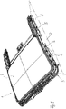
- a passenger car has a roof area D which, in Fig. 1 is indicated.
- This roof area D is provided with a roof opening in which a sliding roof system 1 is fitted.
- the sunroof system 1 has a support frame 3, which is provided at its longitudinal sides seen in the vehicle longitudinal direction, each with a guide rail profile 4.
- the respective guide rail profile 4 has a plurality over the length of the guide rail profile 4 distributed arranged Befest Trentsdome 5, via which the support frame 3 is firmly connected to the roof area D.
- fasteners in the form of screw, rivet, welded joints or adhesive joints are provided.
- the fastening dome 5 corresponding Mounting holes on the basis of Fig. 2 and 3 shown but not specified.
- the sunroof system 1 is provided with a movable roof part 2, which by means of a not shown control kinematics along the guide rail profiles 4 between a in Fig. 1 shown closed position, a fan position and an open position is displaced.
- the guide rail profile 4 on each side of the support frame 3 is made in each case as a metallic extruded profile of a light metal alloy, which is further processed by cold forming in addition.
- the guide rail profile 4 is machined by cutting to provide holes, recesses, slots and the like.
- the guide rail profile 4 has on a roof part 2 facing the longitudinal side of a guide portion F, which is designed as a hollow profile section to perform various functional parts of the control kinematics for the displacement of the roof part 2 can.
- To the guide portion F includes - in the vehicle transverse direction - to the outside a gutter section W, which is channel-shaped and has a bottom portion 7 and two side wall portions, of which a side wall portion 6 integrally merges into a mounting portion B which is parallel to the gutter section W on a to Guide section F opposite longitudinal side of the water gutter section W runs.
- the gutter section W and the attachment section B merge into one another in one piece.
- the guide rail profile 4 is designed as a one-piece component, in which the guide section F, the gutter section W and the attachment section B are integrally integrated.
- the guide section F is made as a separate extruded hollow profile and the gutter section W and the mounting section B are prepared as another sheet metal part separately to the guide section F and connected after completion over an entire length of the guide section F fixed to the guide section F.
- the guide rail profile 4 thus formed can therefore also be handled as a uniform and dimensionally stable component.
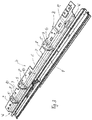
- the attachment portion B has three attachment domes 5 which are distributed over a length of the attachment portion B.
- the fastening domes 5 are each formed by a dome-shaped expression of the mounting portion B upwards.
- the expression is formed by a dome-shaped curvature 8 in the region of the top of the attachment portion B, which continues to the side wall portion 6 of the water gutter section W in a - viewed in plan view of the side wall portion 6 - trapezoidal Bulge 9, which continues by means of a lower transition region 10 in the bottom portion 7 of the water channel section W and there terminates in a flat bottom surface of the bottom portion 7.
- the bulge 9 tapers like a wedge towards the bottom region 7 of the water gutter section W.
- the expression is formed so that there is a dome-shaped curved transition between the bulge 8 and the bulge 9.
- the bulge 9 merges into the transition region 10 through a concave indentation.
- Details on the design of the expression in the region of the respective fastening dome 5 are the Fig. 3 good to take.
- a wall thickness of the guide rail profile 4 is kept at least substantially the same over the entire fastening section B and the gutter section W, including the regions of the embossments on the fastening domes 5.
- the shapes 8 to 10 in the region of the fastening dome 5 "flow" from an upper side of the fastening section 5 over the side wall region 6 to the bottom region 7 of the water channel section W.
- the respective expression extends on the one hand via an unspecified longitudinal edge region, which forms an upper edge region of the side wall region 6, and on the other via a lower longitudinal edge region of the water gutter section W, which forms a transition between the side wall region 6 and the bottom region 7 of the water gutter section W.
- the guide rail profile 4 in the region of the water channel section W has a further stiffening in the form of a bulge 11, which is arranged axially offset from the attachment domes 5 in the longitudinal direction and is integrally formed in the side wall region 6.
- the bulge 11 extends over almost an entire height of the side wall region 6 and continues over the lower longitudinal edge region into the bottom region 7 of the water gutter section W.
- the bulge 11 protrudes upwards over a surface of the side wall region 6 and towards the guide section F, with transition regions being curved concavely to planar surfaces of the side wall region 6 and the bottom region 7 to provide a continuous and continuous transition to the respective planar surface of the bottom region 7 and of the sidewall region 6.
Landscapes
- Engineering & Computer Science (AREA)
- Mechanical Engineering (AREA)
- Seal Device For Vehicle (AREA)
- Fittings On The Vehicle Exterior For Carrying Loads, And Devices For Holding Or Mounting Articles (AREA)
- Vehicle Interior And Exterior Ornaments, Soundproofing, And Insulation (AREA)
Abstract
Description
- Die Erfindung betrifft ein Schiebedachsystem eines Kraftfahrzeugs mit einem Führungsschienenprofil, das einen Befestigungsabschnitt mit mehreren Befestigungsdomen zur Verbindung des Führungsschienenprofils mit einem fahrzeugfesten Dachbereich sowie einen - in Längsrichtung des Führungsschienenprofils gesehen - parallel zu dem Befestigungsabschnitt verlaufenden Wasserrinnenabschnitt aufweist, an den - in Querrichtung des Führungsschienenprofils gesehen - ein Führungsabschnitt zur Führung einer Steuerkinematik für ein bewegliches Dachteil anschließt, wobei der Befestigungsabschnitt mit einstückig ausgeformten Versteifungen versehen ist.
- Die Erfindung betrifft zudem ein Führungsschienenprofil für ein derartiges Schiebedachsystem.
- Ein derartiges Schiebedachsystem ist aus der
DE 10 2009 025 122 B4 bekannt. Das bekannte Schiebedachsystem weist eine Führungsschiene auf, die mit einem Befestigungsabschnitt versehen ist, mittels dessen die Führungsschiene mit einem fahrzeugfesten Dachbereich des Kraftfahrzeugs verbunden werden kann. An den Führungsabschnitt schließt - in Fahrzeugquerrichtung gesehen - ein Wasserrinnenabschnitt an, zu dem ein Führungsabschnitt benachbart ist, der zur Führung einer Steuerkinematik für ein bewegliches Dachteil des Schiebedachsystems dient. In dem Befestigungsabschnitt ist mindestens eine Sicke angeordnet, um den Befestigungsabschnitt zu versteifen. - Aufgabe der Erfindung ist es, ein Schiebedachsystem und ein Führungsschienenprofil der eingangs genannten Art zu schaffen, die eine verbesserte Funktion gegenüber dem Stand der Technik ermöglichen.
- Diese Aufgabe wird für das Schiebedachsystem dadurch gelöst, dass die Versteifungen an den Befestigungsdomen ausgebildet sind und in Querrichtung des Führungsschienenprofils kontinuierlich fortgesetzt bis in den Wasserrinnenabschnitt hinein erstreckt sind. Dadurch wird eine erhöhte Steifigkeit des Führungsschienenprofils quer zur Längsrichtung des Führungsschienenprofils insbesondere auf Höhe der Befestigungsdome erreicht. Hierdurch ist eine erhöhte Stabilität einer Verbindung zwischen dem Schiebedachsystem und dem fahrzeugfesten Dachbereich des Kraftfahrzeugs erzielbar. Die erhöhte Steifigkeit führt zu besseren Führungs- und Laufeigenschaften für die Steuerkinematik, die das bewegliche Dachteil verlagert. Die erfindungsgemäße Lösung eignet sich in besonders vorteilhafter Weise für den Einsatz bei Personenkraftwagen. Ein erfindungsgemäßes Schiebedachsystem kann jedoch auch bei anderen Kraftfahrzeugen zu Wasser, zu Luft und zu Lande eingesetzt werden. Ein Einsatz des erfindungsgemäßen Schiebedachsystems ist in gleicher Weise bei gezogenen Fahrzeugen wie insbesondere Wohnanhängern oder Eisenbahnwaggons möglich.
- In Ausgestaltung der Erfindung ist als Versteifung wenigstens eine zusätzliche Auswölbung im Wasserrinnenabschnitt ausgebildet, die in Längsrichtung versetzt zu den Befestigungsdomen vorgesehen ist. Die zusätzliche Auswölbung ist ebenfalls einstückig im Führungsschienenprofil ausgebildet und versteift das Führungsschienenprofil weiter.
- In weiterer Ausgestaltung der Erfindung ist die Versteifung im Bereich wenigstens eines Befestigungsdoms als Ausprägung gestaltet, die kontinuierlich in einen Seitenwandbereich des Wasserrinnenabschnitts nach unten gezogen ist. Die Ausprägung stellt eine Kaltumformung des Führungsschienenprofils dar. Das Führungsschienenprofil ist vorzugsweise aus einer Leichtmetalllegierung hergestellt und insbesondere als Strangpressprofil gestaltet. Alternativ ist das Führungsschienenprofil aus einer ebenen Metallplatte durch Stanz-/Biegetechnik hergestellt. In letzterem Fall kann in einem Arbeitsgang mit der Stanz-/Biegetechnik auch bereits die wenigstens eine Ausprägung gebildet werden.
- In Ausgestaltung der Erfindung ist die Ausprägung von dem Befestigungsdom ausgehend über den Seitenwandbereich bis in einen Bodenbereich des Wasserrinnenabschnitts hinein erstreckt. Damit erstreckt die Ausprägung sich kontinuierlich vom Befestigungsdom über eine gesamte Höhe des Seitenwandbereichs bis in den Bodenbereich des Wasserrinnenabschnitts.
- In weiterer Ausgestaltung der Erfindung sind die wenigstens eine Auswölbung sowie die wenigstens eine Ausprägung relativ zu einer Oberseite des Führungsschienenprofils nach oben ausgeformt. Durch die Ausformung nach oben ist gewährleistet, dass im Wasserrinnenabschnitt keine Wasserreste verbleiben können. Bei Sicken gemäß dem Stand der Technik, die nach innen verlaufende Einwölbungen bilden, können Wasserreste in diesen Einwölbungen verbleiben, die zu Feuchtigkeits- oder Korrosionsproblemen führen können.
- In weiterer Ausgestaltung der Erfindung weist die wenigstens eine Ausprägung und/oder die wenigstens eine Auswölbung in Randbereichen mit größerer Querschnittskrümmung eine größere Materialstärke auf als in Übergangsbereichen mit geringerer Querschnittskrümmung. Diese Ausgestaltung ist durch einen Prägevorgang mit einem Prägestempel und einem von entgegengesetzter Richtung auf das Führungsschienenprofil wirkenden Gegenstempel realisierbar. Hierdurch wird die Steifigkeit des Führungsschienenprofils im Bereich der Ausprägung und/oder der Auswölbung weiter verbessert.
- In weiterer Ausgestaltung der Erfindung ist die Ausprägung über wenigstens einen Längskantenbereich des Führungsschienenprofils hinweg erstreckt. Hierdurch wird eine zusätzliche Versteifung des entsprechenden Längskantenbereichs des Führungsschienenprofils erzielt.
- In weiterer Ausgestaltung der Erfindung verjüngt die Ausprägung sich ausgehend von dem Befestigungsdom in Richtung des Bodenbereichs des Wasserrinnenabschnitts. Unter der Verjüngung ist eine kontinuierliche Verringerung der Breite der Ausprägung über den Verlauf der Ausprägung in Fahrzeughochrichtung zu verstehen. Die Ausprägung wird ausgehend von einem breiten Bereich auf Höhe des Befestigungsdoms über den Seitenwandbereich nach unten zum Bodenbereich hin kontinuierlich immer schmäler.
- Für das Führungsschienenprofil wird die der Erfindung zugrunde liegende Aufgabe dadurch gelöst, dass das Führungsschienenprofil Versteifungen aufweist, wie sie zuvor ausführlich beschrieben wurden.
- Weitere Vorteile und Merkmale der Erfindung ergeben sich aus den Ansprüchen sowie aus der nachfolgenden Beschreibung eines bevorzugten Ausführungsbeispiels der Erfindung, das anhand der Zeichnungen dargestellt ist.
- Fig. 1
- zeigt in perspektivischer Darstellung eine Ausführungsform eines erfindungsgemäßen Schiebedachsystems,
- Fig. 2
- in perspektivischer Darstellung eine Ausführungsform eines erfindungsgemäßen Führungsschienenprofils des Schiebedachsystems nach
Fig. 1 und - Fig. 3
- das Führungsschienenprofil nach
Fig. 2 in anderer perspektivischer Darstellung. - Ein Personenkraftwagen weist einen Dachbereich D auf, der in
Fig. 1 angedeutet ist. Dieser Dachbereich D ist mit einem Dachausschnitt versehen, in den ein Schiebedachsystem 1 eingepasst ist. Das Schiebedachsystem 1 weist einen Trägerrahmen 3 auf, der an seinen in Fahrzeuglängsrichtung gesehenen Längsseiten mit jeweils einem Führungsschienenprofil 4 versehen ist. Das jeweilige Führungsschienenprofil 4 weist mehrere über die Länge des Führungsschienenprofils 4 verteilt angeordnete Befestigungsdome 5 auf, über die der Trägerrahmen 3 mit dem Dachbereich D fest verbunden wird. Hierzu sind nicht dargestellte Befestigungsmittel in Form von Schraubverbindungen, Nietverbindungen, Schweißverbindungen oder Klebeverbindungen vorgesehen. Bei der Ausführungsform gemäß denFig. 1 bis 3 sind als Befestigungsmittel Schraubverbindungen vorgesehen. Hierzu weisen die Befestigungsdome 5 entsprechende Befestigungslöcher auf, die anhand derFig. 2 und3 gezeigt, jedoch nicht näher bezeichnet sind. - Das Schiebedachsystem 1 ist mit einem beweglichen Dachteil 2 versehen, das mittels einer nicht näher dargestellten Steuerkinematik entlang der Führungsschienenprofile 4 zwischen einer in
Fig. 1 dargestellten Schließstellung, einer Lüfterstellung sowie einer Offenstellung verlagerbar ist. - Das Führungsschienenprofil 4 auf jeder Seite des Trägerrahmens 3 ist jeweils als metallisches Strangpressprofil aus einer Leichtmetalllegierung hergestellt, das zusätzlich durch Kaltumformung weiter bearbeitet ist. Ergänzend ist das Führungsschienenprofil 4 durch Trennen bearbeitet, um Löcher, Aussparungen, Schlitze und Ähnliches vorzusehen. Das Führungsschienenprofil 4 weist auf einer dem Dachteil 2 zugewandten Längsseite einen Führungsabschnitt F auf, der als Hohlprofilabschnitt ausgeführt ist, um verschiedene Funktionsteile der Steuerkinematik zur Verlagerung des Dachteils 2 führen zu können. An den Führungsabschnitt F schließt - in Fahrzeugquerrichtung - nach außen ein Wasserrinnenabschnitt W an, der rinnenförmig gestaltet ist und einen Bodenbereich 7 sowie zwei Seitenwandbereiche aufweist, von denen ein Seitenwandbereich 6 einstückig in einen Befestigungsabschnitt B übergeht, der parallel zu dem Wasserrinnenabschnitt W auf einer zum Führungsabschnitt F gegenüberliegenden Längsseite des Wasserrinnenabschnitts W verläuft. Der Wasserrinnenabschnitt W und der Befestigungsabschnitt B gehen einstückig ineinander über. Das Führungsschienenprofil 4 ist als einteiliges Bauteil gestaltet, in dem der Führungsabschnitt F, der Wasserrinnenabschnitt W und der Befestigungsabschnitt B einstückig integriert sind. Bei einem nicht dargestellten Ausführungsbeispiel der Erfindung ist der Führungsabschnitt F als separates Strangpresshohlprofil hergestellt und der Wasserrinnenabschnitt W und der Befestigungsabschnitt B sind als weiteres Blechbiegeteil separat zum Führungsabschnitt F hergestellt und nach der Fertigstellung über eine gesamte Länge des Führungsabschnitts F fest mit dem Führungsabschnitt F verbunden. Nach einer Montage des Blechbauteils aus Wasserrinnenabschnitt W und Befestigungsabschnitt B an dem Führungsabschnitt F ist das so gebildete Führungsschienenprofil 4 demzufolge ebenso als einheitliches und formstabiles Bauteil handhabbar.
- Der Befestigungsabschnitt B weist drei Befestigungsdome 5 auf, die über eine Länge des Befestigungsabschnitts B verteilt angeordnet sind. Die Befestigungsdome 5 werden jeweils gebildet durch eine domförmige Ausprägung des Befestigungsabschnitts B nach oben. Die Ausprägung wird gebildet durch eine domartige Wölbung 8 im Bereich der Oberseite des Befestigungsabschnitts B, die sich zum Seitenwandbereich 6 des Wasserrinnenabschnitts W kontinuierlich fortsetzt in eine - in der Draufsicht auf den Seitenwandbereich 6 gesehen - trapezförmige Ausbuchtung 9, die mittels eines unteren Übergangsbereichs 10 sich in den Bodenbereich 7 des Wasserrinnenabschnitts W fortsetzt und dort in eine ebene Bodenfläche des Bodenbereichs 7 ausläuft. Die Ausbuchtung 9 verjüngt sich keilartig zum Bodenbereich 7 des Wasserrinnenabschnitts W hin. Die Ausprägung ist so gebildet, dass sich zwischen der Wölbung 8 und der Ausbuchtung 9 ein domförmig gewölbter und gekrümmter Übergang ergibt. Die Ausbuchtung 9 geht in den Übergangsbereich 10 über durch eine konkave Einwölbung. Details zur Gestaltung der Ausprägung im Bereich des jeweiligen Befestigungsdoms 5 sind der
Fig. 3 gut zu entnehmen. Eine Wandungsstärke des Führungsschienenprofils 4 ist über den gesamten Befestigungsabschnitt B und den Wasserrinnenabschnitt W einschließlich der Bereiche der Ausprägungen an den Befestigungsdomen 5 zumindest weitgehend gleich gehalten. Anhand derFig. 3 ist erkennbar, dass die Ausprägungen 8 bis 10 im Bereich der Befestigungsdome 5 wasserfallähnlich von einer Oberseite des Befestigungsabschnitts 5 ausgehend über den Seitenwandbereich 6 zum Bodenbereich 7 des Wasserrinnenabschnitts W "fließen". Dabei erstreckt sich die jeweilige Ausprägung zum einen über einen nicht näher bezeichneten Längskantenbereich, der einen oberen Randbereich des Seitenwandbereichs 6 bildet, und zum anderen über einen unteren Längskantenbereich des Wasserrinnenabschnitts W, der einen Übergang zwischen dem Seitenwandbereich 6 und dem Bodenbereich 7 des Wasserrinnenabschnitts W bildet. - Ergänzend weist das Führungsschienenprofil 4 im Bereich des Wasserrinnenabschnitts W noch eine weitere Versteifung in Form einer Auswölbung 11 auf, die in Längsrichtung axial versetzt zu den Befestigungsdomen 5 angeordnet ist und einstückig in dem Seitenwandbereich 6 ausgeformt ist. Die Auswölbung 11 erstreckt sich über nahezu eine gesamte Höhe des Seitenwandbereichs 6 und setzt sich über den unteren Längskantenbereich bis in den Bodenbereich 7 des Wasserrinnenabschnitts W fort. Die Auswölbung 11 ragt über eine Oberfläche des Seitenwandbereichs 6 höckerartig nach oben und zum Führungsabschnitt F hin ab, wobei Übergangsbereiche zu ebenen Flächen des Seitenwandbereichs 6 und des Bodenbereichs 7 konkavförmig gekrümmt sind, um einen stetigen und kontinuierlichen Übergang zur jeweils ebenen Oberfläche des Bodenbereichs 7 und des Seitenwandbereichs 6 zu erzielen.
Claims (9)
- Schiebedachsystem eines Kraftfahrzeugs mit einem Führungsschienenprofil (4), das einen Befestigungsabschnitt (B) mit mehreren Befestigungsdomen (5) zur Verbindung des Führungsschienenprofils (4) mit einem fahrzeugfesten Dachbereich (D) sowie einen - in Längsrichtung des Führungsschienenprofils (4) gesehen - parallel zu dem Befestigungsabschnitt (B) verlaufenden Wasserrinnenabschnitt (W) aufweist, an den - in Querrichtung des Führungsschienenprofils (4) gesehen - ein Führungsabschnitt (F) zur Führung einer Steuerkinematik für ein bewegliches Dachteil (2) anschließt, wobei der Befestigungsabschnitt (B) mit einstückig ausgeformten Versteifungen (8 bis 11) versehen ist, dadurch gekennzeichnet, dass die Versteifungen (8 bis 10) an den Befestigungsdomen (5) ausgebildet sind und in Querrichtung des Führungsschienenprofils (4) kontinuierlich fortgesetzt bis in den Wasserrinnenabschnitt (W) hinein erstreckt sind.
- Schiebedachsystem nach Anspruch 1, dadurch gekennzeichnet, das als Versteifung wenigstens eine zusätzliche Auswölbung (11) im Wasserrinnenabschnitt (W) ausgebildet ist, die in Längsrichtung versetzt zu den Befestigungsdomen (5) vorgesehen ist.
- Schiebedachsystem nach Anspruch 1 oder 2, dadurch gekennzeichnet, dass die Versteifung im Bereich wenigstens eines Befestigungsdoms (5) als Ausprägung (8 bis 10) gestaltet ist, die kontinuierlich in einen Seitenwandbereich (6) des Wasserrinnenabschnitts (W) nach unten gezogen ist.
- Schiebedachsystem nach Anspruch 3, dadurch gekennzeichnet, dass die Ausprägung (8 bis 10) von dem Befestigungsdom ausgehend über den Seitenwandbereich (6) bis in einen Bodenbereich (7) des Wasserrinnenabschnitts (W) hinein erstreckt ist.
- Schiebedachsystem nach einem der vorhergehenden Ansprüche, dadurch gekennzeichnet, dass die wenigstens eine Auswölbung (11) sowie die wenigstens eine Ausprägung (8 bis 10) relativ zu einer Oberseite des Führungsschienenprofils (4) nach oben ausgeformt sind.
- Schiebedachsystem nach Anspruch 5, dadurch gekennzeichnet, dass die wenigstens eine Ausprägung (8 bis 10) und/oder die wenigstens eine Auswölbung (11) in Randbereichen mit größerer Querschnittskrümmung eine größere Materialstärke aufweist als in Übergangsbereichen mit geringerer Querschnittskrümmung.
- Schiebedachsystem nach einem der vorhergehenden Ansprüche, dadurch gekennzeichnet, dass die Ausprägung (8 bis 10) über wenigstens einen Längskantenbereich des Führungsschienenprofils (4) hinweg erstreckt ist.
- Schiebedachsystem nach einem der vorhergehenden Ansprüche, dadurch gekennzeichnet, dass die Ausprägung (8 bis 10) sich ausgehend von dem Befestigungsdom (5) in Richtung des Bodenbereichs (7) des Wasserrinnenabschnitts (W) verjüngt.
- Führungsschienenprofil für ein Schiebedachsystem nach einem der vorhergehenden Ansprüche, wobei das Führungsschienenprofil (4) Versteifungen (8 bis 11) aufweist, die gemäß den kennzeichnenden Merkmalen von wenigstens einem der vorhergehenden Ansprüche gestaltet sind.
Applications Claiming Priority (1)
| Application Number | Priority Date | Filing Date | Title |
|---|---|---|---|
| DE102016213823.5A DE102016213823A1 (de) | 2016-07-27 | 2016-07-27 | Schiebedachsystem eines Kraftfahrzeugs und Führungsschienenprofil hierfür |
Publications (2)
| Publication Number | Publication Date |
|---|---|
| EP3275709A1 true EP3275709A1 (de) | 2018-01-31 |
| EP3275709B1 EP3275709B1 (de) | 2018-12-12 |
Family
ID=59269950
Family Applications (1)
| Application Number | Title | Priority Date | Filing Date |
|---|---|---|---|
| EP17179161.9A Active EP3275709B1 (de) | 2016-07-27 | 2017-06-30 | Führungsschienenprofil für ein schiebedachsystem eines kraftfahrzeugs und schiebedachsystem |
Country Status (4)
| Country | Link |
|---|---|
| US (1) | US10065485B2 (de) |
| EP (1) | EP3275709B1 (de) |
| CN (1) | CN107825947B (de) |
| DE (1) | DE102016213823A1 (de) |
Citations (2)
| Publication number | Priority date | Publication date | Assignee | Title |
|---|---|---|---|---|
| DE102009025122B4 (de) * | 2009-06-16 | 2011-06-09 | Webasto Ag | Führungsschiene für ein bewegliches Dachelement eines Fahrzeugdachs und Fahrzeugdach |
| DE102013020141A1 (de) * | 2013-12-06 | 2015-06-11 | Webasto SE | Führungsschiene für ein bewegliches Element eines Fahrzeugdachs |
Family Cites Families (12)
| Publication number | Priority date | Publication date | Assignee | Title |
|---|---|---|---|---|
| JP2002187429A (ja) * | 2000-12-20 | 2002-07-02 | Toyoda Gosei Co Ltd | 可動ルーフ用レール |
| DE10144738B4 (de) * | 2001-09-11 | 2005-08-11 | Arvinmeritor Gmbh | Rahmen für ein Fahrzeug-Schiebedach oder -Schiebehebedach |
| JP4465000B2 (ja) * | 2007-11-15 | 2010-05-19 | 八千代工業株式会社 | サンルーフ装置 |
| EP2353906B1 (de) * | 2010-01-26 | 2013-03-20 | Inalfa Roof Systems Group B.V. | Dachanordnung und Verfahren zur Montage eines Siebelements |
| JP5790221B2 (ja) * | 2011-07-12 | 2015-10-07 | アイシン精機株式会社 | 車両用ルーフ装置 |
| CN202463523U (zh) * | 2012-03-13 | 2012-10-03 | 马传贤 | 一种汽车天窗滑轨 |
| JP6001304B2 (ja) * | 2012-04-10 | 2016-10-05 | ベバスト ジャパン株式会社 | サンルーフ装置 |
| JP6001303B2 (ja) * | 2012-04-10 | 2016-10-05 | ベバスト ジャパン株式会社 | サンルーフ装置 |
| CN203681226U (zh) * | 2014-01-22 | 2014-07-02 | 嘉兴敏实机械有限公司 | 一种汽车车顶天窗导轨 |
| JP6330558B2 (ja) * | 2014-07-31 | 2018-05-30 | アイシン精機株式会社 | サンルーフ装置 |
| CN204712842U (zh) * | 2015-05-22 | 2015-10-21 | 宁波昌扬机械工业有限公司 | 冲压式车辆天窗导轨 |
| CN205044497U (zh) * | 2015-10-10 | 2016-02-24 | 北京汽车股份有限公司 | 汽车顶棚固定支架及汽车 |
-
2016
- 2016-07-27 DE DE102016213823.5A patent/DE102016213823A1/de not_active Ceased
-
2017
- 2017-06-30 EP EP17179161.9A patent/EP3275709B1/de active Active
- 2017-07-26 CN CN201710617422.7A patent/CN107825947B/zh active Active
- 2017-07-26 US US15/660,041 patent/US10065485B2/en active Active
Patent Citations (2)
| Publication number | Priority date | Publication date | Assignee | Title |
|---|---|---|---|---|
| DE102009025122B4 (de) * | 2009-06-16 | 2011-06-09 | Webasto Ag | Führungsschiene für ein bewegliches Dachelement eines Fahrzeugdachs und Fahrzeugdach |
| DE102013020141A1 (de) * | 2013-12-06 | 2015-06-11 | Webasto SE | Führungsschiene für ein bewegliches Element eines Fahrzeugdachs |
Also Published As
| Publication number | Publication date |
|---|---|
| CN107825947A (zh) | 2018-03-23 |
| US10065485B2 (en) | 2018-09-04 |
| DE102016213823A1 (de) | 2018-02-01 |
| CN107825947B (zh) | 2021-11-30 |
| EP3275709B1 (de) | 2018-12-12 |
| US20180029453A1 (en) | 2018-02-01 |
Similar Documents
| Publication | Publication Date | Title |
|---|---|---|
| DE10206768B4 (de) | Kotflügelanordnung für ein Kraftfahrzeug | |
| DE102005055705B4 (de) | Montageträger in Hybridstruktur | |
| DE102007036366A1 (de) | Fahrzeugdach mit einem Dachmodul | |
| EP2676046B1 (de) | STOßFÄNGER FÜR KRAFTFAHRZEUGE MIT INTEGRIERTERN FUßGÄNGERSCHUTZSYSTEM | |
| EP3245118B1 (de) | Hohlprofil mit sicken | |
| DE10126195C1 (de) | Fronthaubenanordnung für einen Personenkraftwagen | |
| DE2759029C2 (de) | ||
| DE4139303A1 (de) | Mittelsaeule an einer karosserie eines personenkraftwagens | |
| DE112014000458B4 (de) | Front-Karosseriestruktur eines Kraftfahrzeugs | |
| DE102012006533A1 (de) | Kraftfahrzeug mit Wasserkastenbaugruppe | |
| WO2017157821A1 (de) | Kraftfahrzeug | |
| DE19956430B4 (de) | Fahrzeugkarosserie | |
| EP1690780A2 (de) | Dachanordnung für Kraftfahrzeuge | |
| EP1300323A2 (de) | Grossflächiges Karrosserieelement eines Kraftfahrzeuges | |
| DE102009057833B4 (de) | Vorrichtung zur Halterung eines Funktionsteils, insbesondere eines Dachhaltegriffs, in einem Fahrzeug | |
| EP2332810A2 (de) | Karosserie eines Kraftfahrzeugs | |
| DE102010049983B4 (de) | Trägerprofil für einen Dachquerträger eines Kraftfahrzeugs | |
| DE102013003433A1 (de) | Haube für ein Kraftfahrzeug | |
| DE102005011834B4 (de) | Seitlicher Dachrahmen für ein Kraftfahrzeug | |
| EP3275709B1 (de) | Führungsschienenprofil für ein schiebedachsystem eines kraftfahrzeugs und schiebedachsystem | |
| DE102020202883A1 (de) | Unterbaustruktur für ein Fahrzeug | |
| DE102004043544B4 (de) | Spoiler | |
| DE102022120617B4 (de) | Stoßfängeranordnung mit endseitiger Verlängerung | |
| DE10116437B4 (de) | Karosserie eines Fahrzeuges | |
| DE102010054688A1 (de) | Bodenstruktur für ein Kraftfahrzeug, Fahrzeugkarosserie und Kraftfahrzeug |
Legal Events
| Date | Code | Title | Description |
|---|---|---|---|
| PUAI | Public reference made under article 153(3) epc to a published international application that has entered the european phase |
Free format text: ORIGINAL CODE: 0009012 |
|
| STAA | Information on the status of an ep patent application or granted ep patent |
Free format text: STATUS: THE APPLICATION HAS BEEN PUBLISHED |
|
| AK | Designated contracting states |
Kind code of ref document: A1 Designated state(s): AL AT BE BG CH CY CZ DE DK EE ES FI FR GB GR HR HU IE IS IT LI LT LU LV MC MK MT NL NO PL PT RO RS SE SI SK SM TR |
|
| AX | Request for extension of the european patent |
Extension state: BA ME |
|
| STAA | Information on the status of an ep patent application or granted ep patent |
Free format text: STATUS: REQUEST FOR EXAMINATION WAS MADE |
|
| 17P | Request for examination filed |
Effective date: 20180530 |
|
| RBV | Designated contracting states (corrected) |
Designated state(s): AL AT BE BG CH CY CZ DE DK EE ES FI FR GB GR HR HU IE IS IT LI LT LU LV MC MK MT NL NO PL PT RO RS SE SI SK SM TR |
|
| GRAP | Despatch of communication of intention to grant a patent |
Free format text: ORIGINAL CODE: EPIDOSNIGR1 |
|
| STAA | Information on the status of an ep patent application or granted ep patent |
Free format text: STATUS: GRANT OF PATENT IS INTENDED |
|
| INTG | Intention to grant announced |
Effective date: 20180727 |
|
| GRAS | Grant fee paid |
Free format text: ORIGINAL CODE: EPIDOSNIGR3 |
|
| GRAA | (expected) grant |
Free format text: ORIGINAL CODE: 0009210 |
|
| STAA | Information on the status of an ep patent application or granted ep patent |
Free format text: STATUS: THE PATENT HAS BEEN GRANTED |
|
| AK | Designated contracting states |
Kind code of ref document: B1 Designated state(s): AL AT BE BG CH CY CZ DE DK EE ES FI FR GB GR HR HU IE IS IT LI LT LU LV MC MK MT NL NO PL PT RO RS SE SI SK SM TR |
|
| REG | Reference to a national code |
Ref country code: GB Ref legal event code: FG4D Free format text: NOT ENGLISH |
|
| REG | Reference to a national code |
Ref country code: CH Ref legal event code: EP |
|
| REG | Reference to a national code |
Ref country code: AT Ref legal event code: REF Ref document number: 1075467 Country of ref document: AT Kind code of ref document: T Effective date: 20181215 |
|
| REG | Reference to a national code |
Ref country code: DE Ref legal event code: R096 Ref document number: 502017000490 Country of ref document: DE |
|
| REG | Reference to a national code |
Ref country code: IE Ref legal event code: FG4D Free format text: LANGUAGE OF EP DOCUMENT: GERMAN |
|
| REG | Reference to a national code |
Ref country code: NL Ref legal event code: MP Effective date: 20181212 |
|
| REG | Reference to a national code |
Ref country code: LT Ref legal event code: MG4D |
|
| PG25 | Lapsed in a contracting state [announced via postgrant information from national office to epo] |
Ref country code: FI Free format text: LAPSE BECAUSE OF FAILURE TO SUBMIT A TRANSLATION OF THE DESCRIPTION OR TO PAY THE FEE WITHIN THE PRESCRIBED TIME-LIMIT Effective date: 20181212 Ref country code: LV Free format text: LAPSE BECAUSE OF FAILURE TO SUBMIT A TRANSLATION OF THE DESCRIPTION OR TO PAY THE FEE WITHIN THE PRESCRIBED TIME-LIMIT Effective date: 20181212 Ref country code: HR Free format text: LAPSE BECAUSE OF FAILURE TO SUBMIT A TRANSLATION OF THE DESCRIPTION OR TO PAY THE FEE WITHIN THE PRESCRIBED TIME-LIMIT Effective date: 20181212 Ref country code: BG Free format text: LAPSE BECAUSE OF FAILURE TO SUBMIT A TRANSLATION OF THE DESCRIPTION OR TO PAY THE FEE WITHIN THE PRESCRIBED TIME-LIMIT Effective date: 20190312 Ref country code: NO Free format text: LAPSE BECAUSE OF FAILURE TO SUBMIT A TRANSLATION OF THE DESCRIPTION OR TO PAY THE FEE WITHIN THE PRESCRIBED TIME-LIMIT Effective date: 20190312 Ref country code: LT Free format text: LAPSE BECAUSE OF FAILURE TO SUBMIT A TRANSLATION OF THE DESCRIPTION OR TO PAY THE FEE WITHIN THE PRESCRIBED TIME-LIMIT Effective date: 20181212 Ref country code: ES Free format text: LAPSE BECAUSE OF FAILURE TO SUBMIT A TRANSLATION OF THE DESCRIPTION OR TO PAY THE FEE WITHIN THE PRESCRIBED TIME-LIMIT Effective date: 20181212 |
|
| PG25 | Lapsed in a contracting state [announced via postgrant information from national office to epo] |
Ref country code: GR Free format text: LAPSE BECAUSE OF FAILURE TO SUBMIT A TRANSLATION OF THE DESCRIPTION OR TO PAY THE FEE WITHIN THE PRESCRIBED TIME-LIMIT Effective date: 20190313 Ref country code: RS Free format text: LAPSE BECAUSE OF FAILURE TO SUBMIT A TRANSLATION OF THE DESCRIPTION OR TO PAY THE FEE WITHIN THE PRESCRIBED TIME-LIMIT Effective date: 20181212 Ref country code: SE Free format text: LAPSE BECAUSE OF FAILURE TO SUBMIT A TRANSLATION OF THE DESCRIPTION OR TO PAY THE FEE WITHIN THE PRESCRIBED TIME-LIMIT Effective date: 20181212 Ref country code: AL Free format text: LAPSE BECAUSE OF FAILURE TO SUBMIT A TRANSLATION OF THE DESCRIPTION OR TO PAY THE FEE WITHIN THE PRESCRIBED TIME-LIMIT Effective date: 20181212 |
|
| PG25 | Lapsed in a contracting state [announced via postgrant information from national office to epo] |
Ref country code: NL Free format text: LAPSE BECAUSE OF FAILURE TO SUBMIT A TRANSLATION OF THE DESCRIPTION OR TO PAY THE FEE WITHIN THE PRESCRIBED TIME-LIMIT Effective date: 20181212 |
|
| PG25 | Lapsed in a contracting state [announced via postgrant information from national office to epo] |
Ref country code: IT Free format text: LAPSE BECAUSE OF FAILURE TO SUBMIT A TRANSLATION OF THE DESCRIPTION OR TO PAY THE FEE WITHIN THE PRESCRIBED TIME-LIMIT Effective date: 20181212 Ref country code: CZ Free format text: LAPSE BECAUSE OF FAILURE TO SUBMIT A TRANSLATION OF THE DESCRIPTION OR TO PAY THE FEE WITHIN THE PRESCRIBED TIME-LIMIT Effective date: 20181212 Ref country code: PT Free format text: LAPSE BECAUSE OF FAILURE TO SUBMIT A TRANSLATION OF THE DESCRIPTION OR TO PAY THE FEE WITHIN THE PRESCRIBED TIME-LIMIT Effective date: 20190412 Ref country code: PL Free format text: LAPSE BECAUSE OF FAILURE TO SUBMIT A TRANSLATION OF THE DESCRIPTION OR TO PAY THE FEE WITHIN THE PRESCRIBED TIME-LIMIT Effective date: 20181212 |
|
| PG25 | Lapsed in a contracting state [announced via postgrant information from national office to epo] |
Ref country code: SM Free format text: LAPSE BECAUSE OF FAILURE TO SUBMIT A TRANSLATION OF THE DESCRIPTION OR TO PAY THE FEE WITHIN THE PRESCRIBED TIME-LIMIT Effective date: 20181212 Ref country code: EE Free format text: LAPSE BECAUSE OF FAILURE TO SUBMIT A TRANSLATION OF THE DESCRIPTION OR TO PAY THE FEE WITHIN THE PRESCRIBED TIME-LIMIT Effective date: 20181212 Ref country code: SK Free format text: LAPSE BECAUSE OF FAILURE TO SUBMIT A TRANSLATION OF THE DESCRIPTION OR TO PAY THE FEE WITHIN THE PRESCRIBED TIME-LIMIT Effective date: 20181212 Ref country code: IS Free format text: LAPSE BECAUSE OF FAILURE TO SUBMIT A TRANSLATION OF THE DESCRIPTION OR TO PAY THE FEE WITHIN THE PRESCRIBED TIME-LIMIT Effective date: 20190412 Ref country code: RO Free format text: LAPSE BECAUSE OF FAILURE TO SUBMIT A TRANSLATION OF THE DESCRIPTION OR TO PAY THE FEE WITHIN THE PRESCRIBED TIME-LIMIT Effective date: 20181212 |
|
| PGFP | Annual fee paid to national office [announced via postgrant information from national office to epo] |
Ref country code: FR Payment date: 20190626 Year of fee payment: 3 |
|
| REG | Reference to a national code |
Ref country code: DE Ref legal event code: R097 Ref document number: 502017000490 Country of ref document: DE |
|
| PLBE | No opposition filed within time limit |
Free format text: ORIGINAL CODE: 0009261 |
|
| STAA | Information on the status of an ep patent application or granted ep patent |
Free format text: STATUS: NO OPPOSITION FILED WITHIN TIME LIMIT |
|
| PG25 | Lapsed in a contracting state [announced via postgrant information from national office to epo] |
Ref country code: DK Free format text: LAPSE BECAUSE OF FAILURE TO SUBMIT A TRANSLATION OF THE DESCRIPTION OR TO PAY THE FEE WITHIN THE PRESCRIBED TIME-LIMIT Effective date: 20181212 |
|
| 26N | No opposition filed |
Effective date: 20190913 |
|
| PG25 | Lapsed in a contracting state [announced via postgrant information from national office to epo] |
Ref country code: MC Free format text: LAPSE BECAUSE OF FAILURE TO SUBMIT A TRANSLATION OF THE DESCRIPTION OR TO PAY THE FEE WITHIN THE PRESCRIBED TIME-LIMIT Effective date: 20181212 |
|
| REG | Reference to a national code |
Ref country code: BE Ref legal event code: MM Effective date: 20190630 |
|
| PG25 | Lapsed in a contracting state [announced via postgrant information from national office to epo] |
Ref country code: TR Free format text: LAPSE BECAUSE OF FAILURE TO SUBMIT A TRANSLATION OF THE DESCRIPTION OR TO PAY THE FEE WITHIN THE PRESCRIBED TIME-LIMIT Effective date: 20181212 |
|
| PG25 | Lapsed in a contracting state [announced via postgrant information from national office to epo] |
Ref country code: IE Free format text: LAPSE BECAUSE OF NON-PAYMENT OF DUE FEES Effective date: 20190630 |
|
| PG25 | Lapsed in a contracting state [announced via postgrant information from national office to epo] |
Ref country code: LU Free format text: LAPSE BECAUSE OF NON-PAYMENT OF DUE FEES Effective date: 20190630 Ref country code: BE Free format text: LAPSE BECAUSE OF NON-PAYMENT OF DUE FEES Effective date: 20190630 |
|
| REG | Reference to a national code |
Ref country code: CH Ref legal event code: PL |
|
| PG25 | Lapsed in a contracting state [announced via postgrant information from national office to epo] |
Ref country code: FR Free format text: LAPSE BECAUSE OF NON-PAYMENT OF DUE FEES Effective date: 20200630 Ref country code: LI Free format text: LAPSE BECAUSE OF NON-PAYMENT OF DUE FEES Effective date: 20200630 Ref country code: CH Free format text: LAPSE BECAUSE OF NON-PAYMENT OF DUE FEES Effective date: 20200630 |
|
| PG25 | Lapsed in a contracting state [announced via postgrant information from national office to epo] |
Ref country code: CY Free format text: LAPSE BECAUSE OF FAILURE TO SUBMIT A TRANSLATION OF THE DESCRIPTION OR TO PAY THE FEE WITHIN THE PRESCRIBED TIME-LIMIT Effective date: 20181212 |
|
| PG25 | Lapsed in a contracting state [announced via postgrant information from national office to epo] |
Ref country code: HU Free format text: LAPSE BECAUSE OF FAILURE TO SUBMIT A TRANSLATION OF THE DESCRIPTION OR TO PAY THE FEE WITHIN THE PRESCRIBED TIME-LIMIT; INVALID AB INITIO Effective date: 20170630 Ref country code: MT Free format text: LAPSE BECAUSE OF FAILURE TO SUBMIT A TRANSLATION OF THE DESCRIPTION OR TO PAY THE FEE WITHIN THE PRESCRIBED TIME-LIMIT Effective date: 20181212 |
|
| PG25 | Lapsed in a contracting state [announced via postgrant information from national office to epo] |
Ref country code: SI Free format text: LAPSE BECAUSE OF FAILURE TO SUBMIT A TRANSLATION OF THE DESCRIPTION OR TO PAY THE FEE WITHIN THE PRESCRIBED TIME-LIMIT Effective date: 20181212 |
|
| GBPC | Gb: european patent ceased through non-payment of renewal fee |
Effective date: 20210630 |
|
| PG25 | Lapsed in a contracting state [announced via postgrant information from national office to epo] |
Ref country code: GB Free format text: LAPSE BECAUSE OF NON-PAYMENT OF DUE FEES Effective date: 20210630 |
|
| PG25 | Lapsed in a contracting state [announced via postgrant information from national office to epo] |
Ref country code: MK Free format text: LAPSE BECAUSE OF FAILURE TO SUBMIT A TRANSLATION OF THE DESCRIPTION OR TO PAY THE FEE WITHIN THE PRESCRIBED TIME-LIMIT Effective date: 20181212 |
|
| REG | Reference to a national code |
Ref country code: AT Ref legal event code: MM01 Ref document number: 1075467 Country of ref document: AT Kind code of ref document: T Effective date: 20220630 |
|
| PG25 | Lapsed in a contracting state [announced via postgrant information from national office to epo] |
Ref country code: AT Free format text: LAPSE BECAUSE OF NON-PAYMENT OF DUE FEES Effective date: 20220630 |
|
| PGFP | Annual fee paid to national office [announced via postgrant information from national office to epo] |
Ref country code: DE Payment date: 20250624 Year of fee payment: 9 |