EP3275578A1 - Spann-löseeinheit - Google Patents
Spann-löseeinheit Download PDFInfo
- Publication number
- EP3275578A1 EP3275578A1 EP17162011.5A EP17162011A EP3275578A1 EP 3275578 A1 EP3275578 A1 EP 3275578A1 EP 17162011 A EP17162011 A EP 17162011A EP 3275578 A1 EP3275578 A1 EP 3275578A1
- Authority
- EP
- European Patent Office
- Prior art keywords
- repulsive
- release unit
- rod
- piston
- elements
- Prior art date
- Legal status (The legal status is an assumption and is not a legal conclusion. Google has not performed a legal analysis and makes no representation as to the accuracy of the status listed.)
- Granted
Links
- 239000012530 fluid Substances 0.000 claims 1
- 230000000694 effects Effects 0.000 description 2
- 230000007935 neutral effect Effects 0.000 description 2
- 230000000712 assembly Effects 0.000 description 1
- 238000000429 assembly Methods 0.000 description 1
- 230000005540 biological transmission Effects 0.000 description 1
- 230000003993 interaction Effects 0.000 description 1
- 238000003754 machining Methods 0.000 description 1
- 238000004519 manufacturing process Methods 0.000 description 1
Images

Classifications
-
- B—PERFORMING OPERATIONS; TRANSPORTING
- B23—MACHINE TOOLS; METAL-WORKING NOT OTHERWISE PROVIDED FOR
- B23B—TURNING; BORING
- B23B31/00—Chucks; Expansion mandrels; Adaptations thereof for remote control
- B23B31/02—Chucks
- B23B31/24—Chucks characterised by features relating primarily to remote control of the gripping means
- B23B31/26—Chucks characterised by features relating primarily to remote control of the gripping means using mechanical transmission through the working-spindle
- B23B31/261—Chucks characterised by features relating primarily to remote control of the gripping means using mechanical transmission through the working-spindle clamping the end of the toolholder shank
-
- B—PERFORMING OPERATIONS; TRANSPORTING
- B23—MACHINE TOOLS; METAL-WORKING NOT OTHERWISE PROVIDED FOR
- B23B—TURNING; BORING
- B23B31/00—Chucks; Expansion mandrels; Adaptations thereof for remote control
- B23B31/02—Chucks
- B23B31/24—Chucks characterised by features relating primarily to remote control of the gripping means
- B23B31/28—Chucks characterised by features relating primarily to remote control of the gripping means using electric or magnetic means in the chuck
-
- B—PERFORMING OPERATIONS; TRANSPORTING
- B23—MACHINE TOOLS; METAL-WORKING NOT OTHERWISE PROVIDED FOR
- B23B—TURNING; BORING
- B23B31/00—Chucks; Expansion mandrels; Adaptations thereof for remote control
- B23B31/02—Chucks
- B23B31/24—Chucks characterised by features relating primarily to remote control of the gripping means
- B23B31/30—Chucks characterised by features relating primarily to remote control of the gripping means using fluid-pressure means in the chuck
- B23B31/302—Hydraulic equipment, e.g. pistons, valves, rotary joints
-
- B—PERFORMING OPERATIONS; TRANSPORTING
- B23—MACHINE TOOLS; METAL-WORKING NOT OTHERWISE PROVIDED FOR
- B23Q—DETAILS, COMPONENTS, OR ACCESSORIES FOR MACHINE TOOLS, e.g. ARRANGEMENTS FOR COPYING OR CONTROLLING; MACHINE TOOLS IN GENERAL CHARACTERISED BY THE CONSTRUCTION OF PARTICULAR DETAILS OR COMPONENTS; COMBINATIONS OR ASSOCIATIONS OF METAL-WORKING MACHINES, NOT DIRECTED TO A PARTICULAR RESULT
- B23Q3/00—Devices holding, supporting, or positioning work or tools, of a kind normally removable from the machine
- B23Q3/15—Devices for holding work using magnetic or electric force acting directly on the work
-
- B—PERFORMING OPERATIONS; TRANSPORTING
- B23—MACHINE TOOLS; METAL-WORKING NOT OTHERWISE PROVIDED FOR
- B23B—TURNING; BORING
- B23B2231/00—Details of chucks, toolholder shanks or tool shanks
-
- B—PERFORMING OPERATIONS; TRANSPORTING
- B23—MACHINE TOOLS; METAL-WORKING NOT OTHERWISE PROVIDED FOR
- B23B—TURNING; BORING
- B23B2231/00—Details of chucks, toolholder shanks or tool shanks
- B23B2231/50—Devices to counteract clamping forces exerted within the spindle in order to release the tool or workpiece
-
- B—PERFORMING OPERATIONS; TRANSPORTING
- B23—MACHINE TOOLS; METAL-WORKING NOT OTHERWISE PROVIDED FOR
- B23B—TURNING; BORING
- B23B2260/00—Details of constructional elements
- B23B2260/10—Magnets
Definitions
- the invention relates to a clamping-release unit with a base body in which a pressure-actuated piston is arranged in a cylinder chamber for acting on a rod piston adjustable.
- This tension release unit according to the invention is characterized in that its complexity compared to a conventional release unit is hardly increased and the adjustment of the rod can be done in the operating states of clamping and releasing solely by the piston.
- the rod occupies a central position in which this has no contact with the wall of the stationary, non-rotating components by the interaction of the repulsive elements.
- the enclosure of the first Repulsivelementes by two pairwise arranged second Repulsivelemente a repulsion in both directions of adjustment of the rod, so as to the center position with To ensure a uniform distance from the wall of the second repulsive elements bearing component.
- first repulsive element is formed by a magnet
- second repulsive elements are formed by two magnets and that the arrangement of the second repulsive elements with respect to the first repulsive element is such that poles of the same name face each other. It is particularly expedient if the first repulsive element and / or the second repulsive elements are formed by permanent magnets.
- the desired repulsive effect between the first repulsive element and the second repulsive elements can be permanently achieved and utilized in a simple manner, that magnets always exist with the north and south poles, so that the second repulsive element with its north pole to the north pole of the first repulsive element can and the south pole of the first Repulsivelements the south pole of the other second repulsive element can be opposite.
- the magnets are annular. Since the rod is intended to rotate relative to the base body and the piston and thus the opposite of the first repulsive element and the pair of second repulsive elements is ensured regardless of the rotational position of the rod relative to the piston or the body.
- first repulsive element and the associated pair of second repulsive elements are provided several times in a track-like arrangement distributed over the circumference. It is the Number is such that in each rotational position of the rod, the first repulsive elements of the action of the second repulsive elements is exposed.
- the first repulsive element instead of the use of magnets, it is also possible for the first repulsive element to be formed by an electrode having a first electrical charge and for the pair of second repulsive elements to be formed by two electrodes with the same charge relative to the first electrode.
- the desired repulsive effect can be achieved in the same reliable manner by the influence of electrostatic forces, wherein in particular the possibility exists to provide permanently charged the electrode associated with the rod, while the other electrodes are charged and discharged as required and in particular the height of the Charge also the size of the acting forces can be influenced.
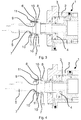
- a tension release unit 1 according to the invention shown, which has a base body 2, in which in a cylinder chamber 3 provided for acting on a rod 5 piston 4 pressure-medium-operated adjustable.
- the rod 5 is associated with a first repulsive element 6, which is arranged between a pair of second Repulsivelemente 7, which are associated with the piston 4 and an extension 8 of the piston 4.
- the first repulsive element 6 is placed on an annular collar 9 of the rod 5, so that two surfaces facing in the axial direction are provided, to which the second repulsive elements 7 can be arranged opposite one another.
- the first Repulsivelement 6 by a magnet namely a permanent magnet
- the second Repulsivelemente 7 are also formed by magnets, namely permanent magnets.
- the arrangement of the second repulsive elements 7 with respect to the first repulsive element 6 is such that poles of the same name face one another.
- the first repulsive element 6 points in the annular collar 9 of the rod 5 with its north pole 10 in the direction of the piston 4.
- the piston-side second repulsive element 7 is directed with its north pole 10 to the first repulsive element 6, while the second Repulsivelement 7, on the side facing away from the piston 4 of the annular collar 9 is directed with its south pole 11 to the south pole 11 of the first Repulsivelementes 6.
- the magnets are annular.
- the Fig. 3 shows the release position of the clamping release unit 1, in which the piston 4 is adjusted by the pressure means so that the power transmission takes place to overcome the self-locking by direct contact with the rod 5.
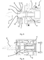
- Fig. 4 shows the clamping position in which to generate the self-locking of the clamping means also direct contact between the piston 4 and the rod 5 is. Both in the release position and in the clamping position, the repulsive force of the magnets is overcome by the pressure medium acting on the piston 4.
- Fig. 5 shows the neutral position in which the piston 4 is depressurized.
- the magnets cause a position of the rod 5, in which no contact with the wall stationary parts is given and so the rod 5 can be rotated.
Landscapes
- Engineering & Computer Science (AREA)
- Mechanical Engineering (AREA)
- Actuator (AREA)
- Jigs For Machine Tools (AREA)
- Gripping On Spindles (AREA)
Abstract
Description
- Die Erfindung betrifft eine Spann-Löseeinheit mit einem Grundkörper, in dem in einer Zylinderkammer ein zum Einwirken auf eine Stange vorgesehener Kolben druckmittelbetätigt verstellbar angeordnet ist.
- Aus der Praxis bekannt und beispielsweise in der
DE 10 2005 049 377 A1 beschrieben, sind Verriegelungssysteme als Verbindungsglied zwischen einem HSK-Spannsatz und der Betätigungsstange, bei der die herkömmlichen Federpakete überflüssig sind und eingespart werden können, weil die axiale Lage der Stange in der Spannstellung durch Selbsthemmung gesichert ist. Der damit verbundene Vorteil muss allerdings damit erkauft werden, dass keine konventionelle Löseeinheit eingesetzt werden kann, sondern eine Spann-Löseeinheit erforderlich ist, um beim Spannen die Stange in die Position zu verstellen, in der die Selbsthemmung gegeben ist, und im Übrigen unter Überwindung der Selbsthemmung die Verstellung der Stange in der dem Lösen entsprechenden Richtung wie bei einer konventionellen Löseeinheit möglich ist. Da der Grundkörper der Spann-Löseeinheit stationär ist, während die Stange sich mit dem HSK-Spannsatz mitdreht, muss für den Betrieb gewährleistet sein, dass die Stange sich gegenüber dem Grundkörper frei drehen kann. - Eine diese Anforderungen erfüllende, aus dem Stand der Technik bekannte Spann-Löseeinheit ist in der aus
Fig. 6 gezeigt, die als Doppelkolbenzylinder ausgeführt ist und für die Maschinensteuerung eine zusätzliche Steuerleitung benötigt wird, um den ordnungsgemäßen Betrieb zu gewährleisten. - Es ist Aufgabe der Erfindung, eine Spann-Löseeinheit der eingangs genannten Art so auszubilden, dass deren Aufbau vereinfacht und damit eine kostengünstigere Fertigung ermöglicht ist.
- Diese Aufgabe wird bei einer Spann-Löseeinheit der eingangs genannten Art dadurch gelöst, dass mindestens ein erstes Repulsivelement vorgesehen ist, das zwischen einem zugeordneten Paar zweiter Repulsivelemente angeordnet ist, und dass das mindestens erste Repulsivelement an einem Ringbund der Stange oder des Kolbens und das Paar zweiter Repulsivelemente an den anderen Teil von Kolben oder Stange ausgebildet sind.
- Diese erfindungsgemäße Spann-Löseeinheit zeichnet sich dadurch aus, dass deren Komplexität gegenüber einer konventionellen Löseeinheit kaum gesteigert ist und die Verstellung der Stange in die Betriebszustände des Spannens und Lösens allein durch den Kolben erfolgen kann. Für den Betriebszustand der Bearbeitung kann der Kolben drucklos geschaltet werden, wobei durch das Zusammenwirken der Repulsivelemente die Stange eine Mittelstellung einnimmt, in der diese keinen Kontakt zu der Wandung der stationären, nicht drehenden Bauteile hat. Zu beachten ist dabei, dass durch die Umfassung des ersten Repulsivelementes durch zwei paarweise angeordnete zweite Repulsivelemente eine Abstoßung in beide Verstellrichtungen der Stange erfolgt, um so die Mittelstellung mit gleichmäßigem Abstand von der Wandung des die zweiten Repulsivelemente tragenden Bauteils zu gewährleisten.
- Ganz besonders bevorzugt im Rahmen der Erfindung ist es, wenn das erste Repulsivelement durch einen Magneten gebildet ist, dass die zweiten Repulsivelemente durch zwei Magneten gebildet sind und dass die Anordnung der zweiten Repulsivelemente gegenüber dem ersten Repulsivelement so getroffen ist, dass gleichnamige Pole zueinander weisen. Ganz besonders zweckmäßig ist dabei, wenn das erste Repulsivelement und/oder die zweiten Repulsivelemente durch Permanentmagnete gebildet sind. Mit dieser Anordnung lässt sich in einfacher Weise dauerhaft die gewünschte abstoßende Wirkung zwischen dem ersten Repulsivelement und den zweiten Repulsivelementen erreichen und ausnutzen, dass Magnete stets mit Nord- und Südpol vorliegen, so dass das eine zweite Repulsivelement mit seinem Nordpol zu dem Nordpol des ersten Repulsivelements weisen kann und dem Südpol des ersten Repulsivelements der Südpol des anderen zweiten Repulsivelements gegenüberliegen kann.
- Vorteilhaft ist es weiterhin, wenn die Magnete ringförmig ausgebildet sind. Da die Stange bestimmungsgemäß sich gegenüber dem Grundkörper und dem Kolben verdrehen soll und so das Gegenüberliegen des ersten Repulsivelements und dem Paar zweiter Repulsivelemente unabhängig von der Drehlage der Stange gegenüber dem Kolben bzw. dem Grundkörper gewährleistet ist.
- Alternativ besteht auch die Möglichkeit, dass das erste Repulsivelement und das zugeordnete Paar zweiter Repulsivelemente mehrfach vorgesehen sind in einer gleismäßig über den Umfang verteilten Anordnung. Dabei ist die Anzahl so getroffen, dass in jeder Drehlage der Stange die ersten Repulsivelemente der Wirkung der zweiten Repulsivelemente ausgesetzt ist.
- Grundsätzlich besteht statt der Verwendung von Magneten auch die Möglichkeit, dass das erste Repulsivelement durch eine Elektrode mit einer ersten elektrischen Ladung gebildet ist und dass das Paar zweiter Repulsivelemente durch zwei Elektroden mit gleichnamiger Ladung gegenüber der ersten Elektrode gebildet ist. Mit dieser Ausführungsform kann in gleicher verlässlicher Weise die gewünschte Abstoßungswirkung durch den Einfluss elektrostatischer Kräfte erzielt werden, wobei insbesondere auch die Möglichkeit besteht, die der Stange zugeordnete Elektrode dauerhaft geladen bereitzustellen, während die anderen Elektroden bedarfsweise geladen und entladen werden und insbesondere über die Höhe der Ladung auch die Größe der wirkenden Kräfte beeinflusst werden kann.
- Im Folgenden wird die Erfindung an einem in der Zeichnung dargestellten Ausführungsbeispiel näher erläutert; es zeigen:
- Fig. 1
- eine Vorderansicht der erfindungsgemäßen Spann-Löseeinheit,
- Fig. 2
- eine aus dem Stand der Technik bekannte Löseeinheit, entsprechend dem Schnitt A-A aus
Fig. 1 - Fig. 3
- die erfindungsgemäße Spann-Löseeinheit gemäß dem Schnitt A-A aus
Fig. 1 in der Lösestellung, - Fig. 4
- die Spann-Löseeinheit aus
Fig. 3 in der Spannstellung, - Fig. 5
- die Spanneinheit aus
Fig. 3 in der Neutralstellung, und - Fig. 6
- einen Querschnitt durch eine aus dem Stand der Technik bekannte Spann-Löseeinheit, aufgebaut als Doppelkolbenzylinder.
- In der Zeichnung ist in den
Fig. 1 und3 bis 5 eine erfindungsgemäße Spann-Löseeinheit 1 gezeigt, die einen Grundkörper 2 aufweist, in dem in einer Zylinderkammer 3 ein zum Einwirken auf eine Stange 5 vorgesehener Kolben 4 druckmittelbetätigt verstellbar angeordnet ist. Bei dem in der Zeichnung dargestellten Ausführungsbeispiel ist der Stange 5 ein erstes Repulsivelement 6 zugeordnet, das zwischen einem Paar zweiter Repulsivelemente 7 angeordnet ist, die dem Kolben 4 bzw. einer Extension 8 des Kolbens 4 zugeordnet sind. Weiterhin ist erkennbar, dass das erste Repulsivelement 6 an einem Ringbund 9 der Stange 5 platziert ist, so dass zwei in axialer Richtung weisende Flächen bereitstehen, denen gegenüberliegend die zweiten Repulsivelemente 7 angeordnet werden können. - Bei dem in der Zeichnung dargestellten Ausführungsbeispiel sind das erste Repulsivelement 6 durch einen Magneten, nämlich einem Permanentmagneten, und die zweiten Repulsivelemente 7 gleichfalls durch Magnete, nämlich Permanentmagnete gebildet. Dabei ist die Anordnung der zweiten Repulsivelemente 7 gegenüber dem ersten Repulsivelement 6 so getroffen, dass gleichnamige Pole zueinander weisen. In der Zeichnung ist für das Ausführungsbeispiel ersichtlich, dass das erste Repulsivelement 6 in dem Ringbund 9 der Stange 5 mit seinem Nordpol 10 Richtung Kolben 4 weist. Dementsprechend ist das kolbenseitige zweite Repulsivelement 7 mit seinem Nordpol 10 zum ersten Repulsivelement 6 gerichtet, während das zweite Repulsivelement 7, auf der dem Kolben 4 abgewandten Seite des Ringbundes 9 mit seinem Südpol 11 zu dem Südpol 11 des ersten Repulsivelementes 6 gerichtet ist.
- Bei dem in der Zeichnung dargestellten Ausführungsbeispiel sind die Magnete ringförmig ausgebildet. Alternativ besteht allerdings auch die Möglichkeit, das erste Repulsivelement 6 und das zugeordnete Paar zweiter Repulsivelemente 7 mehrfach vorzusehen in einer gleichmäßig über den Umfang von Achse und Kolben 4 der Stange 5 verteilten Anordnung.
- Die
Fig. 3 zeigt dabei die Lösestellung der Spann-Löseeinheit 1, bei der durch das Druckmittel der Kolben 4 so verstellt ist, dass die Kraftübertragung zur Überwindung der Selbsthemmung durch unmittelbaren Kontakt mit der Stange 5 erfolgt. -
Fig. 4 zeigt die Spannstellung, bei der zur Generierung der Selbsthemmung der Spannmittel gleichfalls unmittelbarer Kontakt zwischen dem Kolben 4 und der Stange 5 besteht. Sowohl in der Lösestellung als auch in der Spannstellung wird die abstossende Kraft der Magnete durch das den Kolben 4 beaufschlagende Druckmittel überwunden. -
Fig. 5 zeigt die Neutralstellung, in der der Kolben 4 drucklos geschaltet ist. Die Magnete bewirken eine Stellung der Stange 5, bei der kein Kontakt zur Wandung stationärer Teile gegeben ist und so die Stange 5 verdreht werden kann. - Der Vergleich der erfindungsgemäßen Spann-Löseeinheit 1 aus
Fig. 3 mit der konventionellen Löseeinheit 12 ausFig. 2 zeigt, dass ein grundsätzlich gleicher Aufbau vorliegt und die Komplexität gegenüber der simplen Löseeinheit 12 nur geringfügig gesteigert ist, da dem Kolben 4 als Träger der zweiten Repulsivelemente 7 ein Adapterglied zugeordnet werden muss. Damit ergibt sich aber auch die Möglichkeit, dass vorbekannte Löseeinheiten 12 in einfacher Weise umgebaut und nachgerüstet werden können, so dass bei einem Wechsel zu einem Verriegelungssystem ohne Federpaket die existierende Löseeinheit 12 weiter genutzt und zur Spann-Löseeinheit 1 der erfindungsgemäßen Art umgebaut werden kann. -
- 1
- Spann-Löseeinheit
- 2
- Grundkörper
- 3
- Zylinderkammer
- 4
- Kolben
- 5
- Stange
- 6
- erstes Repulsivelement
- 7
- zweites Repulsivelement
- 8
- Extension
- 9
- Ringbund
- 10
- Nordpol
- 11
- Südpol
- 12
- Löseeinheit
Claims (6)
- Spann-Löseeinheit mit einem Grundkörper (2), in dem in einer Zylinderkammer (3) ein zum Einwirken auf eine Stange (5) vorgesehener Kolben (4) druckmittelbetätigt verstellbar angeordnet ist, dadurch gekennzeichnet, dass mindestens ein erstes Repulsivelement (6) vorgesehen ist, das zwischen einem zugeordneten Paar zweiter Repulsivelemente (7) angeordnet ist, und dass das mindestens erste Repulsivlelement (6) an einem Ringbund (9) der Stange (5) oder des Kolbens (4) und das Paar zweiter Repulsivelemente (7) an dem anderen Teil von Kolben (4) oder Stange (5) ausgebildet sind.
- Spann-Löseeinheit nach Anspruch 1, dadurch gekennzeichnet, dass das erste Repulsivelement (6) durch einen Magneten gebildet ist, dass die zweiten Repulsivelemente (7) durch zwei Magneten gebildet sind, und dass die Anordnung der zweiten Repulsivelemente (7) gegenüber dem ersten Repulsivelement (6) so getroffen ist, das gleichnamige Pole zueinander weisen.
- Spann-Löseeinheit nach Anspruch 2, dadurch gekennzeichnet, dass das erste Repulsivelement (6) und/oder die zweiten Repulsivelemente (7) durch Permantentmagnete gebildet sind.
- Spann-Löseeinheit nach Anspruch 2 oder 3, dadurch gekennzeichnet, dass die Magnete ringförmig ausgebildet sind.
- Spann-Löseinheit nach einem der Ansprüche 1 bis 3, dadurch gekennzeichnet, dass das erste Repulsivelement (6) und das zugeordnete Paar zweiter Repulsivelemente (7) mehrfach vorgesehen sind in einer gleichmäßig über den Umfang verteilten Anordnung.
- Spann-Löseeinheit nach Anspruch 1, dadurch gekennzeichnet, dass das erste Repulsivelement (6) durch eine Elektrode mit einer ersten elektrischen Ladung gebildet ist, und dass das Paar zweiter Repulsivelemente (7) durch zwei Elektroden mit gleichnamiger Ladung gegenüber der ersten Elektrode gebildet ist.
Applications Claiming Priority (1)
| Application Number | Priority Date | Filing Date | Title |
|---|---|---|---|
| DE102016113992.0A DE102016113992A1 (de) | 2016-07-28 | 2016-07-28 | Spann-Löseeinheit |
Publications (2)
| Publication Number | Publication Date |
|---|---|
| EP3275578A1 true EP3275578A1 (de) | 2018-01-31 |
| EP3275578B1 EP3275578B1 (de) | 2019-02-27 |
Family
ID=58412883
Family Applications (1)
| Application Number | Title | Priority Date | Filing Date |
|---|---|---|---|
| EP17162011.5A Not-in-force EP3275578B1 (de) | 2016-07-28 | 2017-03-21 | Spann-löseeinheit |
Country Status (4)
| Country | Link |
|---|---|
| EP (1) | EP3275578B1 (de) |
| JP (1) | JP2018015893A (de) |
| KR (1) | KR20180013691A (de) |
| DE (1) | DE102016113992A1 (de) |
Citations (2)
| Publication number | Priority date | Publication date | Assignee | Title |
|---|---|---|---|---|
| DE19840244A1 (de) * | 1998-09-03 | 2000-03-30 | Burgmann Dichtungswerk Feodor | Stoß- und Schwingungsdämpfer, insbesondere zur Aufhängung von Abgasanlagen von Kraftfahrzeugen |
| DE102005049377A1 (de) | 2005-09-13 | 2007-03-15 | Röhm Gmbh | Vorrichtung zum Spannen eines einen Hohlschaftkegel aufweisenden Werkstücks oder Werkzeugs |
-
2016
- 2016-07-28 DE DE102016113992.0A patent/DE102016113992A1/de not_active Withdrawn
-
2017
- 2017-03-21 EP EP17162011.5A patent/EP3275578B1/de not_active Not-in-force
- 2017-04-24 KR KR1020170052285A patent/KR20180013691A/ko not_active Withdrawn
- 2017-07-28 JP JP2017146194A patent/JP2018015893A/ja active Pending
Patent Citations (2)
| Publication number | Priority date | Publication date | Assignee | Title |
|---|---|---|---|---|
| DE19840244A1 (de) * | 1998-09-03 | 2000-03-30 | Burgmann Dichtungswerk Feodor | Stoß- und Schwingungsdämpfer, insbesondere zur Aufhängung von Abgasanlagen von Kraftfahrzeugen |
| DE102005049377A1 (de) | 2005-09-13 | 2007-03-15 | Röhm Gmbh | Vorrichtung zum Spannen eines einen Hohlschaftkegel aufweisenden Werkstücks oder Werkzeugs |
Also Published As
| Publication number | Publication date |
|---|---|
| EP3275578B1 (de) | 2019-02-27 |
| JP2018015893A (ja) | 2018-02-01 |
| DE102016113992A1 (de) | 2018-02-01 |
| KR20180013691A (ko) | 2018-02-07 |
Similar Documents
| Publication | Publication Date | Title |
|---|---|---|
| EP2150717B1 (de) | Magnetorheologische drehmomentübertragungsvorrichtung, deren verwendung sowie magnetorheologisches drehmomentübertragungsverfahren | |
| EP3794720A1 (de) | Magnetische stirndreh-kupplung zur übertragung von drehmomenten | |
| DE102013108027A1 (de) | Elektromagnetische Stellvorrichtung und System zur Verstellung einer Funktionalität eines Kraftfahrzeugaggregats | |
| DE102013100476B4 (de) | "Spannbuchse für hydraulische Spannelemente" | |
| WO2015154763A1 (de) | Vorrichtung zur höhenverstellung eines fahrzeugaufbaus | |
| DE102014200162A1 (de) | Maschine, insbesondere Verbrennungskraftmaschine, mit einem bewegbaren Bauteil, das mit einem schaltbaren Ventil ausgerüstet ist | |
| DE102012202267B4 (de) | Lageranordnung | |
| AT522792A4 (de) | Elektrische Kontaktanordnung | |
| DE102017119179A1 (de) | Drehdurchführung für eine Handhabungseinheit | |
| DE102009034297A1 (de) | Einstellbares Ventil mit Übergangsbereich | |
| EP2730686B1 (de) | Offenend-Spinnrotor | |
| EP0230626B1 (de) | Vorrichtung zur Verstellung der Federsteifigkeit einer Magnetfeder | |
| DE3402768C2 (de) | Bistabiles magnetisches Stellglied | |
| EP3275578B1 (de) | Spann-löseeinheit | |
| DE102018126391B4 (de) | Fahrzeugsitzelement für einen Fahrzeugsitz mit einer Restfederwegverstelleinrichtung | |
| DE102020109120B4 (de) | Elektromagnetische Stellvorrichtung und deren Verwendung | |
| WO2014194904A1 (de) | Aktive lagervorrichtung | |
| DE102011081893B3 (de) | Magnetischer Aktor und Verfahren zu dessen Betrieb | |
| DE202018106202U1 (de) | Schnellschaltender Magnet | |
| DE2143001A1 (de) | Bistabile axialfuehrung fuer stoessel und dergl | |
| DE102010019319B4 (de) | Permanentmagnetretarder | |
| EP3583615A1 (de) | Elektromagnetischer linearaktuator | |
| DE102010019318B4 (de) | Permanentmagnetretarder | |
| WO2016030411A1 (de) | Knickfedereinrichtung | |
| DE102022110634B4 (de) | Bremsvorrichtung |
Legal Events
| Date | Code | Title | Description |
|---|---|---|---|
| PUAI | Public reference made under article 153(3) epc to a published international application that has entered the european phase |
Free format text: ORIGINAL CODE: 0009012 |
|
| STAA | Information on the status of an ep patent application or granted ep patent |
Free format text: STATUS: THE APPLICATION HAS BEEN PUBLISHED |
|
| AK | Designated contracting states |
Kind code of ref document: A1 Designated state(s): AL AT BE BG CH CY CZ DE DK EE ES FI FR GB GR HR HU IE IS IT LI LT LU LV MC MK MT NL NO PL PT RO RS SE SI SK SM TR |
|
| AX | Request for extension of the european patent |
Extension state: BA ME |
|
| STAA | Information on the status of an ep patent application or granted ep patent |
Free format text: STATUS: REQUEST FOR EXAMINATION WAS MADE |
|
| 17P | Request for examination filed |
Effective date: 20180525 |
|
| RBV | Designated contracting states (corrected) |
Designated state(s): AL AT BE BG CH CY CZ DE DK EE ES FI FR GB GR HR HU IE IS IT LI LT LU LV MC MK MT NL NO PL PT RO RS SE SI SK SM TR |
|
| GRAP | Despatch of communication of intention to grant a patent |
Free format text: ORIGINAL CODE: EPIDOSNIGR1 |
|
| STAA | Information on the status of an ep patent application or granted ep patent |
Free format text: STATUS: GRANT OF PATENT IS INTENDED |
|
| INTG | Intention to grant announced |
Effective date: 20180926 |
|
| GRAS | Grant fee paid |
Free format text: ORIGINAL CODE: EPIDOSNIGR3 |
|
| GRAA | (expected) grant |
Free format text: ORIGINAL CODE: 0009210 |
|
| STAA | Information on the status of an ep patent application or granted ep patent |
Free format text: STATUS: THE PATENT HAS BEEN GRANTED |
|
| AK | Designated contracting states |
Kind code of ref document: B1 Designated state(s): AL AT BE BG CH CY CZ DE DK EE ES FI FR GB GR HR HU IE IS IT LI LT LU LV MC MK MT NL NO PL PT RO RS SE SI SK SM TR |
|
| REG | Reference to a national code |
Ref country code: GB Ref legal event code: FG4D Free format text: NOT ENGLISH |
|
| REG | Reference to a national code |
Ref country code: CH Ref legal event code: EP |
|
| REG | Reference to a national code |
Ref country code: AT Ref legal event code: REF Ref document number: 1100609 Country of ref document: AT Kind code of ref document: T Effective date: 20190315 |
|
| REG | Reference to a national code |
Ref country code: IE Ref legal event code: FG4D Free format text: LANGUAGE OF EP DOCUMENT: GERMAN |
|
| REG | Reference to a national code |
Ref country code: DE Ref legal event code: R096 Ref document number: 502017000805 Country of ref document: DE |
|
| REG | Reference to a national code |
Ref country code: NL Ref legal event code: MP Effective date: 20190227 |
|
| REG | Reference to a national code |
Ref country code: LT Ref legal event code: MG4D |
|
| PG25 | Lapsed in a contracting state [announced via postgrant information from national office to epo] |
Ref country code: SE Free format text: LAPSE BECAUSE OF FAILURE TO SUBMIT A TRANSLATION OF THE DESCRIPTION OR TO PAY THE FEE WITHIN THE PRESCRIBED TIME-LIMIT Effective date: 20190227 Ref country code: NL Free format text: LAPSE BECAUSE OF FAILURE TO SUBMIT A TRANSLATION OF THE DESCRIPTION OR TO PAY THE FEE WITHIN THE PRESCRIBED TIME-LIMIT Effective date: 20190227 Ref country code: LT Free format text: LAPSE BECAUSE OF FAILURE TO SUBMIT A TRANSLATION OF THE DESCRIPTION OR TO PAY THE FEE WITHIN THE PRESCRIBED TIME-LIMIT Effective date: 20190227 Ref country code: FI Free format text: LAPSE BECAUSE OF FAILURE TO SUBMIT A TRANSLATION OF THE DESCRIPTION OR TO PAY THE FEE WITHIN THE PRESCRIBED TIME-LIMIT Effective date: 20190227 Ref country code: PT Free format text: LAPSE BECAUSE OF FAILURE TO SUBMIT A TRANSLATION OF THE DESCRIPTION OR TO PAY THE FEE WITHIN THE PRESCRIBED TIME-LIMIT Effective date: 20190627 Ref country code: NO Free format text: LAPSE BECAUSE OF FAILURE TO SUBMIT A TRANSLATION OF THE DESCRIPTION OR TO PAY THE FEE WITHIN THE PRESCRIBED TIME-LIMIT Effective date: 20190527 |
|
| PG25 | Lapsed in a contracting state [announced via postgrant information from national office to epo] |
Ref country code: BG Free format text: LAPSE BECAUSE OF FAILURE TO SUBMIT A TRANSLATION OF THE DESCRIPTION OR TO PAY THE FEE WITHIN THE PRESCRIBED TIME-LIMIT Effective date: 20190527 Ref country code: GR Free format text: LAPSE BECAUSE OF FAILURE TO SUBMIT A TRANSLATION OF THE DESCRIPTION OR TO PAY THE FEE WITHIN THE PRESCRIBED TIME-LIMIT Effective date: 20190528 Ref country code: IS Free format text: LAPSE BECAUSE OF FAILURE TO SUBMIT A TRANSLATION OF THE DESCRIPTION OR TO PAY THE FEE WITHIN THE PRESCRIBED TIME-LIMIT Effective date: 20190627 Ref country code: LV Free format text: LAPSE BECAUSE OF FAILURE TO SUBMIT A TRANSLATION OF THE DESCRIPTION OR TO PAY THE FEE WITHIN THE PRESCRIBED TIME-LIMIT Effective date: 20190227 Ref country code: HR Free format text: LAPSE BECAUSE OF FAILURE TO SUBMIT A TRANSLATION OF THE DESCRIPTION OR TO PAY THE FEE WITHIN THE PRESCRIBED TIME-LIMIT Effective date: 20190227 Ref country code: RS Free format text: LAPSE BECAUSE OF FAILURE TO SUBMIT A TRANSLATION OF THE DESCRIPTION OR TO PAY THE FEE WITHIN THE PRESCRIBED TIME-LIMIT Effective date: 20190227 |
|
| REG | Reference to a national code |
Ref country code: DE Ref legal event code: R119 Ref document number: 502017000805 Country of ref document: DE |
|
| PG25 | Lapsed in a contracting state [announced via postgrant information from national office to epo] |
Ref country code: CZ Free format text: LAPSE BECAUSE OF FAILURE TO SUBMIT A TRANSLATION OF THE DESCRIPTION OR TO PAY THE FEE WITHIN THE PRESCRIBED TIME-LIMIT Effective date: 20190227 Ref country code: AL Free format text: LAPSE BECAUSE OF FAILURE TO SUBMIT A TRANSLATION OF THE DESCRIPTION OR TO PAY THE FEE WITHIN THE PRESCRIBED TIME-LIMIT Effective date: 20190227 Ref country code: RO Free format text: LAPSE BECAUSE OF FAILURE TO SUBMIT A TRANSLATION OF THE DESCRIPTION OR TO PAY THE FEE WITHIN THE PRESCRIBED TIME-LIMIT Effective date: 20190227 Ref country code: ES Free format text: LAPSE BECAUSE OF FAILURE TO SUBMIT A TRANSLATION OF THE DESCRIPTION OR TO PAY THE FEE WITHIN THE PRESCRIBED TIME-LIMIT Effective date: 20190227 Ref country code: EE Free format text: LAPSE BECAUSE OF FAILURE TO SUBMIT A TRANSLATION OF THE DESCRIPTION OR TO PAY THE FEE WITHIN THE PRESCRIBED TIME-LIMIT Effective date: 20190227 Ref country code: SK Free format text: LAPSE BECAUSE OF FAILURE TO SUBMIT A TRANSLATION OF THE DESCRIPTION OR TO PAY THE FEE WITHIN THE PRESCRIBED TIME-LIMIT Effective date: 20190227 Ref country code: IT Free format text: LAPSE BECAUSE OF FAILURE TO SUBMIT A TRANSLATION OF THE DESCRIPTION OR TO PAY THE FEE WITHIN THE PRESCRIBED TIME-LIMIT Effective date: 20190227 Ref country code: DK Free format text: LAPSE BECAUSE OF FAILURE TO SUBMIT A TRANSLATION OF THE DESCRIPTION OR TO PAY THE FEE WITHIN THE PRESCRIBED TIME-LIMIT Effective date: 20190227 |
|
| PG25 | Lapsed in a contracting state [announced via postgrant information from national office to epo] |
Ref country code: LU Free format text: LAPSE BECAUSE OF NON-PAYMENT OF DUE FEES Effective date: 20190321 Ref country code: PL Free format text: LAPSE BECAUSE OF FAILURE TO SUBMIT A TRANSLATION OF THE DESCRIPTION OR TO PAY THE FEE WITHIN THE PRESCRIBED TIME-LIMIT Effective date: 20190227 Ref country code: SM Free format text: LAPSE BECAUSE OF FAILURE TO SUBMIT A TRANSLATION OF THE DESCRIPTION OR TO PAY THE FEE WITHIN THE PRESCRIBED TIME-LIMIT Effective date: 20190227 |
|
| REG | Reference to a national code |
Ref country code: BE Ref legal event code: MM Effective date: 20190331 |
|
| PG25 | Lapsed in a contracting state [announced via postgrant information from national office to epo] |
Ref country code: MC Free format text: LAPSE BECAUSE OF FAILURE TO SUBMIT A TRANSLATION OF THE DESCRIPTION OR TO PAY THE FEE WITHIN THE PRESCRIBED TIME-LIMIT Effective date: 20190227 |
|
| PLBE | No opposition filed within time limit |
Free format text: ORIGINAL CODE: 0009261 |
|
| STAA | Information on the status of an ep patent application or granted ep patent |
Free format text: STATUS: NO OPPOSITION FILED WITHIN TIME LIMIT |
|
| PG25 | Lapsed in a contracting state [announced via postgrant information from national office to epo] |
Ref country code: IE Free format text: LAPSE BECAUSE OF NON-PAYMENT OF DUE FEES Effective date: 20190321 Ref country code: DE Free format text: LAPSE BECAUSE OF NON-PAYMENT OF DUE FEES Effective date: 20191001 |
|
| 26N | No opposition filed |
Effective date: 20191128 |
|
| PG25 | Lapsed in a contracting state [announced via postgrant information from national office to epo] |
Ref country code: SI Free format text: LAPSE BECAUSE OF FAILURE TO SUBMIT A TRANSLATION OF THE DESCRIPTION OR TO PAY THE FEE WITHIN THE PRESCRIBED TIME-LIMIT Effective date: 20190227 Ref country code: FR Free format text: LAPSE BECAUSE OF NON-PAYMENT OF DUE FEES Effective date: 20190427 Ref country code: BE Free format text: LAPSE BECAUSE OF NON-PAYMENT OF DUE FEES Effective date: 20190331 |
|
| PG25 | Lapsed in a contracting state [announced via postgrant information from national office to epo] |
Ref country code: TR Free format text: LAPSE BECAUSE OF FAILURE TO SUBMIT A TRANSLATION OF THE DESCRIPTION OR TO PAY THE FEE WITHIN THE PRESCRIBED TIME-LIMIT Effective date: 20190227 |
|
| PG25 | Lapsed in a contracting state [announced via postgrant information from national office to epo] |
Ref country code: MT Free format text: LAPSE BECAUSE OF FAILURE TO SUBMIT A TRANSLATION OF THE DESCRIPTION OR TO PAY THE FEE WITHIN THE PRESCRIBED TIME-LIMIT Effective date: 20190227 |
|
| REG | Reference to a national code |
Ref country code: CH Ref legal event code: PL |
|
| PG25 | Lapsed in a contracting state [announced via postgrant information from national office to epo] |
Ref country code: CH Free format text: LAPSE BECAUSE OF NON-PAYMENT OF DUE FEES Effective date: 20200331 Ref country code: LI Free format text: LAPSE BECAUSE OF NON-PAYMENT OF DUE FEES Effective date: 20200331 |
|
| PG25 | Lapsed in a contracting state [announced via postgrant information from national office to epo] |
Ref country code: CY Free format text: LAPSE BECAUSE OF FAILURE TO SUBMIT A TRANSLATION OF THE DESCRIPTION OR TO PAY THE FEE WITHIN THE PRESCRIBED TIME-LIMIT Effective date: 20190227 |
|
| PG25 | Lapsed in a contracting state [announced via postgrant information from national office to epo] |
Ref country code: HU Free format text: LAPSE BECAUSE OF FAILURE TO SUBMIT A TRANSLATION OF THE DESCRIPTION OR TO PAY THE FEE WITHIN THE PRESCRIBED TIME-LIMIT; INVALID AB INITIO Effective date: 20170321 |
|
| GBPC | Gb: european patent ceased through non-payment of renewal fee |
Effective date: 20210321 |
|
| PG25 | Lapsed in a contracting state [announced via postgrant information from national office to epo] |
Ref country code: GB Free format text: LAPSE BECAUSE OF NON-PAYMENT OF DUE FEES Effective date: 20210321 |
|
| PG25 | Lapsed in a contracting state [announced via postgrant information from national office to epo] |
Ref country code: MK Free format text: LAPSE BECAUSE OF FAILURE TO SUBMIT A TRANSLATION OF THE DESCRIPTION OR TO PAY THE FEE WITHIN THE PRESCRIBED TIME-LIMIT Effective date: 20190227 |
|
| REG | Reference to a national code |
Ref country code: AT Ref legal event code: MM01 Ref document number: 1100609 Country of ref document: AT Kind code of ref document: T Effective date: 20220321 |
|
| PG25 | Lapsed in a contracting state [announced via postgrant information from national office to epo] |
Ref country code: AT Free format text: LAPSE BECAUSE OF NON-PAYMENT OF DUE FEES Effective date: 20220321 |