EP3273381B1 - Dispositif rfid et procédé de communication avec au moins un transpondeur rfid - Google Patents
Dispositif rfid et procédé de communication avec au moins un transpondeur rfid Download PDFInfo
- Publication number
- EP3273381B1 EP3273381B1 EP17176998.7A EP17176998A EP3273381B1 EP 3273381 B1 EP3273381 B1 EP 3273381B1 EP 17176998 A EP17176998 A EP 17176998A EP 3273381 B1 EP3273381 B1 EP 3273381B1
- Authority
- EP
- European Patent Office
- Prior art keywords
- rfid
- transponder
- uii
- accordance
- inventory
- Prior art date
- Legal status (The legal status is an assumption and is not a legal conclusion. Google has not performed a legal analysis and makes no representation as to the accuracy of the status listed.)
- Active
Links
- 238000000034 method Methods 0.000 title claims description 29
- 238000004891 communication Methods 0.000 claims description 65
- 230000008569 process Effects 0.000 claims description 9
- 230000008859 change Effects 0.000 claims description 7
- 230000004044 response Effects 0.000 claims description 6
- 238000000926 separation method Methods 0.000 description 9
- 230000005540 biological transmission Effects 0.000 description 6
- 238000002955 isolation Methods 0.000 description 4
- 230000004807 localization Effects 0.000 description 4
- 238000005259 measurement Methods 0.000 description 4
- 230000008901 benefit Effects 0.000 description 3
- 238000012790 confirmation Methods 0.000 description 3
- 238000011156 evaluation Methods 0.000 description 2
- 239000000463 material Substances 0.000 description 2
- 238000013459 approach Methods 0.000 description 1
- 230000001010 compromised effect Effects 0.000 description 1
- 238000010276 construction Methods 0.000 description 1
- 238000007796 conventional method Methods 0.000 description 1
- 230000001419 dependent effect Effects 0.000 description 1
- 238000013461 design Methods 0.000 description 1
- 238000001514 detection method Methods 0.000 description 1
- 230000000694 effects Effects 0.000 description 1
- 230000005670 electromagnetic radiation Effects 0.000 description 1
- 238000004806 packaging method and process Methods 0.000 description 1
- 230000010287 polarization Effects 0.000 description 1
- 239000000047 product Substances 0.000 description 1
- 230000009467 reduction Effects 0.000 description 1
- 239000013589 supplement Substances 0.000 description 1
- 230000001629 suppression Effects 0.000 description 1
- 238000012360 testing method Methods 0.000 description 1
- 238000012800 visualization Methods 0.000 description 1
Images


Classifications
-
- H—ELECTRICITY
- H04—ELECTRIC COMMUNICATION TECHNIQUE
- H04B—TRANSMISSION
- H04B5/00—Near-field transmission systems, e.g. inductive or capacitive transmission systems
- H04B5/70—Near-field transmission systems, e.g. inductive or capacitive transmission systems specially adapted for specific purposes
- H04B5/77—Near-field transmission systems, e.g. inductive or capacitive transmission systems specially adapted for specific purposes for interrogation
-
- G—PHYSICS
- G06—COMPUTING; CALCULATING OR COUNTING
- G06K—GRAPHICAL DATA READING; PRESENTATION OF DATA; RECORD CARRIERS; HANDLING RECORD CARRIERS
- G06K7/00—Methods or arrangements for sensing record carriers, e.g. for reading patterns
- G06K7/10—Methods or arrangements for sensing record carriers, e.g. for reading patterns by electromagnetic radiation, e.g. optical sensing; by corpuscular radiation
- G06K7/10009—Methods or arrangements for sensing record carriers, e.g. for reading patterns by electromagnetic radiation, e.g. optical sensing; by corpuscular radiation sensing by radiation using wavelengths larger than 0.1 mm, e.g. radio-waves or microwaves
- G06K7/10366—Methods or arrangements for sensing record carriers, e.g. for reading patterns by electromagnetic radiation, e.g. optical sensing; by corpuscular radiation sensing by radiation using wavelengths larger than 0.1 mm, e.g. radio-waves or microwaves the interrogation device being adapted for miscellaneous applications
-
- G—PHYSICS
- G06—COMPUTING; CALCULATING OR COUNTING
- G06K—GRAPHICAL DATA READING; PRESENTATION OF DATA; RECORD CARRIERS; HANDLING RECORD CARRIERS
- G06K17/00—Methods or arrangements for effecting co-operative working between equipments covered by two or more of main groups G06K1/00 - G06K15/00, e.g. automatic card files incorporating conveying and reading operations
- G06K17/0022—Methods or arrangements for effecting co-operative working between equipments covered by two or more of main groups G06K1/00 - G06K15/00, e.g. automatic card files incorporating conveying and reading operations arrangements or provisious for transferring data to distant stations, e.g. from a sensing device
-
- G—PHYSICS
- G06—COMPUTING; CALCULATING OR COUNTING
- G06K—GRAPHICAL DATA READING; PRESENTATION OF DATA; RECORD CARRIERS; HANDLING RECORD CARRIERS
- G06K7/00—Methods or arrangements for sensing record carriers, e.g. for reading patterns
- G06K7/10—Methods or arrangements for sensing record carriers, e.g. for reading patterns by electromagnetic radiation, e.g. optical sensing; by corpuscular radiation
- G06K7/10009—Methods or arrangements for sensing record carriers, e.g. for reading patterns by electromagnetic radiation, e.g. optical sensing; by corpuscular radiation sensing by radiation using wavelengths larger than 0.1 mm, e.g. radio-waves or microwaves
- G06K7/10019—Methods or arrangements for sensing record carriers, e.g. for reading patterns by electromagnetic radiation, e.g. optical sensing; by corpuscular radiation sensing by radiation using wavelengths larger than 0.1 mm, e.g. radio-waves or microwaves resolving collision on the communication channels between simultaneously or concurrently interrogated record carriers.
- G06K7/10029—Methods or arrangements for sensing record carriers, e.g. for reading patterns by electromagnetic radiation, e.g. optical sensing; by corpuscular radiation sensing by radiation using wavelengths larger than 0.1 mm, e.g. radio-waves or microwaves resolving collision on the communication channels between simultaneously or concurrently interrogated record carriers. the collision being resolved in the time domain, e.g. using binary tree search or RFID responses allocated to a random time slot
-
- G—PHYSICS
- G06—COMPUTING; CALCULATING OR COUNTING
- G06K—GRAPHICAL DATA READING; PRESENTATION OF DATA; RECORD CARRIERS; HANDLING RECORD CARRIERS
- G06K7/00—Methods or arrangements for sensing record carriers, e.g. for reading patterns
- G06K7/10—Methods or arrangements for sensing record carriers, e.g. for reading patterns by electromagnetic radiation, e.g. optical sensing; by corpuscular radiation
- G06K7/10009—Methods or arrangements for sensing record carriers, e.g. for reading patterns by electromagnetic radiation, e.g. optical sensing; by corpuscular radiation sensing by radiation using wavelengths larger than 0.1 mm, e.g. radio-waves or microwaves
- G06K7/10118—Methods or arrangements for sensing record carriers, e.g. for reading patterns by electromagnetic radiation, e.g. optical sensing; by corpuscular radiation sensing by radiation using wavelengths larger than 0.1 mm, e.g. radio-waves or microwaves the sensing being preceded by at least one preliminary step
-
- G—PHYSICS
- G06—COMPUTING; CALCULATING OR COUNTING
- G06K—GRAPHICAL DATA READING; PRESENTATION OF DATA; RECORD CARRIERS; HANDLING RECORD CARRIERS
- G06K7/00—Methods or arrangements for sensing record carriers, e.g. for reading patterns
- G06K7/10—Methods or arrangements for sensing record carriers, e.g. for reading patterns by electromagnetic radiation, e.g. optical sensing; by corpuscular radiation
- G06K7/10009—Methods or arrangements for sensing record carriers, e.g. for reading patterns by electromagnetic radiation, e.g. optical sensing; by corpuscular radiation sensing by radiation using wavelengths larger than 0.1 mm, e.g. radio-waves or microwaves
- G06K7/10297—Methods or arrangements for sensing record carriers, e.g. for reading patterns by electromagnetic radiation, e.g. optical sensing; by corpuscular radiation sensing by radiation using wavelengths larger than 0.1 mm, e.g. radio-waves or microwaves arrangements for handling protocols designed for non-contact record carriers such as RFIDs NFCs, e.g. ISO/IEC 14443 and 18092
-
- H—ELECTRICITY
- H04—ELECTRIC COMMUNICATION TECHNIQUE
- H04B—TRANSMISSION
- H04B5/00—Near-field transmission systems, e.g. inductive or capacitive transmission systems
- H04B5/40—Near-field transmission systems, e.g. inductive or capacitive transmission systems characterised by components specially adapted for near-field transmission
- H04B5/48—Transceivers
Definitions
- the invention relates to an RFID device and a method for communicating with at least one RIFD transponder according to the preamble of claims 1 and 10, respectively.
- RFID systems are used to identify objects and goods and are used, among other things, to automate logistical movements. At an identification point, especially in the case of a change of the owner of the goods or a change of the means of transport, RFID transponders attached to the goods are read out and, if necessary, information is written back into the transponder. This leads to fast and traceable logistics movements. The collected information is used to control the forwarding, storage and sorting of goods and products.
- the RFID transponders are excited by electromagnetic radiation of the read-write system, also called interrogator, for emitting the stored information, wherein passive transponders obtain the necessary energy from the transmission energy of the reading system and the less usual active transponders have their own supply.
- passive transponders In the ultra-high frequency standard EPC Generation-2 UHF RFID, whose air interface is defined in ISO18000-6, is mainly considered and established, passive transponders are read out using the backscatter method.
- the anti-collision method defined in ISO18000-6 also enables separation of transponders of identical content.
- each transponder is addressed individually and independently of its contents in the so-called Inventory and asked to communicate.
- the duration of the inventory also called round, is divided into 2 Q-1 time slices or slots.
- Q is a parameter which the interrogator sets so that, given an expected or known number of transponders in the reading field, the probability of a random collision is small, without losing too much response time through empty slots.
- Each transponder in read range now generates a random number based on the parameter Q.
- the transponder responds only in the slot defined thereby and is silent otherwise, so as not to disturb the communication between the interrogator and other transponders.
- the transponder can communicate to the interrogator, inter alia, its unique identification parameter (UII, unique identification identifier).
- UAI unique identification parameter
- the interrogator After completing the inventory, the interrogator therefore knows all the transponders with which communication is possible. Since the transponders set their slots randomly independently, collisions are not excluded. The interrogator must recognize this and start a new inventory, possibly with another Q.
- the interrogator may also receive further access to the transponder as part of an inventory, i. submit and execute an Access command.
- a transponder with a certain UII is searched for.
- the command with this handle is sent to the transponder, executed there and confirmed.
- the known separation is therefore unsuitable.
- the transponders must be isolated geometrically-physically, so that is communicated by appropriate structures and specific choice of the transmission parameters of the interrogator with exactly the desired transponder. Some conceivable measures for this are the smallest possible distance between the interrogator and the transponder, a reduction of the transmission power to the smallest possible degree, constructive measures that shade other transponders or a suitable linear polarization.
- a SELECT mask can be set for the factory-set UII of the manufacturer, but only separates the entirety of the new transponder from possible further transponders. All this is complex and not possible in all situations. If the artificial separation fails, then all inadvertently receive the write command on the UII with addressed transponders and in the future will carry the identical new UIIs.
- an initial content is to be written on the transponder with the UII on the transponder, this content is given as a simple label or in an outer packaging of the transponder in the form of text, barcodes or 2D codes. Accordingly, the assignment between transponder and this information must be ensured at this precise time. Otherwise, not only will wrong UIIs be assigned, but other transponder data will be compromised.
- transponders have a manufacturer-programmed serial number in a different memory area than the UII. This would allow singulation using SELECT masks, and the initial UII could be assigned as well. This is a relatively time-consuming operation, especially since the serial numbers must first be read from the transponders. Transponders with preprogrammed serial numbers also tend to be the exception, with this approach offering at best a partial solution.
- the EP 2 490 150 A1 discloses an RFID reading tunnel for reading RFID transponders in a reading area. At least one additional receiving antenna is placed outside the reading area, with the help of which it is checked whether a read transponder is really in the reading range. Initially, the D1 also calls a direction determination based on signal strength or phase as a previously known way to ensure a correct assignment of information read from a transponder to an object in the reading area.
- reference transponders are arranged at a reference distance.
- the signal strength is compared with the reference signal strength of the reference transponder. If it is larger, it is assumed that the transponder is closer to the RFID reader than the reference transponder.
- the EP 2 562 676 A1 discloses a method and read / write device for an arrangement with a plurality of non-contact readable transponders.
- an additional indication with characteristics of the radio connection is also stored. From this, a quality measure of the detection is derived, based on which one of the transponders is selected.
- the invention therefore has the task of simplifying the separation.
- an RFID device and a method for communicating with at least one RIFD transponder according to claims 1 and 10, respectively.
- the RFID device is also referred to as an interrogator, RFID reader or RFID read-write device, because usually an RFID device is also capable of writing.
- a separating method is implemented in a control unit in order to be able to issue commands in each case only to one RFID transponder.
- Such commands are usually read or write commands to read data from the RFID transponder or store there, but there are also other commands that trigger, for example, a state change in the RFID transponder.
- the invention is based on the basic idea of linking the singulation method to a condition of the communication which is detected in a communication parameter.
- the communication parameter is therefore also independent of data stored on the RFID transponder.
- the examination of the communication parameter is preferably not intended as a substitute, but rather as a supplement to known singulation methods.
- the use of the term communication parameter in the singular is only a linguistic simplification and includes a combined evaluation of several communication parameters.
- the invention has the advantage that further criteria are created to decide which RFID transponder receives a command. This is possible without the initial effort described in initializing the UII. The separation is thereby suitably extended and covers situations that could previously lead to ambiguities.
- the communication parameter is preferably a level of the RFID signal.
- the level for example the RSSI (Received Signal Strength Indicator) depends mainly on the distance between the RFID device and the RFID transponder, but also on which materials the RFID signal has to penetrate and in what orientation the RFID transponder for RFID device stands. Thus, the RSSI differs significantly from the front and back of an object depending on the material, as this would cause the geometric dimensions of the object. If one uses the RSSI as a criterion for the initialization of the UII, then it is sufficient in any case to bring the RFID transponder to be described close to the RFID device, shading constructions are superfluous. But apart from this simple example, the RSSI of two RFID transponders will clearly differ in many real-world applications and thus enable isolation.
- Another preferred example of the communication parameter is the phase or phase angle of the RFID response with respect to the RFID transmit signal.
- the phase is dependent on both the distance and the orientation of the RFID transponder to the RFID device, and despite ambiguity modulo the wavelength random coincidence of the phases of two RFID transponder communications in real use cases is unlikely.
- the communication parameter is preferably a direction (DoA, Direction of Arrival) from which the RFID signal is received.
- This direction is checked, for example, as an angular corridor and can be determined, for example, from a phase measurement with two antennas.
- Another example of a communication parameter is the speed of the RFID transponder, which can be measured via the Doppler effect.
- the communication parameters can be combined. This allows, inter alia, a localization in space from a phase measurement with at least two antennas, whereby the ambiguity with respect to the wavelength can be resolved by the RSSI.
- the RFID device is preferably designed for the UHF range according to ISO18000-6.
- the separation method defined there can be expanded according to the invention by checking the communication parameter.
- the communication protocols defined in the standard are preferably adhered to, so that the RFID device remains fully compatible.
- the control unit is preferably designed to determine the communication parameter during an inventory.
- the inventory is defined in ISO18000-6. It In addition, it is possible to record further communication parameters and they are stored as needed later.
- the inventory preferably divides a time duration of a round into a multiplicity of slots, and the control unit confirms the response in each slot if exactly one RFID transponder answers in it and subsequently receives the unique identification parameter UII of the responding RFID transponder.
- the RFID transponder must also be designed according to ISO18000-6. However, no extension is necessary for the RFID transponder in order to carry out the singulation according to the invention.
- the control unit is preferably configured to check the communication parameter in an extended inventory for issuing commands to a specific RFID transponder.
- the extension of the isolation according to ISO-18000-6 thus ties directly to the existing inventory or access inventory and merely adds additional queries to the communication parameter. This is easy to implement and remains standard compliant.
- the communication parameter is previously detected in a conventional Inventory, so it is deliberately addressed a transponder with a previously measured communication parameters.
- the control unit is preferably designed to give a write command for setting the unique identification parameter UII to a specific RFID transponder.
- the singling strategy supplemented according to the invention in particular the extended inventory according to the previous paragraph, is thus used to solve the initialization problem of the UII. If in this way a clear initialization of the UII in the transponder population is ensured, despite initially identical UIIs and generally identical contents of the RFID transponders, it is otherwise possible to communicate again in a conventional manner. This type of initialization is much more flexible, cheaper and faster than the previous procedure. Side by side transponders only have one recognizable one Have distance to each other, an artificial shading for physical suppression of the communication of multiple RFID transponder can be omitted.
- the RFID transponders can remain on the objects, since the selection is still possible, for example via RSSI, phase or DoA. RFID transponders can even be initialized stacked, because at least under appropriate conditions via RSSI and phase, for example, the topmost not yet initialized RFID transponder can be selected.
- the control unit is preferably designed to select RIFD transponders having a predetermined unique identification parameter UII.
- a select to a particular UII should be sufficient for isolation according to ISO18000-6, and this is after an initialization as in the previous paragraph also the case.
- a corresponding select but at least ensures that only those RFID transponders that still carry the manufacturer's UII are addressed until the initialization has been completed or, conversely, that such RFID transponders are not queried.
- the control unit is preferably configured to give an answering RFID transponder with a correct unique identification parameter UII, but not an appropriate communication parameter, an empty command.
- UII unique identification parameter
- the RFID transponder which is distinguished solely by the communication parameter, executes the correct command.
- Another RFID transponder which also has to execute the command according to all conventional criteria, requires no special treatment, because even this RFID transponder receives a command and therefore also replies as usual with a completion message.
- the command is an empty or dummy command that does not change anything in the RFID transponder, but does comply with the defined communication protocol and terminates correctly for this RFID transponder.
- the control unit is preferably designed to initiate an initialization with write commands for setting the unique identification parameters UII if more than one RFID transponder replies with the same unique identification parameter UII.
- This corresponds to an automatic initialization as soon as two or more RFID transponders with the same UII have been recognized. Actually, this must not happen because the operation is performed only with correctly initialized RFID transponders becomes. If, however, the rewriting of the UII prevents a further confusion, in particular in other RFID systems which do not know or use the method according to the invention.
- the writing of the UII is not permitted in all applications, the RFID device should have corresponding rights or the sovereignty over their transponder population.
- FIG. 1 shows a schematic overview of an RFID device 10 and some example in their reading range arranged RFID transponder 12.
- the RFID device 10 has two antennas 14a-b, in order to detect the position of the RFID transponder 12 via phase measurements of the incoming waves to be able to make.
- the RFID device 10 sends and receives RFID signals via the antennas 14a-b.
- a control unit 18 for example with a digital component such as a microprocessor or an FPGA (Field Programmable Gate Array), controls the processes in the RFID device 10 and is able to encode RFID information into an RFID signal or an RFID Read information from an RFID signal.
- a wired or wireless connection 20 is used to integrate the RFID reading device 10 in a higher-level system.
- the communication preferably takes place in accordance with a known RFID protocol, in particular ISO 18000-6 or EPC Generation-2 UHF RFID, and the steps and components required for this are known per se, so below only the aspects relevant to the understanding of the invention be explained in more detail. Likewise, the exact structure of the RFID reading device 10 beyond the rough functional blocks is assumed to be known.
- a known RFID protocol in particular ISO 18000-6 or EPC Generation-2 UHF RFID
- a central problem of the communication between the RFID device 10 and the RFID transponders 12 is the singulation: It is not intended to transmit a plurality of RFID transponders 12 at the same time, and the RFID device 10 should be capable of selectively a single RFID transponder 12 to appeal.
- the standard measure for the selection of certain RFID transponders 12 are filters, for example by means of Select, whereupon only RFID transponders 12 which fulfill the filter condition respond.
- each RFID transponder 12 in a properly placed system on a unique identification parameter.
- the RFID device 10 Before a concrete communication with an RFID transponder 12, for example in order to read out or change its data, the RFID device 10 usually provides an overview of the RFID transponders 12 present in the reading range as part of an inventory.
- FIG. 2 shows an exemplary sequence of an inventory. This largely corresponds to the standard, but additionally at least one communication parameter is determined and stored in the RFID device 10.
- Communication parameters are properties obtained from the RFID signal independently of the RFID information encoded therein, such as level (RSSI), phase or direction (DoA, direction of arrival).
- RSSI level
- DoA direction of arrival
- Communication parameters can be detected individually for both antennas 14a-b or after combined evaluation.
- FIG. 2 are actions of the RFID device 10 and the interrogator during an Inventory on the left and actions of the transponder shown on the right.
- the inventory includes a round of 2 Q-1 slots.
- the interrogator also transmits the parameter Q to the transponders, which then randomly select a slot.
- the round then begins in the first slot with the interrogator's request for communication (query).
- a first transponder responds with a random number (RN16), whose reception the interrogator immediately confirms (ACK). If the confirmation within a certain period of time, for example, due to a collision, so the first transponder is silent for this round.
- ACK confirmation
- the first transponder transmits its UII.
- the interrogator now knows the first transponder together with the unique identification parameter UII and also determines the required communication parameters from the RFID signal. This is followed by the second slot, in which completely analog UII and communication parameters of a second transponder are detected.
- the query (QueryRep) of the interrogator remains unanswered because no transponder has randomly selected the third slot.
- a third transponder with UII and communication parameters is found. Accordingly, the inventory continues across all slots in the round.
- FIG. 3 shows the process when the interrogator in the context of an inventory gives a transponder with a specific UII a command, so an Access Inventory.
- the first steps in a slot in which a transponder responds are the same as in the Inventory FIG. 2 , However, a query then follows as to whether this UII matches the particular UII of the destination transponder. If so, the interrogator requests a handle from the transponder and then transmits the command with that handle, and the transponder executes the command and then reports the response or confirmation. On the other hand, if the UII is not right, it will continue directly in the next slot.
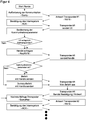
- FIG. 4 shows the sequence of an extended Access Inventory, which additionally performs a check of communication parameters before the actual command (Access).
- the execution of a command, in particular a write command for initializing the UII is thus linked to an additional condition, which is derived from a property of the transponder or the connection to the transponder.
- Examples of communication parameters to be tested are the level (RSSI), the phase or an angle in which the transponder is located (DoA), these communication parameters being able to be tested individually or in combinations. As a condition, for example, it may be required that these values lie in a certain corridor.
- the comparison value is either based on communication parameters that previously existed in an inventory FIG. 2 were recorded. Then, so to speak, the Transponder of the previous Inventory recognized even with matching UII on the basis of their communication parameters.
- transponders can be brought into an order on the basis of the communication parameters and a transponder can be selected at a specific position in this sequence or the sequence can be processed.
- DoA DoA
- RSSI Order is too weak, which in some applications corresponds to near-to-far.
- Auxiliary variables are also conceivable, such as an arrangement of transponders, which is determined from plausibility of images of a camera operated in parallel, or a manual selection in a graphical user interface with visualization of transponder positions.
- the condition on the communication parameters is then a priori set to provide singulation, such as by setting a fixed, very narrow angle corridor or a high RSSI threshold. It is then virtually unimaginable that this condition is coincidentally fulfilled by a plurality of transponders, but simply possible to suitably place a transponder to be initialized, for example, with a UII.
- the extended access inventory makes it possible to select whether a transponder with the desired data and in particular an initial UII is to be written directly during an inventory, in particular at the time of UII transmission, even if the transponders, including their UII, are identical .
- Different transponders with identical UII respond during inventory within different slots.
- the communication characteristics or communication parameters such as RSSI, phase angle or DoA can be determined and checked for each of the transponders.
- a responding transponder must meet certain specifications of the communication parameters to actually get the command.
- a separation is possible even with identical UII. This is used in particular during the initialization, in order to provide the same UIIs at the factory and actually once within the transponder population.
- the RFID communication can also be carried out according to the standard and thus without checking communication parameters, because the UII is sufficient for isolation.
Landscapes
- Engineering & Computer Science (AREA)
- Physics & Mathematics (AREA)
- Toxicology (AREA)
- Health & Medical Sciences (AREA)
- General Physics & Mathematics (AREA)
- Theoretical Computer Science (AREA)
- Electromagnetism (AREA)
- Computer Vision & Pattern Recognition (AREA)
- Artificial Intelligence (AREA)
- General Health & Medical Sciences (AREA)
- Computer Networks & Wireless Communication (AREA)
- Signal Processing (AREA)
- General Engineering & Computer Science (AREA)
- Computer Security & Cryptography (AREA)
- Near-Field Transmission Systems (AREA)
Claims (13)
- Dispositif RFID (10) pour la plage UHF selon ISO 18000-6 pour communiquer avec au moins un transpondeur RFID (12), qui comprend un émetteur-récepteur RFID (16) pour émettre et recevoir des signaux RFID, et une unité de commande (18) réalisée pour coder une information RFID dans le signal RFID selon un protocole RFID ou pour la lire dans le signal RFID, et dans laquelle est implémenté un procédé d'individualisation pour émettre une instruction à un seul transpondeur RFID respectif (12) en se basant sur un paramètre d'identification (UII),
caractérisé en ce que
afin d'élargir le procédé d'individualisation, l'unité de commande (18) est réalisée pour ajouter à un inventaire un contrôle supplémentaire d'un paramètre de communication du signal RFID lui-même, qui est indépendant des informations RFID codées dans le signal RFID, de sorte que même une individualisation de transpondeurs RFID (12) ayant des paramètres d'identification identiques (UII) est possible. - Dispositif RFID (10) selon la revendication 1,
dans lequel
le paramètre de communication est un niveau ou une phase du signal RFID. - Dispositif RFID (10) selon la revendication 1 ou 2,
dans lequel
le paramètre de communication a une direction depuis laquelle le signal RFID est reçu. - Dispositif RFID (10) selon l'une des revendications précédentes,
dans lequel
l'unité de commande (18) est réalisée pour déterminer le paramètre de communication pendant un inventaire. - Dispositif RFID (10) selon la revendication 4,
dans lequel
l'inventaire subdivise une durée temporelle d'un tour en une multitude de slots, et l'unité de commande (18) - sous réserve que précisément un transpondeur RFID (12) réponde - confirme la réponse dans chaque slot et reçoit ensuite le paramètre d'identification univoque UII du transpondeur RFID (12) qui répond. - Dispositif RFID (10) selon l'une des revendications précédentes,
dans lequel
l'unité de commande (18) est réalisée pour donner à un transpondeur RFID (12) déterminé une instruction d'écriture pour poser le paramètre d'identification UII univoque. - Dispositif RFID (10) selon l'une des revendications précédentes,
dans lequel
l'unité de commande (18) est réalisée pour sélectionner des transpondeurs RFID (12) ayant un paramètre d'identification UII univoque donné. - Dispositif RFID (10) selon l'une des revendications précédentes,
dans lequel
l'unité de commande (18) est réalisée pour donner à un transpondeur RFID (12) qui répond et qui a un paramètre d'identification UII univoque correct mais qui n'a pas de paramètre de communication adéquat, une instruction vide qui ne modifie rien dans le transpondeur RFID (12) mais qui satisfait le protocole RFID. - Dispositif RFID (10) selon l'une des revendications précédentes,
dans lequel
l'unité de commande (18) est réalisée pour démarrer une initialisation avec des instructions d'écriture pour poser les paramètres d'identification UII univoques lorsque plus d'un transpondeur RFID (12) ayant le même paramètre d'identification UII univoque répondent. - Procédé pour communiquer avec au moins un transpondeur RFID (12)
dans la plage UHF selon ISO 18000-6,
dans lequel
des signaux RFID sont émis au transpondeur RFID (12) et sont reçus du transpondeur RFID (12), et
une information RFID est codée dans le signal RFID selon un protocole RFID,
au moyen d'un procédé d'individualisation une instruction est donnée à un seul transpondeur RFID (12) respectif en se basant sur un paramètre d'identification (UII),
caractérisé en ce que
afin d'élargir le procédé d'individualisation, un contrôle supplémentaire d'un paramètre de communication du signal RFID lui-même est ajouté à un inventaire, qui est indépendant des informations RFID codées dans le signal RFID, de sorte que même des transpondeurs RFID (12) ayant des paramètres d'identification identiques (UII) sont individualisés. - Procédé selon la revendication 10,
dans lequel
le paramètre de communication est un niveau du signal RFID, une phase ou une direction depuis laquelle le signal RFID est reçu. - Procédé selon la revendication 10 ou 11,
dans lequel
le protocole RFID est celui de la norme ISO 18000-6,
le paramètre de communication est déterminé pendant un inventaire et est contrôlé dans l'inventaire élargi par le contrôle supplémentaire du paramètre de communication, pour émettre des instructions à un transpondeur RFID (12) déterminé. - Procédé selon la revendication 12,
dans lequel
pour initialiser une population de transpondeurs RFID (12), dans l'inventaire élargi, une instruction d'écriture respective pour poser le paramètre d'identification UII univoque est donnée individuellement aux transpondeurs RFID (12).
Applications Claiming Priority (1)
| Application Number | Priority Date | Filing Date | Title |
|---|---|---|---|
| DE102016113302.7A DE102016113302A1 (de) | 2016-07-19 | 2016-07-19 | RFID-Vorrichtung und Verfahren zum Kommunizieren mit mindestens einem RFID-Transponder |
Publications (2)
| Publication Number | Publication Date |
|---|---|
| EP3273381A1 EP3273381A1 (fr) | 2018-01-24 |
| EP3273381B1 true EP3273381B1 (fr) | 2018-11-07 |
Family
ID=59101321
Family Applications (1)
| Application Number | Title | Priority Date | Filing Date |
|---|---|---|---|
| EP17176998.7A Active EP3273381B1 (fr) | 2016-07-19 | 2017-06-20 | Dispositif rfid et procédé de communication avec au moins un transpondeur rfid |
Country Status (7)
| Country | Link |
|---|---|
| US (1) | US10395075B2 (fr) |
| EP (1) | EP3273381B1 (fr) |
| JP (1) | JP6535049B2 (fr) |
| KR (1) | KR102053721B1 (fr) |
| CN (1) | CN107635212B (fr) |
| DE (1) | DE102016113302A1 (fr) |
| DK (1) | DK3273381T3 (fr) |
Families Citing this family (1)
| Publication number | Priority date | Publication date | Assignee | Title |
|---|---|---|---|---|
| EP4148616B1 (fr) * | 2021-09-10 | 2023-08-16 | Sick Ag | Communication avec un transpondeur rfid |
Family Cites Families (20)
| Publication number | Priority date | Publication date | Assignee | Title |
|---|---|---|---|---|
| US20050099267A1 (en) * | 2002-03-13 | 2005-05-12 | Franz Amtmann | Communication station for communication with transponders and further communication stations with the aid of different transmission parameters |
| ATE451658T1 (de) * | 2003-07-22 | 2009-12-15 | Nokia Corp | Lesereinrichtung für einen hochfrequenz- identifikations-transponder mit transponder- funktionalität |
| US7398054B2 (en) * | 2003-08-29 | 2008-07-08 | Zih Corp. | Spatially selective UHF near field microstrip coupler device and RFID systems using device |
| US8596532B2 (en) * | 2004-06-10 | 2013-12-03 | Zih Corp. | Apparatus and method for communicating with an RFID transponder |
| DE102004041437B3 (de) * | 2004-08-27 | 2006-03-09 | Atmel Germany Gmbh | Verfahren zur Auswahl eines oder mehrerer Transponder |
| US20060284727A1 (en) * | 2005-06-16 | 2006-12-21 | Psc Scanning, Inc. | Method and system with functionality for finding range between an electronic tag reader and tag |
| US8653946B2 (en) * | 2006-05-10 | 2014-02-18 | Electronics And Telecommunications Research Institute | Passive RFID reader and operation control method therefor |
| JP4907268B2 (ja) * | 2006-08-29 | 2012-03-28 | 株式会社日立製作所 | 無線icメモリ、無線icメモリ用のアクセス装置及びアクセス制御方法 |
| US20080280560A1 (en) * | 2007-05-09 | 2008-11-13 | Micron Technology, Inc. | Method and system of placing a rfid tag in a continuous transmission mode |
| JP5119870B2 (ja) * | 2007-11-09 | 2013-01-16 | ブラザー工業株式会社 | 無線タグ通信装置及び無線タグ通信システム |
| WO2009148273A2 (fr) * | 2008-06-04 | 2009-12-10 | 한국전자통신연구원 | Étiquette rfid pour service rfid et procédé de service rfid correspondant |
| NZ593545A (en) * | 2008-11-20 | 2014-07-25 | Reed Licensing Pty Ltd | Radio frequency transponder system |
| US8493182B2 (en) * | 2009-10-16 | 2013-07-23 | Rf Controls, Llc | Phase ranging RFID location system |
| DE102010060148A1 (de) * | 2010-10-25 | 2012-04-26 | Sick Ag | RFID-Lesevorrichtung und Lese- und Zuordnungsverfahren |
| DE102011000852A1 (de) * | 2011-02-21 | 2012-08-23 | Sick Ag | RFID-Lesetunnel und Verfahren zum Auslesen von RFID-Transpondern |
| ES2460917T3 (es) * | 2011-08-25 | 2014-05-16 | Siemens Aktiengesellschaft | Procedimiento y aparato de escritura-lectura para una disposición con varios transpondedores legibles sin contacto |
| US20130127601A1 (en) * | 2011-11-17 | 2013-05-23 | Larry D. Thomas, Jr. | RFID Reader Using Single System on a Chip |
| US20140347165A1 (en) * | 2013-05-23 | 2014-11-27 | Hand Held Products, Inc. | Rfid tag range control |
| US9576167B2 (en) * | 2014-06-12 | 2017-02-21 | The Boeing Company | Locating parts with electromagnetic identification (EMID) tags for contextual visualization |
| FI126136B (en) * | 2014-09-03 | 2016-07-15 | Metso Flow Control Oy | Integrated passive RFID transponder chip and passive RFID sensor tag |
-
2016
- 2016-07-19 DE DE102016113302.7A patent/DE102016113302A1/de not_active Withdrawn
-
2017
- 2017-06-01 JP JP2017108971A patent/JP6535049B2/ja active Active
- 2017-06-20 EP EP17176998.7A patent/EP3273381B1/fr active Active
- 2017-06-20 DK DK17176998.7T patent/DK3273381T3/en active
- 2017-06-28 CN CN201710507273.9A patent/CN107635212B/zh active Active
- 2017-07-07 US US15/644,337 patent/US10395075B2/en active Active
- 2017-07-18 KR KR1020170091125A patent/KR102053721B1/ko active IP Right Grant
Non-Patent Citations (1)
| Title |
|---|
| None * |
Also Published As
| Publication number | Publication date |
|---|---|
| JP6535049B2 (ja) | 2019-06-26 |
| CN107635212A (zh) | 2018-01-26 |
| US20180025191A1 (en) | 2018-01-25 |
| DK3273381T3 (en) | 2019-01-21 |
| KR102053721B1 (ko) | 2019-12-09 |
| US10395075B2 (en) | 2019-08-27 |
| DE102016113302A1 (de) | 2018-01-25 |
| JP2018060514A (ja) | 2018-04-12 |
| CN107635212B (zh) | 2020-05-12 |
| KR20180009723A (ko) | 2018-01-29 |
| EP3273381A1 (fr) | 2018-01-24 |
Similar Documents
| Publication | Publication Date | Title |
|---|---|---|
| WO2003015006A2 (fr) | Procede de transmission de donnees entre un appareil de lecture/d'ecriture et une memoire de donnees, application d'un procede dans un systeme d'identification, appareil de lecture/d'ecriture et memoire de donnees mobile pour un tel systeme d'identification | |
| EP3291144B1 (fr) | Dispositif rfid et procede de reconnaissance d'occupation de casier | |
| DE102012212856B4 (de) | Verfahren und Schreib-/Lesegerät zur Erfassung, Selektion und Meldung von zumindest einem aus einer Mehrzahl von berührungslos auslesbaren Transpondern | |
| EP3219019B1 (fr) | Dispositif d'antennes, système de détection et methode pour émettre un signal radio | |
| DE102004009508A1 (de) | Funkidentifikationssystem, Verfahren zum Durchführen einer Funkidentifikation und ein Programm für eine Funkidentifikation | |
| EP2927838B1 (fr) | Dispositif et procédé d'identification et de localisation d'objets | |
| EP1586917A2 (fr) | Méthode pour faire un choix entre un ou plusieurs répondeurs | |
| EP1836654B1 (fr) | Procede de localisation d'un transpondeur a base de retrodiffusion | |
| EP3273381B1 (fr) | Dispositif rfid et procédé de communication avec au moins un transpondeur rfid | |
| EP3279686B1 (fr) | Dispositif rfid permettant de communiquer avec des transpondeurs rfid et procédé d'attribution de transpondeurs rfid | |
| WO2009013001A1 (fr) | Procédé et dispositif de transfert sans contact de données depuis et/ou vers plusieurs supports de données ou d'informations étant de préférence sous la forme d'étiquettes rfid | |
| EP1735735B1 (fr) | Procede et dispositif pour reconnaitre des etats fonctionnels dans des systemes rfid et des systemes de teledetection | |
| EP2562676B1 (fr) | Procédé et appareil de lecture-écriture pour un agencement doté d'une multitude de transpondeur lisibles sans contact | |
| DE102017130287A1 (de) | Antwortgerät, abfragegerät, verfahren zur steuerung des antwortgeräts, verfahren zur steuerung des abfragegeräts, informationsverarbeitungsprogramm und aufzeichnungsmedium | |
| EP2500850A1 (fr) | Procédé et système destinés à la surveillance d'objets | |
| DE102019133973A1 (de) | Systeme und verfahren zur verwaltung einer population von rfid-etiketten | |
| DE102014212108A1 (de) | Transportbehälter mit innenvolumen-überwachungsanordnung und logistiksystem | |
| WO2022089798A1 (fr) | Procédé d'exploitation d'un système de radiolocalisation, système de radiolocalisation et station de base | |
| EP3414588A1 (fr) | Dispositif et procédé de détermination de la position d'un émetteur par rapport à une zone de détection | |
| EP4330709A1 (fr) | Localisation ulb avec synchronisation d'ancrage ulb indépendante | |
| EP2631848B1 (fr) | Agencement de transpondeur, dispositif d'émission et de réception et procédé de fonctionnement d'un dispositif d'émission et de réception | |
| EP3015755A1 (fr) | Élément RFID, système d'émetteur/récepteur RFID ainsi que commutateur de sécurité | |
| EP2990989B1 (fr) | Méthode et appareil de lecture/écriture pour séléctionner une étiquette sans fil | |
| EP3077954B1 (fr) | Dispositif de communication servant à identifier et/ou localiser un transpondeur rfid | |
| DE102016202144B3 (de) | Lesegerät zum Lesen von Informationen aus einem Funketikett und zugehöriges Leseverfahren |
Legal Events
| Date | Code | Title | Description |
|---|---|---|---|
| PUAI | Public reference made under article 153(3) epc to a published international application that has entered the european phase |
Free format text: ORIGINAL CODE: 0009012 |
|
| STAA | Information on the status of an ep patent application or granted ep patent |
Free format text: STATUS: THE APPLICATION HAS BEEN PUBLISHED |
|
| AK | Designated contracting states |
Kind code of ref document: A1 Designated state(s): AL AT BE BG CH CY CZ DE DK EE ES FI FR GB GR HR HU IE IS IT LI LT LU LV MC MK MT NL NO PL PT RO RS SE SI SK SM TR |
|
| AX | Request for extension of the european patent |
Extension state: BA ME |
|
| STAA | Information on the status of an ep patent application or granted ep patent |
Free format text: STATUS: REQUEST FOR EXAMINATION WAS MADE |
|
| 17P | Request for examination filed |
Effective date: 20180420 |
|
| RBV | Designated contracting states (corrected) |
Designated state(s): AL AT BE BG CH CY CZ DE DK EE ES FI FR GB GR HR HU IE IS IT LI LT LU LV MC MK MT NL NO PL PT RO RS SE SI SK SM TR |
|
| GRAP | Despatch of communication of intention to grant a patent |
Free format text: ORIGINAL CODE: EPIDOSNIGR1 |
|
| STAA | Information on the status of an ep patent application or granted ep patent |
Free format text: STATUS: GRANT OF PATENT IS INTENDED |
|
| RIC1 | Information provided on ipc code assigned before grant |
Ipc: G06K 7/10 20060101AFI20180516BHEP Ipc: G06K 17/00 20060101ALI20180516BHEP |
|
| INTG | Intention to grant announced |
Effective date: 20180608 |
|
| GRAS | Grant fee paid |
Free format text: ORIGINAL CODE: EPIDOSNIGR3 |
|
| GRAA | (expected) grant |
Free format text: ORIGINAL CODE: 0009210 |
|
| STAA | Information on the status of an ep patent application or granted ep patent |
Free format text: STATUS: THE PATENT HAS BEEN GRANTED |
|
| AK | Designated contracting states |
Kind code of ref document: B1 Designated state(s): AL AT BE BG CH CY CZ DE DK EE ES FI FR GB GR HR HU IE IS IT LI LT LU LV MC MK MT NL NO PL PT RO RS SE SI SK SM TR |
|
| REG | Reference to a national code |
Ref country code: GB Ref legal event code: FG4D Free format text: NOT ENGLISH |
|
| REG | Reference to a national code |
Ref country code: CH Ref legal event code: EP Ref country code: AT Ref legal event code: REF Ref document number: 1062972 Country of ref document: AT Kind code of ref document: T Effective date: 20181115 |
|
| REG | Reference to a national code |
Ref country code: DE Ref legal event code: R096 Ref document number: 502017000325 Country of ref document: DE |
|
| REG | Reference to a national code |
Ref country code: IE Ref legal event code: FG4D Free format text: LANGUAGE OF EP DOCUMENT: GERMAN |
|
| REG | Reference to a national code |
Ref country code: NL Ref legal event code: FP |
|
| REG | Reference to a national code |
Ref country code: SE Ref legal event code: TRGR |
|
| REG | Reference to a national code |
Ref country code: DK Ref legal event code: T3 Effective date: 20190108 |
|
| REG | Reference to a national code |
Ref country code: LT Ref legal event code: MG4D |
|
| PG25 | Lapsed in a contracting state [announced via postgrant information from national office to epo] |
Ref country code: BG Free format text: LAPSE BECAUSE OF FAILURE TO SUBMIT A TRANSLATION OF THE DESCRIPTION OR TO PAY THE FEE WITHIN THE PRESCRIBED TIME-LIMIT Effective date: 20190207 Ref country code: LT Free format text: LAPSE BECAUSE OF FAILURE TO SUBMIT A TRANSLATION OF THE DESCRIPTION OR TO PAY THE FEE WITHIN THE PRESCRIBED TIME-LIMIT Effective date: 20181107 Ref country code: IS Free format text: LAPSE BECAUSE OF FAILURE TO SUBMIT A TRANSLATION OF THE DESCRIPTION OR TO PAY THE FEE WITHIN THE PRESCRIBED TIME-LIMIT Effective date: 20190307 Ref country code: NO Free format text: LAPSE BECAUSE OF FAILURE TO SUBMIT A TRANSLATION OF THE DESCRIPTION OR TO PAY THE FEE WITHIN THE PRESCRIBED TIME-LIMIT Effective date: 20190207 Ref country code: FI Free format text: LAPSE BECAUSE OF FAILURE TO SUBMIT A TRANSLATION OF THE DESCRIPTION OR TO PAY THE FEE WITHIN THE PRESCRIBED TIME-LIMIT Effective date: 20181107 Ref country code: ES Free format text: LAPSE BECAUSE OF FAILURE TO SUBMIT A TRANSLATION OF THE DESCRIPTION OR TO PAY THE FEE WITHIN THE PRESCRIBED TIME-LIMIT Effective date: 20181107 Ref country code: LV Free format text: LAPSE BECAUSE OF FAILURE TO SUBMIT A TRANSLATION OF THE DESCRIPTION OR TO PAY THE FEE WITHIN THE PRESCRIBED TIME-LIMIT Effective date: 20181107 Ref country code: HR Free format text: LAPSE BECAUSE OF FAILURE TO SUBMIT A TRANSLATION OF THE DESCRIPTION OR TO PAY THE FEE WITHIN THE PRESCRIBED TIME-LIMIT Effective date: 20181107 |
|
| PG25 | Lapsed in a contracting state [announced via postgrant information from national office to epo] |
Ref country code: PT Free format text: LAPSE BECAUSE OF FAILURE TO SUBMIT A TRANSLATION OF THE DESCRIPTION OR TO PAY THE FEE WITHIN THE PRESCRIBED TIME-LIMIT Effective date: 20190307 Ref country code: RS Free format text: LAPSE BECAUSE OF FAILURE TO SUBMIT A TRANSLATION OF THE DESCRIPTION OR TO PAY THE FEE WITHIN THE PRESCRIBED TIME-LIMIT Effective date: 20181107 Ref country code: AL Free format text: LAPSE BECAUSE OF FAILURE TO SUBMIT A TRANSLATION OF THE DESCRIPTION OR TO PAY THE FEE WITHIN THE PRESCRIBED TIME-LIMIT Effective date: 20181107 Ref country code: GR Free format text: LAPSE BECAUSE OF FAILURE TO SUBMIT A TRANSLATION OF THE DESCRIPTION OR TO PAY THE FEE WITHIN THE PRESCRIBED TIME-LIMIT Effective date: 20190208 |
|
| PG25 | Lapsed in a contracting state [announced via postgrant information from national office to epo] |
Ref country code: CZ Free format text: LAPSE BECAUSE OF FAILURE TO SUBMIT A TRANSLATION OF THE DESCRIPTION OR TO PAY THE FEE WITHIN THE PRESCRIBED TIME-LIMIT Effective date: 20181107 Ref country code: PL Free format text: LAPSE BECAUSE OF FAILURE TO SUBMIT A TRANSLATION OF THE DESCRIPTION OR TO PAY THE FEE WITHIN THE PRESCRIBED TIME-LIMIT Effective date: 20181107 |
|
| REG | Reference to a national code |
Ref country code: DE Ref legal event code: R097 Ref document number: 502017000325 Country of ref document: DE |
|
| PG25 | Lapsed in a contracting state [announced via postgrant information from national office to epo] |
Ref country code: SM Free format text: LAPSE BECAUSE OF FAILURE TO SUBMIT A TRANSLATION OF THE DESCRIPTION OR TO PAY THE FEE WITHIN THE PRESCRIBED TIME-LIMIT Effective date: 20181107 Ref country code: EE Free format text: LAPSE BECAUSE OF FAILURE TO SUBMIT A TRANSLATION OF THE DESCRIPTION OR TO PAY THE FEE WITHIN THE PRESCRIBED TIME-LIMIT Effective date: 20181107 Ref country code: SK Free format text: LAPSE BECAUSE OF FAILURE TO SUBMIT A TRANSLATION OF THE DESCRIPTION OR TO PAY THE FEE WITHIN THE PRESCRIBED TIME-LIMIT Effective date: 20181107 Ref country code: RO Free format text: LAPSE BECAUSE OF FAILURE TO SUBMIT A TRANSLATION OF THE DESCRIPTION OR TO PAY THE FEE WITHIN THE PRESCRIBED TIME-LIMIT Effective date: 20181107 |
|
| PLBE | No opposition filed within time limit |
Free format text: ORIGINAL CODE: 0009261 |
|
| STAA | Information on the status of an ep patent application or granted ep patent |
Free format text: STATUS: NO OPPOSITION FILED WITHIN TIME LIMIT |
|
| 26N | No opposition filed |
Effective date: 20190808 |
|
| PG25 | Lapsed in a contracting state [announced via postgrant information from national office to epo] |
Ref country code: MC Free format text: LAPSE BECAUSE OF FAILURE TO SUBMIT A TRANSLATION OF THE DESCRIPTION OR TO PAY THE FEE WITHIN THE PRESCRIBED TIME-LIMIT Effective date: 20181107 |
|
| PG25 | Lapsed in a contracting state [announced via postgrant information from national office to epo] |
Ref country code: TR Free format text: LAPSE BECAUSE OF FAILURE TO SUBMIT A TRANSLATION OF THE DESCRIPTION OR TO PAY THE FEE WITHIN THE PRESCRIBED TIME-LIMIT Effective date: 20181107 |
|
| PG25 | Lapsed in a contracting state [announced via postgrant information from national office to epo] |
Ref country code: IE Free format text: LAPSE BECAUSE OF NON-PAYMENT OF DUE FEES Effective date: 20190620 |
|
| PG25 | Lapsed in a contracting state [announced via postgrant information from national office to epo] |
Ref country code: LU Free format text: LAPSE BECAUSE OF NON-PAYMENT OF DUE FEES Effective date: 20190620 |
|
| PG25 | Lapsed in a contracting state [announced via postgrant information from national office to epo] |
Ref country code: CY Free format text: LAPSE BECAUSE OF FAILURE TO SUBMIT A TRANSLATION OF THE DESCRIPTION OR TO PAY THE FEE WITHIN THE PRESCRIBED TIME-LIMIT Effective date: 20181107 |
|
| PG25 | Lapsed in a contracting state [announced via postgrant information from national office to epo] |
Ref country code: MT Free format text: LAPSE BECAUSE OF FAILURE TO SUBMIT A TRANSLATION OF THE DESCRIPTION OR TO PAY THE FEE WITHIN THE PRESCRIBED TIME-LIMIT Effective date: 20181107 Ref country code: HU Free format text: LAPSE BECAUSE OF FAILURE TO SUBMIT A TRANSLATION OF THE DESCRIPTION OR TO PAY THE FEE WITHIN THE PRESCRIBED TIME-LIMIT; INVALID AB INITIO Effective date: 20170620 |
|
| PG25 | Lapsed in a contracting state [announced via postgrant information from national office to epo] |
Ref country code: SI Free format text: LAPSE BECAUSE OF FAILURE TO SUBMIT A TRANSLATION OF THE DESCRIPTION OR TO PAY THE FEE WITHIN THE PRESCRIBED TIME-LIMIT Effective date: 20181107 |
|
| PG25 | Lapsed in a contracting state [announced via postgrant information from national office to epo] |
Ref country code: MK Free format text: LAPSE BECAUSE OF FAILURE TO SUBMIT A TRANSLATION OF THE DESCRIPTION OR TO PAY THE FEE WITHIN THE PRESCRIBED TIME-LIMIT Effective date: 20181107 |
|
| PGFP | Annual fee paid to national office [announced via postgrant information from national office to epo] |
Ref country code: NL Payment date: 20230620 Year of fee payment: 7 Ref country code: FR Payment date: 20230622 Year of fee payment: 7 Ref country code: DK Payment date: 20230621 Year of fee payment: 7 Ref country code: DE Payment date: 20230620 Year of fee payment: 7 |
|
| PGFP | Annual fee paid to national office [announced via postgrant information from national office to epo] |
Ref country code: SE Payment date: 20230622 Year of fee payment: 7 Ref country code: AT Payment date: 20230616 Year of fee payment: 7 |
|
| PGFP | Annual fee paid to national office [announced via postgrant information from national office to epo] |
Ref country code: BE Payment date: 20230619 Year of fee payment: 7 |
|
| PGFP | Annual fee paid to national office [announced via postgrant information from national office to epo] |
Ref country code: IT Payment date: 20230630 Year of fee payment: 7 Ref country code: GB Payment date: 20230622 Year of fee payment: 7 Ref country code: CH Payment date: 20230702 Year of fee payment: 7 |