EP3273055A1 - Systèmes et procédés de correction de l'induction pour commande de turbine éolienne assistée par lidar - Google Patents
Systèmes et procédés de correction de l'induction pour commande de turbine éolienne assistée par lidar Download PDFInfo
- Publication number
- EP3273055A1 EP3273055A1 EP17179934.9A EP17179934A EP3273055A1 EP 3273055 A1 EP3273055 A1 EP 3273055A1 EP 17179934 A EP17179934 A EP 17179934A EP 3273055 A1 EP3273055 A1 EP 3273055A1
- Authority
- EP
- European Patent Office
- Prior art keywords
- wind
- turbine
- induction
- lidar
- model
- Prior art date
- Legal status (The legal status is an assumption and is not a legal conclusion. Google has not performed a legal analysis and makes no representation as to the accuracy of the status listed.)
- Granted
Links
- 230000006698 induction Effects 0.000 title claims abstract description 294
- 238000000034 method Methods 0.000 title claims abstract description 67
- 238000012937 correction Methods 0.000 claims abstract description 87
- 230000000694 effects Effects 0.000 claims abstract description 71
- 238000005259 measurement Methods 0.000 claims description 48
- 238000003860 storage Methods 0.000 claims description 31
- 230000003111 delayed effect Effects 0.000 claims description 17
- 238000004519 manufacturing process Methods 0.000 abstract description 3
- 230000008569 process Effects 0.000 description 20
- 230000006870 function Effects 0.000 description 16
- 238000011144 upstream manufacturing Methods 0.000 description 16
- 238000013459 approach Methods 0.000 description 12
- 230000003068 static effect Effects 0.000 description 10
- 238000012545 processing Methods 0.000 description 9
- 230000009471 action Effects 0.000 description 8
- 230000008859 change Effects 0.000 description 7
- 230000001419 dependent effect Effects 0.000 description 6
- 230000001133 acceleration Effects 0.000 description 5
- 238000001514 detection method Methods 0.000 description 5
- 230000010354 integration Effects 0.000 description 5
- 238000004458 analytical method Methods 0.000 description 4
- 230000007423 decrease Effects 0.000 description 4
- 238000001914 filtration Methods 0.000 description 4
- 230000007246 mechanism Effects 0.000 description 4
- 238000012935 Averaging Methods 0.000 description 3
- 230000006399 behavior Effects 0.000 description 3
- 230000005540 biological transmission Effects 0.000 description 3
- 230000004044 response Effects 0.000 description 3
- 238000004088 simulation Methods 0.000 description 3
- 230000003139 buffering effect Effects 0.000 description 2
- 238000004891 communication Methods 0.000 description 2
- 230000006866 deterioration Effects 0.000 description 2
- 230000003993 interaction Effects 0.000 description 2
- 239000002245 particle Substances 0.000 description 2
- 230000001902 propagating effect Effects 0.000 description 2
- 230000006978 adaptation Effects 0.000 description 1
- 230000003044 adaptive effect Effects 0.000 description 1
- 239000000443 aerosol Substances 0.000 description 1
- 230000008901 benefit Effects 0.000 description 1
- 230000001413 cellular effect Effects 0.000 description 1
- 238000010219 correlation analysis Methods 0.000 description 1
- 230000007850 degeneration Effects 0.000 description 1
- 238000010586 diagram Methods 0.000 description 1
- 238000005516 engineering process Methods 0.000 description 1
- 239000000835 fiber Substances 0.000 description 1
- 239000002803 fossil fuel Substances 0.000 description 1
- 230000003116 impacting effect Effects 0.000 description 1
- 239000004973 liquid crystal related substance Substances 0.000 description 1
- 238000013507 mapping Methods 0.000 description 1
- 238000005457 optimization Methods 0.000 description 1
- 230000002093 peripheral effect Effects 0.000 description 1
- 238000005070 sampling Methods 0.000 description 1
- 230000035945 sensitivity Effects 0.000 description 1
- 230000001360 synchronised effect Effects 0.000 description 1
- 230000007704 transition Effects 0.000 description 1
Images


Classifications
-
- F—MECHANICAL ENGINEERING; LIGHTING; HEATING; WEAPONS; BLASTING
- F03—MACHINES OR ENGINES FOR LIQUIDS; WIND, SPRING, OR WEIGHT MOTORS; PRODUCING MECHANICAL POWER OR A REACTIVE PROPULSIVE THRUST, NOT OTHERWISE PROVIDED FOR
- F03D—WIND MOTORS
- F03D7/00—Controlling wind motors
- F03D7/02—Controlling wind motors the wind motors having rotation axis substantially parallel to the air flow entering the rotor
- F03D7/0204—Controlling wind motors the wind motors having rotation axis substantially parallel to the air flow entering the rotor for orientation in relation to wind direction
-
- F—MECHANICAL ENGINEERING; LIGHTING; HEATING; WEAPONS; BLASTING
- F03—MACHINES OR ENGINES FOR LIQUIDS; WIND, SPRING, OR WEIGHT MOTORS; PRODUCING MECHANICAL POWER OR A REACTIVE PROPULSIVE THRUST, NOT OTHERWISE PROVIDED FOR
- F03D—WIND MOTORS
- F03D7/00—Controlling wind motors
- F03D7/02—Controlling wind motors the wind motors having rotation axis substantially parallel to the air flow entering the rotor
- F03D7/022—Adjusting aerodynamic properties of the blades
- F03D7/0224—Adjusting blade pitch
-
- F—MECHANICAL ENGINEERING; LIGHTING; HEATING; WEAPONS; BLASTING
- F03—MACHINES OR ENGINES FOR LIQUIDS; WIND, SPRING, OR WEIGHT MOTORS; PRODUCING MECHANICAL POWER OR A REACTIVE PROPULSIVE THRUST, NOT OTHERWISE PROVIDED FOR
- F03D—WIND MOTORS
- F03D7/00—Controlling wind motors
- F03D7/02—Controlling wind motors the wind motors having rotation axis substantially parallel to the air flow entering the rotor
- F03D7/04—Automatic control; Regulation
-
- G—PHYSICS
- G01—MEASURING; TESTING
- G01S—RADIO DIRECTION-FINDING; RADIO NAVIGATION; DETERMINING DISTANCE OR VELOCITY BY USE OF RADIO WAVES; LOCATING OR PRESENCE-DETECTING BY USE OF THE REFLECTION OR RERADIATION OF RADIO WAVES; ANALOGOUS ARRANGEMENTS USING OTHER WAVES
- G01S17/00—Systems using the reflection or reradiation of electromagnetic waves other than radio waves, e.g. lidar systems
- G01S17/02—Systems using the reflection of electromagnetic waves other than radio waves
- G01S17/50—Systems of measurement based on relative movement of target
- G01S17/58—Velocity or trajectory determination systems; Sense-of-movement determination systems
-
- G—PHYSICS
- G01—MEASURING; TESTING
- G01S—RADIO DIRECTION-FINDING; RADIO NAVIGATION; DETERMINING DISTANCE OR VELOCITY BY USE OF RADIO WAVES; LOCATING OR PRESENCE-DETECTING BY USE OF THE REFLECTION OR RERADIATION OF RADIO WAVES; ANALOGOUS ARRANGEMENTS USING OTHER WAVES
- G01S17/00—Systems using the reflection or reradiation of electromagnetic waves other than radio waves, e.g. lidar systems
- G01S17/88—Lidar systems specially adapted for specific applications
- G01S17/95—Lidar systems specially adapted for specific applications for meteorological use
-
- F—MECHANICAL ENGINEERING; LIGHTING; HEATING; WEAPONS; BLASTING
- F05—INDEXING SCHEMES RELATING TO ENGINES OR PUMPS IN VARIOUS SUBCLASSES OF CLASSES F01-F04
- F05B—INDEXING SCHEME RELATING TO WIND, SPRING, WEIGHT, INERTIA OR LIKE MOTORS, TO MACHINES OR ENGINES FOR LIQUIDS COVERED BY SUBCLASSES F03B, F03D AND F03G
- F05B2220/00—Application
- F05B2220/30—Application in turbines
-
- F—MECHANICAL ENGINEERING; LIGHTING; HEATING; WEAPONS; BLASTING
- F05—INDEXING SCHEMES RELATING TO ENGINES OR PUMPS IN VARIOUS SUBCLASSES OF CLASSES F01-F04
- F05B—INDEXING SCHEME RELATING TO WIND, SPRING, WEIGHT, INERTIA OR LIKE MOTORS, TO MACHINES OR ENGINES FOR LIQUIDS COVERED BY SUBCLASSES F03B, F03D AND F03G
- F05B2260/00—Function
- F05B2260/84—Modelling or simulation
-
- F—MECHANICAL ENGINEERING; LIGHTING; HEATING; WEAPONS; BLASTING
- F05—INDEXING SCHEMES RELATING TO ENGINES OR PUMPS IN VARIOUS SUBCLASSES OF CLASSES F01-F04
- F05B—INDEXING SCHEME RELATING TO WIND, SPRING, WEIGHT, INERTIA OR LIKE MOTORS, TO MACHINES OR ENGINES FOR LIQUIDS COVERED BY SUBCLASSES F03B, F03D AND F03G
- F05B2270/00—Control
- F05B2270/10—Purpose of the control system
- F05B2270/20—Purpose of the control system to optimise the performance of a machine
-
- F—MECHANICAL ENGINEERING; LIGHTING; HEATING; WEAPONS; BLASTING
- F05—INDEXING SCHEMES RELATING TO ENGINES OR PUMPS IN VARIOUS SUBCLASSES OF CLASSES F01-F04
- F05B—INDEXING SCHEME RELATING TO WIND, SPRING, WEIGHT, INERTIA OR LIKE MOTORS, TO MACHINES OR ENGINES FOR LIQUIDS COVERED BY SUBCLASSES F03B, F03D AND F03G
- F05B2270/00—Control
- F05B2270/30—Control parameters, e.g. input parameters
- F05B2270/32—Wind speeds
-
- F—MECHANICAL ENGINEERING; LIGHTING; HEATING; WEAPONS; BLASTING
- F05—INDEXING SCHEMES RELATING TO ENGINES OR PUMPS IN VARIOUS SUBCLASSES OF CLASSES F01-F04
- F05B—INDEXING SCHEME RELATING TO WIND, SPRING, WEIGHT, INERTIA OR LIKE MOTORS, TO MACHINES OR ENGINES FOR LIQUIDS COVERED BY SUBCLASSES F03B, F03D AND F03G
- F05B2270/00—Control
- F05B2270/40—Type of control system
- F05B2270/404—Type of control system active, predictive, or anticipative
-
- F—MECHANICAL ENGINEERING; LIGHTING; HEATING; WEAPONS; BLASTING
- F05—INDEXING SCHEMES RELATING TO ENGINES OR PUMPS IN VARIOUS SUBCLASSES OF CLASSES F01-F04
- F05B—INDEXING SCHEME RELATING TO WIND, SPRING, WEIGHT, INERTIA OR LIKE MOTORS, TO MACHINES OR ENGINES FOR LIQUIDS COVERED BY SUBCLASSES F03B, F03D AND F03G
- F05B2270/00—Control
- F05B2270/80—Devices generating input signals, e.g. transducers, sensors, cameras or strain gauges
- F05B2270/804—Optical devices
- F05B2270/8042—Lidar systems
-
- Y—GENERAL TAGGING OF NEW TECHNOLOGICAL DEVELOPMENTS; GENERAL TAGGING OF CROSS-SECTIONAL TECHNOLOGIES SPANNING OVER SEVERAL SECTIONS OF THE IPC; TECHNICAL SUBJECTS COVERED BY FORMER USPC CROSS-REFERENCE ART COLLECTIONS [XRACs] AND DIGESTS
- Y02—TECHNOLOGIES OR APPLICATIONS FOR MITIGATION OR ADAPTATION AGAINST CLIMATE CHANGE
- Y02E—REDUCTION OF GREENHOUSE GAS [GHG] EMISSIONS, RELATED TO ENERGY GENERATION, TRANSMISSION OR DISTRIBUTION
- Y02E10/00—Energy generation through renewable energy sources
- Y02E10/70—Wind energy
- Y02E10/72—Wind turbines with rotation axis in wind direction
-
- Y—GENERAL TAGGING OF NEW TECHNOLOGICAL DEVELOPMENTS; GENERAL TAGGING OF CROSS-SECTIONAL TECHNOLOGIES SPANNING OVER SEVERAL SECTIONS OF THE IPC; TECHNICAL SUBJECTS COVERED BY FORMER USPC CROSS-REFERENCE ART COLLECTIONS [XRACs] AND DIGESTS
- Y02—TECHNOLOGIES OR APPLICATIONS FOR MITIGATION OR ADAPTATION AGAINST CLIMATE CHANGE
- Y02P—CLIMATE CHANGE MITIGATION TECHNOLOGIES IN THE PRODUCTION OR PROCESSING OF GOODS
- Y02P70/00—Climate change mitigation technologies in the production process for final industrial or consumer products
- Y02P70/50—Manufacturing or production processes characterised by the final manufactured product
Definitions
- This disclosure relates generally to wind turbine control, and, more particularly, to methods and apparatus to correct rotor induction for Light Detection and Ranging (LIDAR)-assisted wind turbine control.
- LIDAR Light Detection and Ranging
- Wind power is considered to be one of the cleanest, most environmentally friendly energy sources presently available, and wind turbines have gained increased attention for at least these reasons. Wind turbines have received increased attention over the past couple of decades as an environmentally clean energy source that is not dependent on limited fossil fuels.
- Certain examples provide systems and methods to control a wind turbine and compensate for wind induction effects.
- Certain examples provide a method of controlling a wind turbine.
- the example method includes receiving wind speed data from a Light Detecting and Ranging (LIDAR, Lidar, or lidar) sensor.
- the example method includes receiving operating data indicative of wind turbine operation.
- the example method includes determining an apriori induction correction for wind turbine operating conditions with respect to the LIDAR wind speed data based on the operating data.
- the example method includes estimating a wind signal from the LIDAR sensor that is adjusted by the correction.
- the example method includes generating a control signal for a wind turbine based on the adjusted LIDAR estimated wind signal.
- Certain examples provide a tangible, computer-readable storage medium including instructions which, when executed by a processor, cause the processor to at least receive wind speed data from a Light Detecting and Ranging (LIDAR) sensor. Additionally, the example instructions, when executed, cause the processor to at least receive operating data indicative of wind turbine operation. The example instructions, when executed, cause the processor to at least determine an apriori induction correction for wind turbine operating conditions with respect to the LIDAR wind speed data based on the operating data. The example instructions, when executed, cause the processor to at least estimate a wind signal from the LIDAR sensor that is adjusted by the correction. The example instructions, when executed, cause the processor to at least generate a control signal for a wind turbine based on the adjusted LIDAR estimated wind signal.
- LIDAR Light Detecting and Ranging
- the example apparatus includes a wind estimation processor.
- the example wind estimation processor is particularly configured to receive wind speed data from a Light Detecting and Ranging (LIDAR) sensor.
- the example wind estimation processor is also particularly configured to receive operating data indicative of wind turbine operation.
- the example wind estimation processor is particularly configured to determine an apriori induction correction for wind turbine operating conditions with respect to the LIDAR wind speed data based on the operating data.
- the example wind estimation processor is particularly configured to estimate a wind signal from the LIDAR sensor that is adjusted by the correction.
- the example wind estimation processor is particularly configured to generate a control signal for a wind turbine controller based on the adjusted LIDAR estimated wind signal.
- a modern wind turbine typically includes a tower, a generator, a gearbox, a nacelle, and a rotor.
- the rotor typically includes a rotatable hub having one or more blades attached thereto.
- a pitch bearing is typically configured operably between the hub and the rotor blade to allow for rotation about a pitch axis.
- the rotor blades capture the kinetic energy of wind using known airfoil principles.
- the rotor blades transmit the kinetic energy as rotational energy to turn a shaft, which couples the rotor blades to a gearbox.
- the gearbox is not used, the rotor blades transmit the kinetic energy directly to the generator.
- the generator then converts the mechanical energy into electrical energy that may be deployed to a utility grid, for example.
- a power output of the generator increases with the wind speed until the wind speed reaches a threshold wind speed for the wind turbine.
- the generator operates at a rated power.
- the rated power is an output power, which the generator can operate with a level of fatigue or extreme load two-turbine components that have been predetermined to be acceptable for the turbine.
- the wind turbine may implement a control action, such as shutting down or de-rating the wind turbine to protect wind turbine components from damage.
- One or more sensors can be positioned on or near the wind turbine to detect wind conditions. For example, a wind speed sensor position on the wind turbine will measure wind gusts at substantially the same time as the wind gust strikes the rotor blades. As such, wind turbine operation adjustments are subject to a time lag between measurement of the wind gust and the control action. As a result, the wind gust may cause rotor acceleration that can create excessive turbine loading and fatigue. In some instances, the wind gust may cause the rotor speed or power output to exceed a trip limit before a wind turbine operation adjustment can be completed, thereby causing the wind turbine to shut down.
- Upwind measuring sensors such as light detection and ranging (LIDAR) sensors, can be used to address a time lag between measurement of the wind gusts and the control action.
- LIDAR light detection and ranging
- a change in wind acceleration can be measured upwind from the wind turbine, and the control action can be preemptively adjusted to compensate for the change in wind speed once the wind reaches the wind turbine.
- LIDAR is a surveying technology that measures distance and speed by illuminating a target with a laser light.
- LIDAR emits laser and/or three-dimensional scanning, which is reflected onto one or several targets.
- LIDAR can also be used to measure airflow, such as wind, by the reflection of the emitted light by particles present in the atmosphere and carried by the wind.
- a Doppler LIDAR system can be used to acquire wind speed, turbulence, wind veer, wind shear, and/or other wind profile data. Both pulsed and continuous wave Doppler LIDAR systems can be used. Pulsed Doppler LIDAR systems use signal timing to obtain distance resolution, and continuous wave Doppler LIDAR systems rely on detector focusing.
- the turbine control architecture includes feed-forward and/or feedback components using upwind speed measurements and/or wind speed measurements at the turbine site, respectively.
- the turbine control systems combine feed-forward components based on the upwind speed measurements and feedback components based on the wind speed measured at the turbine site. Prediction and analysis of wind speed, using techniques such as a LIDAR-based analysis, can help achieve high-performance turbine operation.
- one or more sensors may be used to detect an actual wind parameter upwind of the wind turbine.
- one or more LIDAR sensors can be used to detect the actual wind parameter, such as a wind gust, the wind speed, wind direction, wind acceleration, wind turbulence, a wind shear, a wind veer, a wake, etc.
- operating data indicative of current wind turbine operation is also provided to a processor to determine an estimated wind turbine condition.
- the wind turbine operating data can include, for example, wind turbine thrust, generator speed, torque, turbine blade pitch, etc.
- FIG. 1 illustrates an example of wind turbine 100.
- the example wind turbine 100 includes a rotor 112 having a plurality of blades 114 mounted on a hub 120.
- the wind turbine 100 also includes a nacelle 122 that is mounted on a tower 116.
- the rotor 112 is operatively coupled to an electrical generator via a drivetrain (not shown) housed within the nacelle 122.
- the tower 116 exposes the blades 114 to the wind (directionally represented by an arrow 126), which causes the blades 114 to rotate about an axis 128.
- the blades 114 transform kinetic energy of the wind into a rotational torque, which is further transformed into electrical energy via the electrical generator.
- FIG. 2 A simplified, internal view of an implementation of the example wind turbine 100 is illustrated in FIG. 2 .
- a generator 124 may be disposed within the nacelle 122.
- the generator 124 can be coupled to the rotor 112 to produce electric power from the rotational energy generated by the rotor 112.
- the rotor 112 can include a rotor shaft 134 for rotation therewith.
- the rotor shaft 134 may, in turn, be rotatably coupled to a generator shaft 136 of the generator 124 through a gearbox 138.
- the rotor shaft 134 can provide a low-speed, high-torque input to the gearbox 138 in response to rotation of the rotor blades 114 and a hub 120.
- the gearbox 138 may then be configured to convert the low-speed, high-torque input to a high-speed, low-torque output to drive the generator shaft 136 and the generator 124.
- the wind turbine 100 may also include a controller 130 centralized within the nacelle 122.
- the controller 130 may be located within any other component of the wind turbine 100 or at a location outside the wind turbine 100.
- the controller 130 may be communicatively coupled to one or more components of the wind turbine 100 in order to control operation of the component(s) and/or implement various correction actions as described herein.
- the example controller 130 can include a computer and/or other processing unit.
- the controller 130 can include computer-readable instructions that, when implemented, configure the controller 130 to perform various functions, such as receiving, transmitting, and/or executing wind turbine control signals.
- the controller 130 can be configured to control the operating modes (e.g., startup and/or shutdown sequences, etc.), de-rate the wind turbine, and/or control components of the wind turbine 100.
- each rotor blade 114 can also include a pitch adjustment mechanism 132 configured to rotate each rotor blade 114 about its pitch axis 133.
- each pitch adjustment mechanism may include a pitch drive motor 140 (e.g., any suitable electric, hydraulic, or pneumatic motor, etc.), a pitch drive gearbox 142, and a pitch drive pinion 144.
- the pitch drive motor 140 can be coupled to the pitch drive gearbox 142 so that the pitch drive motor 140 imparts mechanical force to the pitch drive gearbox 142.
- the pitch drive gearbox 142 may be coupled to the pitch drive pinion 144 for rotation with the pitch drive pinion 144.
- the pitch drive pinion 144 can, in turn, begin rotational engagement with a pitch bearing 146 coupled between the hub 120 and a corresponding rotor blade 114 such that rotation of the pitch drive pinion 144 causes rotation of the pitch bearing 146.
- rotation of the pitch drive motor 140 drives the pitch drive gearbox 142 and the pitch drive pinion 144, thereby rotating the pitch bearing 146 and the rotor blade 114 about a pitch axis 133.
- the wind turbine 110 includes one or more yaw drive mechanisms 166 communicatively coupled to the controller 130, with each yard drive mechanism(s) 166 configured to change an angle of the nacelle 122 relative to the wind (e.g., by engaging a yaw bearing 168 of the wind turbine 100).
- the example wind turbine 100 can include one or more sensors 148, 150, 152, 154 for measuring wind parameters upwind of the wind turbine 100.
- the sensor 148 is located on the hub 120 to measure actual wind parameters upwind of the wind turbine 100.
- the actual wind parameter can include a wind gust, a wind speed, a wind direction, a wind acceleration, a wind turbulence, a wind shear, a wind veer, etc.
- the one or more sensors 148-154 can include at least one LIDAR sensor to measure upwind parameters. For example, as shown in FIG.
- LIDAR sensor 148 is a measurement light detection and ranging device configured to scan an annular region around the wind turbine 100 and measure wind speed based upon reflection and/or scattering of light transmitted by the LIDAR sensor 148 from aerosol.
- a cone angle ( ⁇ ) and a range (R) of the LIDAR sensor 148 can be suitably selected to provide a desired accuracy of measurements as well as an acceptable sensitivity.
- the LIDAR sensor 148 is located on the hub 120 on which the blades 114 are mounted.
- one or more LIDAR sensors can also be located near the base of the wind turbine tower 116, on one or more of the wind turbine blades 114, on the nacelle 122, on the tower 116, and/or at any other suitable location.
- the LIDAR sensor 148 may be located in any suitable location on or near the wind turbine 100.
- the LIDAR sensor 148 can be configured to measuring wind parameter ahead of at least one specific portion of the wind turbine 100, such as a section of the blades 114 contributing to aerodynamic torque on the blades 114 (e.g., sections close to a tip of the blades 114). In the case of the points ahead of the blades 114 at which wind speed is measured by the LIDAR sensor 148, these examples are represented by a plane 172 shown in FIG. 1 .
- one or more of the sensors 148-154 can be other sensors capable of measuring wind parameters upwind of the wind turbine 100.
- the sensors 148-154 can include accelerometers, pressure sensors, angle of attack sensors, vibration sensors, miniaturized inertial measurement unit (MIMU) sensors, cameras, fiber optic systems, anemometers, wind vanes, sonic detection and ranging (SODAR) sensors, radio detection and ranging (RADAR), infrared lasers, radiometers, pitot tubes, radiosondes, etc.
- MIMU miniaturized inertial measurement unit
- SODAR sonic detection and ranging
- RADAR radio detection and ranging
- the term "monitor" and variations thereof indicate that sensors of the wind turbine 100 can be configured to provide a direct measurement of one or more parameters being monitored and/or an indirect measurement of such parameter(s).
- the sensors 148, 150, 152, 154 can be used to generate signals relating to parameter(s) being monitored, which can then be utilized by the controller 130 to determine an operating condition.
- a model-based control system one or more models are adapted to represent a motor/engine being controlled (e.g., a wind turbine, etc.).
- An adaptation of the model(s) allows the control system to make more informed and/or optimal decisions about how to adapt to and/or reconfigure the control when turbine operation is moved away from nominal conditions.
- An adaptive model-based control system can detect deterioration, faults, failures, and/or damage, and then take such information and incorporate it into the models, optimizations, objective functions, constraints, and/or parameters in the control system, such as in real time. This information allows the control system to take optimized or improved action given current turbine conditions.
- control systems can be updated and adapted in real time, they allow for a variety of deteriorations, falls, failures, and/or damages to be accommodated, rather than degenerations, faults, failures, and/or damages that have a priori solutions already programmed into the model(s) in the control system.
- model-based control systems are created by designing a model of each component and/or system that is to be controlled. For example, there may be a model of each engine component and system: turbine, combustor, etc. Each model includes features and/or dynamic characteristics about the component and/or system behavior over time (e.g., speed acceleration, torque, etc.). From the model(s), the system may control, estimate, correct, and/or identify output data based on the modeled information. Model-based diagnostics provide accurate turbine condition information relying on models and sensed parameters.
- Rotor induction refers to an effect of the wind turbine on air flow due to the operation of the turbine blades (e.g., a distortion in the wind field). Air flow close to the turbine blades is different from air flow further away from the turbine. Models can be constructed to illustrate wind flow with and without the wind turbine, and induction is the difference between the models. However, such a difference is hard to accurately obtain. Certain examples compute the difference based on turbine location and/or operation, effect(s) average, specific component analysis, time snapshot, and/or effect(s) over time, etc.
- this subtraction can be achieved using numerical simulation, in which free wind flow can be measured, stored, and simulated with or without one or several wind turbines. Induction effects can decay upstream of the turbine (e.g., at more than two rotor diameters upstream), and a magnitude of induction effect in the rotor plane can be up to 30% of the free-stream longitudinal wind speed, for example.
- simplification strategies For engineering modeling purposes, several levels of simplification can be made in order to provide a simplified, yet realistic description.
- One or more simplification strategies can be applied in successive levels implemented in different orders.
- Some example simplification strategies are as follows.
- modeling can focus on the induced wind field in the wind turbine rotor plane V induced (0,y,z,t). Focusing on the induced field in the wind turbine rotor plane can be sufficient to determine an aerodynamic state of the turbine rotor.
- the rotor plane induced wind field can be expressed in cylindrical coordinates, in which y and z are replaced by r (radial coordinate) and ⁇ (azimuthal coordinate) as V induced (r, ⁇ ,t).
- azimuthal variation can be averaged to express a rotor plane induced wind field that depends on radius only as V induced (r,t). In this model, effects of individual blade and eventual shear effects are averaged.
- V n ind (r,t) and V t ind (r,t) can be analyzed, while neglecting the radial component of the wind field.
- an average of induced flow over the radius r which can be expressed as V n ind,qs (t) and V t ind,qs (t), can be evaluated.
- the average can be weighted by a given shape factor, for example.
- a low-pass filtered and/or time averaged induced wind field can be obtained over a given period of time and/or for given wind turbine operating conditions.
- the filtered and/or time averaged induced wind field can be expressed as V n ⁇ nd ⁇ and V t ⁇ nd ⁇ .
- an evolution of low-pass filtered and/or time averaged induced wind field can be processed as a function of spatial distance to the wind turbine V t ind,qs (r,z).
- induction factors can be built by normalizing induced flow fields with respect to one or more wind speeds of reference.
- induction effects are important for remote sensor wind field estimation close to the blade/rotor of the wind turbine (e.g., wind turbine 100).
- Inputs provided by remote sensing and wind estimation can be used to calculate and correct for such induction effects.
- Inputs include a projection of wind onto a remote sensing geometry, a time of flight, a convection of distant wind to the rotor plane, and/or a reconstruction of wind speed, direction and shear, for example.
- Remote sensors such as LIDAR, RADAR, and/or SODAR utilize reflected properties of laser, radio and sound waves onto the atmosphere's particles to determine components or projection of a wind field on one or several measurement locations located remotely from a sensor.
- the laser, radio, and/or sound waves can be collimated to define discrete beams that form a measurement volume. A number and location of the measurement volume(s) and/or a sampling rate of measurement depends on a type of sensor used, for example.
- a pulsed Doppler Lidar sensor can be mounted onto the nacelle 122 of a wind turbine 100.
- the example pulsed Doppler Lidar sensor with five beams can measure a plurality of ranges (e.g., 10 different ranges, resulting in 50 measurement points across the 5 beams, etc.).
- the remote LIDAR sensor may be able to measure only specific components of the wind field (e.g., collinear or orthogonal to a beam, etc.).
- the remote sensor may measure over a volume compared to a point (e.g., a Lidar measurement volume can be a cylinder of 5cm radius and 30m length, etc.).
- the remote sensor may measure with an integration time (e.g., 0.25s, etc.).
- the remote sensor may measure one or several locations at a time during a scanning pattern (e.g., a one second scanning pattern, etc.).
- wind estimation for a wind turbine involves determining wind metrics representative of the wind field approaching the wind turbine 100 with a given preview time.
- Wind metrics can include rotor averaged wind speed, vertical and/or horizontal wind direction, vertical and/or horizontal shear, etc.
- wind estimation involves (a) a parametric wind model that represents quantities to be estimated and (b) a parametric propagation model that represents space/time propagation of a wind variation.
- An example wind propagation model can assume that wind patterns are travelling unchanged at a given wind speed (e.g., referred to as Taylor hypothesis). This hypothesis allows the example wind propagation model to use measurement from different distances upstream of the turbine with a time delay which accounts for their propagation. The hypothesis also allows the example wind propagation model to use measurement from one or several distances upstream of the turbine to predict the evolution of a wind metric as a function of time, assuming one time correspond to the wind metric observed and impacting by the turbine rotor.
- Determining a convection velocity of turbulence that is assumed to be constant or "frozen” can be important. In some examples, however, a mean flow wind speed can be a good approximation for the convection velocity.
- mean and dynamic induction models can be generated.
- a mean induction model can be used to estimate LIDAR wind speed, for example.
- the mean induction model can be used to correct LIDAR measurement for mean slow-down of wind velocity as it approaches the turbine (e.g., can be part of the wind model), for example.
- the mean induction model can be used to eventually correct the propagation speed for slow-down as the wind approaches the turbine, for example.
- FIGS. 3A-3B illustrate example graphs showing correlations between wind speed and induction ( FIG. 3A ) and between distance to turbine and wind speed ( FIG. 3B ).
- FIG. 3A As shown in the example graph 300 of FIG. 3A , as wind speed 310 increases, an induction effect 320 from the turbine 100 decreases.
- the induction A remains relatively constant at WS 1 and WS 2 but decreases exponentially at WS 3 .
- a value for an induction constant plateau is 1/3.
- wind speed 370 As shown in the example graph 350 of FIG. 3B , as distance to turbine 360 increases, wind speed 370 also increases. For example, wind speed 370 gradually increases from U 0 (1-A) to U 0 as the distance to turbine 360 increases from 0 to one distance interval corresponding to rotor diameter (1D) to 2D and 4D.
- FIGS. 4A-4B illustrate example propagation of wind disturbance and dynamic inflow effect.
- propagation of a gust of wind 410 at a predicted wind speed can be measured by a Lidar sensor 420.
- FIG. 4B shows how the Lidar 420 perceives a change of induction (e.g., due to a pitch action on one or several blades, etc.). If induction changes, all ranges are affected substantially at once, resulting in a lack of propagation that is to be corrected.
- propagation of the wind gust 410 is dictated by the Taylor hypothesis convection speed.
- the Taylor hypothesis means that the wind gust 410 is measured first by the farthest ranges (e.g., at time t1) and a few second later by the closest ranges (e.g., at time t2), which can be modelled by the above-described propagation model.
- a change of pitch 430 causes a discontinuity in the wake 440 of the wind turbine 100, which will be progressively convected downstream of the wind turbine 100.
- the induction gradually changes 450 (e.g., from t1 to t2) with a delay corresponding to the wake propagation.
- the Lidar 420 measures these induced changes in wind speed at all ranges at the same time (e.g., induction effects propagate upstream at the speed of sound (e.g., 340m/s), which can be considered very fast compared to convection speed (e.g., 10m/s)).
- the Lidar sensor 420 can be mounted on the nacelle 122 of the wind turbine 100 and/or near the wind turbine in a wind farm, for example.
- the Lidar 420 can be measuring wind speed data from 10m up to 200m in front of the wind turbine rotor, for example.
- Induction also referred to as induced flow
- induced flow refers to wind field disturbances that propagate quasi-instantaneously upstream and downstream of the air flow as a consequence of the vortical nature of lift forces exerted on the turbine blades.
- the turbine 100 can be facing various directions, depending upon wind direction, and can face another turbine.
- wind generated by the other turbine can account for induction/distortion affect (e.g., wind turbine yaw position) as well.
- Induction effects can be decomposed into two components: a static component and a dynamic component.
- the static or mean component refers to average wind slow down as air flow approaches the turbine 100, for example, considering all rotor positions and various turbine dynamics.
- Static or mean induction causes a decrease in an average magnitude of the upstream wind.
- Dynamic induction is related to instantaneous turbine and wake dynamics, which tend to exert a delayed induction feedback on the air flow. Dynamic induction can disrupt a preview time for a wind disturbance using a non-corrected convection algorithm.
- FIG. 5 illustrates an example wind processing system 500 to control the wind turbine 100.
- the wind processing system 500 forms all or part of the controller 130 described above with respect to FIG. 2 .
- the example wind processing system 500 includes a LIDAR input 510 and wind turbine operating data 520 input to a wind estimation processor 530 to generate output, such as wind direction, wind speed, and/or wind shear, to drive a wind turbine controller 540.
- the wind estimation processor 530 generates a wind propagation model based on the LIDAR input 510 and/or turbine operating data 520.
- the wind propagation model can include an extended Kalman filter (EKF) to determine a wind profile, induction flow, estimator uncertainty, etc.
- EKF extended Kalman filter
- an accurate feed-forward wind estimate of the rotor average wind speed, wind direction, and shear components are derived by the wind estimation processor 530.
- accuracy is defined as a forecast accuracy with a fixed desired signal preview time (e.g., 2s) and attained with +/-0.5s accuracy, and the desired Lidar signal to turbine response correlation is above a threshold (e.g., above 0.7), before performance starts to degrade.
- wind turbine 100 influences the wind through induction, both in a static and dynamic manner.
- the static component relates to a slowdown in wind as the wind approaches the turbine 100. Close LIDAR measurements can be rescaled to account for static induction.
- the dynamic component relates to a delayed induction feedback exerted by turbine and wake dynamics on air flow, which tends to disrupt the preview time for a simple convection algorithm.
- Static and dynamic induction effects impact wind estimation accuracy, especially for lower wind speed and/or for high induction designs. Without induction corrections, these effects can alter preview time by several seconds (e.g., up to 15s), and decrease correlation of estimated wind to turbine response, thus significantly lowering the value of Lidar estimated wind. Certain examples disclosed and described herein derive higher accuracy wind estimates that do not suffer from these limitations. Certain examples provide improved feed-forward LIDAR controls based on the improved accuracy in wind estimates accounting for static (e.g., mean) and dynamic induction effects.
- a turbine parameter such as rotor aerodynamic thrust can be estimated from turbine operating data.
- a value of aerodynamic thrust, T can be derived from strain gauge measurements located in the tower 116 and/or blades 114 of the example turbine 100.
- a model based estimator can also be used to determine thrust and/or other parameter values.
- a rotor estimated wind observer, Vest uses rotor speed, ⁇ , generator torque, Q, and collective blade pitch angle, ⁇ , as inputs to estimate thrust.
- a rotor estimated wind observer V est allows equivalent use of thrust T or thrust coefficient C T .
- an induction factor can be estimated from turbine operating data.
- turbine operating data such as rotor aerodynamic thrust coefficient, C T
- an aerodynamic model such as an actuator disk model, to estimate, at a given time, induction under quasi-steady flow assumption.
- the focus is on estimation of mean axial induction averaged over the entire rotor.
- a more sophisticated approach can include a radius dependent estimation, estimation of tangential induction (and all types of induced field described above), etc.
- Average (e.g., low pass filtered) estimates can be determined for the thrust coefficient C T .
- the averaging time can range from 20s to several minutes, which dictates a type parameters used for filtering.
- a low pass filtered variable, X is denoted as X ⁇ (e.g., C T filtered is denoted as C T ⁇ ).
- the variable can be obtained from a low pass filtering of the rotor estimated wind observer, V est , referred to as V est ⁇ .
- a mean induction, ⁇ can be estimated from C T ⁇ .
- a second look-up table can be derived for ⁇ ( ⁇ , ⁇ ), and more sophisticated modeling making use of blade element theory to estimate a as a function of a radius of interest.
- Another approach is to derive a second look-up table for a ( ⁇ , ⁇ ).
- Blade element theory can be used to model and estimate a as a function of a radius of interest.
- Equation 4 ⁇ 0 is filtered upstream wind speed, R is rotor radius, and z is an axial coordinate.
- a simplifying assumption can be to assume the expression of Equation 4 holds outside of the centerline axis (when r ⁇ 0).
- Such a model can be extended to include a vertical and horizontal wind shear which results in a vertical and lateral dependency, and vertical and horizontal wind directions which results in other components besides the longitudinal one.
- the flow model for mean axial induction can be used to directly correct for Lidar measurements. This correction can be done by rescaling the lidar measured wind speed by a range dependent ratio: 1 ⁇ a t ⁇ 1 + / R z 1 + / R z 2
- a flow model for mean axial induction can be used as an input for the fitting process of the parametric wind model which represents the wind speed, direction and shear quantities to be estimated from Lidar data.
- dynamic axial induction can also be determined.
- a quasi-steady axial induction factor can be determined from turbine operating data.
- Use of turbine operating data such as rotor aerodynamic thrust coefficient, enables use of aerodynamic models, such as an actuator disk model, to estimate, at a given time, induction under quasi-steady flow assumption.
- an estimation of axial induction is averaged over an entire rotor.
- a more sophisticated approach includes a radius dependent estimation, estimation of tangential induction (and all types of induced field described above), etc.
- a quasi-steady induction a qs .
- Another approach can include deriving a second look-up table for a qs ( ⁇ , ⁇ ), and more sophisticated modeling make use of blade element theory allowing estimation of a qs ( ⁇ , ⁇ , r ) as function of the radius r of interest.
- Certain examples facilitate estimation of a dynamic axial induction factor with delayed induction model. While changes of real induction lead to an instantaneous pressure induced change of upstream flow, knowledge of wind turbine system 100 shows that the induced flow field does not adapt instantaneously to the quasi-steady induction estimate, but rather to a delayed dynamic induction factor.
- the delay is due at least in part to a physical phenomenon that generates the induced flow (e.g., the wake in air downstream from the rotor), which takes time to adapt as the air flow is convected away from the turbine 100, for example.
- vertical structures shed from wind turbine blades 114 are responsible for establishing the induced wind field.
- the blade 114 structure acts instantaneously or substantially instantaneously on the induced flow field, which involves modeling for a LIDAR measurement model
- the induced flow field also evolves according its own dynamics, which convects them further away from the sensor.
- the dynamic induction effect is to be captured to obtain a realistic representation of induction, which cannot be provided by the quasi-steady estimate.
- induced flow is estimated by applying a first order filter to the quasi-steady induction, a qs , to account for wake propagation.
- Equation 8 models a dynamic induction effect for a time delay, ⁇ 1 , that elapses before a can attain the quasi-steady value a qs .
- a flow model that includes dynamic axial induction can be used.
- V 0 is an estimated upstream wind speed
- R is a rotor radius
- z is an axial coordinate.
- a simplifying assumption can be to assume this expression holds outside of the centerline axis (e.g., when r ⁇ 0).
- Such a model can be extended to include a vertical and horizontal wind shear which results in a vertical and lateral dependency, and vertical and horizontal wind directions which results in other components besides a longitudinal component.
- Other approaches can include computing and storing a data-base of dynamically induced flow fields shapes outside of the centerline, and for a large number of operating conditions using numerical simulation and/or detailed measurements, as a function of turbine operating conditions.
- a flow model for mean axial induction can be used to directly correct for LIDAR measurements. Correction can be done by rescaling the LIDAR measured wind speed by a range dependent ratio: 1 ⁇ a t 1 + / R z 1 + / R z 2
- the flow model for dynamic axial induction can be used as an input for a fitting process of the parametric wind model which represents the wind speed, direction and shear quantities to be estimated from Lidar data.
- FIGS. 6A-6C illustrate some example implementations of the wind estimation processor 530.
- the example wind estimation processor 530 receives the LIDAR sensor data 510 and turbine operating data 520 as inputs and processes one or both inputs 510, 520 to generate one or more outputs, such as wind speed, wind direction, wind shear, etc., for the wind turbine controller 540, for example. While FIGS. 6A-6C each illustrate an example implementation of the processor 530, other configurations can be implemented to process the data 510, 520 to generate output parameters, instructions, etc., for the turbine controller 540.
- the wind estimation processor 530 includes a LIDAR wind estimator 610, a model-based processor 620, a mean induction model builder 630, a dynamic induction model builder 640, a mean induction correction generator 650, a dynamic induction correction generator 660, and a LIDAR wind speed estimator 670.
- the LIDAR wind estimator 610 receives the input LIDAR sensor data 510 and estimates properties of the wind based on measurements obtained by the LIDAR sensor laser, etc.
- the LIDAR sensor 420 estimates properties of the wind 410 as it travels over time in front of the sensor 420.
- the LIDAR wind estimator 610 evaluates speed, direction, shear, etc., based on measurements from the sensor 420.
- the LIDAR sensor 420 can be mounted on the turbine 100 and/or elsewhere in a wind farm including one or more turbines.
- the model-based processor 620 processes turbine operating data 520 to estimate turbine output parameters such as generator speed, power, rotor thrust, torque, blade pitch, etc.
- the model-based processor 620 provides accurate turbine condition information relying on models and/or sensed (e.g., measured) parameters.
- rotor aerodynamic thrust can be estimated from turbine operating data.
- a value of aerodynamic thrust, T can be derived from strain gauge measurements located in the tower 116 and/or blades 114 of the example turbine 100.
- a model based estimator can also be used to determine thrust and/or other parameter values.
- Equation 1, described above can be used to estimate thrust based on measured and/or modeled rotor speed, generator torque, blade pitch angle, etc.
- a model of the turbine 100 formed from the input information 520 and/or other information regarding turbine 100 components, operation, operating conditions, etc., is used by the model-based processor 620 to estimate/model turbine output parameter(s), for example.
- the mean induction model builder 630 uses the wind turbine output parameter(s) estimated by the model-based processor 620 to build a model of mean induction effects for the wind turbine 100.
- the mean induction model can be an aerodynamic model (e.g., an actuator disk model, etc.), for example, to model mean induction at a given time under a quasi-steady air flow assumption.
- the generated model can be used to measure mean induction averaged over the entire rotor, for example.
- the mean induction model can be based on Equations 2 and/or 3 described above.
- the dynamic induction model builder 640 uses the wind turbine output parameter(s) estimated by the model-based processor 620 to build a model of dynamic induction effects for the wind turbine 100.
- the dynamic induction model can be reflected in Equations 6, 7, and/or 8 described above.
- the mean induction correction generator 650 uses the mean induction model to generate a mean induction corrector factor to be applied to a LIDAR wind speed estimate.
- Equations 4 and/or 5, described above illustrate how the mean induction model can be used to formulate a correction factor for mean induction with respect to a LIDAR estimate of wind speed (e.g., as part of a flow model).
- sensor information e.g., blade pitch angle, rotor speed, power output, torque, etc.
- model information can be used with a low-pass filter, estimated wind speed, rotor radius, air density, thrust coefficient, and/or estimated mean thrust, etc., to compute a mean induction correction factor based on Equations 2 and 3 to be applied per Equations 4 and 5.
- Mean induction can be deduced from thrust and/or other turbine parameter as a function of wind speed, for example.
- the dynamic induction correction generator 660 uses the dynamic induction model to generate a dynamic induction corrector factor to be applied to the LIDAR wind speed estimate.
- Equations 9 and/or 10 describe how the dynamic induction model can be used to formulate a correction factor for dynamic induction with respect to the LIDAR estimate of wind speed (e.g., as part of a flow model).
- sensor information e.g., blade pitch angle, rotor speed, power output, torque, etc.
- model information can be used with a low-pass filter (e.g., to remove noise), thrust coefficient (e.g., computed from model-based thrust, etc.), rotor scaling constant, and/or wind speed scaling constant, etc., to compute a dynamic induction correction factor based on Equations 6-8 to be applied per Equations 9 and 10.
- Dynamic induction can be deduced from thrust and/or other turbine parameter as a function of wind speed, for example.
- the dynamic induction model can be integrated by the dynamic induction correction generator 640 to compute the delayed or dynamic induction correction factor.
- the mean and dynamic induction correction factors can be generated based on one or more simplifications of wind field behavior/characteristic. For example, an average induced flow over a radius r (e.g., taken alone and/or weighted according to a shape factor, etc.) and a low-pass filtered and/or time-averaged induced wind field (e.g., over a given period of time and/or for given wind turbine operating conditions, etc.) can be determined and used to affect a LIDAR estimate of wind speed with respect to the turbine 100.
- a radius r e.g., taken alone and/or weighted according to a shape factor, etc.
- a low-pass filtered and/or time-averaged induced wind field e.g., over a given period of time and/or for given wind turbine operating conditions, etc.
- the LIDAR wind speed estimator 670 estimates wind speed based on an output from the LIDAR wind estimator 610 adjusted by the mean induction correction factor and the dynamic induction correction factor. For example, Equations 5 and 10 can be applied to adjust the LIDAR estimate according to the mean and dynamic induction factors.
- the LIDAR wind speed estimate can be based on an initial wind parameter estimate (e.g., from the LIDAR wind estimator 610) adjusted by calculated mean wind speed variation.
- the LIDAR wind speed estimator 670 outputs a wind speed for use by the wind turbine controller 540 to control operation of the wind turbine 100. In certain examples, the wind speed estimator 670 can also output one or more other wind turbine control parameters including wind direction, wind shear, etc., to be provided to the wind turbine controller 540.
- the example of FIG. 6B operates similarly to the example configuration of FIG. 6A to generate output to adjust operation of the wind turbine controller 540.
- no initial LIDAR estimator 610 is employed to process the LIDAR sensor data 510.
- no mean or dynamic induction correction factors are generated by respective generators 650, 660.
- the model-based processor 620 processes turbine operating data 520 and provides input to the mean induction model builder 630 and the dynamic induction model builder 640.
- the LIDAR wind speed estimator 670 uses the mean induction model and the dynamic induction model in conjunction with the LIDAR sensor data 510 to determine and correct an estimate of wind speed, etc., to be provided to the wind turbine controller 540.
- FIG. 6C operates similarly to the example configurations of FIG. 6A and 6B to generate output to adjust operation of the wind turbine controller 540.
- no initial LIDAR estimator 610 or model-based processor 620 is employed.
- the turbine operating data 520 is used directly (e.g., measured) to form models via the mean induction model builder 630 and the dynamic induction model builder 640.
- the LIDAR wind speed estimator 670 uses the mean induction model and the dynamic induction model in conjunction with the LIDAR sensor data 510 to determine and correct an estimate of wind speed, etc., to be provided to the wind turbine controller 540.
- FIG. 7 illustrates an example implementation of the model based processor 620.
- the model based processor 620 receives turbine operating data 520 and processes the data to generate one or more turbine output parameters used by the model builders 630, 640 to generate mean and dynamic induction flow models with respect to the turbine 100.
- the example model based processor 620 of FIG. 7 utilizes turbine sensor data 710 and/or modeled turbine operating data 720 as input to a parameter modeling engine 730 to generate one or more turbine output parameters for the mode builders 630 and/or 640.
- the turbine sensor data 710 includes values measured from one or more sensors (e.g., strain gauge, rotor speed sensor, yaw angle sensor, blade pitch angle sensor, etc.) located in and/or on the turbine 100, such as generator speed, power, rotor thrust, torque, blade pitch, etc.
- the modeled turbine operating data 720 utilizes previously predicted and/or measured values to estimate current turbine operating parameters/conditions.
- the parameter modeling engine 730 processes the turbine sensor data 710 and/or the modeled turbine operating data to generate the output. For example, information such as load torque, previously predicted wind speed, previously predicted rotor speed, measured rotor speed, measured blade pitch angle, measured yaw error angle, desired rotor speed, desired load torque, desired pitch angle, etc., can be used by the parameter modeling engine 730 to generate thrust, wind speed, rotor, etc., information for the model builders 630, 640.
- FIG. 8 illustrates an example implementation of the LIDAR wind speed estimator 670.
- the estimator 670 receives LIDAR data (e.g., LIDAR sensor data 510 and/or LIDAR wind estimator 610 initial output), along with mean induction and dynamic induction information, for example.
- the estimator 670 receives mean and dynamic induction correction factors from the generators 650, 660 (e.g., as shown in the example of FIG. 6A ).
- the estimator 670 receives mean and dynamic induction models from which correction factors can be generated and applied to LIDAR wind data by the estimator 670.
- the estimator 670 includes a wind speed generator 810, a wind speed corrector 820, and an adjustment engine 830.
- the wind speed generator 810 accepts that information to form the wind speed estimation. If, however, the estimator 670 does not receive an initial wind estimate from the LIDAR wind estimator 610 (e.g., FIGS. 6B-6C ), then the wind speed generator 810 uses the LIDAR sensor data 510 to generate an estimation.
- the wind speed corrector 820 applies the mean and dynamic induction corrections to the wind speed estimation (e.g., to modify the initial wind estimate and/or to generate a more accurate estimate based on sensor data 510 and induction correction), for example.
- the wind speed corrector 820 receives mean and dynamic induction correction factors (e.g., FIG. 6A ) to be applied to the wind speed estimate.
- the wind speed corrector 820 receives mean and dynamic induction models (e.g., FIGS. 6B-6C ) and processes the models (e.g., as the correction generators 650, 660 otherwise would) to modify the wind speed estimate.
- the adjustment engine 830 generates one or more turbine controller inputs (e.g., rotor effective wind speed, rotor effective wind direction, rotor effective shear, etc.) corrected for mean and dynamic induction effects, for example.
- FIGS. 1-8 While example implementations of the infrastructures 100, 500, and their components are illustrated in FIGS. 1-8 , one or more of the elements, processes and/or devices illustrated in FIGS. 1-8 may be combined, divided, re-arranged, omitted, eliminated and/or implemented in any other way.
- the example wind estimation processor 530, wind turbine controller 540, their components, and/or, more generally, the example systems 100, and/or 500 of FIGS. 1-8 may be implemented by hardware, software, firmware and/or any combination of hardware, software and/or firmware.
- 1-8 can be implemented by one or more analog or digital circuit(s), logic circuits, programmable processor(s), application specific integrated circuit(s) (ASIC(s)), programmable logic device(s) (PLD(s)) and/or field programmable logic device(s) (FPLD(s)).
- ASIC application specific integrated circuit
- PLD programmable logic device
- FPLD field programmable logic device
- FIGS. 1-8 is/are hereby expressly defined to include a tangible computer readable storage device or storage disk such as a memory (e.g., a read only memory (ROM), hard drive, flash memory, other volatile and/or non-volatile memory, etc.), a digital versatile disk (DVD), a compact disk (CD), a Blu-ray disk, etc. storing the software and/or firmware.
- a tangible computer readable storage device or storage disk such as a memory (e.g., a read only memory (ROM), hard drive, flash memory, other volatile and/or non-volatile memory, etc.), a digital versatile disk (DVD), a compact disk (CD), a Blu-ray disk, etc. storing the software and/or firmware.
- the example systems of FIGS. 1-8 may include one or more elements, processes and/or devices in addition to, or instead of, those illustrated in FIGS. 1-8 , and/or may include more than one of any or all of the illustrated elements, processes and devices.
- FIGS. 9-13 Flowcharts representative of example machine readable instructions for implementing the systems 100, and/or 500 of FIGS. 1-8 are shown in FIGS. 9-13 .
- the machine readable instructions comprise a program for execution by a processor such as the processor 1412 shown in the example processor platform 1400 discussed below in connection with FIG. 14 .
- the program may be embodied in software stored on a tangible computer readable storage medium such as a CD-ROM, a floppy disk, a hard drive, a DVD, a Blu-ray disk, or a memory associated with the processor 1412, but the entire program and/or parts thereof could alternatively be executed by a device other than the processor 1412 and/or embodied in firmware or dedicated hardware.
- example programs are described with reference to the flowcharts illustrated in FIGS. 9-13 , many other methods of implementing the example systems 100, and/or 500 may alternatively be used.
- the order of execution of the blocks may be changed, and/or some of the blocks described may be changed, eliminated, or combined.
- FIGS. 9-13 may be implemented using coded instructions (e.g., computer and/or machine readable instructions) stored on a tangible computer readable storage medium such as a hard disk drive, a flash memory, a ROM, a CD, a DVD, a cache, a random-access memory (RAM) and/or any other storage device or storage disk in which information is stored for any duration (e.g., for extended time periods, permanently, for brief instances, for temporarily buffering, and/or for caching of the information).
- a tangible computer readable storage medium is expressly defined to include any type of computer readable storage device and/or storage disk and to exclude propagating signals and to exclude transmission media.
- tangible computer readable storage medium and “tangible machine readable storage medium” are used interchangeably. Additionally or alternatively, the example processes of FIGS. 9-13 may be implemented using coded instructions (e.g., computer and/or machine readable instructions) stored on a non-transitory computer and/or machine readable medium such as a hard disk drive, a flash memory, a read-only memory, a compact disk, a digital versatile disk, a cache, a random-access memory and/or any other storage device or storage disk in which information is stored for any duration (e.g., for extended time periods, permanently, for brief instances, for temporarily buffering, and/or for caching of the information).
- coded instructions e.g., computer and/or machine readable instructions
- a non-transitory computer and/or machine readable medium such as a hard disk drive, a flash memory, a read-only memory, a compact disk, a digital versatile disk, a cache, a random-access memory and/or any other storage device or storage disk in which
- non-transitory computer readable medium is expressly defined to include any type of computer readable storage device and/or storage disk and to exclude propagating signals and to exclude transmission media.
- phrase "at least" is used as the transition term in a preamble of a claim, it is open-ended in the same manner as the term “comprising" is open ended.
- the program 900 of FIG. 9 begins at block 902 at which input is received.
- the input can include LIDAR sensor data 510, turbine operating data 520, etc., received by the LIDAR wind estimator 610, the model based processor 620, etc.
- the input can be processed to generate different and/or additional information (e.g., to use the operating data 520 to generate one or more estimated turbine output parameters, use the sensor data 510 to form an initial estimate of wind speed, etc.) and/or can be stored and/or forwarded for use in adjusting an estimated wind signal (e.g., for an apriori induction correction, etc.), for example.
- additional information e.g., to use the operating data 520 to generate one or more estimated turbine output parameters, use the sensor data 510 to form an initial estimate of wind speed, etc.
- an estimated wind signal e.g., for an apriori induction correction, etc.
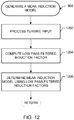
- a mean induction model is generated. For example, based on the input and/or information generated from the input (e.g., modeled turbine output parameters such as generator speed, power, rotor thrust, torque, blade pitch, etc.), a model describing a static or mean induction or inflow effect on turbine air flow is generated. As described above in connection with Equations 2 and 3, mean induction can be modeled using a model such as an actuator disk model to relate rotor average induction to thrust.
- a dynamic induction model is generated. For example, based on the input and/or information generated from the input (e.g., modeled turbine output parameters such as generator speed, power, rotor thrust, torque, blade pitch, etc.), a model describing a delayed or dynamic induction or inflow effect on turbine air flow is generated. As described above in connection with Equations 6, 7, and 8, dynamic induction can be modeled using a model such as an actuator disk model to relate rotor average induction to thrust.
- configuration information is evaluated to determine whether or not a mean correction factor is to be computed.
- the configuration and/or instruction for the wind estimation processor 530 is evaluated to determine whether or not the mean induction correction generator 650 is to be used to process the mean induction model and generate a mean induction correction factor.
- configuration information is evaluated to determine whether or not a dynamic correction factor is to be computed.
- the configuration and/or instruction for the wind estimation processor 530 is evaluated to determine whether or not the dynamic induction correction generator 660 is to be used to process the dynamic induction model and generate a dynamic induction correction factor.
- the mean induction correction factor is determined.
- the mean induction model from the mean induction model builder 630 is used alone or in conjunction with information from the model based processor 620 by the mean induction correction generator 650 to generate a mean induction corrector factor to be applied to a LIDAR wind speed estimate.
- Equations 4 and/or 5 illustrate how the mean induction model can be used to formulate a correction factor for mean induction with respect to a LIDAR estimate of wind speed (e.g., as part of a flow model).
- sensor information e.g., blade pitch angle, rotor speed, power output, torque, etc.
- model information can be used with a low-pass filter, estimated wind speed, rotor radius, air density, thrust coefficient, and/or estimated mean thrust, etc., to compute a mean induction correction factor based on Equations 2 and 3 to be applied per Equations 4 and 5.
- Mean induction can be deduced from thrust and/or other turbine parameter as a function of wind speed, for example.
- the dynamic induction correction factor is determined.
- the dynamic induction model from the dynamic induction model builder 640 is used alone or in conjunction with information from the model based processor 620 by the dynamic induction correction generator 660 to generate a dynamic induction corrector factor to be applied to a LIDAR wind speed estimate.
- Equations 9 and/or 10 illustrate how the dynamic induction model can be used to formulate a correction factor for dynamic induction with respect to the LIDAR estimate of wind speed (e.g., as part of a flow model).
- sensor information e.g., blade pitch angle, rotor speed, power output, torque, etc.
- model information can be used with a low-pass filter (e.g., to remove noise), thrust coefficient (e.g., computed from model-based thrust, etc.), rotor scaling constant, and/or wind speed scaling constant, etc., to compute a dynamic induction correction factor based on Equations 6-8 to be applied per Equations 9 and 10.
- Dynamic induction can be deduced from thrust and/or other turbine parameter as a function of wind speed, for example.
- the dynamic induction model can be integrated by the dynamic induction correction generator 640 to compute the delayed or dynamic induction correction factor.
- the mean and dynamic induction correction factors can be generated based on one or more simplifications of wind field behavior/characteristic. For example, an average induced flow over a radius r (e.g., taken alone and/or weighted according to a shape factor, etc.) and a low-pass filtered and/or time-averaged induced wind field (e.g., over a given period of time and/or for given wind turbine operating conditions, etc.) can be determined and used to affect a LIDAR estimate of wind speed with respect to the turbine 100.
- a radius r e.g., taken alone and/or weighted according to a shape factor, etc.
- a low-pass filtered and/or time-averaged induced wind field e.g., over a given period of time and/or for given wind turbine operating conditions, etc.
- information is evaluated to determine whether or not an initial wind speed estimate has been determined.
- the LIDAR wind estimator 610 can generate an initial wind estimate and/or an initial wind estimate can otherwise be input into the wind estimation processor 530.
- the mean and dynamic induction information e.g., mean and dynamic induction models and, available, mean and dynamic induction correction factors
- the initial wind speed estimate e.g., account for mean and dynamic induction effects in the LIDAR wind speed measurement to provide a more accurate estimate for feedforward turbine control, etc.
- the LIDAR wind speed estimator 670 estimates wind speed based on an output from the LIDAR wind estimator 610 adjusted by the mean induction correction factor and the dynamic induction correction factor. For example, Equations 5 and 10 can be applied to adjust the LIDAR estimate according to the mean and dynamic induction factors.
- the LIDAR wind speed estimate can be based on an initial wind parameter estimate (e.g., from the LIDAR wind estimator 610) adjusted by calculated mean wind speed variation.
- a wind speed estimate is calculated.
- the LIDAR wind speed estimator 670 uses the mean induction model and the dynamic induction model (e.g., provided by the mean induction model builder 630 and the dynamic induction model builder 640, etc.) in conjunction with the LIDAR sensor data 510 to determine and correct an estimate of wind speed, etc., to be provided to the wind turbine controller 540.
- the LIDAR wind speed estimator 670 can utilize mean and dynamic induction information to correct an initial wind estimate and/or to generate a more accurate wind estimate from LIDAR sensor data 510 and turbine operating data 520.
- a control signal for the wind turbine 100 is generated based on the wind estimate information.
- the LIDAR wind speed estimator 670 outputs a rotor effective wind speed for use by the wind turbine controller 540 to control operation of the wind turbine 100.
- the wind speed estimator 670 can also output one or more other wind turbine control parameters including rotor effective wind direction, rotor effective wind shear, etc., to be provided to the wind turbine controller 540.
- both static and dynamic deceleration caused by wind can be modeled and accounted for to better control the turbine 100, for example.
- the turbine control parameters are determined a priori, rather than a posteriori to provide feedforward control of the wind turbine 100 accounting for both mean and dynamic induction effects.
- feedforward control an incoming wind signal is estimated in advance for real time and/or substantially real time (e.g., accounting for some processing and/or transmission delay) adjustment of turbine 100 control. Processing after the fact can result in lost benefit from outdated information.
- Feedforward induction processing and correction apriori can correct for induction effect(s) and improve (e.g., correct and/or otherwise increase) preview time for improved accuracy of wind measurement and turbine control, for example.
- Apriori induction correction using model(s) for induction differs from cross-correlation methods for wind speed adjustment.
- a cross-correlation method between observed lidar estimated wind speed and turbine operating data such as wind speed can establish a) a correlation coefficient, which measures "goodness" or appropriateness of a comparison between the lidar estimate and turbine operating data; and b) a correlation time delay between the lidar estimate and turbine operating data.
- the correlation coefficient and correlation time delay can be used to form a correction that can be applied onto the lidar scale or a time delay to compensate for an observed difference.
- cross-correlation methods implies an a-posteriori approach with the use of an analysis time window in which different correlations are computed and averaged. Such time windows can range from several minutes up to 10s. A long time window will increase the statistical accuracy of the cross-correlation analysis, and a short time window will result in a statistically uncertain estimate.
- a posteriori cross-correlation method using past data is of less value than a model based induction method in order to derive a correction for a variable (e.g., wind speed, wind direction, wind shear, etc.) to be used for feed-forward control.
- a variable e.g., wind speed, wind direction, wind shear, etc.
- dynamic effects such as a pitch of blades
- this induction effect can be detected instantaneously with an induction model that knows blade pitch.
- this effect does not start to influence parameters of a cross-correlation method until a time period has lapsed, typically half of the averaging time window, which can introduce an unwanted and uncontrolled delay in any correction applied using such cross correlation method.
- a correlation method can adjust preview time
- the model-based approach can correct LIDAR data values, thereby providing more accurate data as well as corrected preview time and improved turbine operating control and performance.
- a LIDAR beam from a LIDAR sensor 420 (e.g., a pulsed or continuous wave Doppler LIDAR sensor, etc.) mounted on or near the turbine 100 is used to scan points upwind of the turbine 100.
- a LIDAR sensor 420 e.g., a pulsed or continuous wave Doppler LIDAR sensor, etc.
- scanned points are mapped to a reference coordinate system.
- a reference coordinate system e.g., x-y coordinate, x-y-z coordinate, polar coordinate, etc.
- a speed or velocity estimate is determined for the wind based on the mapped points.
- the LIDAR wind estimator 610 can process a sequence of mapped points over time to measure distance traveled per unit of time in the reference coordinate system. Such distance over time can be used to determine a wind speed estimate (and velocity if direction is analyzed based on the coordinates as well).
- turbine sensor measurement is received.
- rotor aerodynamic thrust can be estimated from turbine operating data.
- a value of aerodynamic thrust, T can be derived from strain gauge measurements located in the tower 116 and/or blades 114 of the example turbine 100.
- a model-based estimate is formed for a turbine operating parameter.
- the model based processor 620 can generate a model based estimation of thrust and/or other parameter based on measured and/or modeled rotor speed, generator torque, blade pitch angle, etc. (see, e.g., Equation 1 above).
- the turbine sensor measurement and model-based estimate are combined to form a model of the turbine 100.
- the model based processor 620 uses the input information 520 and/or other information regarding turbine 100 components, operation, operating conditions, etc., to estimate/model turbine output parameter(s), for example.
- the model-based processor 620 processes turbine operating data 520 to estimate turbine output parameters such as generator speed, power, rotor thrust, torque, blade pitch, etc.
- the model-based processor 620 provides accurate turbine condition information relying on models and/or sensed (e.g., measured) parameters.
- turbine input e.g., turbine operating data 520
- turbine operating data can be used to form an aerodynamic model, such as an actuator disk model and/or other model based on a blade element momentum theory, etc., to estimate, at a given time, induction under quasi-steady flow assumption.
- Average (e.g., low pass filtered) estimates can be determined for the thrust coefficient C T .
- the averaging time can range from 20 seconds to several minutes, which dictates a type of parameter(s) used for filtering.
- a low pass filtered variable is generated for one or more variables via a low pass filtering of rotor estimated wind information.
- a low pass filtered thrust can be generated from wind thrust observations/measurements.
- blade pitch angle can be low pass filtered.
- a mean induction model can be determined from the low pass filtered induction factors. For example, as shown in Equation 2, a mean induction model (e.g., an actuator disk model) can be estimated from low pass filtered thrust. For example, the actuator disk model can be used to relate a rotor average induction factor to thrust C T per Equations 2 and 3.
- the mean induction model represents a wind field model accounting for a mean induction effect, for example.
- the LIDAR wind speed estimator 670 and/or the mean induction correction generator 650 uses the mean induction model to generate a mean induction corrector factor to be applied to a LIDAR estimate.
- Equations 4 and/or 5, described above illustrate how the mean induction model can be used to formulate a correction factor for mean induction with respect to a LIDAR estimate of wind speed (e.g., as part of a flow model).
- sensor information e.g., blade pitch angle, rotor speed, power output, torque, etc.
- model information can be used with a low-pass filter, estimated wind speed, rotor radius, air density, thrust coefficient, and/or estimated mean thrust, etc., to compute a mean induction correction factor based on Equations 2 and 3 to be applied per Equations 4 and 5.
- Mean induction can be deduced from thrust and/or other turbine parameter as a function of wind speed, for example.
- turbine input e.g., turbine operating data 520
- turbine operating data can be used to form an aerodynamic model, such as an actuator disk model and/or other model based on a blade element or rotor momentum theory, etc., to estimate, at a given time, induction under quasi-steady flow assumption.
- an instantaneous or quasi-steady induction estimate is computed. For example, as described above in connection with Equations 6 and 7, C T can be used to estimate an instantaneous or quasi-steady induction.
- a delayed induction estimate is computed. For example, as described above in connection with Equation 8, a dynamic induction effect after an elapsed time delay can be determined to account for a wake convecting downstream.
- both instantaneous and delayed induction estimates are used to determine a dynamic induction model.
- instantaneous or "quasi-steady" induction effect and delayed wake induction effect can be used to form a more complete dynamic induction model to correct a LIDAR wind parameter estimate.
- the dynamic induction model represents a wind field model accounting for a dynamic induction effect, for example.
- the LIDAR wind speed estimator 670 and/or the dynamic induction correction generator 650 uses the dynamic induction model to generate a dynamic induction corrector factor to be applied to a LIDAR estimate.
- Equations 9 and/or 10, described above illustrate how the dynamic induction model can be used to formulate a correction factor for dynamic induction with respect to the LIDAR estimate of wind speed (e.g., as part of a flow model).
- sensor information e.g., blade pitch angle, rotor speed, power output, torque, etc.
- model information can be used with a low-pass filter (e.g., to remove noise), thrust coefficient (e.g., computed from model-based thrust, etc.), rotor scaling constant, and/or wind speed scaling constant, etc., to compute a dynamic induction correction factor based on Equations 6-8 to be applied per Equations 9 and 10.
- Dynamic induction can be deduced from thrust and/or other turbine parameter as a function of wind speed, for example.
- the dynamic induction model can be integrated by the dynamic induction correction generator 640 to compute the delayed or dynamic induction correction factor.
- certain examples provide apriori induction correction for wind turbine operating conditions with respect to LIDAR wind data based on turbine operating data. Certain examples enable improved feedforward turbine control using models to correct LIDAR data, rather than side-effects of the LIDAR data, which results in more accurate data, improved preview time, and better turbine operation.
- FIG. 14 is a block diagram of an example processor platform 1400 capable of executing the instructions of FIG. 9-13 to implement the systems of FIGS. 1-8 .
- the processor platform 1400 can be, for example, a server, a personal computer, a mobile device (e.g., a cell phone, a smart phone, a tablet such as an iPad TM ), a personal digital assistant (PDA), an Internet appliance, a DVD player, a CD player, a digital video recorder, a Blu-ray player, a gaming console, a personal video recorder, a set top box, or any other type of computing device.
- a mobile device e.g., a cell phone, a smart phone, a tablet such as an iPad TM
- PDA personal digital assistant
- an Internet appliance e.g., a DVD player, a CD player, a digital video recorder, a Blu-ray player, a gaming console, a personal video recorder, a set top box, or any other type of computing device.
- the processor platform 1400 of the illustrated example includes a processor 1412.
- the processor 1412 of the illustrated example is hardware.
- the processor 1412 can be implemented by one or more integrated circuits, logic circuits, microprocessors or controllers from any desired family or manufacturer.
- the processor 1412 of the illustrated example includes a local memory 1413 (e.g., a cache).
- the processor 1412 of the illustrated example is in communication with a main memory including a volatile memory 1414 and a non-volatile memory 1416 via a bus 1418.
- the volatile memory 1414 may be implemented by Synchronous Dynamic Random Access Memory (SDRAM), Dynamic Random Access Memory (DRAM), RAMBUS Dynamic Random Access Memory (RDRAM) and/or any other type of random access memory device.
- the non-volatile memory 1416 may be implemented by flash memory and/or any other desired type of memory device. Access to the main memory 1414, 1416 is controlled by a memory controller.
- the processor platform 1400 of the illustrated example also includes an interface circuit 1420.
- the interface circuit 1420 may be implemented by any type of interface standard, such as an Ethernet interface, a universal serial bus (USB), and/or a peripheral component interconnect (PCI) express interface.
- one or more input devices 1422 are connected to the interface circuit 1420.
- the input device(s) 1422 permit(s) a user to enter data and commands into the processor 1412.
- the input device(s) 1422 can be implemented by, for example, an audio sensor, a microphone, a keyboard, a button, a mouse, a touchscreen, a track-pad, a trackball, isopoint and/or a voice recognition system.
- One or more output devices 1424 are also connected to the interface circuit 1420 of the illustrated example.
- the output devices 1424 can be implemented, for example, by display devices (e.g., a light emitting diode (LED), an organic light emitting diode (OLED), a liquid crystal display, a cathode ray tube display (CRT), a touchscreen, a tactile output device).
- the interface circuit 1420 of the illustrated example thus, typically includes a graphics driver card, a graphics driver chip or a graphics driver processor.
- the interface circuit 1420 of the illustrated example also includes a communication device such as a transmitter, a receiver, a transceiver, a modem and/or network interface card to facilitate exchange of data with external machines (e.g., computing devices of any kind) via a network 1426 (e.g., an Ethernet connection, a digital subscriber line (DSL), a telephone line, coaxial cable, a cellular telephone system, etc.).
- a communication device such as a transmitter, a receiver, a transceiver, a modem and/or network interface card to facilitate exchange of data with external machines (e.g., computing devices of any kind) via a network 1426 (e.g., an Ethernet connection, a digital subscriber line (DSL), a telephone line, coaxial cable, a cellular telephone system, etc.).
- DSL digital subscriber line
- the processor platform 1400 of the illustrated example also includes one or more mass storage devices 1428 for storing software and/or data.
- mass storage devices 1428 include floppy disk drives, hard drive disks, compact disk drives, Blu-ray disk drives, RAID systems, and digital versatile disk (DVD) drives.
- the coded instructions 1432 of FIGS. 9-13 may be stored in the mass storage device 1428, in the volatile memory 1414, in the non-volatile memory 1416, and/or on a removable tangible computer readable storage medium such as a CD or DVD.
Landscapes
- Engineering & Computer Science (AREA)
- Physics & Mathematics (AREA)
- Mechanical Engineering (AREA)
- General Engineering & Computer Science (AREA)
- Sustainable Development (AREA)
- Sustainable Energy (AREA)
- Chemical & Material Sciences (AREA)
- Combustion & Propulsion (AREA)
- Life Sciences & Earth Sciences (AREA)
- Electromagnetism (AREA)
- Computer Networks & Wireless Communication (AREA)
- General Physics & Mathematics (AREA)
- Radar, Positioning & Navigation (AREA)
- Remote Sensing (AREA)
- Fluid Mechanics (AREA)
- Wind Motors (AREA)
Applications Claiming Priority (1)
| Application Number | Priority Date | Filing Date | Title |
|---|---|---|---|
| US15/208,723 US10539116B2 (en) | 2016-07-13 | 2016-07-13 | Systems and methods to correct induction for LIDAR-assisted wind turbine control |
Publications (2)
| Publication Number | Publication Date |
|---|---|
| EP3273055A1 true EP3273055A1 (fr) | 2018-01-24 |
| EP3273055B1 EP3273055B1 (fr) | 2021-10-20 |
Family
ID=59313019
Family Applications (1)
| Application Number | Title | Priority Date | Filing Date |
|---|---|---|---|
| EP17179934.9A Active EP3273055B1 (fr) | 2016-07-13 | 2017-07-06 | Systèmes et procédés de correction de l'induction pour commande de turbine éolienne assistée par lidar |
Country Status (4)
| Country | Link |
|---|---|
| US (1) | US10539116B2 (fr) |
| EP (1) | EP3273055B1 (fr) |
| DK (1) | DK3273055T3 (fr) |
| ES (1) | ES2904565T3 (fr) |
Cited By (4)
| Publication number | Priority date | Publication date | Assignee | Title |
|---|---|---|---|---|
| EP3712621A1 (fr) * | 2019-03-18 | 2020-09-23 | IFP Energies nouvelles | Procede de prediction de la vitesse du vent dans le plan du rotor pour une eolienne equipee d'un capteur de teledetection par laser |
| EP3862561A1 (fr) * | 2020-02-07 | 2021-08-11 | General Electric Company | Systèmes et procédés de commande d'éoliennes par apprentissage automatique continu |
| EP4027009A1 (fr) * | 2021-01-08 | 2022-07-13 | General Electric Renovables España S.L. | Contrôle de la poussée des éoliennes par détection active de la turbulence du vent |
| EP3978749A4 (fr) * | 2019-05-30 | 2022-08-10 | Beijing Goldwind Science & Creation Windpower Equipment Co. Ltd. | Procédé et appareil de commande prédictive pour ensemble générateur éolien, et système de commande |
Families Citing this family (20)
| Publication number | Priority date | Publication date | Assignee | Title |
|---|---|---|---|---|
| CN104314757B (zh) * | 2014-10-15 | 2017-03-29 | 国电联合动力技术有限公司 | 一种风力发电机组偏航控制方法及系统 |
| US10519929B2 (en) * | 2016-11-09 | 2019-12-31 | General Electric Company | System and method for minimizing energy loss due to yaw untwist of a wind turbine |
| WO2018198225A1 (fr) * | 2017-04-26 | 2018-11-01 | 三菱電機株式会社 | Dispositif ai, dispositif radar laser et système de commande de parc éolien |
| US10774811B2 (en) | 2018-05-01 | 2020-09-15 | General Electric Company | Induction controlled wind turbine |
| US11080438B2 (en) * | 2018-05-30 | 2021-08-03 | International Business Machines Corporation | Building-information management system with directional wind propagation and diffusion |
| DE102018113706A1 (de) * | 2018-06-08 | 2019-12-12 | Wobben Properties Gmbh | Verfahren zum Betreiben einer Windenergieanlage, Windenergieanlage und Windpark |
| FR3088434B1 (fr) * | 2018-11-12 | 2020-11-13 | Ifp Energies Now | Procede de determination d’un facteur d’induction pour une eolienne equipee d’un capteur de teledetection par laser |
| EP3734063B1 (fr) * | 2019-04-30 | 2023-03-01 | Wobben Properties GmbH | Procédé de commande d'une éolienne |
| DE102019116050A1 (de) | 2019-06-13 | 2020-12-17 | Wobben Properties Gmbh | Verfahren und Windenergieanlage zum Erfassen einer Windgeschwindigkeit |
| CN110410281B (zh) * | 2019-07-15 | 2023-11-03 | 湖南科技大学 | 一种风电机组真实来流风速的测量方法和装置 |
| US11556000B1 (en) | 2019-08-22 | 2023-01-17 | Red Creamery Llc | Distally-actuated scanning mirror |
| US11629694B2 (en) * | 2019-10-22 | 2023-04-18 | General Electric Company | Wind turbine model based control and estimation with accurate online models |
| CN112855438B (zh) * | 2019-11-28 | 2023-03-28 | 北京国电思达科技有限公司 | 一种风电机组偏航对风动态补偿的方法 |
| EP3896277A1 (fr) * | 2020-04-15 | 2021-10-20 | Siemens Gamesa Renewable Energy A/S | Procédé et dispositif de commande d'un parc éolien |
| FR3115115B1 (fr) * | 2020-10-14 | 2022-10-14 | Ifp Energies Now | Procédé de détermination d’un facteur d’induction entre un plan de mesure et le plan du rotor d’une éolienne |
| FR3116123B1 (fr) * | 2020-11-06 | 2022-10-14 | Ifp Energies Now | Procédé de détermination de la vitesse du vent dans le plan du rotor d’une éolienne |
| CN112782789B (zh) * | 2020-12-25 | 2022-12-16 | 济南市气象局 | 一种台风移动的预测方法和装置 |
| CN113847199B (zh) * | 2021-10-27 | 2023-05-09 | 中国华能集团清洁能源技术研究院有限公司 | 一种基于机载雷达在线偏航系统的偏航优化控制方法 |
| CN114352474B (zh) * | 2022-01-28 | 2023-05-02 | 中国华能集团清洁能源技术研究院有限公司 | 基于激光雷达测风的风电机组一次调频控制方法及设备 |
| CN116557222B (zh) * | 2022-01-29 | 2024-05-03 | 金风科技股份有限公司 | 估计风力涡轮机转子处风速的方法及装置 |
Citations (2)
| Publication number | Priority date | Publication date | Assignee | Title |
|---|---|---|---|---|
| GB2476507A (en) * | 2009-12-23 | 2011-06-29 | Vestas Wind Sys As | Method And Apparatus For Protecting Wind Turbines From Gust Damage |
| US20130094961A1 (en) * | 2011-10-14 | 2013-04-18 | Ian Couchman | Estimation of wind properties using a light detection and ranging device |
Family Cites Families (114)
| Publication number | Priority date | Publication date | Assignee | Title |
|---|---|---|---|---|
| US12003A (en) * | 1854-11-28 | Pianofokte-action | ||
| US4298313A (en) | 1979-06-18 | 1981-11-03 | Hohenemser Kurt H | Horizontal axis wind generator having adaptive cyclic pitch control |
| US4420692A (en) | 1982-04-02 | 1983-12-13 | United Technologies Corporation | Motion responsive wind turbine tower damping |
| US5048285A (en) | 1990-03-26 | 1991-09-17 | Untied Technologies Corporation | Control system for gas turbine engines providing extended engine life |
| US5359888A (en) | 1993-02-16 | 1994-11-01 | The B. F. Goodrich Company | Air turbulence and wind shear sensor |
| EP0970308B1 (fr) | 1997-03-26 | 2003-05-21 | Forskningscenter Riso | Eolienne comportant un systeme servant a mesurer la vitesse du vent |
| DE19731918B4 (de) | 1997-07-25 | 2005-12-22 | Wobben, Aloys, Dipl.-Ing. | Windenergieanlage |
| DE10137272A1 (de) | 2001-07-31 | 2003-02-27 | Aloys Wobben | Frühwarnsystem für Windenergieanlagen |
| CA2426711C (fr) | 2002-05-02 | 2009-11-17 | General Electric Company | Centrale eolienne, mecanisme de commande de centrale eolienne et methode d'exploitation d'une centrale eolienne |
| GB2398841A (en) | 2003-02-28 | 2004-09-01 | Qinetiq Ltd | Wind turbine control having a Lidar wind speed measurement apparatus |
| JP4102278B2 (ja) | 2003-03-19 | 2008-06-18 | 三菱電機株式会社 | 風力発電システム |
| ES2619198T3 (es) | 2003-04-09 | 2017-06-23 | General Electric Company | Parque eólico y procedimiento de operación del mismo |
| JP4589633B2 (ja) | 2004-01-29 | 2010-12-01 | 富士重工業株式会社 | 水平軸風車及び水平軸風車の制御方法 |
| US7203554B2 (en) | 2004-03-16 | 2007-04-10 | United Technologies Corporation | Model predictive controller with life extending control |
| NO20041208L (no) | 2004-03-22 | 2005-09-23 | Sway As | Fremgangsmate for reduskjon av aksialkraftvariasjoner for rotor samt retningskontroll for vindkraft med aktiv pitchregulering |
| GB0411097D0 (en) | 2004-05-19 | 2004-06-23 | Qinetiq Ltd | Laser radar device and method |
| US7175389B2 (en) | 2004-06-30 | 2007-02-13 | General Electric Company | Methods and apparatus for reducing peak wind turbine loads |
| US8500624B2 (en) | 2004-10-25 | 2013-08-06 | Boston Scientific Scimed, Inc. | Systems and methods for sling delivery and placement |
| CN102536658B (zh) | 2005-05-31 | 2014-10-01 | 株式会社日立制作所 | 水平轴风车 |
| DE102005045516A1 (de) * | 2005-09-22 | 2007-03-29 | Daubner & Stommel GbR Bau-Werk-Planung (vertretungsberechtigter Gesellschafter: Matthias Stommel, 27777 Ganderkesee) | Verfahren zur Anpassung einer Windenergieanlage an gegebene Windverhältnisse |
| US7342323B2 (en) | 2005-09-30 | 2008-03-11 | General Electric Company | System and method for upwind speed based control of a wind turbine |
| US20070124025A1 (en) | 2005-11-29 | 2007-05-31 | General Electric Company | Windpark turbine control system and method for wind condition estimation and performance optimization |
| JP4698418B2 (ja) | 2005-12-28 | 2011-06-08 | 株式会社エヌ・ティ・ティ・ドコモ | 通信システム、通信装置、通信方法及びプログラム |
| US7379169B1 (en) | 2006-12-08 | 2008-05-27 | General Electric Company | System and method for integrated measurement using optical sensors |
| JP5022102B2 (ja) | 2007-05-25 | 2012-09-12 | 三菱重工業株式会社 | 風力発電装置、風力発電システムおよび風力発電装置の発電制御方法 |
| EP2017468A1 (fr) | 2007-07-20 | 2009-01-21 | Siemens Aktiengesellschaft | Procédé pour le contrôle de lacet d'éolienne |
| US7950901B2 (en) | 2007-08-13 | 2011-05-31 | General Electric Company | System and method for loads reduction in a horizontal-axis wind turbine using upwind information |
| EP2229611A1 (fr) | 2007-11-26 | 2010-09-22 | Vestas Wind Systems A/S | Méthode et système d'enregistrement d'événements relatifs aux éoliennes d'un système d'énergie éolienne |
| WO2009068036A2 (fr) | 2007-11-30 | 2009-06-04 | Vestas Wind Systems A/S | Éolienne, procédé pour commander une éolienne et utilisation de celle-ci |
| US7999406B2 (en) | 2008-02-29 | 2011-08-16 | General Electric Company | Wind turbine plant high wind derating control |
| EP2110551B2 (fr) | 2008-04-15 | 2019-02-27 | Siemens Aktiengesellschaft | Procédé et appareil pour le contrôle d'une éolienne selon les prédictions |
| US7942629B2 (en) | 2008-04-22 | 2011-05-17 | General Electric Company | Systems and methods involving wind turbine towers for power applications |
| US8267654B2 (en) | 2008-05-16 | 2012-09-18 | Frontier Wind, Llc | Wind turbine with gust compensating air deflector |
| US8192161B2 (en) | 2008-05-16 | 2012-06-05 | Frontier Wind, Llc. | Wind turbine with deployable air deflectors |
| US8793027B2 (en) | 2008-06-30 | 2014-07-29 | Vestas Wind Systems A/S | Power curtailment of wind turbines |
| NZ590221A (en) | 2008-06-30 | 2013-05-31 | Vestas Wind Sys As | Controlling instantaneous power output from a wind power plant based on a determined upper limit power output |
| JP5244502B2 (ja) | 2008-08-25 | 2013-07-24 | 三菱重工業株式会社 | 風車の運転制限調整装置及び方法並びにプログラム |
| JP5199828B2 (ja) | 2008-10-29 | 2013-05-15 | 三菱重工業株式会社 | 風力発電装置及びその制御方法 |
| US20100140936A1 (en) | 2008-12-23 | 2010-06-10 | General Electric Company | Wind turbine with gps load control |
| JP4995209B2 (ja) | 2009-01-05 | 2012-08-08 | 三菱重工業株式会社 | 風力発電装置及び風力発電装置の風向推定方法 |
| WO2010086688A1 (fr) | 2009-01-28 | 2010-08-05 | Clipper Windpower, Inc. | Atténuation de charge dans une éolienne |
| US20100195089A1 (en) | 2009-01-30 | 2010-08-05 | General Electric Company | Wind velocity measurement system and method |
| NL2002476C2 (en) | 2009-02-02 | 2010-08-03 | Univ Delft Tech | WIND TURBINE. |
| GB2468693A (en) | 2009-03-18 | 2010-09-22 | Vestas Wind Sys As | Wind turbine blade control |
| EP2251543B1 (fr) | 2009-05-14 | 2016-12-07 | ALSTOM Renewable Technologies | Procédé et système pour la prédiction de l'événement d'une rafale de vent sur une éolienne |
| JP5439030B2 (ja) | 2009-05-18 | 2014-03-12 | 信越化学工業株式会社 | ネガ型レジスト組成物の検査方法及び調製方法 |
| ES2393046T3 (es) | 2009-06-24 | 2012-12-18 | Siemens Aktiengesellschaft | Disposición y método para controlar la guiñada de una turbina eólica |
| EP2267305B1 (fr) | 2009-06-24 | 2016-01-13 | Vestas Wind Systems A/S | Procédé et système pour contrôler le fonctionnement d'une éolienne |
| EP2467598A1 (fr) | 2009-08-21 | 2012-06-27 | Catch The Wind, Inc. | Prévision du vent et de l'énergie utilisant un détecteur de vent à distance à lidar |
| US8538735B2 (en) | 2009-09-08 | 2013-09-17 | Wm. Stevens Taber, Jr. | Use of devices for measuring fluid movement conditions at a distance to reduce the design and manufacturing cost of moving-fluid-driven working devices |
| CN102667495A (zh) | 2009-09-28 | 2012-09-12 | 喷特路姆科技有限公司 | 用于远程风感测的方法、装置和系统 |
| US8025476B2 (en) | 2009-09-30 | 2011-09-27 | General Electric Company | System and methods for controlling a wind turbine |
| US8390791B2 (en) | 2009-11-30 | 2013-03-05 | General Electric Company | Light detection and ranging system |
| GB2476316B (en) | 2009-12-21 | 2014-07-16 | Vestas Wind Sys As | A wind turbine having a control method and controller for predictive control of a wind turbine generator |
| GB2476506A (en) | 2009-12-23 | 2011-06-29 | Vestas Wind Sys As | Method And Apparatus Protecting Wind Turbines From Low Cycle Fatigue Damage |
| JP5101689B2 (ja) | 2010-01-27 | 2012-12-19 | 三菱重工業株式会社 | 風力発電装置及び風力発電装置のヨー旋回制御方法 |
| GB2477529A (en) | 2010-02-04 | 2011-08-10 | Vestas Wind Sys As | A wind turbine optical wind sensor for determining wind speed and direction |
| CA2788799A1 (fr) | 2010-02-05 | 2011-08-11 | Catch the Wind, Inc. | Collecte de donnees haute densite de vitesse du vent pour turbine eolienne |
| EP2535572A1 (fr) | 2010-02-08 | 2012-12-19 | Mitsubishi Heavy Industries, Ltd. | Aérogénérateur et procédé de rotation de nacelle |
| GB2479415A (en) | 2010-04-09 | 2011-10-12 | Vestas Wind Sys As | Wind Turbine Independent Blade Control Outside The Rated Output |
| GB201013239D0 (en) | 2010-06-04 | 2010-09-22 | Vestas Wind Sys As | An improved wind turbine doppler anemometer |
| GB2481461A (en) | 2010-06-21 | 2011-12-28 | Vestas Wind Sys As | Control of a downstream wind turbine in a wind park by sensing the wake turbulence of an upstream turbine |
| GB2481397B (en) | 2010-06-21 | 2013-04-03 | Vestas Wind Sys As | Estimation of wind conditions at a wind turbine |
| GB2481789A (en) | 2010-06-30 | 2012-01-11 | Vestas Wind Sys As | Reducing yaw error in wind turbines |
| CN102332615A (zh) | 2010-07-13 | 2012-01-25 | 库巴特克公司 | 电池修复方法和设备 |
| ES2550768T3 (es) | 2010-08-12 | 2015-11-12 | Vestas Wind Systems A/S | Control de una central eólica |
| US8202049B2 (en) | 2010-08-31 | 2012-06-19 | Catch the Wind, Inc. | Independent blade pitch control |
| NL2005400C2 (en) | 2010-09-27 | 2012-03-28 | Stichting Energie | Method and system for wind gust detection in a wind turbine. |
| GB2485340A (en) | 2010-11-02 | 2012-05-16 | Vestas Wind Sys As | A wind turbine comprising rotor and tower bending sensors |
| US8150641B2 (en) | 2010-12-06 | 2012-04-03 | General Electric Company | System, device, and method for estimating possible power output of wind turbines |
| US8704390B2 (en) | 2010-12-07 | 2014-04-22 | Vestas Wind Systems A/S | Dynamic adjustment of power plant output based on electrical grid characteristics |
| US8178989B2 (en) | 2010-12-15 | 2012-05-15 | General Electric Company | System and methods for adjusting a yaw angle of a wind turbine |
| US8076789B2 (en) | 2010-12-21 | 2011-12-13 | General Electric Company | System and method for controlling wind turbine power output |
| US8915709B2 (en) | 2010-12-30 | 2014-12-23 | Vestas Wind Systems A/S | Optical angle of attack detector based on light detection and ranging (LIDAR) for control of an aerodynamic surface |
| GB2487715A (en) | 2011-01-18 | 2012-08-08 | Vestas Wind Sys As | Method and apparatus for protecting wind turbines from extreme wind direction changes |
| BR112013018853B1 (pt) | 2011-01-31 | 2021-03-16 | General Electric Company | método de operação de uma turbina eólica, sistema de controle de turbina eólica para o uso com uma turbina eólica e sistema de turbina eólica |
| CN103562709A (zh) | 2011-04-28 | 2014-02-05 | 维斯塔斯风力系统集团公司 | 用于保护风力涡轮机不受极端事件影响的方法和装置 |
| CN103635812B (zh) | 2011-05-04 | 2017-03-01 | 维斯塔斯风力系统集团公司 | 风力涡轮机光学风传感器 |
| US9822763B2 (en) | 2011-05-06 | 2017-11-21 | Vestas Wind Systems A/S | Method and apparatus for protecting wind turbines from extreme events |
| CN102797634A (zh) | 2011-05-27 | 2012-11-28 | 通用电气公司 | 风力涡轮机及监测风力涡轮机参数的方法 |
| EP2538719B1 (fr) | 2011-06-24 | 2020-03-11 | Vodafone IP Licensing limited | Réseaux de télécommunication |
| IN2014DN00125A (fr) | 2011-06-30 | 2015-05-22 | Vestas Wind Sys As | |
| US20130003071A1 (en) | 2011-06-30 | 2013-01-03 | Catch the Wind, Inc. | System and Method of In Situ Wind Turbine Blade Monitoring |
| US9188104B2 (en) * | 2011-06-30 | 2015-11-17 | Vestas Wind Systems A/S | System and method for controlling power output from a wind turbine or wind power plant |
| WO2013023702A1 (fr) | 2011-08-18 | 2013-02-21 | Siemens Aktiengesellschaft | Procédé de régulation de la production électrique d'une turbine éolienne |
| EP2761713B1 (fr) | 2011-09-30 | 2018-04-18 | Vestas Wind Systems A/S | Dispositif de commande pour l'atténuation d'oscillations d'un réseau électrique |
| US20130088009A1 (en) | 2011-10-11 | 2013-04-11 | Clipper Windpower, Llc | Method to Prevent Over Torque of Yaw Drive Components in a Wind Turbine |
| WO2013057836A1 (fr) | 2011-10-21 | 2013-04-25 | 三菱重工業株式会社 | Dispositif générateur d'énergie éolienne et procédé de commande de la rotation en lacet du dispositif générateur d'énergie éolienne |
| ES2625057T3 (es) | 2011-11-21 | 2017-07-18 | Vestas Wind Systems A/S | Controlador de apagado para una turbina eólica y método de apagado de una turbina eólica |
| US9574548B2 (en) | 2011-12-08 | 2017-02-21 | Vestas Wind Systems A/S | Method and system for controlled shutdown of wind turbines |
| CN104160147B (zh) | 2011-12-21 | 2017-03-01 | 维斯塔斯风力系统集团公司 | 风力涡轮机叶片的除冰 |
| US8622698B2 (en) | 2011-12-22 | 2014-01-07 | Vestas Wind Systems A/S | Rotor-sector based control of wind turbines |
| EP2626551B1 (fr) | 2012-02-10 | 2019-06-12 | Vestas Wind Systems A/S | Procédé de commande d'une éolienne |
| US8669426B1 (en) | 2012-03-01 | 2014-03-11 | Pioneer Hi-Bred International Inc | Soybean variety XB37U12 |
| US20130259686A1 (en) | 2012-03-30 | 2013-10-03 | General Electric Company | System and method for controlling a wind turbine |
| ES2674157T3 (es) | 2012-06-06 | 2018-06-27 | Vestas Wind Systems A/S | Turbina eólica con un controlador de cargas |
| US9605654B2 (en) | 2012-07-24 | 2017-03-28 | General Electric Company | Wind turbine lifetime estimator |
| US9575177B2 (en) | 2012-07-27 | 2017-02-21 | Texas Tech University System | Apparatus and method for using radar to evaluate wind flow fields for wind energy applications |
| CN103573552B (zh) | 2012-08-02 | 2016-02-24 | 通用电气公司 | 风力涡轮机及其降低转子不平衡的控制方法 |
| EP2904264B1 (fr) | 2012-10-02 | 2018-02-28 | Vestas Wind Systems A/S | Système de commande d'éolienne |
| WO2014056633A1 (fr) | 2012-10-12 | 2014-04-17 | Siemens Aktiengesellschaft | Procédé et commande pour exploiter en continu une pluralité de machines génératrices d'énergie électrique pendant une situation de haute tension |
| US8912674B2 (en) | 2012-10-15 | 2014-12-16 | General Electric Company | System and method of selecting wind turbine generators in a wind park for change of output power |
| US9677540B2 (en) | 2012-11-29 | 2017-06-13 | General Electric Company | System and method for providing yaw backup to a wind farm |
| US8872372B2 (en) | 2012-11-30 | 2014-10-28 | General Electric Company | Method and systems for operating a wind turbine when recovering from a grid contingency event |
| EP2932093B1 (fr) | 2012-12-14 | 2018-10-31 | Vestas Wind Systems A/S | Procédé et agencement pour régulation rapide de la puissance |
| US9303626B2 (en) | 2012-12-18 | 2016-04-05 | General Electric Company | Control system and method for mitigating loads during yaw error on a wind turbine |
| CN103061980A (zh) | 2012-12-28 | 2013-04-24 | 东方电气集团东方汽轮机有限公司 | 基于激光测风雷达的风力发电机组的前馈控制系统及其控制方法 |
| US9562515B2 (en) | 2013-02-01 | 2017-02-07 | General Electric Company | Method and apparatus for wind turbine noise reduction |
| US9366230B2 (en) | 2013-03-14 | 2016-06-14 | General Electric Company | System and method for reducing loads acting on a wind turbine in response to transient wind conditions |
| DK2799711T3 (en) | 2013-05-03 | 2017-10-23 | Ge Renewable Tech Wind Bv | Method of operating a wind turbine |
| US9605558B2 (en) | 2013-08-20 | 2017-03-28 | General Electric Company | System and method for preventing excessive loading on a wind turbine |
| CN104454350B (zh) | 2013-09-23 | 2019-01-08 | 通用电气公司 | 风力涡轮机及其降低转子不平衡载荷的控制方法 |
| FR3013777B1 (fr) | 2013-11-25 | 2015-11-13 | IFP Energies Nouvelles | Procede de controle et de surveillance d'une eolienne au moyen d'une estimation de la vitesse du vent au moyen d'un capteur lidar |
| US10280897B2 (en) | 2015-12-10 | 2019-05-07 | General Electric Company | Methods and systems for controlling a wind turbine |
-
2016
- 2016-07-13 US US15/208,723 patent/US10539116B2/en active Active
-
2017
- 2017-07-06 DK DK17179934.9T patent/DK3273055T3/da active
- 2017-07-06 ES ES17179934T patent/ES2904565T3/es active Active
- 2017-07-06 EP EP17179934.9A patent/EP3273055B1/fr active Active
Patent Citations (2)
| Publication number | Priority date | Publication date | Assignee | Title |
|---|---|---|---|---|
| GB2476507A (en) * | 2009-12-23 | 2011-06-29 | Vestas Wind Sys As | Method And Apparatus For Protecting Wind Turbines From Gust Damage |
| US20130094961A1 (en) * | 2011-10-14 | 2013-04-18 | Ian Couchman | Estimation of wind properties using a light detection and ranging device |
Non-Patent Citations (1)
| Title |
|---|
| DUNNE FIONA ET AL: "Importance of lidar measurement timing accuracy for wind turbine control", 2015 AMERICAN CONTROL CONFERENCE (ACC), IEEE, 4 June 2014 (2014-06-04), pages 3716 - 3721, XP032621481, ISSN: 0743-1619, [retrieved on 20140717], DOI: 10.1109/ACC.2014.6859337 * |
Cited By (8)
| Publication number | Priority date | Publication date | Assignee | Title |
|---|---|---|---|---|
| EP3712621A1 (fr) * | 2019-03-18 | 2020-09-23 | IFP Energies nouvelles | Procede de prediction de la vitesse du vent dans le plan du rotor pour une eolienne equipee d'un capteur de teledetection par laser |
| FR3094093A1 (fr) * | 2019-03-18 | 2020-09-25 | IFP Energies Nouvelles | Procédé de prédiction de la vitesse du vent dans le plan du rotor pour une éolienne équipée d’un capteur de télédétection par Laser |
| US11105929B2 (en) | 2019-03-18 | 2021-08-31 | IFP Energies Nouvelles | Method for predicting wind speed in the rotor plane for a wind turbine equipped with a LiDAR sensor |
| EP3978749A4 (fr) * | 2019-05-30 | 2022-08-10 | Beijing Goldwind Science & Creation Windpower Equipment Co. Ltd. | Procédé et appareil de commande prédictive pour ensemble générateur éolien, et système de commande |
| US12098707B2 (en) | 2019-05-30 | 2024-09-24 | Beijing Goldwind Science & Creation Windpower Equipment Co., Ltd. | Feedforward control method, apparatus and control system for wind turbine |
| EP3862561A1 (fr) * | 2020-02-07 | 2021-08-11 | General Electric Company | Systèmes et procédés de commande d'éoliennes par apprentissage automatique continu |
| EP4027009A1 (fr) * | 2021-01-08 | 2022-07-13 | General Electric Renovables España S.L. | Contrôle de la poussée des éoliennes par détection active de la turbulence du vent |
| US11408396B2 (en) | 2021-01-08 | 2022-08-09 | General Electric Renovables Espana, S.L. | Thrust control for wind turbines using active sensing of wind turbulence |
Also Published As
| Publication number | Publication date |
|---|---|
| ES2904565T3 (es) | 2022-04-05 |
| DK3273055T3 (da) | 2022-01-17 |
| US20180017039A1 (en) | 2018-01-18 |
| EP3273055B1 (fr) | 2021-10-20 |
| US10539116B2 (en) | 2020-01-21 |
Similar Documents
| Publication | Publication Date | Title |
|---|---|---|
| EP3273055B1 (fr) | Systèmes et procédés de correction de l'induction pour commande de turbine éolienne assistée par lidar | |
| JP6001770B2 (ja) | 風力発電装置、および風力発電装置またはウィンドパークの制御方法 | |
| JP6625052B2 (ja) | タービンの流体速度場測定 | |
| CN109219782B (zh) | 用于控制动态系统的系统及方法 | |
| US9551322B2 (en) | Systems and methods for optimizing operation of a wind farm | |
| US9234506B2 (en) | Estimation of wind properties using a light detection and ranging device | |
| CN103890383B (zh) | 控制风力涡轮机的方法及相关系统 | |
| EP3023636A1 (fr) | Systemes et procedes pour optimiser le fonctionnement d'un parc eolien | |
| EP2581761B1 (fr) | Estimation des propriétés éoliennes au moyen d'un dispositif de détection de lumière et de télémétrie | |
| EP3276164A2 (fr) | Système et procédé de commande d'une éolienne | |
| EP3181897B1 (fr) | Fonctionnement d'une éolienne | |
| JP4626265B2 (ja) | 風力発電装置、風力発電装置の制御方法およびコンピュータプログラム | |
| EP3564524B1 (fr) | Éolienne commandée par induction | |
| TW201741561A (zh) | 風力渦輪機偏航失準估測 | |
| US11098698B2 (en) | System and method for auto-calibrating a load sensor system of a wind turbine | |
| EP3263890A1 (fr) | Procédés et systèmes de commande prédictive d'éoliennes | |
| CN109973330B (zh) | 一种上游风机尾流对下游风机影响情况的检测方法 | |
| JP2017506311A (ja) | エネルギー捕捉装置のエネルギー捕捉効率を向上させる方法及びシステム | |
| CN112114332A (zh) | 确定装备lidar传感器的风力涡轮机上游的风速垂直廓线的方法 | |
| CN111173686A (zh) | 确定配备有LiDAR传感器的风力涡轮机的感应因子的方法 | |
| CN113252938A (zh) | 确定风力发电机的转子平面中的风速的方法 | |
| CN114278510A (zh) | 借助LiDAR传感器来测定平均风速的方法 | |
| US20230026286A1 (en) | Method for computer-implemented monitoring of a wind turbine | |
| KR20150076737A (ko) | 풍력 터빈의 풍력 속도 추정 장치 및 그 풍력 속도 추정 방법 | |
| EP3343026A1 (fr) | Procédés et systèmes de commande d' une éolienne |
Legal Events
| Date | Code | Title | Description |
|---|---|---|---|
| PUAI | Public reference made under article 153(3) epc to a published international application that has entered the european phase |
Free format text: ORIGINAL CODE: 0009012 |
|
| STAA | Information on the status of an ep patent application or granted ep patent |
Free format text: STATUS: THE APPLICATION HAS BEEN PUBLISHED |
|
| AK | Designated contracting states |
Kind code of ref document: A1 Designated state(s): AL AT BE BG CH CY CZ DE DK EE ES FI FR GB GR HR HU IE IS IT LI LT LU LV MC MK MT NL NO PL PT RO RS SE SI SK SM TR |
|
| AX | Request for extension of the european patent |
Extension state: BA ME |
|
| STAA | Information on the status of an ep patent application or granted ep patent |
Free format text: STATUS: REQUEST FOR EXAMINATION WAS MADE |
|
| 17P | Request for examination filed |
Effective date: 20180724 |
|
| RBV | Designated contracting states (corrected) |
Designated state(s): AL AT BE BG CH CY CZ DE DK EE ES FI FR GB GR HR HU IE IS IT LI LT LU LV MC MK MT NL NO PL PT RO RS SE SI SK SM TR |
|
| GRAP | Despatch of communication of intention to grant a patent |
Free format text: ORIGINAL CODE: EPIDOSNIGR1 |
|
| STAA | Information on the status of an ep patent application or granted ep patent |
Free format text: STATUS: GRANT OF PATENT IS INTENDED |
|
| RIC1 | Information provided on ipc code assigned before grant |
Ipc: F03D 7/04 20060101ALI20210406BHEP Ipc: F03D 7/02 20060101AFI20210406BHEP |
|
| INTG | Intention to grant announced |
Effective date: 20210507 |
|
| GRAS | Grant fee paid |
Free format text: ORIGINAL CODE: EPIDOSNIGR3 |
|
| GRAA | (expected) grant |
Free format text: ORIGINAL CODE: 0009210 |
|
| STAA | Information on the status of an ep patent application or granted ep patent |
Free format text: STATUS: THE PATENT HAS BEEN GRANTED |
|
| AK | Designated contracting states |
Kind code of ref document: B1 Designated state(s): AL AT BE BG CH CY CZ DE DK EE ES FI FR GB GR HR HU IE IS IT LI LT LU LV MC MK MT NL NO PL PT RO RS SE SI SK SM TR |
|
| REG | Reference to a national code |
Ref country code: GB Ref legal event code: FG4D |
|
| REG | Reference to a national code |
Ref country code: CH Ref legal event code: EP |
|
| REG | Reference to a national code |
Ref country code: DE Ref legal event code: R096 Ref document number: 602017047797 Country of ref document: DE |
|
| REG | Reference to a national code |
Ref country code: IE Ref legal event code: FG4D |
|
| REG | Reference to a national code |
Ref country code: AT Ref legal event code: REF Ref document number: 1440156 Country of ref document: AT Kind code of ref document: T Effective date: 20211115 |
|
| REG | Reference to a national code |
Ref country code: DK Ref legal event code: T3 Effective date: 20220112 |
|
| REG | Reference to a national code |
Ref country code: LT Ref legal event code: MG9D |
|
| REG | Reference to a national code |
Ref country code: NL Ref legal event code: MP Effective date: 20211020 |
|
| REG | Reference to a national code |
Ref country code: AT Ref legal event code: MK05 Ref document number: 1440156 Country of ref document: AT Kind code of ref document: T Effective date: 20211020 |
|
| REG | Reference to a national code |
Ref country code: ES Ref legal event code: FG2A Ref document number: 2904565 Country of ref document: ES Kind code of ref document: T3 Effective date: 20220405 |
|
| PG25 | Lapsed in a contracting state [announced via postgrant information from national office to epo] |
Ref country code: RS Free format text: LAPSE BECAUSE OF FAILURE TO SUBMIT A TRANSLATION OF THE DESCRIPTION OR TO PAY THE FEE WITHIN THE PRESCRIBED TIME-LIMIT Effective date: 20211020 Ref country code: LT Free format text: LAPSE BECAUSE OF FAILURE TO SUBMIT A TRANSLATION OF THE DESCRIPTION OR TO PAY THE FEE WITHIN THE PRESCRIBED TIME-LIMIT Effective date: 20211020 Ref country code: FI Free format text: LAPSE BECAUSE OF FAILURE TO SUBMIT A TRANSLATION OF THE DESCRIPTION OR TO PAY THE FEE WITHIN THE PRESCRIBED TIME-LIMIT Effective date: 20211020 Ref country code: BG Free format text: LAPSE BECAUSE OF FAILURE TO SUBMIT A TRANSLATION OF THE DESCRIPTION OR TO PAY THE FEE WITHIN THE PRESCRIBED TIME-LIMIT Effective date: 20220120 Ref country code: AT Free format text: LAPSE BECAUSE OF FAILURE TO SUBMIT A TRANSLATION OF THE DESCRIPTION OR TO PAY THE FEE WITHIN THE PRESCRIBED TIME-LIMIT Effective date: 20211020 |
|
| PG25 | Lapsed in a contracting state [announced via postgrant information from national office to epo] |
Ref country code: IS Free format text: LAPSE BECAUSE OF FAILURE TO SUBMIT A TRANSLATION OF THE DESCRIPTION OR TO PAY THE FEE WITHIN THE PRESCRIBED TIME-LIMIT Effective date: 20220220 Ref country code: SE Free format text: LAPSE BECAUSE OF FAILURE TO SUBMIT A TRANSLATION OF THE DESCRIPTION OR TO PAY THE FEE WITHIN THE PRESCRIBED TIME-LIMIT Effective date: 20211020 Ref country code: PT Free format text: LAPSE BECAUSE OF FAILURE TO SUBMIT A TRANSLATION OF THE DESCRIPTION OR TO PAY THE FEE WITHIN THE PRESCRIBED TIME-LIMIT Effective date: 20220221 Ref country code: PL Free format text: LAPSE BECAUSE OF FAILURE TO SUBMIT A TRANSLATION OF THE DESCRIPTION OR TO PAY THE FEE WITHIN THE PRESCRIBED TIME-LIMIT Effective date: 20211020 Ref country code: NO Free format text: LAPSE BECAUSE OF FAILURE TO SUBMIT A TRANSLATION OF THE DESCRIPTION OR TO PAY THE FEE WITHIN THE PRESCRIBED TIME-LIMIT Effective date: 20220120 Ref country code: NL Free format text: LAPSE BECAUSE OF FAILURE TO SUBMIT A TRANSLATION OF THE DESCRIPTION OR TO PAY THE FEE WITHIN THE PRESCRIBED TIME-LIMIT Effective date: 20211020 Ref country code: LV Free format text: LAPSE BECAUSE OF FAILURE TO SUBMIT A TRANSLATION OF THE DESCRIPTION OR TO PAY THE FEE WITHIN THE PRESCRIBED TIME-LIMIT Effective date: 20211020 Ref country code: HR Free format text: LAPSE BECAUSE OF FAILURE TO SUBMIT A TRANSLATION OF THE DESCRIPTION OR TO PAY THE FEE WITHIN THE PRESCRIBED TIME-LIMIT Effective date: 20211020 Ref country code: GR Free format text: LAPSE BECAUSE OF FAILURE TO SUBMIT A TRANSLATION OF THE DESCRIPTION OR TO PAY THE FEE WITHIN THE PRESCRIBED TIME-LIMIT Effective date: 20220121 |
|
| REG | Reference to a national code |
Ref country code: DE Ref legal event code: R097 Ref document number: 602017047797 Country of ref document: DE |
|
| PG25 | Lapsed in a contracting state [announced via postgrant information from national office to epo] |
Ref country code: SM Free format text: LAPSE BECAUSE OF FAILURE TO SUBMIT A TRANSLATION OF THE DESCRIPTION OR TO PAY THE FEE WITHIN THE PRESCRIBED TIME-LIMIT Effective date: 20211020 Ref country code: SK Free format text: LAPSE BECAUSE OF FAILURE TO SUBMIT A TRANSLATION OF THE DESCRIPTION OR TO PAY THE FEE WITHIN THE PRESCRIBED TIME-LIMIT Effective date: 20211020 Ref country code: RO Free format text: LAPSE BECAUSE OF FAILURE TO SUBMIT A TRANSLATION OF THE DESCRIPTION OR TO PAY THE FEE WITHIN THE PRESCRIBED TIME-LIMIT Effective date: 20211020 Ref country code: EE Free format text: LAPSE BECAUSE OF FAILURE TO SUBMIT A TRANSLATION OF THE DESCRIPTION OR TO PAY THE FEE WITHIN THE PRESCRIBED TIME-LIMIT Effective date: 20211020 Ref country code: CZ Free format text: LAPSE BECAUSE OF FAILURE TO SUBMIT A TRANSLATION OF THE DESCRIPTION OR TO PAY THE FEE WITHIN THE PRESCRIBED TIME-LIMIT Effective date: 20211020 |
|
| PLBE | No opposition filed within time limit |
Free format text: ORIGINAL CODE: 0009261 |
|
| STAA | Information on the status of an ep patent application or granted ep patent |
Free format text: STATUS: NO OPPOSITION FILED WITHIN TIME LIMIT |
|
| 26N | No opposition filed |
Effective date: 20220721 |
|
| PG25 | Lapsed in a contracting state [announced via postgrant information from national office to epo] |
Ref country code: AL Free format text: LAPSE BECAUSE OF FAILURE TO SUBMIT A TRANSLATION OF THE DESCRIPTION OR TO PAY THE FEE WITHIN THE PRESCRIBED TIME-LIMIT Effective date: 20211020 |
|
| PG25 | Lapsed in a contracting state [announced via postgrant information from national office to epo] |
Ref country code: SI Free format text: LAPSE BECAUSE OF FAILURE TO SUBMIT A TRANSLATION OF THE DESCRIPTION OR TO PAY THE FEE WITHIN THE PRESCRIBED TIME-LIMIT Effective date: 20211020 |
|
| PG25 | Lapsed in a contracting state [announced via postgrant information from national office to epo] |
Ref country code: MC Free format text: LAPSE BECAUSE OF FAILURE TO SUBMIT A TRANSLATION OF THE DESCRIPTION OR TO PAY THE FEE WITHIN THE PRESCRIBED TIME-LIMIT Effective date: 20211020 |
|
| REG | Reference to a national code |
Ref country code: CH Ref legal event code: PL |
|
| GBPC | Gb: european patent ceased through non-payment of renewal fee |
Effective date: 20220706 |
|
| REG | Reference to a national code |
Ref country code: BE Ref legal event code: MM Effective date: 20220731 |
|
| PG25 | Lapsed in a contracting state [announced via postgrant information from national office to epo] |
Ref country code: LU Free format text: LAPSE BECAUSE OF NON-PAYMENT OF DUE FEES Effective date: 20220706 Ref country code: LI Free format text: LAPSE BECAUSE OF NON-PAYMENT OF DUE FEES Effective date: 20220731 Ref country code: FR Free format text: LAPSE BECAUSE OF NON-PAYMENT OF DUE FEES Effective date: 20220731 Ref country code: CH Free format text: LAPSE BECAUSE OF NON-PAYMENT OF DUE FEES Effective date: 20220731 |
|
| PG25 | Lapsed in a contracting state [announced via postgrant information from national office to epo] |
Ref country code: IT Free format text: LAPSE BECAUSE OF FAILURE TO SUBMIT A TRANSLATION OF THE DESCRIPTION OR TO PAY THE FEE WITHIN THE PRESCRIBED TIME-LIMIT Effective date: 20211020 Ref country code: GB Free format text: LAPSE BECAUSE OF NON-PAYMENT OF DUE FEES Effective date: 20220706 Ref country code: BE Free format text: LAPSE BECAUSE OF NON-PAYMENT OF DUE FEES Effective date: 20220731 |
|
| P01 | Opt-out of the competence of the unified patent court (upc) registered |
Effective date: 20230530 |
|
| PG25 | Lapsed in a contracting state [announced via postgrant information from national office to epo] |
Ref country code: IE Free format text: LAPSE BECAUSE OF NON-PAYMENT OF DUE FEES Effective date: 20220706 |
|
| PGFP | Annual fee paid to national office [announced via postgrant information from national office to epo] |
Ref country code: ES Payment date: 20230801 Year of fee payment: 7 |
|
| REG | Reference to a national code |
Ref country code: DE Ref legal event code: R082 Ref document number: 602017047797 Country of ref document: DE Representative=s name: ZIMMERMANN & PARTNER PATENTANWAELTE MBB, DE Ref legal event code: R082 Country of ref document: DE Ref country code: DE Ref legal event code: R081 Ref document number: 602017047797 Country of ref document: DE Owner name: GENERAL ELECTRIC RENOVABLES ESPANA, S.L., ES Free format text: FORMER OWNER: GENERAL ELECTRIC COMPANY, SCHENECTADY, NY, US |
|
| REG | Reference to a national code |
Ref country code: DE Ref legal event code: R082 Ref document number: 602017047797 Country of ref document: DE Representative=s name: ZIMMERMANN & PARTNER PATENTANWAELTE MBB, DE |
|
| PG25 | Lapsed in a contracting state [announced via postgrant information from national office to epo] |
Ref country code: HU Free format text: LAPSE BECAUSE OF FAILURE TO SUBMIT A TRANSLATION OF THE DESCRIPTION OR TO PAY THE FEE WITHIN THE PRESCRIBED TIME-LIMIT; INVALID AB INITIO Effective date: 20170706 |
|
| PG25 | Lapsed in a contracting state [announced via postgrant information from national office to epo] |
Ref country code: MK Free format text: LAPSE BECAUSE OF FAILURE TO SUBMIT A TRANSLATION OF THE DESCRIPTION OR TO PAY THE FEE WITHIN THE PRESCRIBED TIME-LIMIT Effective date: 20211020 Ref country code: CY Free format text: LAPSE BECAUSE OF FAILURE TO SUBMIT A TRANSLATION OF THE DESCRIPTION OR TO PAY THE FEE WITHIN THE PRESCRIBED TIME-LIMIT Effective date: 20211020 |
|
| PGFP | Annual fee paid to national office [announced via postgrant information from national office to epo] |
Ref country code: DK Payment date: 20240619 Year of fee payment: 8 |
|
| REG | Reference to a national code |
Ref country code: ES Ref legal event code: PC2A Owner name: GENERAL ELECTRIC RENOVABLES ESPANA S.L. Effective date: 20240809 |
|
| PG25 | Lapsed in a contracting state [announced via postgrant information from national office to epo] |
Ref country code: MT Free format text: LAPSE BECAUSE OF FAILURE TO SUBMIT A TRANSLATION OF THE DESCRIPTION OR TO PAY THE FEE WITHIN THE PRESCRIBED TIME-LIMIT Effective date: 20211020 |
|
| PGFP | Annual fee paid to national office [announced via postgrant information from national office to epo] |
Ref country code: DE Payment date: 20240619 Year of fee payment: 8 |