EP4027009A1 - Contrôle de la poussée des éoliennes par détection active de la turbulence du vent - Google Patents
Contrôle de la poussée des éoliennes par détection active de la turbulence du vent Download PDFInfo
- Publication number
- EP4027009A1 EP4027009A1 EP22150054.9A EP22150054A EP4027009A1 EP 4027009 A1 EP4027009 A1 EP 4027009A1 EP 22150054 A EP22150054 A EP 22150054A EP 4027009 A1 EP4027009 A1 EP 4027009A1
- Authority
- EP
- European Patent Office
- Prior art keywords
- wind speed
- wind
- rotor
- thrust
- turbulence
- Prior art date
- Legal status (The legal status is an assumption and is not a legal conclusion. Google has not performed a legal analysis and makes no representation as to the accuracy of the status listed.)
- Pending
Links
- 238000000034 method Methods 0.000 claims abstract description 63
- 238000009826 distribution Methods 0.000 claims abstract description 30
- 238000011144 upstream manufacturing Methods 0.000 claims abstract description 8
- 238000005259 measurement Methods 0.000 claims description 81
- 238000004364 calculation method Methods 0.000 claims description 15
- 238000012886 linear function Methods 0.000 claims description 8
- 238000004891 communication Methods 0.000 claims description 4
- 230000008569 process Effects 0.000 description 14
- IYLGZMTXKJYONK-ACLXAEORSA-N (12s,15r)-15-hydroxy-11,16-dioxo-15,20-dihydrosenecionan-12-yl acetate Chemical compound O1C(=O)[C@](CC)(O)C[C@@H](C)[C@](C)(OC(C)=O)C(=O)OCC2=CCN3[C@H]2[C@H]1CC3 IYLGZMTXKJYONK-ACLXAEORSA-N 0.000 description 10
- IYLGZMTXKJYONK-UHFFFAOYSA-N ruwenine Natural products O1C(=O)C(CC)(O)CC(C)C(C)(OC(C)=O)C(=O)OCC2=CCN3C2C1CC3 IYLGZMTXKJYONK-UHFFFAOYSA-N 0.000 description 10
- 230000006870 function Effects 0.000 description 9
- 230000000694 effects Effects 0.000 description 5
- 238000005452 bending Methods 0.000 description 4
- 238000004519 manufacturing process Methods 0.000 description 4
- 238000001514 detection method Methods 0.000 description 2
- 230000005611 electricity Effects 0.000 description 2
- 238000000605 extraction Methods 0.000 description 2
- 238000012986 modification Methods 0.000 description 2
- 230000004048 modification Effects 0.000 description 2
- 238000004458 analytical method Methods 0.000 description 1
- 230000009286 beneficial effect Effects 0.000 description 1
- 238000005094 computer simulation Methods 0.000 description 1
- 238000011217 control strategy Methods 0.000 description 1
- 230000008878 coupling Effects 0.000 description 1
- 238000010168 coupling process Methods 0.000 description 1
- 238000005859 coupling reaction Methods 0.000 description 1
- 238000013461 design Methods 0.000 description 1
- 238000009434 installation Methods 0.000 description 1
- 230000002028 premature Effects 0.000 description 1
- 230000002035 prolonged effect Effects 0.000 description 1
- 238000000926 separation method Methods 0.000 description 1
- 238000004088 simulation Methods 0.000 description 1
Images


Classifications
-
- F—MECHANICAL ENGINEERING; LIGHTING; HEATING; WEAPONS; BLASTING
- F03—MACHINES OR ENGINES FOR LIQUIDS; WIND, SPRING, OR WEIGHT MOTORS; PRODUCING MECHANICAL POWER OR A REACTIVE PROPULSIVE THRUST, NOT OTHERWISE PROVIDED FOR
- F03D—WIND MOTORS
- F03D80/00—Details, components or accessories not provided for in groups F03D1/00 - F03D17/00
-
- F—MECHANICAL ENGINEERING; LIGHTING; HEATING; WEAPONS; BLASTING
- F03—MACHINES OR ENGINES FOR LIQUIDS; WIND, SPRING, OR WEIGHT MOTORS; PRODUCING MECHANICAL POWER OR A REACTIVE PROPULSIVE THRUST, NOT OTHERWISE PROVIDED FOR
- F03D—WIND MOTORS
- F03D7/00—Controlling wind motors
- F03D7/02—Controlling wind motors the wind motors having rotation axis substantially parallel to the air flow entering the rotor
- F03D7/028—Controlling wind motors the wind motors having rotation axis substantially parallel to the air flow entering the rotor controlling wind motor output power
-
- F—MECHANICAL ENGINEERING; LIGHTING; HEATING; WEAPONS; BLASTING
- F03—MACHINES OR ENGINES FOR LIQUIDS; WIND, SPRING, OR WEIGHT MOTORS; PRODUCING MECHANICAL POWER OR A REACTIVE PROPULSIVE THRUST, NOT OTHERWISE PROVIDED FOR
- F03D—WIND MOTORS
- F03D7/00—Controlling wind motors
- F03D7/02—Controlling wind motors the wind motors having rotation axis substantially parallel to the air flow entering the rotor
- F03D7/04—Automatic control; Regulation
- F03D7/042—Automatic control; Regulation by means of an electrical or electronic controller
-
- F—MECHANICAL ENGINEERING; LIGHTING; HEATING; WEAPONS; BLASTING
- F03—MACHINES OR ENGINES FOR LIQUIDS; WIND, SPRING, OR WEIGHT MOTORS; PRODUCING MECHANICAL POWER OR A REACTIVE PROPULSIVE THRUST, NOT OTHERWISE PROVIDED FOR
- F03D—WIND MOTORS
- F03D1/00—Wind motors with rotation axis substantially parallel to the air flow entering the rotor
- F03D1/06—Rotors
- F03D1/065—Rotors characterised by their construction elements
- F03D1/0658—Arrangements for fixing wind-engaging parts to a hub
-
- F—MECHANICAL ENGINEERING; LIGHTING; HEATING; WEAPONS; BLASTING
- F03—MACHINES OR ENGINES FOR LIQUIDS; WIND, SPRING, OR WEIGHT MOTORS; PRODUCING MECHANICAL POWER OR A REACTIVE PROPULSIVE THRUST, NOT OTHERWISE PROVIDED FOR
- F03D—WIND MOTORS
- F03D1/00—Wind motors with rotation axis substantially parallel to the air flow entering the rotor
- F03D1/06—Rotors
- F03D1/065—Rotors characterised by their construction elements
- F03D1/0675—Rotors characterised by their construction elements of the blades
-
- F—MECHANICAL ENGINEERING; LIGHTING; HEATING; WEAPONS; BLASTING
- F03—MACHINES OR ENGINES FOR LIQUIDS; WIND, SPRING, OR WEIGHT MOTORS; PRODUCING MECHANICAL POWER OR A REACTIVE PROPULSIVE THRUST, NOT OTHERWISE PROVIDED FOR
- F03D—WIND MOTORS
- F03D17/00—Monitoring or testing of wind motors, e.g. diagnostics
-
- F—MECHANICAL ENGINEERING; LIGHTING; HEATING; WEAPONS; BLASTING
- F03—MACHINES OR ENGINES FOR LIQUIDS; WIND, SPRING, OR WEIGHT MOTORS; PRODUCING MECHANICAL POWER OR A REACTIVE PROPULSIVE THRUST, NOT OTHERWISE PROVIDED FOR
- F03D—WIND MOTORS
- F03D7/00—Controlling wind motors
- F03D7/02—Controlling wind motors the wind motors having rotation axis substantially parallel to the air flow entering the rotor
- F03D7/022—Adjusting aerodynamic properties of the blades
- F03D7/0224—Adjusting blade pitch
-
- F—MECHANICAL ENGINEERING; LIGHTING; HEATING; WEAPONS; BLASTING
- F03—MACHINES OR ENGINES FOR LIQUIDS; WIND, SPRING, OR WEIGHT MOTORS; PRODUCING MECHANICAL POWER OR A REACTIVE PROPULSIVE THRUST, NOT OTHERWISE PROVIDED FOR
- F03D—WIND MOTORS
- F03D7/00—Controlling wind motors
- F03D7/02—Controlling wind motors the wind motors having rotation axis substantially parallel to the air flow entering the rotor
- F03D7/022—Adjusting aerodynamic properties of the blades
- F03D7/0236—Adjusting aerodynamic properties of the blades by changing the active surface of the wind engaging parts, e.g. reefing or furling
-
- F—MECHANICAL ENGINEERING; LIGHTING; HEATING; WEAPONS; BLASTING
- F03—MACHINES OR ENGINES FOR LIQUIDS; WIND, SPRING, OR WEIGHT MOTORS; PRODUCING MECHANICAL POWER OR A REACTIVE PROPULSIVE THRUST, NOT OTHERWISE PROVIDED FOR
- F03D—WIND MOTORS
- F03D7/00—Controlling wind motors
- F03D7/02—Controlling wind motors the wind motors having rotation axis substantially parallel to the air flow entering the rotor
- F03D7/028—Controlling wind motors the wind motors having rotation axis substantially parallel to the air flow entering the rotor controlling wind motor output power
- F03D7/0292—Controlling wind motors the wind motors having rotation axis substantially parallel to the air flow entering the rotor controlling wind motor output power to reduce fatigue
-
- G—PHYSICS
- G01—MEASURING; TESTING
- G01P—MEASURING LINEAR OR ANGULAR SPEED, ACCELERATION, DECELERATION, OR SHOCK; INDICATING PRESENCE, ABSENCE, OR DIRECTION, OF MOVEMENT
- G01P5/00—Measuring speed of fluids, e.g. of air stream; Measuring speed of bodies relative to fluids, e.g. of ship, of aircraft
- G01P5/24—Measuring speed of fluids, e.g. of air stream; Measuring speed of bodies relative to fluids, e.g. of ship, of aircraft by measuring the direct influence of the streaming fluid on the properties of a detecting acoustical wave
- G01P5/241—Measuring speed of fluids, e.g. of air stream; Measuring speed of bodies relative to fluids, e.g. of ship, of aircraft by measuring the direct influence of the streaming fluid on the properties of a detecting acoustical wave by using reflection of acoustical waves, i.e. Doppler-effect
-
- G—PHYSICS
- G01—MEASURING; TESTING
- G01S—RADIO DIRECTION-FINDING; RADIO NAVIGATION; DETERMINING DISTANCE OR VELOCITY BY USE OF RADIO WAVES; LOCATING OR PRESENCE-DETECTING BY USE OF THE REFLECTION OR RERADIATION OF RADIO WAVES; ANALOGOUS ARRANGEMENTS USING OTHER WAVES
- G01S17/00—Systems using the reflection or reradiation of electromagnetic waves other than radio waves, e.g. lidar systems
- G01S17/02—Systems using the reflection of electromagnetic waves other than radio waves
- G01S17/50—Systems of measurement based on relative movement of target
- G01S17/58—Velocity or trajectory determination systems; Sense-of-movement determination systems
-
- F—MECHANICAL ENGINEERING; LIGHTING; HEATING; WEAPONS; BLASTING
- F05—INDEXING SCHEMES RELATING TO ENGINES OR PUMPS IN VARIOUS SUBCLASSES OF CLASSES F01-F04
- F05B—INDEXING SCHEME RELATING TO WIND, SPRING, WEIGHT, INERTIA OR LIKE MOTORS, TO MACHINES OR ENGINES FOR LIQUIDS COVERED BY SUBCLASSES F03B, F03D AND F03G
- F05B2260/00—Function
- F05B2260/70—Adjusting of angle of incidence or attack of rotating blades
- F05B2260/71—Adjusting of angle of incidence or attack of rotating blades as a function of flow velocity
-
- F—MECHANICAL ENGINEERING; LIGHTING; HEATING; WEAPONS; BLASTING
- F05—INDEXING SCHEMES RELATING TO ENGINES OR PUMPS IN VARIOUS SUBCLASSES OF CLASSES F01-F04
- F05B—INDEXING SCHEME RELATING TO WIND, SPRING, WEIGHT, INERTIA OR LIKE MOTORS, TO MACHINES OR ENGINES FOR LIQUIDS COVERED BY SUBCLASSES F03B, F03D AND F03G
- F05B2270/00—Control
- F05B2270/10—Purpose of the control system
- F05B2270/103—Purpose of the control system to affect the output of the engine
- F05B2270/1031—Thrust
-
- F—MECHANICAL ENGINEERING; LIGHTING; HEATING; WEAPONS; BLASTING
- F05—INDEXING SCHEMES RELATING TO ENGINES OR PUMPS IN VARIOUS SUBCLASSES OF CLASSES F01-F04
- F05B—INDEXING SCHEME RELATING TO WIND, SPRING, WEIGHT, INERTIA OR LIKE MOTORS, TO MACHINES OR ENGINES FOR LIQUIDS COVERED BY SUBCLASSES F03B, F03D AND F03G
- F05B2270/00—Control
- F05B2270/30—Control parameters, e.g. input parameters
- F05B2270/32—Wind speeds
-
- F—MECHANICAL ENGINEERING; LIGHTING; HEATING; WEAPONS; BLASTING
- F05—INDEXING SCHEMES RELATING TO ENGINES OR PUMPS IN VARIOUS SUBCLASSES OF CLASSES F01-F04
- F05B—INDEXING SCHEME RELATING TO WIND, SPRING, WEIGHT, INERTIA OR LIKE MOTORS, TO MACHINES OR ENGINES FOR LIQUIDS COVERED BY SUBCLASSES F03B, F03D AND F03G
- F05B2270/00—Control
- F05B2270/30—Control parameters, e.g. input parameters
- F05B2270/322—Control parameters, e.g. input parameters the detection or prediction of a wind gust
-
- F—MECHANICAL ENGINEERING; LIGHTING; HEATING; WEAPONS; BLASTING
- F05—INDEXING SCHEMES RELATING TO ENGINES OR PUMPS IN VARIOUS SUBCLASSES OF CLASSES F01-F04
- F05B—INDEXING SCHEME RELATING TO WIND, SPRING, WEIGHT, INERTIA OR LIKE MOTORS, TO MACHINES OR ENGINES FOR LIQUIDS COVERED BY SUBCLASSES F03B, F03D AND F03G
- F05B2270/00—Control
- F05B2270/30—Control parameters, e.g. input parameters
- F05B2270/328—Blade pitch angle
-
- F—MECHANICAL ENGINEERING; LIGHTING; HEATING; WEAPONS; BLASTING
- F05—INDEXING SCHEMES RELATING TO ENGINES OR PUMPS IN VARIOUS SUBCLASSES OF CLASSES F01-F04
- F05B—INDEXING SCHEME RELATING TO WIND, SPRING, WEIGHT, INERTIA OR LIKE MOTORS, TO MACHINES OR ENGINES FOR LIQUIDS COVERED BY SUBCLASSES F03B, F03D AND F03G
- F05B2270/00—Control
- F05B2270/80—Devices generating input signals, e.g. transducers, sensors, cameras or strain gauges
- F05B2270/804—Optical devices
- F05B2270/8042—Lidar systems
-
- G—PHYSICS
- G01—MEASURING; TESTING
- G01W—METEOROLOGY
- G01W1/00—Meteorology
- G01W2001/003—Clear air turbulence detection or forecasting, e.g. for aircrafts
-
- Y—GENERAL TAGGING OF NEW TECHNOLOGICAL DEVELOPMENTS; GENERAL TAGGING OF CROSS-SECTIONAL TECHNOLOGIES SPANNING OVER SEVERAL SECTIONS OF THE IPC; TECHNICAL SUBJECTS COVERED BY FORMER USPC CROSS-REFERENCE ART COLLECTIONS [XRACs] AND DIGESTS
- Y02—TECHNOLOGIES OR APPLICATIONS FOR MITIGATION OR ADAPTATION AGAINST CLIMATE CHANGE
- Y02E—REDUCTION OF GREENHOUSE GAS [GHG] EMISSIONS, RELATED TO ENERGY GENERATION, TRANSMISSION OR DISTRIBUTION
- Y02E10/00—Energy generation through renewable energy sources
- Y02E10/70—Wind energy
- Y02E10/72—Wind turbines with rotation axis in wind direction
Definitions
- the present invention relates to dynamic thrust control for a wind turbine rotor wherein wind turbulence is directly measured with an active sensing system, such as a Doppler lidar system, and used as an input in the control process.
- an active sensing system such as a Doppler lidar system
- Wind turbines are commonly used to supply electricity into the electrical grid.
- Wind turbines of this kind generally comprise a tower and a rotor arranged on the tower.
- the rotor which typically comprises a hub and a plurality of blades, is set into rotation under the influence of the wind on the blades. Said rotation generates a torque that is normally transmitted through a rotor shaft to a generator, either directly (“directly driven”) or through the use of a gearbox. This way, the generator produces electricity which can be supplied to the electrical grid.
- a variable speed wind turbine may typically be controlled by varying the generator torque and the pitch angle of the blades. As a result, aerodynamic torque, rotor speed and electrical power will vary.
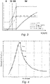
- FIG. 3 A common prior art control strategy of a variable speed wind turbine is described with reference to Fig. 3 .
- Fig. 3 the operation of a typical variable speed wind turbine is illustrated in terms of the pitch angle ( ⁇ ), the electrical power generated (P), the generator torque (M) and the rotational velocity of the rotor ( ⁇ ), as a function of the wind speed.
- the rotor In a first operational range, from the cut-in wind speed to a first wind speed (e.g. approximately 5 or 6 m/s), the rotor may be controlled to rotate at a substantially constant speed that is just high enough to be able to accurately control it.
- the cut-in wind speed may be e.g. approximately 3 m/s.
- the objective is generally to maximize power output while maintaining the pitch angle of the blades constant so as to capture maximum energy.
- the generator torque and rotor speed may be varied so as keep the tip speed ratio ⁇ (tangential velocity of the tip of the rotor blades divided by the prevailing wind speed) constant so as to maximize the power coefficient Cp.
- the generator speed substantially equals the rotor speed.
- a substantially constant ratio exists between the rotor speed and the generator speed.
- this third operational range which starts at reaching nominal rotor rotational speed and extends until reaching nominal power, the rotor speed may be kept constant, and the generator torque may be varied to such effect.
- this third operational range extends substantially from the second wind speed to the nominal wind speed e.g. from approximately 8.5 m/s to approximately 11 m/s.
- a fourth operational range which may extend from the nominal wind speed to the cut-out wind speed (for example from approximately 11 m/s to 25 m/s)
- the blades may be rotated ("pitched") to maintain the aerodynamic torque delivered by the rotor substantially constant.
- the pitch may be actuated such as to maintain the rotor speed substantially constant.
- the wind turbine's operation is interrupted.
- the blades are normally kept in a constant pitch position, namely the "below rated pitch position".
- Said default pitch position may generally be close to a 0° pitch angle. The exact pitch angle in "below rated” conditions however depends on the complete design of the wind turbine.
- the operation described above may be translated into a so-called power curve, such as the one shown in Fig. 3 .
- a power curve may reflect the theoretical optimum operation of the wind turbine.
- the aerodynamic thrust on the rotor may be high, as illustrated in Fig. 4 .
- Such a high aerodynamic thrust leads to high bending loads at the blade root.
- the high loads at the blade root in turn can lead to high loads in the tower. If a wind turbine suffers from high loads repeatedly, the fatigue life of wind turbine components such as the blades can be reduced.
- a thrust limit for the rotor which is understood as a maximum level of aerodynamic thrust on the rotor that may not be exceeded in operation.
- the operation of the wind turbine is thus adjusted, when necessary, to avoid the thrust exceeding the thrust limit. The operation thus deviates from the theoretical optimum operation, and the electrical energy output is negatively affected.
- the present disclosure is directed to a method for defining a plurality of thrust limits for a wind turbine located at a site and having a rotor with a plurality of blades, wherein the thrust limits define values of aerodynamic thrust on the rotor not to be exceeded in operation.
- the method includes providing a wind speed distribution representative for the site and defining one or more isolines of constant turbulence probability representing a turbulence parameter as a function of wind speed, wherein the isolines correspond to quantile levels of turbulence of the wind speed distribution and the turbulence parameter is indicative of wind speed variation.
- the turbulence parameter is determined by substantially continuously measuring wind speed upstream of the rotor with an active sensing system and calculating the wind speed variations from the measured wind speed.
- Turbulence ranges are defined with respect to the isolines. Thrust limits are defined for each of the turbulence ranges.
- the active sensing system uses a Doppler lidar system to generate multiple fixed measurement beams directed upwind of the wind turbine to sample an incoming wind flow.
- each of the fixed measurement beams may detect wind speed at a different angle relative to the rotor and at a plurality of different ranges from the rotor.
- the Doppler lidar system may generate five fixed measurement beams, wherein each fixed measurement beam detects wind speed at ten different ranges from the rotor.
- the wind turbine includes a nacelle and the Doppler lidar system is mounted atop the nacelle.
- the fixed measurement beams may include a center axial beam and a plurality of other beams projecting at an angle away from the center axial beam and spaced equally around a circular circumference. For example, four fixed beams may be spaced 90 degrees apart on the circular circumference. In another embodiment, the beams need not be fixed in space, but may be used in a scanning configuration.
- wind measurements from the plurality of different ranges for each fixed measurement beam are used to calculate a mean wind speed of the incoming wind flow and a standard deviation of the wind speed throughout the sampled field, wherein the standard deviation of the wind speed corresponds to the turbulence parameter.
- the wind speed measurements and calculation of the standard deviation may be performed at a rate of at least 4 Hz, and the standard deviation calculations may be smoothed by a low-pass filter.
- a filter time constant for the low-pass filter may be adjustable and selected to approximate a typical wind speed of the incoming wind flow.
- the method may include the isolines defining the standard deviation as a linear function of the wind speed within a wind speed range.
- the wind speed distribution for the site may be based on wind measurements at a site of the wind turbine.
- the method may also include selecting one of the thrust limits based on the determined turbulence parameter and the determined wind speed, and operating the wind turbine such that a thrust on the rotor is below the selected thrust limit. For example, the thrust on the rotor may be compared with the selected thrust limit, and if the thrust is above the selected thrust limit, the method includes sending a collective pitch signal to the blades of the rotor to pitch the blades and reduce the thrust on the rotor.
- the present disclosure also includes a wind turbine that includes a rotor with a plurality of blades and a pitch system configured with the blades to rotate the blades around longitudinal axes of the blades.
- the wind turbine includes an active sensing system mounted on the wind turbine, such as a Doppler lidar system that generates multiple fixed measurement beams upwind of the wind turbine to detect wind speed of an incoming wind flow.
- the wind turbine includes a control system that is in communication with the Doppler lidar system and is configured to substantially continuously measure the wind speed of the incoming wind flow and calculate a turbulence parameter corresponding to wind speed variations of the measured wind speeds.
- the control system is also configured to select a thrust level based on the turbulence parameter and the measured wind speed, wherein the thrust level is selected from a plurality of thrust limits for different turbulence ranges, the plurality of thrust limits determined by quantile-based regression of a wind speed distribution of wind speed and the turbulence parameter.
- the control system sends signals to the pitch system to collectively pitch the blades such that aerodynamic thrust on the rotor is below the selected thrust level.
- the Doppler lidar system is configured to generate multiple fixed measurement beams upwind of the wind turbine to sample the incoming wind flow, wherein each of the fixed measurement beams measures wind speed at a different angle relative to an axis of the rotor and at a plurality of different ranges from the rotor.
- the Doppler lidar system is mounted atop a nacelle of the wind turbine, the fixed measurement beams including a center axial beam and a plurality of beams projecting at an angle away from the center axial beam and spaced equally around a circular circumference.
- the control system may be configured to use the wind measurements from the plurality of different ranges for each fixed measurement beam to calculate a mean wind speed of the incoming wind flow and a standard deviation of the wind speed, wherein the standard deviation of the wind speed corresponds to the turbulence parameter.
- the control system may perform the calculations of the wind speed measurements and the standard deviation at a rate of at least 4 Hz and to smooth the standard deviation calculations with a low-pass filter.
- the control system may set the filter time constant for the low-pass filter to account for a typical wind speed of the incoming wind flow and the average range of wind speed measurements from the rotor, for example at 10 seconds to reflect a typical wind speed of 10 m/s and a travel distance of 100 meters.
- Fig. 1 illustrates a perspective view of one example of a wind turbine 1.
- the wind turbine 1 includes a tower 2 extending from a support surface 3, a nacelle 4 mounted on the tower 2, and a rotor 5 coupled to the nacelle 4.
- the rotor 5 includes a rotatable hub 6 and at least one rotor blade 7 coupled to and extending outwardly from the hub 6.
- the rotor 5 includes three rotor blades 7.
- the rotor 5 may include more or less than three rotor blades 7.
- Each rotor blade 7 may be spaced from the hub 6 to facilitate rotating the rotor 5 to enable kinetic energy to be transferred from the wind into usable mechanical energy, and subsequently, electrical energy.
- the hub 6 may be rotatably coupled to an electric generator 10 ( Fig. 2 ) positioned within the nacelle 4 or forming part of the nacelle to permit electrical energy to be produced.
- the rotation of the rotor may be directly transmitted, e.g., in direct drive wind turbines, or through the use of a gearbox to a generator.
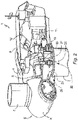
- Fig. 2 illustrates a simplified, internal view of an example of the geartrain and power generating components within the nacelle 4.
- the rotor 5 may include a main rotor shaft 8 coupled to the hub 6 for rotation therewith.
- the generator 10 may then be coupled to the rotor shaft 8 such that rotation of the rotor shaft 8 drives the generator 10.
- the generator 10 includes a generator shaft 11 rotatably coupled to the rotor shaft 8 through a gearbox 9.
- the wind turbine rotor 5 may be rotatably mounted on a support frame 12 through two rotor bearings at a coupling region.
- the support frame 12 may not extend through the hub 6 and therefore the rotor may be supported by a single rotor bearing, commonly called the main bearing.
- the generator 10 may be electrically coupled to a converter that adapts the output electrical power of the generator to the requirements of the electrical grid.
- the converter may be placed inside the nacelle 4; however, in other examples it may be placed in other locations of the wind turbine.
- the rotor 5 of the wind turbine and the generator 10 may be supported by a bedplate or a support frame 12 positioned atop the wind turbine tower 2.
- the nacelle 4 is rotatably coupled to the tower 2 through a yaw system 20.
- the yaw system comprises a yaw bearing (not visible in Fig. 2 ) having two bearing components configured to rotate with respect to the other.
- the tower 2 is coupled to a first bearing component and the nacelle 4, e.g. the bedplate or support frame 12, is coupled to the second bearing component.
- the yaw system 20 comprises an annular gear 21 and a plurality of yaw drives 22 with a motor 23, a gearbox 24 and a pinion 25 for meshing with the annular gear for rotating one of the bearing components with respect to the other.
- Fig. 3 illustrates a conventional power curve of a wind turbine according to the prior art.
- the operation of a variable speed wind turbine as a function of wind speed has hereinbefore explained. It may be noted that the operation of the wind turbine is not necessarily based on an actual direct measurement of wind speed. Rather, the wind speed may be derived or estimated from the speed of rotation of the rotor. Typically the generator speed is measured in wind turbines. From the generator speed, the rotor speed can easily be derived.
- Fig. 4 schematically illustrates an aerodynamic thrust force as a function of wind speed when a wind turbine is operated according to a theoretical power curve. As may be seen in Fig. 4 , the aerodynamic thrust on the rotor peaks around the nominal wind speed. In accordance with aspects of the present disclosure a plurality of thrust levels may be introduced to avoid the high peak in aerodynamic thrust and to thereby limit structural loads.
- a plurality of thrust limits are depicted, including a minimum, a mean, and a maximum thrust limit. Depending on the level of turbulence at a given moment, one of these thrust limits may be selected. The wind turbine is then operated to ensure that the aerodynamic thrust on the rotor stays below the selected thrust limit.
- Fig. 5 schematically illustrates an example of determining an isoline of constant turbulence probability.
- the example of Fig. 5 may be used.
- a wind speed distribution representative for the site is provided. In this specific example, a wind range from 10 m/s to 20 m/s has been provided.
- thrust limits will act in a range of wind speeds around the nominal wind speed, e.g. from 1 - 3 m/s below the nominal wind speed to 1 - 3 m/s above the nominal wind speed.
- the wind speed distribution may be obtained from wind speed measurements, e.g. using a met mast, prior to installation of the wind turbine or wind park.
- the wind speed distribution might also be obtained from wind speed measurements in similar sites or from computer simulation.
- a plurality of isolines of constant turbulence probability are defined.
- the isolines represent a turbulence parameter indicative of wind speed variation as a function of wind speed.
- the turbulence parameter is the standard deviation of the wind speed with respect to a mean wind speed.
- other turbulence parameters might be used, such as e.g. turbulence intensity or variance of wind speed.
- Turbulence intensity may be defined as standard deviation divided by mean wind speed. The standard deviation is the square root of the variance.
- the turbulence parameter is assumed to be a linear function of the wind speed.
- the isolines in Fig. 5 correspond to quantile levels of probability of turbulence of the wind speed distribution.
- the three lines correspond to 5%, 50%, and 95% quantiles (i.e., a quantile-based regression has been used).
- ⁇ lim is the standard deviation as a function of the wind speed V for one of the isolines.
- the parameters a ⁇ and b ⁇ are the parameters of the linear function.
- V on and V off are the wind speed at the lower end and the upper end of the wind range for which the linear functions are to be determined.
- the wind speed distribution may be regarded as a collection of data points of combinations of wind speed and standard deviation thereof.
- the 95% isoline represents a confidence level of 95% that turbulence in the wind speed distribution is below the indicated level, i.e. in this example, the standard deviation of wind speed for a given wind speed is below the line.
- a range of 10 m/s to 20 m/s was chosen, but it should be clear that different ranges of wind speed might be used.
- a wind speed range may be split in smaller portions e.g. 10 - 12 m/s, 12 - 14 m/s, and so on.
- quantile-based regression could be performed to find portions of an isoline.
- an isoline may comprise several linear portions.
- turbulence ranges can be defined with respect to the isolines.
- the turbulence ranges can be defined above an isoline, below an isoline, or between isolines.
- One or more of the edges or ends of the turbulence ranges are thereby defined by the isolines.
- a turbulence range may be defined below 5%
- a second turbulence range extending from 5% to 95%
- a third turbulence range may be defined for turbulence above the 95% isoline.
- thrust limits may be defined such that (peak) loads are maintained under a predefined acceptable level even in highly turbulent winds. On the other hand, if the wind is less turbulent, higher limits may be used because the peak loads will stay below an acceptable level.
- Fig. 6 schematically illustrates an example of a method of operating a wind turbine.
- a method for operating a wind turbine might comprise estimating a wind speed and the turbulence parameter and selecting a thrust limit based on the estimated turbulence parameter and the estimated wind speed. Then the wind turbine may be operated such that a thrust on the rotor is below the selected thrust limit.
- Input for block 30 includes the parameters a ⁇ i and b ⁇ i for each of n defined isolines, wherein n is the total number of isolines, and i is the number of an individual isoline.
- the output of the block 30 is one or more values of standard deviation ⁇ i for the given mean wind speed V w . In this specific case, two standard deviation values are defined for each wind speed, ⁇ 5% and ⁇ 95% .
- the wind speed V might be determined substantially continuously.
- substantially continuously herein means that the wind speed is determined with sufficiently high frequency such that it can be taken into account in a meaningful manner in wind turbine operation.
- a wind turbine may comprise a remote sensing system to measure wind conditions upstream of the rotor, e.g., a SODAR (sonic detection and ranging) or LIDAR (light detection and ranging).
- the control system of the wind turbine may be configured to receive the wind conditions from the remote sensing system and to determine the wind speed and turbulence impinging on the rotor based on the measurements of the wind upstream.
- the wind turbine may comprise a nacelle anemometer
- the control system is configured to determine wind speed and turbulence based on measurements of the nacelle anemometer (i.e., the nacelle anemometer gives continuous measurements of wind speed V). For an interval (the most recent interval), a mean wind speed V w , and a wind speed variation (in this example standard deviation ⁇ w ) might be calculated from the data from the nacelle anemometer.
- a mean wind speed V w the most recent interval
- a wind speed variation in this example standard deviation ⁇ w
- the wind speed may be estimated by determining a power output, a pitch angle of the blades and a rotational speed of the rotor. Based on the power output, the pitch angle of the blades and the rotational speed of the rotor, wind speed may be estimated using a Kalman filter.
- suitable sensors and systems are provided on a wind turbine to measure power output, a pitch angle from the blades (this should be available for suitable pitch control) and the rotational speed of the rotor (typically, the speed of rotation of the generator rotor may be measured).
- the use of a Kalman filter has been found to be reliable to estimate wind speed.
- the mean wind speed V w and the turbulence parameter indicative of variation of the wind speed may be derived at block 40.
- One of the outputs of block 40 is the chosen turbulence parameter, which in this case is the standard deviation ⁇ w of the wind speed.
- the output of block 40 is provided as input to blocks 30 and 50.
- a plurality of turbulence ranges is defined, for example, below the lowest quantile level, above the highest quantile level, and between the lowest and highest quantile levels.
- a thrust limit is defined for each of the turbulence ranges.
- T max is the highest thrust limit
- Tmin is the lowest thrust limit
- T mean is the average thrust limit.
- the suitable thrust limit T sel may be selected from the previously defined thrust limits at block 50.
- the wind turbine may then be operated to make sure that the aerodynamic thrust on the rotor stays below the selected limit.
- the aerodynamic thrust on the rotor could be measured directly, e.g. using suitable strain or deformation sensors in the blades.
- the thrust on the rotor can be estimated by calculating the thrust based on the estimated wind speed, the rotational speed of the rotor and the pitch angle of the blades.
- an estimated thrust on the rotor can be compared with the selected thrust limit, and if the estimated thrust is above the selected thrust limit, a collective pitch signal may be sent (from the wind turbine control) to the blades of the rotor (or to the pitch control systems) to pitch the blades and reduce the thrust on the rotor.
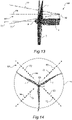
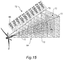
- FIG. 12-15 An alternative embodiment of a method and system for detecting and measuring actual turbulence in the incoming wind flow is depicted generally in Figs. 12-15 .
- This method and system utilizes an active sensing system 60 mounted on the wind turbine 1, for example atop the nacelle 4, to detect wind speed in the wind flow at a plurality of distances/ranges 66 upstream of the rotor 5, as explained in greater detail below.
- the wind speed measurements are then used to derive a measure of turbulence intensity (wind speed variations) that is provided to the thrust limiting control process ( Fig. 12 ).
- the embodiment of Figs. 12-15 may provide distinct advantages as compared to measuring wind speed from a nacelle-mounted anemometer or from estimating wind speed from a power output, a pitch angle of the blades and a rotational speed of the rotor.
- the standard deviation of wind speed within a sliding data window is computed, wherein the time length of the data window can be relatively long, for example up to 60 seconds, which may be undesirable in that the turbulence intensity estimate may be slow to respond to actual turbulence changes.
- relatively large wind excursions in the measured wind speed may unduly influence the wind turbulence estimate for a prolonged time.
- the embodiment of Figs. 12-15 may be desired in certain environments to address these potential drawbacks.
- the active sensing system 60 may be implemented by Doppler lidar system 62 that generates multiple fixed measurement beams 64 directed upwind of the wind turbine rotor 5 to sample the incoming wind flow.
- the fixed measurement beams 64 may be directed outwardly from the Doppler lidar system 62 at an angle relative to the axis 70 of the rotor 5 so as to define an increasing sample field as distance from the rotor 5 increases, as can be appreciated from Figs. 13 and 15 .
- Each of the fixed measurement beams 64 may detect and measure wind speed at a plurality of distances from the system 62. For example, in Fig. 15 , each beam 64 detects and measures wind speed at ten separate distances or ranges 66 from the system 62, wherein the range points 66 are twenty meters apart. It should be appreciated that the number of fixed measurement beams 64, number of range points 66 along each beam 64, and distances between the range points 66 can vary for different embodiments, including embodiments that use a configuration of scanning beams rather than fixed beams.
- the Doppler lidar system 60 generates five of the fixed measurement beams 64, wherein one of these beams is a central beam 68 oriented essentially parallel to the rotor axis 70.
- the other beams 72 are spaced equally around a circular circumference 74.
- the four fixed beams 72 may be spaced 90 degrees apart on the circular circumference 70.
- Fig. 12 depicts the thrust limiting control process of Fig. 6 specifically modified to utilize the information from the Doppler lidar system 60.
- the plurality of signals from the fixed measurement beams 64 are input to the controller.
- the wind speed measurements form the different range points 66 for each beam 64 are used to calculate the mean wind speed V w of the incoming wind flow and the standard deviation ⁇ w of the wind speed.
- the standard deviation ⁇ w is input into to the process block 50 (as the turbulence intensity parameter) and used as discussed above with respect to block 50 in Fig. 6 .
- the estimation of the standard deviation ⁇ w of the mean wind speed at process block 40 in Fig. 6 is eliminated.
- the mean wind speed V w of the incoming wind flow calculated at process block 55 may be used as the input to process block 30 (as indicated by the dashed line in Fig. 12 ) wherein the estimation of the mean wind speed V w at process block 40 discussed above with respect to Fig. 6 can also be eliminated.
- the standard deviation ⁇ w of the wind speed from process block 55 may be input to the process block 40 and used as a check on the estimated value derived at process block 40.
- the wind speed measurements and calculation of the mean wind speed V w and standard deviation ⁇ w of the wind speed are determined substantially continuously, meaning that the wind speed is determined with sufficiently high frequency such that it can be taken into account in a meaningful manner in wind turbine operation.
- the measurements and calculations may be performed at a rate of at least 4 Hz.
- the standard deviation calculations may be smoothed by a low-pass filter having a filter time constant is adjustable and selected to account for a typical wind speed of the incoming wind flow and the average range of wind speed measurements from the rotor, for example at 10 seconds to reflect a typical wind speed of 10 m/s and a travel distance of 100 meters.
- the method may include the isolines defining the standard deviation as a linear function of the wind speed within a wind speed range.
- the wind speed distribution for the site may be based on wind measurements at a site of the wind turbine.
- the method of Figs. 12-15 may also include selecting one of the thrust limits based on the determined turbulence parameter and the determined wind speed, and operating the wind turbine such that a thrust on the rotor is below the selected thrust limit. For example, the thrust on the rotor may be compared with the selected thrust limit, and if the thrust is above the selected thrust limit, the method includes sending a collective pitch signal to the blades of the rotor to pitch the blades and reduce the thrust on the rotor.
- a wind turbine comprising a rotor with a plurality of blades, one or more pitch systems for rotating the blades around longitudinal axes of the blades, a generator and a control system.
- the control system is configured to estimate a wind speed and a turbulence, and to select a thrust level based on the turbulence and the estimated wind speed, wherein the thrust level is selected from a plurality of thrust limits for different turbulence ranges, and to send signals to the pitch systems to collectively pitch the blades such that aerodynamic thrust on the rotor is below the selected thrust level.
- the plurality of thrust levels has been determined by quantile-based regression of a wind speed distribution of wind speed and a parameter indicative of turbulence.
- control system may use a Kalman filter technique to estimate the wind speed, with the Kalman filter being fed by variables such as the power output, the blade pitch angle and the rotational speed of the rotor.
- control system is in communication with the active sensing system 60 of Figs. 12-15 and is configured to substantially continuously measure the wind speed of the incoming wind flow and to calculate a turbulence parameter corresponding to wind speed variations of the measured wind speeds, as discussed above.
- the wind turbine may utilize the Doppler lidar system 62 discussed above to generate the multiple fixed measurement beams 64 directed upwind of the wind turbine to sample the incoming wind flow, wherein each of the fixed measurement beams detects wind speed at a different angle relative to the axis 70 of the rotor 5 and at a plurality of different ranges 66 from the rotor 5.
- Doppler lidar system 62 is mounted atop a nacelle 4 of the wind turbine 1.
- the fixed measurement beams 64 may include a center axial beam 68 and a plurality of other beams 72 projecting at an angle away from the center axial beam to define an increasing sample field as distance from the rotor 5 increases, wherein the beams 72 are spaced equally around a circular circumference 74.
- Figures 7 - 9 schematically illustrate the effect of dynamic thrust levels for different wind distributions.
- Figures 7 - 9 illustrate different wind speed distributions for the same wind turbine at a given site.
- quantile levels of turbulence probability have been defined.
- the wind has relatively low turbulence intensity.
- the wind speed distribution is average, or substantially comparable to the theoretical wind speed distribution.
- Fig. 9 a wind speed distribution that has relatively high turbulence is shown.
- the thrust limit that will be selected often is a high limit, prioritizing energy production.
- the thrust limit that will more often be selected is a rather low limit, sacrificing power output but ensuring that loads stay under a predefined limit.
- the wind turbine may incorporate some form of control to avoid rapidly changing thrust limits. This could happen, for example, when the turbulence is close to an isoline.
- hysteresis control may be incorporated.
- One way to implement such a control might be a time delay between entering a thrust range and the selection of a thrust limit.
- Another way to implement such a control is to have separations between turbulence ranges, and to (linearly) vary the thrust limits between the defined thrust ranges.
- one or more check levels are defined, and wherein a thrust limit is not changed until the wind turbulence parameter reaches one of the check levels.
- the check levels may define small bands around the isolines.
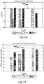
- FIG. 10 schematically illustrate the effect of varying thrust levels on the annual energy yield and the blade root bending moments.
- AEP Annual Energy Production
- the three different settings include a single high thrust limit T mean , a single low thrust limit T min , and a plurality of thrust limits Tvar.
- the variable thrust limits include Tmin, Tmean, and a Tmax higher than Tmean as defined in accordance with examples of the present disclosure.
- the three scenarios include wind speed simulations with different levels of turbulence intensity, indicated with letters A, B and C. Scenario A corresponds to a scenario with relatively low or little turbulence, scenario B corresponds to "average" turbulence, whereas scenario corresponds to a highly turbulent winds.
- Fig. 11 the bending moment at the blade root for the same three settings (T mean , T min , T var ) and same three simulated scenarios (A, B and C) are shown. It may be seen in Fig. 10 that dynamically varying the thrust limits results in an increased annual energy production in the scenarios A and B. It may be seen in Fig. 11 that dynamically varying thrust limits also ensure that loads are controlled. In the most turbulent wind scenario (C), the blade root moment reaches its limit for the control with a single high thrust limit. In scenario C, the single thrust limit yields slightly higher annual energy production but at a significant cost of high loads. These high loads may result in fatigue damage which may lead to a worse performance in the future or to premature replacement or retirement of the wind turbine or its components.
- a method for operating a wind turbine including a rotor with a plurality of blades may comprise determining a time series of wind speeds and deriving a mean wind speed and a turbulence parameter indicating variability of the wind speed from the time series. Then, a thrust limit may be selected from a plurality of thrust limits based on the derived turbulence parameter and wind speed. Based on the selected thrust limit, the wind turbine may be operated to ensure that a thrust on the rotor is below the selected thrust limit.
- the plurality of thrust limits may be defined for ranges of the turbulence parameter for each possible wind speed (within a wind speed range).
- the ranges of the turbulence parameter at given mean wind speeds are defined by confidence intervals that the turbulence parameter for the mean wind speed is below a given value in wind data representative for a location of the wind turbine.
- the wind data representative for a location of the wind turbine includes data for a band of wind speeds including a nominal wind speed of the wind turbine. It is for wind speeds around the nominal wind speed that the aerodynamic thrust on the rotor and the corresponding loads can be high. For wind speeds close to a cut-in wind speed, and wind speeds that are significantly higher than the nominal wind speed, that the aerodynamic thrust is relatively low. In the former case, this is because the energy of the wind is low and in the latter case, this is because the blades of the wind turbine have already been pitched to sufficiently high pitch angles to keep the rotor torque at nominal level. The wind speeds close to a cut-in wind speed and close to cut-out wind speed, or significantly higher than a nominal wind speed, may be safely excluded from such a probability analysis.
Landscapes
- Engineering & Computer Science (AREA)
- Life Sciences & Earth Sciences (AREA)
- Sustainable Development (AREA)
- Sustainable Energy (AREA)
- Chemical & Material Sciences (AREA)
- Combustion & Propulsion (AREA)
- Mechanical Engineering (AREA)
- General Engineering & Computer Science (AREA)
- Physics & Mathematics (AREA)
- Fluid Mechanics (AREA)
- Electromagnetism (AREA)
- General Physics & Mathematics (AREA)
- Computer Networks & Wireless Communication (AREA)
- Radar, Positioning & Navigation (AREA)
- Remote Sensing (AREA)
- Acoustics & Sound (AREA)
- Multimedia (AREA)
- Aviation & Aerospace Engineering (AREA)
- Wind Motors (AREA)
Applications Claiming Priority (1)
| Application Number | Priority Date | Filing Date | Title |
|---|---|---|---|
| US17/144,377 US11408396B2 (en) | 2021-01-08 | 2021-01-08 | Thrust control for wind turbines using active sensing of wind turbulence |
Publications (1)
| Publication Number | Publication Date |
|---|---|
| EP4027009A1 true EP4027009A1 (fr) | 2022-07-13 |
Family
ID=79185914
Family Applications (1)
| Application Number | Title | Priority Date | Filing Date |
|---|---|---|---|
| EP22150054.9A Pending EP4027009A1 (fr) | 2021-01-08 | 2022-01-03 | Contrôle de la poussée des éoliennes par détection active de la turbulence du vent |
Country Status (5)
| Country | Link |
|---|---|
| US (1) | US11408396B2 (fr) |
| EP (1) | EP4027009A1 (fr) |
| JP (1) | JP2022107523A (fr) |
| KR (1) | KR20220100526A (fr) |
| CN (1) | CN114753973A (fr) |
Cited By (1)
| Publication number | Priority date | Publication date | Assignee | Title |
|---|---|---|---|---|
| CN116221014A (zh) * | 2023-04-28 | 2023-06-06 | 凯宸能源科技(天津)有限公司 | 基于激光雷达风电机组净空控制方法、装置、系统及介质 |
Citations (3)
| Publication number | Priority date | Publication date | Assignee | Title |
|---|---|---|---|---|
| EP3273055A1 (fr) * | 2016-07-13 | 2018-01-24 | General Electric Company | Systèmes et procédés de correction de l'induction pour commande de turbine éolienne assistée par lidar |
| US20200124026A1 (en) * | 2017-06-21 | 2020-04-23 | IFP Energies Nouvelles | Method for acquiring and modelling an incident wind field by means of a lidar sensor |
| EP3705716A1 (fr) * | 2019-03-04 | 2020-09-09 | GE Renewable Germany GmbH | Limites de poussée pour éoliennes |
Family Cites Families (23)
| Publication number | Priority date | Publication date | Assignee | Title |
|---|---|---|---|---|
| US7822560B2 (en) * | 2004-12-23 | 2010-10-26 | General Electric Company | Methods and apparatuses for wind turbine fatigue load measurement and assessment |
| US7351033B2 (en) * | 2005-09-09 | 2008-04-01 | Mcnerney Gerald | Wind turbine load control method |
| US7342323B2 (en) * | 2005-09-30 | 2008-03-11 | General Electric Company | System and method for upwind speed based control of a wind turbine |
| CN101684774B (zh) * | 2008-09-28 | 2012-12-26 | 通用电气公司 | 一种风力发电系统及风力发电机的测风方法 |
| US8025476B2 (en) * | 2009-09-30 | 2011-09-27 | General Electric Company | System and methods for controlling a wind turbine |
| GB2476507A (en) * | 2009-12-23 | 2011-06-29 | Vestas Wind Sys As | Method And Apparatus For Protecting Wind Turbines From Gust Damage |
| WO2012097076A2 (fr) * | 2011-01-11 | 2012-07-19 | Ophir Corporation | Procédés et appareil de surveillance de champs de flux complexes pour des applications d'éolienne |
| US9804262B2 (en) | 2011-10-10 | 2017-10-31 | Vestas Wind Systems A/S | Radar weather detection for a wind turbine |
| US10180129B2 (en) * | 2012-01-23 | 2019-01-15 | Mhi Vestas Offshore Wind A/S | Coordinated control of a floating wind turbine |
| WO2014018957A1 (fr) * | 2012-07-27 | 2014-01-30 | Texas Tech University System | Appareil et procédé d'utilisation de radar pour évaluer des champs d'écoulement de vent pour des applications d'énergie éolienne |
| US9335229B2 (en) * | 2013-03-15 | 2016-05-10 | Frontier Wind, Llc | Load distribution estimation |
| DE102013205838A1 (de) | 2013-04-03 | 2014-10-09 | Senvion Se | Effizienzüberwachungsverfahren eines Windenergieanlagenparks |
| DK2799711T3 (en) | 2013-05-03 | 2017-10-23 | Ge Renewable Tech Wind Bv | Method of operating a wind turbine |
| US9624905B2 (en) | 2013-09-20 | 2017-04-18 | General Electric Company | System and method for preventing excessive loading on a wind turbine |
| US9631606B2 (en) | 2014-04-14 | 2017-04-25 | General Electric Company | System and method for thrust-speed control of a wind turbine |
| EP3158190B1 (fr) | 2014-06-20 | 2019-04-17 | Mita-Teknik A/S | Système pour limitation de poussée de turbines éoliennes |
| WO2016023554A1 (fr) | 2014-08-15 | 2016-02-18 | Vestas Wind Systems A/S | Augmentation de la puissance nominale de turbine à l'aide d'une prédiction de turbulence |
| US10036692B2 (en) * | 2014-11-13 | 2018-07-31 | General Electric Company | System and method for estimating rotor blade loads of a wind turbine |
| WO2016138647A1 (fr) | 2015-03-04 | 2016-09-09 | General Electric Company | Système et procédé d'atténuation de charges sur une turbine éolienne |
| WO2016150442A1 (fr) * | 2015-03-20 | 2016-09-29 | Vestas Wind Systems A/S | Amortissement d'oscillations dans une turbine éolienne |
| CN106812658B (zh) | 2015-11-27 | 2019-09-06 | 中国船舶重工集团海装风电股份有限公司 | 一种风力发电机组的控制方法及装置 |
| CN110520621B (zh) | 2017-04-05 | 2021-09-03 | 维斯塔斯风力系统集团公司 | 取决于空气密度的涡轮机操作 |
| US20210222672A1 (en) * | 2020-01-16 | 2021-07-22 | General Electric Company | Systems and methods for operation of wind turbines using improved power curves |
-
2021
- 2021-01-08 US US17/144,377 patent/US11408396B2/en active Active
-
2022
- 2022-01-03 EP EP22150054.9A patent/EP4027009A1/fr active Pending
- 2022-01-04 KR KR1020220000960A patent/KR20220100526A/ko unknown
- 2022-01-06 JP JP2022000809A patent/JP2022107523A/ja active Pending
- 2022-01-07 CN CN202210023906.XA patent/CN114753973A/zh active Pending
Patent Citations (3)
| Publication number | Priority date | Publication date | Assignee | Title |
|---|---|---|---|---|
| EP3273055A1 (fr) * | 2016-07-13 | 2018-01-24 | General Electric Company | Systèmes et procédés de correction de l'induction pour commande de turbine éolienne assistée par lidar |
| US20200124026A1 (en) * | 2017-06-21 | 2020-04-23 | IFP Energies Nouvelles | Method for acquiring and modelling an incident wind field by means of a lidar sensor |
| EP3705716A1 (fr) * | 2019-03-04 | 2020-09-09 | GE Renewable Germany GmbH | Limites de poussée pour éoliennes |
Cited By (2)
| Publication number | Priority date | Publication date | Assignee | Title |
|---|---|---|---|---|
| CN116221014A (zh) * | 2023-04-28 | 2023-06-06 | 凯宸能源科技(天津)有限公司 | 基于激光雷达风电机组净空控制方法、装置、系统及介质 |
| CN116221014B (zh) * | 2023-04-28 | 2023-10-20 | 凯宸能源科技(天津)有限公司 | 基于激光雷达风电机组净空控制方法、装置、系统及介质 |
Also Published As
| Publication number | Publication date |
|---|---|
| CN114753973A (zh) | 2022-07-15 |
| US20220220935A1 (en) | 2022-07-14 |
| KR20220100526A (ko) | 2022-07-15 |
| US11408396B2 (en) | 2022-08-09 |
| JP2022107523A (ja) | 2022-07-21 |
Similar Documents
| Publication | Publication Date | Title |
|---|---|---|
| EP2762721B1 (fr) | Procédé et appareil de réduction de bruit de turbine éolienne | |
| EP2795109B1 (fr) | Procédé de commande pour une turbine éolienne et turbine éolienne | |
| EP2588755B1 (fr) | Etalonnage de capteur d'éolienne | |
| EP2582973B1 (fr) | Procédé de commande pour éolienne | |
| US20180245568A1 (en) | A Wind Turbine and a Method of Operating a Wind Turbine with a Rotational Speed Exclusion Zone | |
| EP2306003A2 (fr) | Procédé et dispositif pour le réglage d'une éolienne | |
| US20120128488A1 (en) | Rotor-sector based control of wind turbines | |
| EP2607689B1 (fr) | Commande pour éoliennes fonctionnant par section de rotor | |
| US20200347822A1 (en) | Thrust Limits for Wind Turbines | |
| EP2719895B1 (fr) | Procédé de supervision d'une éolienne | |
| EP3346125A1 (fr) | Procédés de commande de turbine éolienne comportant une compensation de torsion à commande de poussée | |
| EP3112675A1 (fr) | Agencement de commande et procédé de détection et de prévention de situations de désalignement de turbine éolienne | |
| EP3249218B1 (fr) | Système et procédé d'implantation d'un parc éolien pour optimiser les charges | |
| US11242841B2 (en) | System and method for controlling a wind turbine based on a collective pitch-offset | |
| EP4027009A1 (fr) | Contrôle de la poussée des éoliennes par détection active de la turbulence du vent | |
| EP2927483A1 (fr) | Régulation du bruit dans des éoliennes | |
| KR20150081663A (ko) | 풍력발전 시스템의 피치제어 장치 및 그 방법 | |
| US20230323857A1 (en) | Method and controller arrangement for operating a wind turbine farm | |
| EP4124748A1 (fr) | Systèmes et procédés d'exploitation d'un parc éolien |
Legal Events
| Date | Code | Title | Description |
|---|---|---|---|
| PUAI | Public reference made under article 153(3) epc to a published international application that has entered the european phase |
Free format text: ORIGINAL CODE: 0009012 |
|
| STAA | Information on the status of an ep patent application or granted ep patent |
Free format text: STATUS: THE APPLICATION HAS BEEN PUBLISHED |
|
| AK | Designated contracting states |
Kind code of ref document: A1 Designated state(s): AL AT BE BG CH CY CZ DE DK EE ES FI FR GB GR HR HU IE IS IT LI LT LU LV MC MK MT NL NO PL PT RO RS SE SI SK SM TR |
|
| STAA | Information on the status of an ep patent application or granted ep patent |
Free format text: STATUS: REQUEST FOR EXAMINATION WAS MADE |
|
| 17P | Request for examination filed |
Effective date: 20230112 |
|
| RBV | Designated contracting states (corrected) |
Designated state(s): AL AT BE BG CH CY CZ DE DK EE ES FI FR GB GR HR HU IE IS IT LI LT LU LV MC MK MT NL NO PL PT RO RS SE SI SK SM TR |
|
| P01 | Opt-out of the competence of the unified patent court (upc) registered |
Effective date: 20230529 |
|
| STAA | Information on the status of an ep patent application or granted ep patent |
Free format text: STATUS: EXAMINATION IS IN PROGRESS |
|
| 17Q | First examination report despatched |
Effective date: 20240403 |