EP3270137B1 - Device for measuring the dynamic stress/strain response of ductile materials - Google Patents
Device for measuring the dynamic stress/strain response of ductile materials Download PDFInfo
- Publication number
- EP3270137B1 EP3270137B1 EP17180769.6A EP17180769A EP3270137B1 EP 3270137 B1 EP3270137 B1 EP 3270137B1 EP 17180769 A EP17180769 A EP 17180769A EP 3270137 B1 EP3270137 B1 EP 3270137B1
- Authority
- EP
- European Patent Office
- Prior art keywords
- bar
- specimen mount
- striker bar
- striker
- test sample
- Prior art date
- Legal status (The legal status is an assumption and is not a legal conclusion. Google has not performed a legal analysis and makes no representation as to the accuracy of the status listed.)
- Active
Links
Images


Classifications
-
- G—PHYSICS
- G01—MEASURING; TESTING
- G01N—INVESTIGATING OR ANALYSING MATERIALS BY DETERMINING THEIR CHEMICAL OR PHYSICAL PROPERTIES
- G01N3/00—Investigating strength properties of solid materials by application of mechanical stress
- G01N3/30—Investigating strength properties of solid materials by application of mechanical stress by applying a single impulsive force, e.g. by falling weight
- G01N3/307—Investigating strength properties of solid materials by application of mechanical stress by applying a single impulsive force, e.g. by falling weight generated by a compressed or tensile-stressed spring; generated by pneumatic or hydraulic means
-
- G—PHYSICS
- G01—MEASURING; TESTING
- G01N—INVESTIGATING OR ANALYSING MATERIALS BY DETERMINING THEIR CHEMICAL OR PHYSICAL PROPERTIES
- G01N3/00—Investigating strength properties of solid materials by application of mechanical stress
- G01N3/08—Investigating strength properties of solid materials by application of mechanical stress by applying steady tensile or compressive forces
-
- G—PHYSICS
- G01—MEASURING; TESTING
- G01N—INVESTIGATING OR ANALYSING MATERIALS BY DETERMINING THEIR CHEMICAL OR PHYSICAL PROPERTIES
- G01N3/00—Investigating strength properties of solid materials by application of mechanical stress
- G01N3/02—Details
-
- G—PHYSICS
- G01—MEASURING; TESTING
- G01N—INVESTIGATING OR ANALYSING MATERIALS BY DETERMINING THEIR CHEMICAL OR PHYSICAL PROPERTIES
- G01N3/00—Investigating strength properties of solid materials by application of mechanical stress
- G01N3/02—Details
- G01N3/04—Chucks
-
- G—PHYSICS
- G01—MEASURING; TESTING
- G01N—INVESTIGATING OR ANALYSING MATERIALS BY DETERMINING THEIR CHEMICAL OR PHYSICAL PROPERTIES
- G01N3/00—Investigating strength properties of solid materials by application of mechanical stress
- G01N3/30—Investigating strength properties of solid materials by application of mechanical stress by applying a single impulsive force, e.g. by falling weight
-
- G—PHYSICS
- G01—MEASURING; TESTING
- G01N—INVESTIGATING OR ANALYSING MATERIALS BY DETERMINING THEIR CHEMICAL OR PHYSICAL PROPERTIES
- G01N2203/00—Investigating strength properties of solid materials by application of mechanical stress
- G01N2203/0001—Type of application of the stress
- G01N2203/001—Impulsive
-
- G—PHYSICS
- G01—MEASURING; TESTING
- G01N—INVESTIGATING OR ANALYSING MATERIALS BY DETERMINING THEIR CHEMICAL OR PHYSICAL PROPERTIES
- G01N2203/00—Investigating strength properties of solid materials by application of mechanical stress
- G01N2203/0014—Type of force applied
- G01N2203/0016—Tensile or compressive
- G01N2203/0017—Tensile
-
- G—PHYSICS
- G01—MEASURING; TESTING
- G01N—INVESTIGATING OR ANALYSING MATERIALS BY DETERMINING THEIR CHEMICAL OR PHYSICAL PROPERTIES
- G01N2203/00—Investigating strength properties of solid materials by application of mechanical stress
- G01N2203/003—Generation of the force
- G01N2203/0032—Generation of the force using mechanical means
- G01N2203/0035—Spring
-
- G—PHYSICS
- G01—MEASURING; TESTING
- G01N—INVESTIGATING OR ANALYSING MATERIALS BY DETERMINING THEIR CHEMICAL OR PHYSICAL PROPERTIES
- G01N2203/00—Investigating strength properties of solid materials by application of mechanical stress
- G01N2203/003—Generation of the force
- G01N2203/0055—Generation of the force using mechanical waves, e.g. acoustic
-
- G—PHYSICS
- G01—MEASURING; TESTING
- G01N—INVESTIGATING OR ANALYSING MATERIALS BY DETERMINING THEIR CHEMICAL OR PHYSICAL PROPERTIES
- G01N2203/00—Investigating strength properties of solid materials by application of mechanical stress
- G01N2203/0058—Kind of property studied
- G01N2203/0092—Visco-elasticity, solidification, curing, cross-linking degree, vulcanisation or strength properties of semi-solid materials
- G01N2203/0094—Visco-elasticity
-
- G—PHYSICS
- G01—MEASURING; TESTING
- G01N—INVESTIGATING OR ANALYSING MATERIALS BY DETERMINING THEIR CHEMICAL OR PHYSICAL PROPERTIES
- G01N2203/00—Investigating strength properties of solid materials by application of mechanical stress
- G01N2203/0098—Tests specified by its name, e.g. Charpy, Brinnel, Mullen
-
- G—PHYSICS
- G01—MEASURING; TESTING
- G01N—INVESTIGATING OR ANALYSING MATERIALS BY DETERMINING THEIR CHEMICAL OR PHYSICAL PROPERTIES
- G01N2203/00—Investigating strength properties of solid materials by application of mechanical stress
- G01N2203/02—Details not specific for a particular testing method
- G01N2203/025—Geometry of the test
- G01N2203/0252—Monoaxial, i.e. the forces being applied along a single axis of the specimen
-
- G—PHYSICS
- G01—MEASURING; TESTING
- G01N—INVESTIGATING OR ANALYSING MATERIALS BY DETERMINING THEIR CHEMICAL OR PHYSICAL PROPERTIES
- G01N2203/00—Investigating strength properties of solid materials by application of mechanical stress
- G01N2203/02—Details not specific for a particular testing method
- G01N2203/026—Specifications of the specimen
- G01N2203/0262—Shape of the specimen
- G01N2203/0278—Thin specimens
-
- G—PHYSICS
- G01—MEASURING; TESTING
- G01N—INVESTIGATING OR ANALYSING MATERIALS BY DETERMINING THEIR CHEMICAL OR PHYSICAL PROPERTIES
- G01N2203/00—Investigating strength properties of solid materials by application of mechanical stress
- G01N2203/02—Details not specific for a particular testing method
- G01N2203/06—Indicating or recording means; Sensing means
- G01N2203/0641—Indicating or recording means; Sensing means using optical, X-ray, ultraviolet, infrared or similar detectors
- G01N2203/0647—Image analysis
-
- G—PHYSICS
- G01—MEASURING; TESTING
- G01N—INVESTIGATING OR ANALYSING MATERIALS BY DETERMINING THEIR CHEMICAL OR PHYSICAL PROPERTIES
- G01N2203/00—Investigating strength properties of solid materials by application of mechanical stress
- G01N2203/02—Details not specific for a particular testing method
- G01N2203/06—Indicating or recording means; Sensing means
- G01N2203/067—Parameter measured for estimating the property
- G01N2203/0676—Force, weight, load, energy, speed or acceleration
Definitions
- the present teachings relate to the field of materials metrology and, more particularly, to a device for measuring stress and strain characteristics of a flexible pliable material or another material.
- a Split-Hopkinson pressure bar may be used to test the dynamic stress-strain response of materials.
- a specimen or test sample is placed between, and physically contacts, an incident bar and a transmission bar.
- a stress wave, pressure wave, or incident wave is created using a striker bar.
- the incident wave propagates through the incident bar from the first end toward a second end that physically contacts the specimen.
- a first portion of the energy from the incident wave travels through the specimen while a second portion is reflected away from the specimen and back through the incident bar.
- the first portion of the wave travels through, stresses, and deforms the specimen, and is then transferred to the transmission bar that physically contacts the specimen. Movement of the transmission bar may be stopped by a momentum bar and a momentum trap.
- the Split-Hopkinson pressure bar subjects a test sample between the incident bar and the transmission bar to a compressive force as the incident wave travels through the test sample.
- the Split-Hopkinson pressure bar may thus test materials in tension, but does not function well for specimens that have a high strain to failure.
- testing of a specimen using the Split-Hopkinson pressure bar subjects the material to a non-constant strain rate as the incident wave propagates back and forth through the incident bar and the transmission bar.
- the Split-Hopkinson pressure bar thus provides a high strain rate but not a high strain.
- Other devices using servo-mechanical methods may provide high strain but not a high strain rate.
- a device that is suitable for measuring various characteristics such as tensile strength and failure stresses at a constant strain rate of various materials such as flexible, pliable, and ductile materials, as well as other materials, that provides both a high strain rate and high strain, would be a welcome addition to the art.
- CN 203643279 describes a device for measuring the dynamic shearing property of a material, and which belongs to the technical field of testers.
- a test sample slot is formed in one end of a test sample fixing support; a screw hole is formed in each of two sides of the test sample slot; a shearing test sample is locked in the test sample slot through fixing screws; a cuboid punching head is arranged at one end of a shearing impact pressing head; therefore, the material dynamic shearing property measurement device is assembled and is arranged between an incidence rod and a transmission rod of a separate type Hopkinson pressing rod; the dynamic shearing property of the material can be directly measured by a conventional elastic wave excitation mode and a stress wave signal collection and processing method.
- the apparatus comprises means for measuring an effect of the tensile stress on the test sample; a striker bar; a stretcher bar; a drive assembly configured to propel the striker bar toward the stretcher bar; a stationary specimen mount configured to receive a first portion of the test sample and to maintain the first portion of the test sample in a fixed position; and a movable specimen mount attached to a first end of the stretcher bar, the movable specimen mount configured to receive a second portion of the test sample.
- the striker bar is aligned with the stretcher bar and the striker bar is configured to impact with the movable specimen mount.
- the stretcher bar and the movable specimen mount are configured to move away from the stationary specimen mount from an impact of the striker bar with the movable specimen mount during a test or measurement of the test sample.
- the method comprises: (a) propelling the striker bar toward the stretcher bar; (b) impacting the movable specimen mount with the striker bar; (c) moving the movable specimen mount away from the stationary specimen mount resulting from the striker bar impacting the movable specimen mount; (d) applying the dynamic tensile stress and/or strain to the test sample attached to the stationary specimen mount and to the movable specimen mount resulting from the moving of the movable specimen mount away from the stationary specimen mount; and (e) measuring the effect of the tensile stress on the test sample.
- FIGS. It should be noted that some details of the FIGS. have been simplified and are drawn to facilitate understanding of the present teachings rather than to maintain strict structural accuracy, detail, and scale.
- the present teachings provide a method and structure for testing and/or obtaining performance data on a test specimen such as an elastic or non-elastic material sample.
- the method may include the dynamic measurement of tensile strength of the material sample over a relatively constant strain rate. While some conventional measurement techniques propagate a pressure wave back and forth multiple times through various device structures as well as the test specimen, which results in a non-constant stress/strain on the test specimen, a device or test structure of the present teachings may, in some embodiments, have a decreased pressure wave propagation through various device structures and the test sample, thereby resulting in more accurate stress and/or strain data.
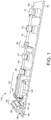
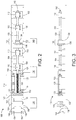
- FIG. 1 is a perspective depiction
- FIG. 2 is a plan view
- FIG. 3 is a side view, of a device or apparatus 100 for testing and/or measuring tensile characteristics, performance data, or other physical properties of a test sample.
- FIGS. 1-3 depict an exemplary structure, and that a measurement device in accordance with the present teachings may include other device substructures that are not depicted for simplicity, while various depicted device substructures may be removed or modified.
- the device 100 may include a base 102 to which other measurement device substructures are attached and/or mounted using one or more fasteners, for example, one or more screws, bolts, pegs, clips, clamps, adhesives, etc. (not individually depicted for simplicity).
- the measurement device 100 further includes a striker bar 104, a stretcher bar 106, and a specimen mounting assembly 108.
- the device 100 may further include one or more striker bar supports 110 attached to the base 102 that guide and support the striker bar 104, and allow axial movement of the striker bar 104 toward and away from the stretcher bar 106 during use.
- Each striker bar support 110 may include one or more bearings 500 ( FIG. 5 ), such as one or more bushings (for example, solid sleeve bushings or split bushings), roller bearings, or other low-friction supports, that support and allow low-friction axial movement of the striker bar 104.
- the device 100 may also include one or more stretcher bar supports 112 attached to the base 102 that guide and support the stretcher bar 106 and allow axial movement of the stretcher bar 106 away from the striker bar 104 during use.
- Each stretcher bar support 112 may include one or more bearings, such as one or more bushings (for example, solid sleeve bushings or split bushings), roller bearings, or other low-friction supports, that support and allow low-friction axial movement of the stretcher bar 106.
- the device 100 of FIGS. 1-3 further includes a drive assembly 114 and a release assembly 116.
- the drive assembly 114 is configured to propel the striker bar 104 toward the stretcher bar 106 using, for example, one or more springs, compressed gas, or another method.
- the force with which the drive assembly 114 propels the striker bar 104 may be adjustable, for example, to accommodate different test sample materials and test conditions.
- the release assembly 116 is configured to maintain or hold the striker bar 104 in a ready, engaged, or cocked position and to release the striker bar 104 to initiate a test or measurement (hereinafter, collectively, "test") of the test sample.
- test test or measurement
- the spring may be held under tension when the device 100 is in the ready position.
- a drive assembly 114 including a fast acting gas valve the gas may be pressurized within a canister when the device 100 is in the ready position.
- the drive assembly 114 and the release assembly 116, as well as other assemblies of the device 100 are contemplated.
- the drive assembly 114 of the device 100 of FIGS. 1-3 includes a spring 118 that encircles the striker bar 104 and a retainer 120 attached to a first end 119 of the spring 118.
- a second end 121 of the spring 118 may be secured to the striker bar 104 within a channel assembly 123, where at least a portion of the spring 118 and a portion of the striker bar 104 are positioned and/or enclosed within a channel of the channel assembly 123.
- the drive assembly 114 may further include a plate 122 adjacent to the retainer 120.
- the plate 122 may be manufactured to be or include a ferromagnetic material such as an iron, an iron alloy, or another ferromagnetic material.
- the plate 122 may be attached to a first end of the striker bar 104, and the first end of the striker bar 104 may extend through a hole in the retainer 120.
- the release assembly 116 may include an electromagnet 124 attached to a power source 126.
- the electromagnet 124 is positioned such that the plate 122 may be held in the ready position by the electromagnet 124 after retracting the plate 122.
- the device 100 may further include one or more retractors 128 to assist with retracting the drive assembly 114 from an idle position to the ready position.
- the retractors 128 retract the plate 122 away from the channel assembly 123 to position the plate 122, the spring 118, and the striker bar 104 into the ready position.
- the retractors 128 may include one or more electric, gas, or hydraulic pistons 128 in fluid communication with a power, gas, or hydraulic fluid source 130.
- the specimen mounting assembly 108 includes a stationary specimen mount 132 and a movable specimen mount 134, each of which receives the specimen (i.e., the test sample) during a test.
- the stationary specimen mount 132 may be attached to a specimen mount support 136, while the movable specimen mount 134 is attached to a first end of the stretcher bar 106.
- the specimen mounting assembly is described in more detail below with reference to FIGS. 4 and 5 .
- One or more data collection devices may be used to collect data during testing.
- the data collection devices may include, for example, a high-speed camera 140 focused, for example, on the specimen mounting assembly 108 during testing.
- Data collection may also including an accelerometer 142 positioned on a second end of the stretcher bar 106 or at another location suitable for monitoring a force and/or an acceleration of the stretcher bar 106 during testing.
- the device 100 is assembled such that the striker bar 104 is targeted to be in axial alignment with the stretcher bar 106. In other words, an axis of the striker bar 104 is aligned with an axis of the stretcher bar 106.
- any number of spacers 150 may be positioned between the base 102 and one or more of the channel assembly 123, the striker bar supports 110, the specimen mount support 136, the stretcher bar supports 112, and/or at other locations as necessary or desired.
- the base 102 may be a table or a surface secured to a table or other mounting surface. For most accurate test results, unintentional movement such as vibration of the device 100 may be minimized during testing. This includes vibrations and other unintentional movement resulting from external sources such as other equipment.
- Components and subassemblies of the device 100 may be manufactured from various materials such as polymers, metals such as steel or aluminum, and/or other natural or synthetic materials.
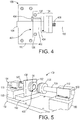
- FIG. 4 is a plan view
- FIG. 5 is a perspective depiction, of the device 100 in the region of the specimen mounting assembly 108.
- FIGS. 4 and 5 depict the device 100 in two different positions, but without a test sample affixed to the specimen mounting assembly 108.
- the specimen mount support 136 includes an aperture 400 through which the striker bar 104 extends during a test.
- the stationary specimen mount 132 also includes an aperture 402 through which the striker bar 104 extends during a test, where the aperture 400 is aligned with the aperture 402 to allow the passage of the striker bar 104 therethrough.
- FIG. 5 also depicts bearings 500 in the striker bar support 110 and the stretcher bar support 112 as described above.
- the stationary specimen mount may be removably or permanently mounted to the specimen mount support 136 using a fastener 406 such as one or more bolts or quick release fasteners.
- the movable specimen mount 134 may be removably or permanently mounted to the stretcher bar 106 using a fastener 408 such as one or more bolts or quick release fasteners.
- the stationary specimen mount 132 and the specimen mount support 136 may be fabricated from a single piece of material, such that the stationary specimen mount 132 is part of the specimen mount support 136.
- the stretcher bar 106 and the movable specimen mount 134 may be fabricated from a single piece of material, such that the movable specimen mount 134 is part of the stretcher bar 106.
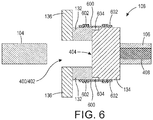
- FIG. 6 is a cross section in the region of the specimen mounting assembly 108 with a test sample 600 mounted or attached to the stationary specimen mount 132 and the movable specimen mount 134 using one or more fasteners 602 such as tape, epoxy, clamps, etc.
- the test sample 600 may be, for example, a rectangular strip of flexible material that is wrapped at least partially, or completely, around the circumference of both the stationary specimen mount 132 and the movable specimen mount 134. As depicted in FIG.
- the test sample 600 spans a recess 604 formed by one or both of the stationary specimen mount 132 and the movable specimen mount 134, such that a portion of the test sample 600 that spans the recess 604 is physically unsupported by stationary specimen mount 132 and the movable specimen mount 134.
- FIG. 6 depicts the specimen mounting assembly 108 prior to testing the test sample 600.
- the striker bar 104 is in the ready position, prior to striking the exposed face 404 of the movable specimen mount 134.
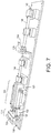
- the device 100 if FIG. 1 is first placed into the ready position.
- the plate 122 is moved toward the electromagnet 124 by pressurizing the one or more gas pistons 128 using the gas source 130 to extend an arm 152 of each gas piston 128 such that the plate 122 engages or physically contacts the electromagnet 124 as depicted in FIG. 7 .
- the electromagnet 124 is powered to maintain the plate 122 in the ready position, and the gas pistons 128 are depressurized to retract the arms 152 away from the plate 122. In this position, a potential energy is imparted to the spring 118 within the channel assembly 123.
- FIG. 7 depicts the movable specimen mount 134 positioned away from the stationary specimen mount 132, with no test specimen positioned within the specimen mounting assembly 108.
- a test sample 600 will be positioned within the specimen mounting assembly 108 as depicted in FIG. 6 .
- a test may be initiated by removing power from the electromagnet 124.
- the potential energy imparted to the spring 118 is released and converted to kinetic energy, which propels the striker bar 104 toward the stretcher bar 106.
- a second end of the striker bar 104 may extend into the aperture 400 through the specimen mount support 136, and into the aperture 402 through the stationary specimen mount 132, to physically contact the exposed face 404 of the movable specimen mount 134.
- FIG. 8 depicts the striker bar 104 just as it makes contact with the face 404 of the movable specimen mount 134.
- the force the striker bar 104 places on the exposed face 404 of the movable specimen mount 134 may be increased, for example, by using a spring 118 with a higher compression force spring (i.e., a stiffer spring) and/or by moving the electromagnet 124 further away from the channel assembly 123 such that the spring 118 is placed under a higher potential energy in the ready position.
- the base 102 may include one or more slots 154 that receive one or more adjustment bolts 156 through an electromagnet mount 158. The adjustment bolts 156 may be loosened for repositioning of the electromagnet mount 158 and the electromagnet 124 attached to the electromagnet mount 158, and then tightened to secure the electromagnet mount 158 and the electromagnet 124.
- data may be collected by any number of desired data collection devices such as the high-speed camera 140 and/or the accelerometer 142.
- the striker bar 104 contacts the movable specimen mount 134, a pressure wave is generated that propagates through the movable specimen mount 134 and into the stretcher bar 106.
- the pressure wave reaches the second end of the stretcher bar 106 (i.e., the end opposite the movable specimen mount 134), it reflects off the second end and propagates back through the stretcher bar 106 and the movable specimen mount 134.
- the pressure wave continues to propagate back and forth multiple times through the bars and the test sample, thereby creating a non-continuous stress and non-continuous strain within and through the test sample.
- the striker bar 104 and the stretcher bar 106 of device 100 may be designed to provide a more continuous stress on the test sample 600.
- the striker bar 104 and the stretcher bar 106 of the device 100 may be designed or selected to trap the pressure wave within the striker bar 104 after only one cycle of the pressure wave through the stretcher bar 106.
- a first pressure wave is generated that propagates through the stretcher bar 106 to the second (opposite) end of the stretcher bar 106, and reflects off the second end back to the first end.
- a second pressure wave is generated that propagates through the striker bar 104 to the first (opposite) end of the striker bar 104, and reflects off the first end back to the second end.
- the striker bar 104 During the traversal of the first pressure wave through the stretcher bar 106, the striker bar 104 remains in physical contact with the exposed face 404. Once the first pressure wave returns to the first end of the stretcher bar 106, the first pressure wave enters the striker bar 104. At this point, the striker bar 104 and the stretcher bar 106 separate as depicted in FIG. 9 such that there is a gap 900 between the second end of the striker bar 104 and the exposed face 404 of the movable specimen mount 134 such that, when the first pressure wave reflects off the first end of the striker bar 104 and returns to the second end of the striker bar 104, the first pressure wave cannot reenter the stretcher bar 106.
- the second pressure wave cannot enter the stretcher bar 106.
- the gap 900 remains until after the test of the test sample 600 is completed.
- the test sample 600 is subjected to the pressure wave fewer times, thereby imparting a more continuous stress to the test sample during testing.
- the Split-Hopkinson pressure bar has a wave that continues to propagate and reflect through the test device and the test specimen. This creates a step motion and a non-constant strain. For at least this reason, a Split-Hopkinson pressure bar measurement is valid only during the first step.
- a compression wave is generated in both bars 104, 106.
- the compression waves propagate out from the impact location.
- the compression waves reflect as a tension wave moving back toward the interface between the two bars 104, 106 (i.e., toward the test sample 600).
- the net result is that the tension wave and oncoming compression wave combine to produce zero net stress.
- the tension wave from the striker bar 104 and the tension wave from the stretcher bar 106 meet, the tension waves combine to form a net tensile stress.
- the tensile stress first forms at the interface between the two bars 104, 106.
- the interface cannot support tension, so the bars 104, 106 separate.
- the stretcher bar 106 is then left with a stress wave that continues propagating and reflecting through the stretcher bar 106.
- This wave transit causes the stretcher bar 106 to have an undesirable step-motion and thus a non-constant strain in the test specimen 600.
- the stretcher bar 106 is shorter than the striker bar 104, the reflected tension waves meet and combine within the striker bar 104. When this tension wave reaches the interface between the two bars 104, 106, the tension wave causes separation of the two bars 104, 106 thereby trapping the waves within the striker bar 104, leaving the stretcher bar 106 with a smooth linear motion.
- the striker bar 104 and the stretcher bar 106 may be manufactured from the same material, for example, stainless steel, aluminum, other metals or metal alloys, or another suitable material.
- pressure waves travel through both the striker bar 104 and the stretcher bar 106 at the same rate.
- the timing of contact between the striker bar 104 and the stretcher bar 106 i.e., "contact timing" may be selected by providing a striker bar 104 having a first length and a stretcher bar 106 (including the movable specimen mount 134) having a second length, where the first length is longer than the second length.
- the first pressure wave traverses the stretcher bar 106 and enters the striker bar 104 before the second wave traverses the striker bar 104 because the second wave in the striker bar 104 has a longer distance to travel.
- striker bar 104 and stretcher bar 106 separate to form the gap 900.
- the striker bar 104 may be manufactured from a first material and the stretcher bar 106 may be manufactured from a second material, where the first material propagates a pressure wave at a slower rate or slower speed than the second material.
- the striker bar 104 and the stretcher bar 106 may have the same length and the contact timing is controlled by the materials from which the bars are formed.
- the striker bar 104 may be formed from brass while the stretcher bar 106 is formed from steel, where the wave speed in steel is approximately 1.7 times that of brass.
- the contact timing itself may thus be similar to that as described above, such that the first and second pressure waves are trapped within the striker bar 104 when the two bars 104, 106 separate and the gap 900 occurs.
- the materials selected such that the striker bar 104 and the stretcher bar 106 do not deform on impact, or so that any error in measurement of the sample 600 resulting from deformation is within acceptable tolerances.
- FIG. 10 is a flow chart depicting an exemplary method 1000 for testing or measuring a test sample according to an embodiment of the present teachings. It will be understood that the described method is an example method. When implemented, an method according to the present teachings may include fewer or additional processing stages than those described and/or depicted, and the described processing stages may be implemented in a different order than described herein. In addition, the method 1000 may proceed by operation of one or more portions of the apparatus of FIGS. 1-9 , 11, and 12 , and is thus described by reference thereto. However, it will be appreciated that the method 1000 is not limited to any particular structure unless otherwise expressly stated.
- test samples may be prepared for measurement as depicted at 1002.
- the test sample may be an elastic material, for example, a silicone or other polymer, or the test sample may be a solid such as a ceramic, a metal, a metal alloy, a natural or synthetic composite, etc.
- a sheet of test material may be prepared, for example, by dispensing a liquid or gel to a uniform or non-uniform thickness.
- the test material may be cured using thermal processing, ultraviolet light, or another suitable process.
- the test material may be formed, molded, cut, etc., into a desirable shape for testing.
- a sheet of test material may be sectioned into a plurality of test samples, such as a plurality of rectangular strips.
- a solid material may be, for example, pressed or stamped into a sheet, or drawn into a wire, for testing.
- a test sample may include a single layer of material, or two or more layers of one or more materials.
- the test sample may be prepared by forming one or more rectangular strips of a test material.
- FIG. 11 is an exploded magnified cross section of part of a specimen mounting assembly 108, and depicts a test sample 1100.
- the cross section of FIG. 11 is a section through a width of the test sample 1100, and the test sample 1100 may extend around a circumference of both the stationary specimen mount 132 and the movable specimen mount 134 partially or completely.
- the test sample 1100 may include a test material 1102 as well as a support material such as an epoxy, another synthetic or natural adhesive, or other support material adhered to two or more edges of the test material 1102 to provide attachment strips 1104.
- Tensile adhesion of the attachment strips 1104 to the test material 1102 should exceed the tensile stress at which the test material 1102 fails to prevent separation of the attachment strips 1104 from the test material 1102 during the test or measurement. Further, tensile strength of the attachment strips 1104 should exceed the tensile strength of the test material 1102 to prevent failure of the attachment strips 1104 prior to failure of the test material 1102.
- the attachment strips 1104 are sized and configured to fit within test sample grooves 1106 formed within and around the circumference of the stationary specimen mount 132 and the movable specimen mount 134. The stationary specimen mount 132 thereby receives a first portion of the test sample 1100 and maintains the first portion of the test sample in a fixed position during the test or measurement.
- preparation of the test sample 1100 may include coating the test material 1102 with a speckle pattern 1108 for use with, for example, digital image correlation.
- the speckle pattern 1108 may include, for example, a light-reflective polymer, a metal flake such as a silver flake, or another light-reflective material.
- the test sample is mounted to the specimen mounting assembly. This may include, for example, positioning the attachment strips 1104 within the test sample grooves 1106 as depicted in FIG. 12 .
- the test sample 1100 may be attached to the specimen mounting assembly 108 using one or more fasteners 1200, such as one or more adhesives, tape strips, epoxies, or other fastener 1200.
- the test material 1102 spans the recess 604 formed by one or both of the stationary specimen mount 132 and the movable specimen mount 134, such that at least a portion of the test material 1102 spans the recess 604 and is physically unsupported by stationary specimen mount 132 and the movable specimen mount 134.
- the specimen mounting assembly 108 depicted and described above is merely one design of mounting assembly, and others are contemplated.
- a method may include attaching the test sample to the specimen mounting assembly (or subassembly) at a location that is remote from the remainder of the device 100, and then the specimen mounting assembly may be subsequently attached to the remainder of the device 100 as depicted at 1006.
- the drive assembly 114 may be moved from a resting or idle position to a cocked or ready position as depicted at 1008.
- this may include filling the gas pistons 128 with gas from the gas source 130 to extend the arms 152, thereby moving the plate 122 into position against the electromagnet 124.
- the plate 122 is held against the electromagnet 124 using magnetism, which maintains the drive assembly 114, including the spring 118, in the ready position.
- the drive assembly 114 depicted and described above is merely one possible drive assembly, and other electrical, mechanical, electromechanical, pneumatic, and chemical drive assemblies are contemplated.
- the drive assembly 114 After placing the drive assembly 114 into the ready position, the drive assembly 114 is released or fired to initiate a test or measurement.
- power may be removed from the electromagnet 124, thereby releasing the plate 122 and the spring 118.
- the drive assembly 114 thereby propels the stretcher bar 106 toward the striker bar 104 using the force applied by the spring 118 as depicted at 1012.
- the striker bar 104 extends through the aperture 400 in the specimen mount support 136 and the aperture 402 in the stationary specimen mount 132 to impact the exposed face 404 of the movable specimen mount 134.
- the effects of the tensile stress may be measured as depicted at 1016 using, for example, a high-speed camera 140, an accelerometer 142, or another measurement technique.
- images from the high-speed camera 140 may capture the specimen 600, and particularly the speckle pattern 1108.
- Digital image correlation (DIC) may be used to calculate strain within the specimen 600.
- the high-speed video frames may be post processed using particle image velocimetry (PIV) techniques to allow tracking of, for example, the speckle pattern 1108 and calculation of strain of the sample 600.
- PAV particle image velocimetry
- an embodiment of the present teachings may include a device or apparatus for measuring dynamic stress/strain response of ductile materials, elastic materials, or other materials.
- a device in accordance with the present teachings may include only a striker and a stretcher bar.
- a pressure wave requires a longer time to travel through the striker bar than the stretcher bar, for example, by forming the striker bar to have a longer length than the stretcher bar or by forming the striker bar that propagates the pressure wave at a slower rate than the striker bar.
- the two bars stay in contact long enough for the pressure wave to reflect off the far end of the stretcher and run back into the striker.
- the bars separate leaving the stretcher bar with smooth forward motion until the specimen fails.
- Servo-hydraulic test frames work well at low strain rates but are unable to provide high stain rate loading.
- the device 100 may provide strain rate loading of above 2 strains per second, for example, in the range of about 100 to about 2500 strains per second. While the Split-Hopkinson pressure bar works well with brittle materials, it is not able to provide a constant strain rate over a large distance and, for at least this reason, is not appropriate for testing highly ductile materials to the point of failure.
- the numerical values as stated for the parameter can take on negative values.
- the example value of range stated as "less than 10" can assume negative values, e.g. - 1, -2, -3, -10, -20, -30, etc.
- one or more of the acts depicted herein may be carried out in one or more separate acts and/or phases.
- the terms “including,” “includes,” “having,” “has,” “with,” or variants thereof are used in either the detailed description and the claims, such terms are intended to be inclusive in a manner similar to the term “comprising.”
- the term “at least one of” is used to mean one or more of the listed items can be selected.
- the term “on” used with respect to two materials, one “on” the other means at least some contact between the materials, while “over” means the materials are in proximity, but possibly with one or more additional intervening materials such that contact is possible but not required.
- Terms of relative position as used in this application are defined based on a plane parallel to the conventional plane or working surface of a workpiece, regardless of the orientation of the workpiece.
- the term “horizontal” or “lateral” as used in this application is defined as a plane parallel to the conventional plane or working surface of a workpiece, regardless of the orientation of the workpiece.
- the term “vertical” refers to a direction perpendicular to the horizontal. Terms such as “on,” “side” (as in “sidewall”), “higher,” “lower,” “over,” “top,” and “under” are defined with respect to the conventional plane or working surface being on the top surface of the workpiece, regardless of the orientation of the workpiece.
Landscapes
- Physics & Mathematics (AREA)
- Health & Medical Sciences (AREA)
- Life Sciences & Earth Sciences (AREA)
- Chemical & Material Sciences (AREA)
- Analytical Chemistry (AREA)
- Biochemistry (AREA)
- General Health & Medical Sciences (AREA)
- General Physics & Mathematics (AREA)
- Immunology (AREA)
- Pathology (AREA)
- Investigating Strength Of Materials By Application Of Mechanical Stress (AREA)
Applications Claiming Priority (1)
| Application Number | Priority Date | Filing Date | Title |
|---|---|---|---|
| US15/211,891 US10215674B2 (en) | 2016-07-15 | 2016-07-15 | Device for measuring the dynamic stress/strain response of ductile materials |
Publications (2)
| Publication Number | Publication Date |
|---|---|
| EP3270137A1 EP3270137A1 (en) | 2018-01-17 |
| EP3270137B1 true EP3270137B1 (en) | 2020-04-01 |
Family
ID=59315501
Family Applications (1)
| Application Number | Title | Priority Date | Filing Date |
|---|---|---|---|
| EP17180769.6A Active EP3270137B1 (en) | 2016-07-15 | 2017-07-11 | Device for measuring the dynamic stress/strain response of ductile materials |
Country Status (8)
| Country | Link |
|---|---|
| US (1) | US10215674B2 (enExample) |
| EP (1) | EP3270137B1 (enExample) |
| JP (1) | JP7002867B2 (enExample) |
| KR (1) | KR102341759B1 (enExample) |
| CN (1) | CN107621418B (enExample) |
| AU (1) | AU2017203538B2 (enExample) |
| BR (1) | BR102017014735B1 (enExample) |
| CA (1) | CA2971307C (enExample) |
Cited By (1)
| Publication number | Priority date | Publication date | Assignee | Title |
|---|---|---|---|---|
| CN111638118A (zh) * | 2020-07-09 | 2020-09-08 | 河海大学 | 测试混凝土受定量应变冲击后内部裂纹扩展的装置及方法 |
Families Citing this family (37)
| Publication number | Priority date | Publication date | Assignee | Title |
|---|---|---|---|---|
| US10481057B1 (en) * | 2016-12-01 | 2019-11-19 | National Technology & Engineering Solutions Of Sandia, Llc | Mechanical testing equipment for material characterization |
| CN108548735B (zh) * | 2018-05-23 | 2024-04-16 | 东北大学 | 一种霍普金森压杆子弹电磁回收装置 |
| CN109342564A (zh) * | 2018-11-12 | 2019-02-15 | 北京工业大学 | 一种用于研究高温下应力波在节理岩体中传播特性的试验装置 |
| CN109668801B (zh) * | 2019-01-07 | 2023-12-22 | 中国人民解放军陆军工程大学 | 一种基于数控驱动的高低温同步耦合Hopkinson压杆试验系统 |
| CN109708971A (zh) * | 2019-01-16 | 2019-05-03 | 浙江大学 | 一种霍普金森拉压一体试验装置 |
| CN110057663B (zh) * | 2019-02-28 | 2024-07-16 | 西南交通大学 | 电磁式霍普金森扭杆夹紧及释放装置 |
| CN110220775B (zh) * | 2019-06-21 | 2020-03-27 | 西南交通大学 | 一种基于轻气炮冲击加载下样品透射率的测量装置 |
| CN111665152A (zh) * | 2019-08-22 | 2020-09-15 | 西北工业大学 | 材料动态压缩循环加载装置及其方法 |
| CN110411869B (zh) * | 2019-09-02 | 2024-04-30 | 哈尔滨市黎明锅炉容器封头有限公司 | 液压气动中应变率拉伸试验装置及方法 |
| CN113049358A (zh) * | 2019-12-26 | 2021-06-29 | 有研工程技术研究院有限公司 | 一种金属材料动态断裂性能的表征方法 |
| KR102348742B1 (ko) * | 2020-03-04 | 2022-01-07 | (주)플렉시고 | 플렉시블 소재의 내구성 평가용 롤링장치 및 평가시스템 |
| CN111307573A (zh) * | 2020-04-12 | 2020-06-19 | 北京工业大学 | 一种基于磁悬浮技术研究应力波在一维岩石杆中传播特性的试验装置 |
| TWI724897B (zh) | 2020-05-14 | 2021-04-11 | 財團法人工業技術研究院 | 應變量測方法及應變量測裝置 |
| CN111855343B (zh) * | 2020-06-28 | 2023-01-17 | 东南大学 | 一种岩石节理动态力学特性及其波传播规律室内实验装置和方法 |
| CN111879603B (zh) * | 2020-09-09 | 2021-10-26 | 中南大学 | 一种复合材料板材的空气炮高速冲击测试工装及其应用方法 |
| CN112198046B (zh) * | 2020-09-28 | 2022-02-22 | 北京理工大学 | 一种用于shpb测试的加载杆自动组装装置 |
| CN112539992B (zh) * | 2020-12-02 | 2021-10-29 | 山东科技大学 | 霍普金森压杆实验多级脉冲加载装置及其实验方法 |
| CN112504875B (zh) * | 2020-12-10 | 2025-04-25 | 长安大学 | 基于shpb系统的岩石动态抗折试验装置及其试验方法 |
| CN112857965B (zh) * | 2021-01-08 | 2022-02-22 | 北京理工大学 | 一种shpb测试用高温加热系统 |
| CN113008658B (zh) * | 2021-02-02 | 2024-05-03 | 广州城建职业学院 | 一种基于双轴shpb实验的二波分解自平衡支撑装置 |
| CN112964540B (zh) * | 2021-02-10 | 2024-09-10 | 江西理工大学 | 高水压和高地应力耦合下岩石动力性能测试装置及方法 |
| CN113551985A (zh) * | 2021-07-22 | 2021-10-26 | 辽宁科技大学 | 一种基于霍普金森压杆试验系统的三向高速摄影装置 |
| CN113405928B (zh) * | 2021-08-19 | 2021-11-09 | 煤炭科学研究总院 | 冲击弹头和具有它的冲击试验设备 |
| CN113640118B (zh) * | 2021-08-24 | 2024-02-20 | 哈尔滨工业大学 | 材料原位动态拉伸加载试验装置 |
| CN114047060B (zh) * | 2021-09-03 | 2023-11-03 | 北京理工大学 | 用于爆炸焊接界面动态压缩拉伸力学性能测试的试样组件 |
| IT202100030854A1 (it) * | 2022-02-04 | 2023-08-04 | Univ Politecnica Delle Marche | Apparato per l'esecuzione di prove dinamiche su materiali a velocita' di deformazione intermedia |
| CN114965013A (zh) * | 2022-05-15 | 2022-08-30 | 西北工业大学 | 一种产生梯形应力波的电磁式应力波发生器及方法 |
| CN115184141B (zh) * | 2022-06-27 | 2024-06-07 | 武汉理工大学 | 基于dic的钢筋受压变形测量方法 |
| CN115308058A (zh) * | 2022-10-11 | 2022-11-08 | 中国矿业大学(北京) | 地下工程支护体系高应变率动力学试验与评价系统及方法 |
| CN115753339B (zh) * | 2022-11-16 | 2025-07-04 | 天津理工大学 | 用于霍普金森拉伸测试的应变调控装置及其使用方法 |
| CN116448598B (zh) * | 2023-03-09 | 2025-12-09 | 北京理工大学 | 一种三轴霍普金森杆冲击试验的加载控制装置与方法 |
| US20250027837A1 (en) * | 2023-07-19 | 2025-01-23 | Raytheon Company | Air gun shock test apparatus |
| CN117232950B (zh) * | 2023-07-29 | 2025-10-28 | 西北工业大学 | 可测量材料宽应变率力学性能的实验装置及实验方法 |
| CN116818567B (zh) * | 2023-08-30 | 2023-11-14 | 北京建筑大学 | 一种脆性固体材料的动力冲击破坏力学性能评价方法 |
| KR102642062B1 (ko) * | 2023-10-17 | 2024-03-04 | 국방과학연구소 | 충돌체 특성 시험 장치 |
| CN119375067B (zh) * | 2024-11-07 | 2025-11-18 | 天津大学 | 一种动态压杆冲击疲劳测试装置 |
| CN120176499B (zh) * | 2025-05-21 | 2025-07-25 | 内蒙古科技大学 | 一种用于霍普金森杆实验的子弹回收推杆装置 |
Family Cites Families (30)
| Publication number | Priority date | Publication date | Assignee | Title |
|---|---|---|---|---|
| JPH0725675Y2 (ja) * | 1989-07-31 | 1995-06-07 | 株式会社島津製作所 | 引張衝撃試験機 |
| US6109093A (en) | 1996-12-12 | 2000-08-29 | European Community | Split Hopkinson bar testing apparatus |
| EP0849583A1 (en) * | 1996-12-12 | 1998-06-24 | European Community | Split Hopkinson bar testing apparatus |
| US7024922B1 (en) | 1999-07-02 | 2006-04-11 | Sri Sports Limited | Viscoelastic characteristic value-measuring apparatus and method of measuring viscoelastic characteristic value |
| JP3485841B2 (ja) * | 1999-07-02 | 2004-01-13 | 紀壽 中川 | 粘弾性特性値測定装置及び粘弾性特性値測定方法 |
| US6848321B2 (en) | 2001-10-17 | 2005-02-01 | The Boeing Company | Bond strength measurement system using shock loads |
| JP3938757B2 (ja) * | 2002-04-08 | 2007-06-27 | 新日本製鐵株式会社 | 高速変形時の引張又は圧縮応力の精密計測方法及び装置 |
| US7516680B2 (en) | 2003-07-30 | 2009-04-14 | The Boeing Company | Strain energy shuttle apparatus and method |
| US7392708B2 (en) | 2005-05-06 | 2008-07-01 | The Boeing Company | Apparatus and method of measuring shear strain of thick adhesive bondlines |
| US7159470B2 (en) | 2005-05-20 | 2007-01-09 | The Boeing Company | Systems and methods of measuring residual stress in metallic materials |
| US7591168B2 (en) * | 2007-02-02 | 2009-09-22 | Sony Ericsson Mobile Communications Ab | Test equipment system and method for testing a component |
| JP4830913B2 (ja) * | 2007-03-05 | 2011-12-07 | 株式会社Ihi | 動的引張試験方法及び装置 |
| US8250928B2 (en) | 2008-07-09 | 2012-08-28 | The Boeing Company | Measurement of strain in an adhesively bonded joint including magnetostrictive material |
| JP5161168B2 (ja) * | 2009-08-05 | 2013-03-13 | 株式会社神戸製鋼所 | 衝撃試験装置 |
| US8527218B2 (en) | 2009-11-18 | 2013-09-03 | The Boeing Company | Strength measurement for bond lines |
| US8645086B1 (en) | 2010-09-18 | 2014-02-04 | The Boeing Company | Stress function calibration method |
| CN102135480B (zh) * | 2010-12-17 | 2013-06-12 | 北京理工大学 | 微型试件冲击加载与动态力学性能测量系统及方法 |
| KR20130034321A (ko) * | 2011-09-28 | 2013-04-05 | 한국건설기술연구원 | Shtb를 이용한 콘크리트 인장 시험 장치 및 방법 |
| US9063032B2 (en) | 2012-04-06 | 2015-06-23 | The Boeing Company | Signal monitoring system for monitoring strain applied to a composite component |
| CN103091159B (zh) * | 2013-02-05 | 2014-08-27 | 中国人民解放军陆军军官学院 | 新型分离式霍普金森拉杆装置 |
| CN103207122B (zh) * | 2013-04-15 | 2015-08-05 | 北京理工大学 | 具有预加载的微型动态拉压实验系统 |
| CN103353425B (zh) * | 2013-06-17 | 2015-06-17 | 宁波大学 | 一种冲击拉伸下试件中空穴演化观测试验方法 |
| US9261444B1 (en) | 2013-07-30 | 2016-02-16 | The Boeing Company | Apparatus, system, and method for in situ strength testing of a bonded joint |
| CN203643279U (zh) | 2013-12-09 | 2014-06-11 | 北京有色金属研究总院 | 一种材料动态剪切性能的测量装置 |
| US9863859B2 (en) * | 2014-04-23 | 2018-01-09 | Mississippi State University Research And Technology Corporation | Serpentine load monitoring apparatus |
| GB2534679B (en) * | 2014-12-22 | 2017-01-18 | Rolls Royce Plc | An output member |
| CN104678853B (zh) * | 2015-01-30 | 2017-09-26 | 西北工业大学 | 基于电磁力加载的霍普金森压杆实验设备控制系统 |
| CN104677760B (zh) * | 2015-01-30 | 2017-02-22 | 西北工业大学 | 双轴霍普金森压杆和拉杆实验入射波等效加载的实现方法 |
| CN105424470A (zh) * | 2015-11-18 | 2016-03-23 | 太原理工大学 | 一种分离式霍普金森拉杆试件的夹持装置及实验方法 |
| CN105571961B (zh) * | 2015-12-18 | 2018-05-15 | 西北工业大学 | 电磁感应式霍普金森拉压杆加载装置及实验方法 |
-
2016
- 2016-07-15 US US15/211,891 patent/US10215674B2/en active Active
-
2017
- 2017-05-26 AU AU2017203538A patent/AU2017203538B2/en active Active
- 2017-06-20 CA CA2971307A patent/CA2971307C/en active Active
- 2017-07-05 JP JP2017132122A patent/JP7002867B2/ja active Active
- 2017-07-07 BR BR102017014735-5A patent/BR102017014735B1/pt active IP Right Grant
- 2017-07-11 EP EP17180769.6A patent/EP3270137B1/en active Active
- 2017-07-14 KR KR1020170089754A patent/KR102341759B1/ko active Active
- 2017-07-14 CN CN201710578668.8A patent/CN107621418B/zh active Active
Non-Patent Citations (1)
| Title |
|---|
| None * |
Cited By (2)
| Publication number | Priority date | Publication date | Assignee | Title |
|---|---|---|---|---|
| CN111638118A (zh) * | 2020-07-09 | 2020-09-08 | 河海大学 | 测试混凝土受定量应变冲击后内部裂纹扩展的装置及方法 |
| CN111638118B (zh) * | 2020-07-09 | 2022-02-11 | 河海大学 | 测试混凝土受定量应变冲击后内部裂纹扩展的装置及方法 |
Also Published As
| Publication number | Publication date |
|---|---|
| AU2017203538A1 (en) | 2018-02-01 |
| CN107621418B (zh) | 2021-09-17 |
| CA2971307C (en) | 2021-07-13 |
| KR20180008344A (ko) | 2018-01-24 |
| BR102017014735B1 (pt) | 2023-01-10 |
| KR102341759B1 (ko) | 2021-12-21 |
| CA2971307A1 (en) | 2018-01-15 |
| JP2018048998A (ja) | 2018-03-29 |
| CN107621418A (zh) | 2018-01-23 |
| EP3270137A1 (en) | 2018-01-17 |
| BR102017014735A2 (pt) | 2018-03-20 |
| JP7002867B2 (ja) | 2022-01-20 |
| AU2017203538B2 (en) | 2021-09-16 |
| US10215674B2 (en) | 2019-02-26 |
| US20180017475A1 (en) | 2018-01-18 |
Similar Documents
| Publication | Publication Date | Title |
|---|---|---|
| EP3270137B1 (en) | Device for measuring the dynamic stress/strain response of ductile materials | |
| CN103207122B (zh) | 具有预加载的微型动态拉压实验系统 | |
| CN1033716C (zh) | 用于发电机定子槽楔紧固度的冲击试验的装置及方法 | |
| JP6573828B2 (ja) | 高周波での疲労亀裂の非伝播しきい値を決定する方法 | |
| CN101571467B (zh) | 薄膜材料动态弯曲疲劳性能测试系统及测试方法 | |
| CN103983307B (zh) | 一种可变冲击参数的小质量冲击试验测试系统 | |
| CN102087186B (zh) | 微动疲劳实验平台 | |
| JP2008539421A (ja) | マイクロ衝撃試験装置 | |
| CN203148798U (zh) | 具有预加载的微型动态拉压实验系统 | |
| CN117890199A (zh) | 一种用于弹性薄片微小样品应变状态性能测试的弯曲夹具 | |
| CN105466768A (zh) | 一种尺寸可调的预紧力落锤式冲击试验机板状试件夹具 | |
| CN114061872A (zh) | 一种三维高精度标定系统及方法 | |
| JPS63250548A (ja) | 棒材又は板材の損失係数、動弾性係数、動せん断弾性係数及び動ポアソン比の測定方法並びに測定装置 | |
| CN118329670B (zh) | 一种水利工程施工质量检测设备 | |
| CN109990999A (zh) | 下置式驱动压电高频疲劳试验机 | |
| CN114383939A (zh) | 一种检测材料动态力学性能的装置、试样及方法 | |
| CN210036474U (zh) | 一种基于光栅测长的线纹尺检定装置 | |
| CN114894358B (zh) | 一种后坐力间接测试装置及测试方法 | |
| RU58708U1 (ru) | Устройство для микромеханических испытаний | |
| CN204330509U (zh) | 压电驱动型高频疲劳试验机 | |
| CN107433258B (zh) | 无铁芯直线电机谐振激振器 | |
| CN206960417U (zh) | 固定装置和检测设备 | |
| CN108180988B (zh) | 正阶跃加速度激励装置 | |
| Friend et al. | A traveling-wave linear piezoelectric actuator with enclosed piezoelectric elements–the “Scream” actuator | |
| Kimberley et al. | A hybrid experimental/numerical investigation of the response of multilayered MEMS devices to dynamic loading |
Legal Events
| Date | Code | Title | Description |
|---|---|---|---|
| PUAI | Public reference made under article 153(3) epc to a published international application that has entered the european phase |
Free format text: ORIGINAL CODE: 0009012 |
|
| STAA | Information on the status of an ep patent application or granted ep patent |
Free format text: STATUS: REQUEST FOR EXAMINATION WAS MADE |
|
| 17P | Request for examination filed |
Effective date: 20170711 |
|
| AK | Designated contracting states |
Kind code of ref document: A1 Designated state(s): AL AT BE BG CH CY CZ DE DK EE ES FI FR GB GR HR HU IE IS IT LI LT LU LV MC MK MT NL NO PL PT RO RS SE SI SK SM TR |
|
| AX | Request for extension of the european patent |
Extension state: BA ME |
|
| GRAP | Despatch of communication of intention to grant a patent |
Free format text: ORIGINAL CODE: EPIDOSNIGR1 |
|
| STAA | Information on the status of an ep patent application or granted ep patent |
Free format text: STATUS: GRANT OF PATENT IS INTENDED |
|
| INTG | Intention to grant announced |
Effective date: 20181206 |
|
| GRAJ | Information related to disapproval of communication of intention to grant by the applicant or resumption of examination proceedings by the epo deleted |
Free format text: ORIGINAL CODE: EPIDOSDIGR1 |
|
| STAA | Information on the status of an ep patent application or granted ep patent |
Free format text: STATUS: REQUEST FOR EXAMINATION WAS MADE |
|
| INTC | Intention to grant announced (deleted) | ||
| STAA | Information on the status of an ep patent application or granted ep patent |
Free format text: STATUS: EXAMINATION IS IN PROGRESS |
|
| 17Q | First examination report despatched |
Effective date: 20190612 |
|
| GRAP | Despatch of communication of intention to grant a patent |
Free format text: ORIGINAL CODE: EPIDOSNIGR1 |
|
| STAA | Information on the status of an ep patent application or granted ep patent |
Free format text: STATUS: GRANT OF PATENT IS INTENDED |
|
| INTG | Intention to grant announced |
Effective date: 20191016 |
|
| GRAS | Grant fee paid |
Free format text: ORIGINAL CODE: EPIDOSNIGR3 |
|
| GRAA | (expected) grant |
Free format text: ORIGINAL CODE: 0009210 |
|
| STAA | Information on the status of an ep patent application or granted ep patent |
Free format text: STATUS: THE PATENT HAS BEEN GRANTED |
|
| AK | Designated contracting states |
Kind code of ref document: B1 Designated state(s): AL AT BE BG CH CY CZ DE DK EE ES FI FR GB GR HR HU IE IS IT LI LT LU LV MC MK MT NL NO PL PT RO RS SE SI SK SM TR |
|
| REG | Reference to a national code |
Ref country code: GB Ref legal event code: FG4D |
|
| REG | Reference to a national code |
Ref country code: CH Ref legal event code: EP Ref country code: AT Ref legal event code: REF Ref document number: 1251994 Country of ref document: AT Kind code of ref document: T Effective date: 20200415 |
|
| REG | Reference to a national code |
Ref country code: DE Ref legal event code: R096 Ref document number: 602017013857 Country of ref document: DE |
|
| REG | Reference to a national code |
Ref country code: IE Ref legal event code: FG4D |
|
| PG25 | Lapsed in a contracting state [announced via postgrant information from national office to epo] |
Ref country code: BG Free format text: LAPSE BECAUSE OF FAILURE TO SUBMIT A TRANSLATION OF THE DESCRIPTION OR TO PAY THE FEE WITHIN THE PRESCRIBED TIME-LIMIT Effective date: 20200701 |
|
| REG | Reference to a national code |
Ref country code: NL Ref legal event code: MP Effective date: 20200401 |
|
| REG | Reference to a national code |
Ref country code: LT Ref legal event code: MG4D |
|
| PG25 | Lapsed in a contracting state [announced via postgrant information from national office to epo] |
Ref country code: PT Free format text: LAPSE BECAUSE OF FAILURE TO SUBMIT A TRANSLATION OF THE DESCRIPTION OR TO PAY THE FEE WITHIN THE PRESCRIBED TIME-LIMIT Effective date: 20200817 Ref country code: GR Free format text: LAPSE BECAUSE OF FAILURE TO SUBMIT A TRANSLATION OF THE DESCRIPTION OR TO PAY THE FEE WITHIN THE PRESCRIBED TIME-LIMIT Effective date: 20200702 Ref country code: FI Free format text: LAPSE BECAUSE OF FAILURE TO SUBMIT A TRANSLATION OF THE DESCRIPTION OR TO PAY THE FEE WITHIN THE PRESCRIBED TIME-LIMIT Effective date: 20200401 Ref country code: NO Free format text: LAPSE BECAUSE OF FAILURE TO SUBMIT A TRANSLATION OF THE DESCRIPTION OR TO PAY THE FEE WITHIN THE PRESCRIBED TIME-LIMIT Effective date: 20200701 Ref country code: SE Free format text: LAPSE BECAUSE OF FAILURE TO SUBMIT A TRANSLATION OF THE DESCRIPTION OR TO PAY THE FEE WITHIN THE PRESCRIBED TIME-LIMIT Effective date: 20200401 Ref country code: IS Free format text: LAPSE BECAUSE OF FAILURE TO SUBMIT A TRANSLATION OF THE DESCRIPTION OR TO PAY THE FEE WITHIN THE PRESCRIBED TIME-LIMIT Effective date: 20200801 Ref country code: CZ Free format text: LAPSE BECAUSE OF FAILURE TO SUBMIT A TRANSLATION OF THE DESCRIPTION OR TO PAY THE FEE WITHIN THE PRESCRIBED TIME-LIMIT Effective date: 20200401 Ref country code: NL Free format text: LAPSE BECAUSE OF FAILURE TO SUBMIT A TRANSLATION OF THE DESCRIPTION OR TO PAY THE FEE WITHIN THE PRESCRIBED TIME-LIMIT Effective date: 20200401 Ref country code: LT Free format text: LAPSE BECAUSE OF FAILURE TO SUBMIT A TRANSLATION OF THE DESCRIPTION OR TO PAY THE FEE WITHIN THE PRESCRIBED TIME-LIMIT Effective date: 20200401 |
|
| REG | Reference to a national code |
Ref country code: AT Ref legal event code: MK05 Ref document number: 1251994 Country of ref document: AT Kind code of ref document: T Effective date: 20200401 |
|
| PG25 | Lapsed in a contracting state [announced via postgrant information from national office to epo] |
Ref country code: HR Free format text: LAPSE BECAUSE OF FAILURE TO SUBMIT A TRANSLATION OF THE DESCRIPTION OR TO PAY THE FEE WITHIN THE PRESCRIBED TIME-LIMIT Effective date: 20200401 Ref country code: LV Free format text: LAPSE BECAUSE OF FAILURE TO SUBMIT A TRANSLATION OF THE DESCRIPTION OR TO PAY THE FEE WITHIN THE PRESCRIBED TIME-LIMIT Effective date: 20200401 Ref country code: RS Free format text: LAPSE BECAUSE OF FAILURE TO SUBMIT A TRANSLATION OF THE DESCRIPTION OR TO PAY THE FEE WITHIN THE PRESCRIBED TIME-LIMIT Effective date: 20200401 |
|
| PG25 | Lapsed in a contracting state [announced via postgrant information from national office to epo] |
Ref country code: AL Free format text: LAPSE BECAUSE OF FAILURE TO SUBMIT A TRANSLATION OF THE DESCRIPTION OR TO PAY THE FEE WITHIN THE PRESCRIBED TIME-LIMIT Effective date: 20200401 |
|
| REG | Reference to a national code |
Ref country code: DE Ref legal event code: R097 Ref document number: 602017013857 Country of ref document: DE |
|
| PG25 | Lapsed in a contracting state [announced via postgrant information from national office to epo] |
Ref country code: ES Free format text: LAPSE BECAUSE OF FAILURE TO SUBMIT A TRANSLATION OF THE DESCRIPTION OR TO PAY THE FEE WITHIN THE PRESCRIBED TIME-LIMIT Effective date: 20200401 Ref country code: AT Free format text: LAPSE BECAUSE OF FAILURE TO SUBMIT A TRANSLATION OF THE DESCRIPTION OR TO PAY THE FEE WITHIN THE PRESCRIBED TIME-LIMIT Effective date: 20200401 Ref country code: DK Free format text: LAPSE BECAUSE OF FAILURE TO SUBMIT A TRANSLATION OF THE DESCRIPTION OR TO PAY THE FEE WITHIN THE PRESCRIBED TIME-LIMIT Effective date: 20200401 Ref country code: IT Free format text: LAPSE BECAUSE OF FAILURE TO SUBMIT A TRANSLATION OF THE DESCRIPTION OR TO PAY THE FEE WITHIN THE PRESCRIBED TIME-LIMIT Effective date: 20200401 Ref country code: EE Free format text: LAPSE BECAUSE OF FAILURE TO SUBMIT A TRANSLATION OF THE DESCRIPTION OR TO PAY THE FEE WITHIN THE PRESCRIBED TIME-LIMIT Effective date: 20200401 Ref country code: SM Free format text: LAPSE BECAUSE OF FAILURE TO SUBMIT A TRANSLATION OF THE DESCRIPTION OR TO PAY THE FEE WITHIN THE PRESCRIBED TIME-LIMIT Effective date: 20200401 Ref country code: RO Free format text: LAPSE BECAUSE OF FAILURE TO SUBMIT A TRANSLATION OF THE DESCRIPTION OR TO PAY THE FEE WITHIN THE PRESCRIBED TIME-LIMIT Effective date: 20200401 |
|
| PLBE | No opposition filed within time limit |
Free format text: ORIGINAL CODE: 0009261 |
|
| STAA | Information on the status of an ep patent application or granted ep patent |
Free format text: STATUS: NO OPPOSITION FILED WITHIN TIME LIMIT |
|
| PG25 | Lapsed in a contracting state [announced via postgrant information from national office to epo] |
Ref country code: SK Free format text: LAPSE BECAUSE OF FAILURE TO SUBMIT A TRANSLATION OF THE DESCRIPTION OR TO PAY THE FEE WITHIN THE PRESCRIBED TIME-LIMIT Effective date: 20200401 Ref country code: MC Free format text: LAPSE BECAUSE OF FAILURE TO SUBMIT A TRANSLATION OF THE DESCRIPTION OR TO PAY THE FEE WITHIN THE PRESCRIBED TIME-LIMIT Effective date: 20200401 Ref country code: PL Free format text: LAPSE BECAUSE OF FAILURE TO SUBMIT A TRANSLATION OF THE DESCRIPTION OR TO PAY THE FEE WITHIN THE PRESCRIBED TIME-LIMIT Effective date: 20200401 |
|
| REG | Reference to a national code |
Ref country code: CH Ref legal event code: PL |
|
| 26N | No opposition filed |
Effective date: 20210112 |
|
| REG | Reference to a national code |
Ref country code: BE Ref legal event code: MM Effective date: 20200731 |
|
| PG25 | Lapsed in a contracting state [announced via postgrant information from national office to epo] |
Ref country code: LU Free format text: LAPSE BECAUSE OF NON-PAYMENT OF DUE FEES Effective date: 20200711 Ref country code: LI Free format text: LAPSE BECAUSE OF NON-PAYMENT OF DUE FEES Effective date: 20200731 Ref country code: CH Free format text: LAPSE BECAUSE OF NON-PAYMENT OF DUE FEES Effective date: 20200731 |
|
| PG25 | Lapsed in a contracting state [announced via postgrant information from national office to epo] |
Ref country code: SI Free format text: LAPSE BECAUSE OF FAILURE TO SUBMIT A TRANSLATION OF THE DESCRIPTION OR TO PAY THE FEE WITHIN THE PRESCRIBED TIME-LIMIT Effective date: 20200401 Ref country code: BE Free format text: LAPSE BECAUSE OF NON-PAYMENT OF DUE FEES Effective date: 20200731 |
|
| PG25 | Lapsed in a contracting state [announced via postgrant information from national office to epo] |
Ref country code: IE Free format text: LAPSE BECAUSE OF NON-PAYMENT OF DUE FEES Effective date: 20200711 |
|
| PG25 | Lapsed in a contracting state [announced via postgrant information from national office to epo] |
Ref country code: TR Free format text: LAPSE BECAUSE OF FAILURE TO SUBMIT A TRANSLATION OF THE DESCRIPTION OR TO PAY THE FEE WITHIN THE PRESCRIBED TIME-LIMIT Effective date: 20200401 Ref country code: MT Free format text: LAPSE BECAUSE OF FAILURE TO SUBMIT A TRANSLATION OF THE DESCRIPTION OR TO PAY THE FEE WITHIN THE PRESCRIBED TIME-LIMIT Effective date: 20200401 Ref country code: CY Free format text: LAPSE BECAUSE OF FAILURE TO SUBMIT A TRANSLATION OF THE DESCRIPTION OR TO PAY THE FEE WITHIN THE PRESCRIBED TIME-LIMIT Effective date: 20200401 |
|
| PG25 | Lapsed in a contracting state [announced via postgrant information from national office to epo] |
Ref country code: MK Free format text: LAPSE BECAUSE OF FAILURE TO SUBMIT A TRANSLATION OF THE DESCRIPTION OR TO PAY THE FEE WITHIN THE PRESCRIBED TIME-LIMIT Effective date: 20200401 |
|
| P01 | Opt-out of the competence of the unified patent court (upc) registered |
Effective date: 20230516 |
|
| PGFP | Annual fee paid to national office [announced via postgrant information from national office to epo] |
Ref country code: DE Payment date: 20250729 Year of fee payment: 9 |
|
| PGFP | Annual fee paid to national office [announced via postgrant information from national office to epo] |
Ref country code: GB Payment date: 20250728 Year of fee payment: 9 |
|
| PGFP | Annual fee paid to national office [announced via postgrant information from national office to epo] |
Ref country code: FR Payment date: 20250725 Year of fee payment: 9 |