EP3270137B1 - Device for measuring the dynamic stress/strain response of ductile materials - Google Patents
Device for measuring the dynamic stress/strain response of ductile materials Download PDFInfo
- Publication number
- EP3270137B1 EP3270137B1 EP17180769.6A EP17180769A EP3270137B1 EP 3270137 B1 EP3270137 B1 EP 3270137B1 EP 17180769 A EP17180769 A EP 17180769A EP 3270137 B1 EP3270137 B1 EP 3270137B1
- Authority
- EP
- European Patent Office
- Prior art keywords
- bar
- specimen mount
- striker bar
- striker
- test sample
- Prior art date
- Legal status (The legal status is an assumption and is not a legal conclusion. Google has not performed a legal analysis and makes no representation as to the accuracy of the status listed.)
- Active
Links
- 239000000463 material Substances 0.000 title claims description 76
- 230000004044 response Effects 0.000 title claims description 8
- 238000012360 testing method Methods 0.000 claims description 149
- 238000005259 measurement Methods 0.000 claims description 23
- 238000000034 method Methods 0.000 claims description 23
- 230000003116 impacting effect Effects 0.000 claims description 7
- 230000000694 effects Effects 0.000 claims description 5
- 230000033001 locomotion Effects 0.000 description 15
- 230000005540 biological transmission Effects 0.000 description 8
- 230000006835 compression Effects 0.000 description 6
- 238000007906 compression Methods 0.000 description 6
- 238000012545 processing Methods 0.000 description 5
- 238000010008 shearing Methods 0.000 description 5
- 238000013480 data collection Methods 0.000 description 4
- 239000013013 elastic material Substances 0.000 description 4
- 229910052751 metal Inorganic materials 0.000 description 4
- 239000002184 metal Substances 0.000 description 4
- 229920000642 polymer Polymers 0.000 description 4
- 230000008569 process Effects 0.000 description 4
- 239000004593 Epoxy Substances 0.000 description 3
- 229910000831 Steel Inorganic materials 0.000 description 3
- 238000005381 potential energy Methods 0.000 description 3
- 238000000926 separation method Methods 0.000 description 3
- 239000007787 solid Substances 0.000 description 3
- 239000010959 steel Substances 0.000 description 3
- 229910001369 Brass Inorganic materials 0.000 description 2
- XEEYBQQBJWHFJM-UHFFFAOYSA-N Iron Chemical compound [Fe] XEEYBQQBJWHFJM-UHFFFAOYSA-N 0.000 description 2
- 239000000853 adhesive Substances 0.000 description 2
- 230000001070 adhesive effect Effects 0.000 description 2
- 230000004075 alteration Effects 0.000 description 2
- 229910052782 aluminium Inorganic materials 0.000 description 2
- XAGFODPZIPBFFR-UHFFFAOYSA-N aluminium Chemical compound [Al] XAGFODPZIPBFFR-UHFFFAOYSA-N 0.000 description 2
- 230000000712 assembly Effects 0.000 description 2
- 238000000429 assembly Methods 0.000 description 2
- 239000010951 brass Substances 0.000 description 2
- 239000011248 coating agent Substances 0.000 description 2
- 238000000576 coating method Methods 0.000 description 2
- 238000013461 design Methods 0.000 description 2
- 239000003302 ferromagnetic material Substances 0.000 description 2
- 239000012530 fluid Substances 0.000 description 2
- -1 for example Substances 0.000 description 2
- 238000000691 measurement method Methods 0.000 description 2
- 229910001092 metal group alloy Inorganic materials 0.000 description 2
- 150000002739 metals Chemical class 0.000 description 2
- 238000000917 particle-image velocimetry Methods 0.000 description 2
- 230000000704 physical effect Effects 0.000 description 2
- 229920001296 polysiloxane Polymers 0.000 description 2
- 238000003825 pressing Methods 0.000 description 2
- 229910000640 Fe alloy Inorganic materials 0.000 description 1
- 244000043261 Hevea brasiliensis Species 0.000 description 1
- BQCADISMDOOEFD-UHFFFAOYSA-N Silver Chemical compound [Ag] BQCADISMDOOEFD-UHFFFAOYSA-N 0.000 description 1
- 239000004826 Synthetic adhesive Substances 0.000 description 1
- 239000006096 absorbing agent Substances 0.000 description 1
- 230000001133 acceleration Effects 0.000 description 1
- 230000004888 barrier function Effects 0.000 description 1
- 239000000227 bioadhesive Substances 0.000 description 1
- 238000004364 calculation method Methods 0.000 description 1
- 239000000919 ceramic Substances 0.000 description 1
- 238000004891 communication Methods 0.000 description 1
- 239000002131 composite material Substances 0.000 description 1
- 230000003247 decreasing effect Effects 0.000 description 1
- 230000001419 dependent effect Effects 0.000 description 1
- 229920001971 elastomer Polymers 0.000 description 1
- 239000000806 elastomer Substances 0.000 description 1
- 125000003700 epoxy group Chemical group 0.000 description 1
- 230000005284 excitation Effects 0.000 description 1
- 229910052742 iron Inorganic materials 0.000 description 1
- 239000010410 layer Substances 0.000 description 1
- 239000007788 liquid Substances 0.000 description 1
- 230000005389 magnetism Effects 0.000 description 1
- 238000004519 manufacturing process Methods 0.000 description 1
- 238000010297 mechanical methods and process Methods 0.000 description 1
- 238000012986 modification Methods 0.000 description 1
- 230000004048 modification Effects 0.000 description 1
- 238000012544 monitoring process Methods 0.000 description 1
- 229920003052 natural elastomer Polymers 0.000 description 1
- 229920001194 natural rubber Polymers 0.000 description 1
- 229920000647 polyepoxide Polymers 0.000 description 1
- 238000002360 preparation method Methods 0.000 description 1
- 238000003672 processing method Methods 0.000 description 1
- 230000001902 propagating effect Effects 0.000 description 1
- 238000004080 punching Methods 0.000 description 1
- 230000000284 resting effect Effects 0.000 description 1
- 230000035939 shock Effects 0.000 description 1
- 239000002356 single layer Substances 0.000 description 1
- 239000011343 solid material Substances 0.000 description 1
- 125000006850 spacer group Chemical group 0.000 description 1
- 239000010935 stainless steel Substances 0.000 description 1
- 229910001220 stainless steel Inorganic materials 0.000 description 1
- 239000000126 substance Substances 0.000 description 1
- 229920002994 synthetic fiber Polymers 0.000 description 1
Images


Classifications
-
- G—PHYSICS
- G01—MEASURING; TESTING
- G01N—INVESTIGATING OR ANALYSING MATERIALS BY DETERMINING THEIR CHEMICAL OR PHYSICAL PROPERTIES
- G01N3/00—Investigating strength properties of solid materials by application of mechanical stress
- G01N3/30—Investigating strength properties of solid materials by application of mechanical stress by applying a single impulsive force, e.g. by falling weight
- G01N3/307—Investigating strength properties of solid materials by application of mechanical stress by applying a single impulsive force, e.g. by falling weight generated by a compressed or tensile-stressed spring; generated by pneumatic or hydraulic means
-
- G—PHYSICS
- G01—MEASURING; TESTING
- G01N—INVESTIGATING OR ANALYSING MATERIALS BY DETERMINING THEIR CHEMICAL OR PHYSICAL PROPERTIES
- G01N3/00—Investigating strength properties of solid materials by application of mechanical stress
- G01N3/08—Investigating strength properties of solid materials by application of mechanical stress by applying steady tensile or compressive forces
-
- G—PHYSICS
- G01—MEASURING; TESTING
- G01N—INVESTIGATING OR ANALYSING MATERIALS BY DETERMINING THEIR CHEMICAL OR PHYSICAL PROPERTIES
- G01N3/00—Investigating strength properties of solid materials by application of mechanical stress
- G01N3/02—Details
-
- G—PHYSICS
- G01—MEASURING; TESTING
- G01N—INVESTIGATING OR ANALYSING MATERIALS BY DETERMINING THEIR CHEMICAL OR PHYSICAL PROPERTIES
- G01N3/00—Investigating strength properties of solid materials by application of mechanical stress
- G01N3/02—Details
- G01N3/04—Chucks
-
- G—PHYSICS
- G01—MEASURING; TESTING
- G01N—INVESTIGATING OR ANALYSING MATERIALS BY DETERMINING THEIR CHEMICAL OR PHYSICAL PROPERTIES
- G01N3/00—Investigating strength properties of solid materials by application of mechanical stress
- G01N3/30—Investigating strength properties of solid materials by application of mechanical stress by applying a single impulsive force, e.g. by falling weight
-
- G—PHYSICS
- G01—MEASURING; TESTING
- G01N—INVESTIGATING OR ANALYSING MATERIALS BY DETERMINING THEIR CHEMICAL OR PHYSICAL PROPERTIES
- G01N2203/00—Investigating strength properties of solid materials by application of mechanical stress
- G01N2203/0001—Type of application of the stress
- G01N2203/001—Impulsive
-
- G—PHYSICS
- G01—MEASURING; TESTING
- G01N—INVESTIGATING OR ANALYSING MATERIALS BY DETERMINING THEIR CHEMICAL OR PHYSICAL PROPERTIES
- G01N2203/00—Investigating strength properties of solid materials by application of mechanical stress
- G01N2203/0014—Type of force applied
- G01N2203/0016—Tensile or compressive
- G01N2203/0017—Tensile
-
- G—PHYSICS
- G01—MEASURING; TESTING
- G01N—INVESTIGATING OR ANALYSING MATERIALS BY DETERMINING THEIR CHEMICAL OR PHYSICAL PROPERTIES
- G01N2203/00—Investigating strength properties of solid materials by application of mechanical stress
- G01N2203/003—Generation of the force
- G01N2203/0032—Generation of the force using mechanical means
- G01N2203/0035—Spring
-
- G—PHYSICS
- G01—MEASURING; TESTING
- G01N—INVESTIGATING OR ANALYSING MATERIALS BY DETERMINING THEIR CHEMICAL OR PHYSICAL PROPERTIES
- G01N2203/00—Investigating strength properties of solid materials by application of mechanical stress
- G01N2203/003—Generation of the force
- G01N2203/0055—Generation of the force using mechanical waves, e.g. acoustic
-
- G—PHYSICS
- G01—MEASURING; TESTING
- G01N—INVESTIGATING OR ANALYSING MATERIALS BY DETERMINING THEIR CHEMICAL OR PHYSICAL PROPERTIES
- G01N2203/00—Investigating strength properties of solid materials by application of mechanical stress
- G01N2203/0058—Kind of property studied
- G01N2203/0092—Visco-elasticity, solidification, curing, cross-linking degree, vulcanisation or strength properties of semi-solid materials
- G01N2203/0094—Visco-elasticity
-
- G—PHYSICS
- G01—MEASURING; TESTING
- G01N—INVESTIGATING OR ANALYSING MATERIALS BY DETERMINING THEIR CHEMICAL OR PHYSICAL PROPERTIES
- G01N2203/00—Investigating strength properties of solid materials by application of mechanical stress
- G01N2203/0098—Tests specified by its name, e.g. Charpy, Brinnel, Mullen
-
- G—PHYSICS
- G01—MEASURING; TESTING
- G01N—INVESTIGATING OR ANALYSING MATERIALS BY DETERMINING THEIR CHEMICAL OR PHYSICAL PROPERTIES
- G01N2203/00—Investigating strength properties of solid materials by application of mechanical stress
- G01N2203/02—Details not specific for a particular testing method
- G01N2203/025—Geometry of the test
- G01N2203/0252—Monoaxial, i.e. the forces being applied along a single axis of the specimen
-
- G—PHYSICS
- G01—MEASURING; TESTING
- G01N—INVESTIGATING OR ANALYSING MATERIALS BY DETERMINING THEIR CHEMICAL OR PHYSICAL PROPERTIES
- G01N2203/00—Investigating strength properties of solid materials by application of mechanical stress
- G01N2203/02—Details not specific for a particular testing method
- G01N2203/026—Specifications of the specimen
- G01N2203/0262—Shape of the specimen
- G01N2203/0278—Thin specimens
-
- G—PHYSICS
- G01—MEASURING; TESTING
- G01N—INVESTIGATING OR ANALYSING MATERIALS BY DETERMINING THEIR CHEMICAL OR PHYSICAL PROPERTIES
- G01N2203/00—Investigating strength properties of solid materials by application of mechanical stress
- G01N2203/02—Details not specific for a particular testing method
- G01N2203/06—Indicating or recording means; Sensing means
- G01N2203/0641—Indicating or recording means; Sensing means using optical, X-ray, ultraviolet, infrared or similar detectors
- G01N2203/0647—Image analysis
-
- G—PHYSICS
- G01—MEASURING; TESTING
- G01N—INVESTIGATING OR ANALYSING MATERIALS BY DETERMINING THEIR CHEMICAL OR PHYSICAL PROPERTIES
- G01N2203/00—Investigating strength properties of solid materials by application of mechanical stress
- G01N2203/02—Details not specific for a particular testing method
- G01N2203/06—Indicating or recording means; Sensing means
- G01N2203/067—Parameter measured for estimating the property
- G01N2203/0676—Force, weight, load, energy, speed or acceleration
Definitions
- the present teachings relate to the field of materials metrology and, more particularly, to a device for measuring stress and strain characteristics of a flexible pliable material or another material.
- a Split-Hopkinson pressure bar may be used to test the dynamic stress-strain response of materials.
- a specimen or test sample is placed between, and physically contacts, an incident bar and a transmission bar.
- a stress wave, pressure wave, or incident wave is created using a striker bar.
- the incident wave propagates through the incident bar from the first end toward a second end that physically contacts the specimen.
- a first portion of the energy from the incident wave travels through the specimen while a second portion is reflected away from the specimen and back through the incident bar.
- the first portion of the wave travels through, stresses, and deforms the specimen, and is then transferred to the transmission bar that physically contacts the specimen. Movement of the transmission bar may be stopped by a momentum bar and a momentum trap.
- the Split-Hopkinson pressure bar subjects a test sample between the incident bar and the transmission bar to a compressive force as the incident wave travels through the test sample.
- the Split-Hopkinson pressure bar may thus test materials in tension, but does not function well for specimens that have a high strain to failure.
- testing of a specimen using the Split-Hopkinson pressure bar subjects the material to a non-constant strain rate as the incident wave propagates back and forth through the incident bar and the transmission bar.
- the Split-Hopkinson pressure bar thus provides a high strain rate but not a high strain.
- Other devices using servo-mechanical methods may provide high strain but not a high strain rate.
- a device that is suitable for measuring various characteristics such as tensile strength and failure stresses at a constant strain rate of various materials such as flexible, pliable, and ductile materials, as well as other materials, that provides both a high strain rate and high strain, would be a welcome addition to the art.
- CN 203643279 describes a device for measuring the dynamic shearing property of a material, and which belongs to the technical field of testers.
- a test sample slot is formed in one end of a test sample fixing support; a screw hole is formed in each of two sides of the test sample slot; a shearing test sample is locked in the test sample slot through fixing screws; a cuboid punching head is arranged at one end of a shearing impact pressing head; therefore, the material dynamic shearing property measurement device is assembled and is arranged between an incidence rod and a transmission rod of a separate type Hopkinson pressing rod; the dynamic shearing property of the material can be directly measured by a conventional elastic wave excitation mode and a stress wave signal collection and processing method.
- the apparatus comprises means for measuring an effect of the tensile stress on the test sample; a striker bar; a stretcher bar; a drive assembly configured to propel the striker bar toward the stretcher bar; a stationary specimen mount configured to receive a first portion of the test sample and to maintain the first portion of the test sample in a fixed position; and a movable specimen mount attached to a first end of the stretcher bar, the movable specimen mount configured to receive a second portion of the test sample.
- the striker bar is aligned with the stretcher bar and the striker bar is configured to impact with the movable specimen mount.
- the stretcher bar and the movable specimen mount are configured to move away from the stationary specimen mount from an impact of the striker bar with the movable specimen mount during a test or measurement of the test sample.
- the method comprises: (a) propelling the striker bar toward the stretcher bar; (b) impacting the movable specimen mount with the striker bar; (c) moving the movable specimen mount away from the stationary specimen mount resulting from the striker bar impacting the movable specimen mount; (d) applying the dynamic tensile stress and/or strain to the test sample attached to the stationary specimen mount and to the movable specimen mount resulting from the moving of the movable specimen mount away from the stationary specimen mount; and (e) measuring the effect of the tensile stress on the test sample.
- FIGS. It should be noted that some details of the FIGS. have been simplified and are drawn to facilitate understanding of the present teachings rather than to maintain strict structural accuracy, detail, and scale.
- the present teachings provide a method and structure for testing and/or obtaining performance data on a test specimen such as an elastic or non-elastic material sample.
- the method may include the dynamic measurement of tensile strength of the material sample over a relatively constant strain rate. While some conventional measurement techniques propagate a pressure wave back and forth multiple times through various device structures as well as the test specimen, which results in a non-constant stress/strain on the test specimen, a device or test structure of the present teachings may, in some embodiments, have a decreased pressure wave propagation through various device structures and the test sample, thereby resulting in more accurate stress and/or strain data.
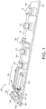
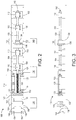
- FIG. 1 is a perspective depiction
- FIG. 2 is a plan view
- FIG. 3 is a side view, of a device or apparatus 100 for testing and/or measuring tensile characteristics, performance data, or other physical properties of a test sample.
- FIGS. 1-3 depict an exemplary structure, and that a measurement device in accordance with the present teachings may include other device substructures that are not depicted for simplicity, while various depicted device substructures may be removed or modified.
- the device 100 may include a base 102 to which other measurement device substructures are attached and/or mounted using one or more fasteners, for example, one or more screws, bolts, pegs, clips, clamps, adhesives, etc. (not individually depicted for simplicity).
- the measurement device 100 further includes a striker bar 104, a stretcher bar 106, and a specimen mounting assembly 108.
- the device 100 may further include one or more striker bar supports 110 attached to the base 102 that guide and support the striker bar 104, and allow axial movement of the striker bar 104 toward and away from the stretcher bar 106 during use.
- Each striker bar support 110 may include one or more bearings 500 ( FIG. 5 ), such as one or more bushings (for example, solid sleeve bushings or split bushings), roller bearings, or other low-friction supports, that support and allow low-friction axial movement of the striker bar 104.
- the device 100 may also include one or more stretcher bar supports 112 attached to the base 102 that guide and support the stretcher bar 106 and allow axial movement of the stretcher bar 106 away from the striker bar 104 during use.
- Each stretcher bar support 112 may include one or more bearings, such as one or more bushings (for example, solid sleeve bushings or split bushings), roller bearings, or other low-friction supports, that support and allow low-friction axial movement of the stretcher bar 106.
- the device 100 of FIGS. 1-3 further includes a drive assembly 114 and a release assembly 116.
- the drive assembly 114 is configured to propel the striker bar 104 toward the stretcher bar 106 using, for example, one or more springs, compressed gas, or another method.
- the force with which the drive assembly 114 propels the striker bar 104 may be adjustable, for example, to accommodate different test sample materials and test conditions.
- the release assembly 116 is configured to maintain or hold the striker bar 104 in a ready, engaged, or cocked position and to release the striker bar 104 to initiate a test or measurement (hereinafter, collectively, "test") of the test sample.
- test test or measurement
- the spring may be held under tension when the device 100 is in the ready position.
- a drive assembly 114 including a fast acting gas valve the gas may be pressurized within a canister when the device 100 is in the ready position.
- the drive assembly 114 and the release assembly 116, as well as other assemblies of the device 100 are contemplated.
- the drive assembly 114 of the device 100 of FIGS. 1-3 includes a spring 118 that encircles the striker bar 104 and a retainer 120 attached to a first end 119 of the spring 118.
- a second end 121 of the spring 118 may be secured to the striker bar 104 within a channel assembly 123, where at least a portion of the spring 118 and a portion of the striker bar 104 are positioned and/or enclosed within a channel of the channel assembly 123.
- the drive assembly 114 may further include a plate 122 adjacent to the retainer 120.
- the plate 122 may be manufactured to be or include a ferromagnetic material such as an iron, an iron alloy, or another ferromagnetic material.
- the plate 122 may be attached to a first end of the striker bar 104, and the first end of the striker bar 104 may extend through a hole in the retainer 120.
- the release assembly 116 may include an electromagnet 124 attached to a power source 126.
- the electromagnet 124 is positioned such that the plate 122 may be held in the ready position by the electromagnet 124 after retracting the plate 122.
- the device 100 may further include one or more retractors 128 to assist with retracting the drive assembly 114 from an idle position to the ready position.
- the retractors 128 retract the plate 122 away from the channel assembly 123 to position the plate 122, the spring 118, and the striker bar 104 into the ready position.
- the retractors 128 may include one or more electric, gas, or hydraulic pistons 128 in fluid communication with a power, gas, or hydraulic fluid source 130.
- the specimen mounting assembly 108 includes a stationary specimen mount 132 and a movable specimen mount 134, each of which receives the specimen (i.e., the test sample) during a test.
- the stationary specimen mount 132 may be attached to a specimen mount support 136, while the movable specimen mount 134 is attached to a first end of the stretcher bar 106.
- the specimen mounting assembly is described in more detail below with reference to FIGS. 4 and 5 .
- One or more data collection devices may be used to collect data during testing.
- the data collection devices may include, for example, a high-speed camera 140 focused, for example, on the specimen mounting assembly 108 during testing.
- Data collection may also including an accelerometer 142 positioned on a second end of the stretcher bar 106 or at another location suitable for monitoring a force and/or an acceleration of the stretcher bar 106 during testing.
- the device 100 is assembled such that the striker bar 104 is targeted to be in axial alignment with the stretcher bar 106. In other words, an axis of the striker bar 104 is aligned with an axis of the stretcher bar 106.
- any number of spacers 150 may be positioned between the base 102 and one or more of the channel assembly 123, the striker bar supports 110, the specimen mount support 136, the stretcher bar supports 112, and/or at other locations as necessary or desired.
- the base 102 may be a table or a surface secured to a table or other mounting surface. For most accurate test results, unintentional movement such as vibration of the device 100 may be minimized during testing. This includes vibrations and other unintentional movement resulting from external sources such as other equipment.
- Components and subassemblies of the device 100 may be manufactured from various materials such as polymers, metals such as steel or aluminum, and/or other natural or synthetic materials.
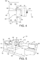
- FIG. 4 is a plan view
- FIG. 5 is a perspective depiction, of the device 100 in the region of the specimen mounting assembly 108.
- FIGS. 4 and 5 depict the device 100 in two different positions, but without a test sample affixed to the specimen mounting assembly 108.
- the specimen mount support 136 includes an aperture 400 through which the striker bar 104 extends during a test.
- the stationary specimen mount 132 also includes an aperture 402 through which the striker bar 104 extends during a test, where the aperture 400 is aligned with the aperture 402 to allow the passage of the striker bar 104 therethrough.
- FIG. 5 also depicts bearings 500 in the striker bar support 110 and the stretcher bar support 112 as described above.
- the stationary specimen mount may be removably or permanently mounted to the specimen mount support 136 using a fastener 406 such as one or more bolts or quick release fasteners.
- the movable specimen mount 134 may be removably or permanently mounted to the stretcher bar 106 using a fastener 408 such as one or more bolts or quick release fasteners.
- the stationary specimen mount 132 and the specimen mount support 136 may be fabricated from a single piece of material, such that the stationary specimen mount 132 is part of the specimen mount support 136.
- the stretcher bar 106 and the movable specimen mount 134 may be fabricated from a single piece of material, such that the movable specimen mount 134 is part of the stretcher bar 106.
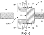
- FIG. 6 is a cross section in the region of the specimen mounting assembly 108 with a test sample 600 mounted or attached to the stationary specimen mount 132 and the movable specimen mount 134 using one or more fasteners 602 such as tape, epoxy, clamps, etc.
- the test sample 600 may be, for example, a rectangular strip of flexible material that is wrapped at least partially, or completely, around the circumference of both the stationary specimen mount 132 and the movable specimen mount 134. As depicted in FIG.
- the test sample 600 spans a recess 604 formed by one or both of the stationary specimen mount 132 and the movable specimen mount 134, such that a portion of the test sample 600 that spans the recess 604 is physically unsupported by stationary specimen mount 132 and the movable specimen mount 134.
- FIG. 6 depicts the specimen mounting assembly 108 prior to testing the test sample 600.
- the striker bar 104 is in the ready position, prior to striking the exposed face 404 of the movable specimen mount 134.
- the device 100 if FIG. 1 is first placed into the ready position.
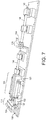
- the plate 122 is moved toward the electromagnet 124 by pressurizing the one or more gas pistons 128 using the gas source 130 to extend an arm 152 of each gas piston 128 such that the plate 122 engages or physically contacts the electromagnet 124 as depicted in FIG. 7 .
- the electromagnet 124 is powered to maintain the plate 122 in the ready position, and the gas pistons 128 are depressurized to retract the arms 152 away from the plate 122. In this position, a potential energy is imparted to the spring 118 within the channel assembly 123.
- FIG. 7 depicts the movable specimen mount 134 positioned away from the stationary specimen mount 132, with no test specimen positioned within the specimen mounting assembly 108.
- a test sample 600 will be positioned within the specimen mounting assembly 108 as depicted in FIG. 6 .
- a test may be initiated by removing power from the electromagnet 124.
- the potential energy imparted to the spring 118 is released and converted to kinetic energy, which propels the striker bar 104 toward the stretcher bar 106.
- a second end of the striker bar 104 may extend into the aperture 400 through the specimen mount support 136, and into the aperture 402 through the stationary specimen mount 132, to physically contact the exposed face 404 of the movable specimen mount 134.
- FIG. 8 depicts the striker bar 104 just as it makes contact with the face 404 of the movable specimen mount 134.
- the force the striker bar 104 places on the exposed face 404 of the movable specimen mount 134 may be increased, for example, by using a spring 118 with a higher compression force spring (i.e., a stiffer spring) and/or by moving the electromagnet 124 further away from the channel assembly 123 such that the spring 118 is placed under a higher potential energy in the ready position.
- the base 102 may include one or more slots 154 that receive one or more adjustment bolts 156 through an electromagnet mount 158. The adjustment bolts 156 may be loosened for repositioning of the electromagnet mount 158 and the electromagnet 124 attached to the electromagnet mount 158, and then tightened to secure the electromagnet mount 158 and the electromagnet 124.
- data may be collected by any number of desired data collection devices such as the high-speed camera 140 and/or the accelerometer 142.
- the striker bar 104 contacts the movable specimen mount 134, a pressure wave is generated that propagates through the movable specimen mount 134 and into the stretcher bar 106.
- the pressure wave reaches the second end of the stretcher bar 106 (i.e., the end opposite the movable specimen mount 134), it reflects off the second end and propagates back through the stretcher bar 106 and the movable specimen mount 134.
- the pressure wave continues to propagate back and forth multiple times through the bars and the test sample, thereby creating a non-continuous stress and non-continuous strain within and through the test sample.
- the striker bar 104 and the stretcher bar 106 of device 100 may be designed to provide a more continuous stress on the test sample 600.
- the striker bar 104 and the stretcher bar 106 of the device 100 may be designed or selected to trap the pressure wave within the striker bar 104 after only one cycle of the pressure wave through the stretcher bar 106.
- a first pressure wave is generated that propagates through the stretcher bar 106 to the second (opposite) end of the stretcher bar 106, and reflects off the second end back to the first end.
- a second pressure wave is generated that propagates through the striker bar 104 to the first (opposite) end of the striker bar 104, and reflects off the first end back to the second end.
- the striker bar 104 During the traversal of the first pressure wave through the stretcher bar 106, the striker bar 104 remains in physical contact with the exposed face 404. Once the first pressure wave returns to the first end of the stretcher bar 106, the first pressure wave enters the striker bar 104. At this point, the striker bar 104 and the stretcher bar 106 separate as depicted in FIG. 9 such that there is a gap 900 between the second end of the striker bar 104 and the exposed face 404 of the movable specimen mount 134 such that, when the first pressure wave reflects off the first end of the striker bar 104 and returns to the second end of the striker bar 104, the first pressure wave cannot reenter the stretcher bar 106.
- the second pressure wave cannot enter the stretcher bar 106.
- the gap 900 remains until after the test of the test sample 600 is completed.
- the test sample 600 is subjected to the pressure wave fewer times, thereby imparting a more continuous stress to the test sample during testing.
- the Split-Hopkinson pressure bar has a wave that continues to propagate and reflect through the test device and the test specimen. This creates a step motion and a non-constant strain. For at least this reason, a Split-Hopkinson pressure bar measurement is valid only during the first step.
- a compression wave is generated in both bars 104, 106.
- the compression waves propagate out from the impact location.
- the compression waves reflect as a tension wave moving back toward the interface between the two bars 104, 106 (i.e., toward the test sample 600).
- the net result is that the tension wave and oncoming compression wave combine to produce zero net stress.
- the tension wave from the striker bar 104 and the tension wave from the stretcher bar 106 meet, the tension waves combine to form a net tensile stress.
- the tensile stress first forms at the interface between the two bars 104, 106.
- the interface cannot support tension, so the bars 104, 106 separate.
- the stretcher bar 106 is then left with a stress wave that continues propagating and reflecting through the stretcher bar 106.
- This wave transit causes the stretcher bar 106 to have an undesirable step-motion and thus a non-constant strain in the test specimen 600.
- the stretcher bar 106 is shorter than the striker bar 104, the reflected tension waves meet and combine within the striker bar 104. When this tension wave reaches the interface between the two bars 104, 106, the tension wave causes separation of the two bars 104, 106 thereby trapping the waves within the striker bar 104, leaving the stretcher bar 106 with a smooth linear motion.
- the striker bar 104 and the stretcher bar 106 may be manufactured from the same material, for example, stainless steel, aluminum, other metals or metal alloys, or another suitable material.
- pressure waves travel through both the striker bar 104 and the stretcher bar 106 at the same rate.
- the timing of contact between the striker bar 104 and the stretcher bar 106 i.e., "contact timing" may be selected by providing a striker bar 104 having a first length and a stretcher bar 106 (including the movable specimen mount 134) having a second length, where the first length is longer than the second length.
- the first pressure wave traverses the stretcher bar 106 and enters the striker bar 104 before the second wave traverses the striker bar 104 because the second wave in the striker bar 104 has a longer distance to travel.
- striker bar 104 and stretcher bar 106 separate to form the gap 900.
- the striker bar 104 may be manufactured from a first material and the stretcher bar 106 may be manufactured from a second material, where the first material propagates a pressure wave at a slower rate or slower speed than the second material.
- the striker bar 104 and the stretcher bar 106 may have the same length and the contact timing is controlled by the materials from which the bars are formed.
- the striker bar 104 may be formed from brass while the stretcher bar 106 is formed from steel, where the wave speed in steel is approximately 1.7 times that of brass.
- the contact timing itself may thus be similar to that as described above, such that the first and second pressure waves are trapped within the striker bar 104 when the two bars 104, 106 separate and the gap 900 occurs.
- the materials selected such that the striker bar 104 and the stretcher bar 106 do not deform on impact, or so that any error in measurement of the sample 600 resulting from deformation is within acceptable tolerances.
- FIG. 10 is a flow chart depicting an exemplary method 1000 for testing or measuring a test sample according to an embodiment of the present teachings. It will be understood that the described method is an example method. When implemented, an method according to the present teachings may include fewer or additional processing stages than those described and/or depicted, and the described processing stages may be implemented in a different order than described herein. In addition, the method 1000 may proceed by operation of one or more portions of the apparatus of FIGS. 1-9 , 11, and 12 , and is thus described by reference thereto. However, it will be appreciated that the method 1000 is not limited to any particular structure unless otherwise expressly stated.
- test samples may be prepared for measurement as depicted at 1002.
- the test sample may be an elastic material, for example, a silicone or other polymer, or the test sample may be a solid such as a ceramic, a metal, a metal alloy, a natural or synthetic composite, etc.
- a sheet of test material may be prepared, for example, by dispensing a liquid or gel to a uniform or non-uniform thickness.
- the test material may be cured using thermal processing, ultraviolet light, or another suitable process.
- the test material may be formed, molded, cut, etc., into a desirable shape for testing.
- a sheet of test material may be sectioned into a plurality of test samples, such as a plurality of rectangular strips.
- a solid material may be, for example, pressed or stamped into a sheet, or drawn into a wire, for testing.
- a test sample may include a single layer of material, or two or more layers of one or more materials.
- the test sample may be prepared by forming one or more rectangular strips of a test material.
- FIG. 11 is an exploded magnified cross section of part of a specimen mounting assembly 108, and depicts a test sample 1100.
- the cross section of FIG. 11 is a section through a width of the test sample 1100, and the test sample 1100 may extend around a circumference of both the stationary specimen mount 132 and the movable specimen mount 134 partially or completely.
- the test sample 1100 may include a test material 1102 as well as a support material such as an epoxy, another synthetic or natural adhesive, or other support material adhered to two or more edges of the test material 1102 to provide attachment strips 1104.
- Tensile adhesion of the attachment strips 1104 to the test material 1102 should exceed the tensile stress at which the test material 1102 fails to prevent separation of the attachment strips 1104 from the test material 1102 during the test or measurement. Further, tensile strength of the attachment strips 1104 should exceed the tensile strength of the test material 1102 to prevent failure of the attachment strips 1104 prior to failure of the test material 1102.
- the attachment strips 1104 are sized and configured to fit within test sample grooves 1106 formed within and around the circumference of the stationary specimen mount 132 and the movable specimen mount 134. The stationary specimen mount 132 thereby receives a first portion of the test sample 1100 and maintains the first portion of the test sample in a fixed position during the test or measurement.
- preparation of the test sample 1100 may include coating the test material 1102 with a speckle pattern 1108 for use with, for example, digital image correlation.
- the speckle pattern 1108 may include, for example, a light-reflective polymer, a metal flake such as a silver flake, or another light-reflective material.
- the test sample is mounted to the specimen mounting assembly. This may include, for example, positioning the attachment strips 1104 within the test sample grooves 1106 as depicted in FIG. 12 .
- the test sample 1100 may be attached to the specimen mounting assembly 108 using one or more fasteners 1200, such as one or more adhesives, tape strips, epoxies, or other fastener 1200.
- the test material 1102 spans the recess 604 formed by one or both of the stationary specimen mount 132 and the movable specimen mount 134, such that at least a portion of the test material 1102 spans the recess 604 and is physically unsupported by stationary specimen mount 132 and the movable specimen mount 134.
- the specimen mounting assembly 108 depicted and described above is merely one design of mounting assembly, and others are contemplated.
- a method may include attaching the test sample to the specimen mounting assembly (or subassembly) at a location that is remote from the remainder of the device 100, and then the specimen mounting assembly may be subsequently attached to the remainder of the device 100 as depicted at 1006.
- the drive assembly 114 may be moved from a resting or idle position to a cocked or ready position as depicted at 1008.
- this may include filling the gas pistons 128 with gas from the gas source 130 to extend the arms 152, thereby moving the plate 122 into position against the electromagnet 124.
- the plate 122 is held against the electromagnet 124 using magnetism, which maintains the drive assembly 114, including the spring 118, in the ready position.
- the drive assembly 114 depicted and described above is merely one possible drive assembly, and other electrical, mechanical, electromechanical, pneumatic, and chemical drive assemblies are contemplated.
- the drive assembly 114 After placing the drive assembly 114 into the ready position, the drive assembly 114 is released or fired to initiate a test or measurement.
- power may be removed from the electromagnet 124, thereby releasing the plate 122 and the spring 118.
- the drive assembly 114 thereby propels the stretcher bar 106 toward the striker bar 104 using the force applied by the spring 118 as depicted at 1012.
- the striker bar 104 extends through the aperture 400 in the specimen mount support 136 and the aperture 402 in the stationary specimen mount 132 to impact the exposed face 404 of the movable specimen mount 134.
- the effects of the tensile stress may be measured as depicted at 1016 using, for example, a high-speed camera 140, an accelerometer 142, or another measurement technique.
- images from the high-speed camera 140 may capture the specimen 600, and particularly the speckle pattern 1108.
- Digital image correlation (DIC) may be used to calculate strain within the specimen 600.
- the high-speed video frames may be post processed using particle image velocimetry (PIV) techniques to allow tracking of, for example, the speckle pattern 1108 and calculation of strain of the sample 600.
- PAV particle image velocimetry
- an embodiment of the present teachings may include a device or apparatus for measuring dynamic stress/strain response of ductile materials, elastic materials, or other materials.
- a device in accordance with the present teachings may include only a striker and a stretcher bar.
- a pressure wave requires a longer time to travel through the striker bar than the stretcher bar, for example, by forming the striker bar to have a longer length than the stretcher bar or by forming the striker bar that propagates the pressure wave at a slower rate than the striker bar.
- the two bars stay in contact long enough for the pressure wave to reflect off the far end of the stretcher and run back into the striker.
- the bars separate leaving the stretcher bar with smooth forward motion until the specimen fails.
- Servo-hydraulic test frames work well at low strain rates but are unable to provide high stain rate loading.
- the device 100 may provide strain rate loading of above 2 strains per second, for example, in the range of about 100 to about 2500 strains per second. While the Split-Hopkinson pressure bar works well with brittle materials, it is not able to provide a constant strain rate over a large distance and, for at least this reason, is not appropriate for testing highly ductile materials to the point of failure.
- the numerical values as stated for the parameter can take on negative values.
- the example value of range stated as "less than 10" can assume negative values, e.g. - 1, -2, -3, -10, -20, -30, etc.
- one or more of the acts depicted herein may be carried out in one or more separate acts and/or phases.
- the terms “including,” “includes,” “having,” “has,” “with,” or variants thereof are used in either the detailed description and the claims, such terms are intended to be inclusive in a manner similar to the term “comprising.”
- the term “at least one of” is used to mean one or more of the listed items can be selected.
- the term “on” used with respect to two materials, one “on” the other means at least some contact between the materials, while “over” means the materials are in proximity, but possibly with one or more additional intervening materials such that contact is possible but not required.
- Terms of relative position as used in this application are defined based on a plane parallel to the conventional plane or working surface of a workpiece, regardless of the orientation of the workpiece.
- the term “horizontal” or “lateral” as used in this application is defined as a plane parallel to the conventional plane or working surface of a workpiece, regardless of the orientation of the workpiece.
- the term “vertical” refers to a direction perpendicular to the horizontal. Terms such as “on,” “side” (as in “sidewall”), “higher,” “lower,” “over,” “top,” and “under” are defined with respect to the conventional plane or working surface being on the top surface of the workpiece, regardless of the orientation of the workpiece.
Landscapes
- Physics & Mathematics (AREA)
- Health & Medical Sciences (AREA)
- Life Sciences & Earth Sciences (AREA)
- Chemical & Material Sciences (AREA)
- Analytical Chemistry (AREA)
- Biochemistry (AREA)
- General Health & Medical Sciences (AREA)
- General Physics & Mathematics (AREA)
- Immunology (AREA)
- Pathology (AREA)
- Investigating Strength Of Materials By Application Of Mechanical Stress (AREA)
Description
- The present teachings relate to the field of materials metrology and, more particularly, to a device for measuring stress and strain characteristics of a flexible pliable material or another material.
- This section provides background information related to the present disclosure which is not necessarily prior art.
- The design and manufacture of a structure requires the selection of appropriate materials for structural components or device substructures. To select a suitable material, scientists, engineers, designers, architects, etc., require specific knowledge of the material such as the stress and strain the material is able to withstand before failing. Most materials exhibit rate-dependent properties and many applications expose materials to both low and high strain rate loading.
- Various measurement devices have been developed for testing and quantifying the physical properties and stress characteristics of materials. For example, a Split-Hopkinson pressure bar may be used to test the dynamic stress-strain response of materials. During use of a Split-Hopkinson pressure bar, a specimen or test sample is placed between, and physically contacts, an incident bar and a transmission bar. At a first end of the incident bar away from the specimen, a stress wave, pressure wave, or incident wave is created using a striker bar. The incident wave propagates through the incident bar from the first end toward a second end that physically contacts the specimen. Upon reaching the specimen, a first portion of the energy from the incident wave travels through the specimen while a second portion is reflected away from the specimen and back through the incident bar. The first portion of the wave travels through, stresses, and deforms the specimen, and is then transferred to the transmission bar that physically contacts the specimen. Movement of the transmission bar may be stopped by a momentum bar and a momentum trap.
- When the first and second portions of the incident wave reach the ends of the incident bar and the transmission bar respectively, the portions of the incident wave reflect off the ends of the bars and rapidly travel back and forth through the bars multiple times. Each time the incident wave reaches the specimen end of the bars, a portion of the incident wave energy is transferred to the specimen, which is again subjected to increased stresses. These transits of the incident wave back and forth through the incident bar and the transmission bar, and thus through the specimen, create a stepping motion and a non-constant strain rate in the specimen. A Split-Hopkinson pressure bar measurement is therefore valid only during the first motion step, but many materials will not have failed during that first motion step.
- Additionally, the operational and failure characteristics of elastic materials such as vulcanizates (e.g., natural rubbers), elastomers (e.g., silicones, polymers), etc., are important considerations in selecting materials for use as sealers, barriers, vibration dampeners, shock absorbers and cushioners, as well as other uses. The Split-Hopkinson pressure bar subjects a test sample between the incident bar and the transmission bar to a compressive force as the incident wave travels through the test sample. The Split-Hopkinson pressure bar may thus test materials in tension, but does not function well for specimens that have a high strain to failure. Further, testing of a specimen using the Split-Hopkinson pressure bar subjects the material to a non-constant strain rate as the incident wave propagates back and forth through the incident bar and the transmission bar. The Split-Hopkinson pressure bar thus provides a high strain rate but not a high strain. Other devices using servo-mechanical methods may provide high strain but not a high strain rate.
- A device that is suitable for measuring various characteristics such as tensile strength and failure stresses at a constant strain rate of various materials such as flexible, pliable, and ductile materials, as well as other materials, that provides both a high strain rate and high strain, would be a welcome addition to the art.
- According to its abstract,
CN 203643279 describes a device for measuring the dynamic shearing property of a material, and which belongs to the technical field of testers. A test sample slot is formed in one end of a test sample fixing support; a screw hole is formed in each of two sides of the test sample slot; a shearing test sample is locked in the test sample slot through fixing screws; a cuboid punching head is arranged at one end of a shearing impact pressing head; therefore, the material dynamic shearing property measurement device is assembled and is arranged between an incidence rod and a transmission rod of a separate type Hopkinson pressing rod; the dynamic shearing property of the material can be directly measured by a conventional elastic wave excitation mode and a stress wave signal collection and processing method. - There is described herein an apparatus for measuring a dynamic tensile stress/strain response of a test sample. The apparatus comprises means for measuring an effect of the tensile stress on the test sample; a striker bar; a stretcher bar; a drive assembly configured to propel the striker bar toward the stretcher bar; a stationary specimen mount configured to receive a first portion of the test sample and to maintain the first portion of the test sample in a fixed position; and a movable specimen mount attached to a first end of the stretcher bar, the movable specimen mount configured to receive a second portion of the test sample. The striker bar is aligned with the stretcher bar and the striker bar is configured to impact with the movable specimen mount. The stretcher bar and the movable specimen mount are configured to move away from the stationary specimen mount from an impact of the striker bar with the movable specimen mount during a test or measurement of the test sample.
- There is also described herein a method for measuring a dynamic tensile stress/strain response of a test sample by employing the apparatus mentioned above. The method comprises: (a) propelling the striker bar toward the stretcher bar; (b) impacting the movable specimen mount with the striker bar; (c) moving the movable specimen mount away from the stationary specimen mount resulting from the striker bar impacting the movable specimen mount; (d) applying the dynamic tensile stress and/or strain to the test sample attached to the stationary specimen mount and to the movable specimen mount resulting from the moving of the movable specimen mount away from the stationary specimen mount; and (e) measuring the effect of the tensile stress on the test sample.
- The accompanying drawings, which are incorporated in and constitute a part of this specification, illustrate embodiments of the present teachings and together with the description, serve to explain the principles of the disclosure. In the figures:
-
FIG. 1 is a perspective depiction of a device according to an embodiment of the present teachings that may be used to measure and test characteristics and responses of a specimen. -
FIG. 2 is a plan view depicting theFIG. 1 structure. -
FIG. 3 is a side view depicting theFIG. 1 structure. -
FIG. 4 is a transparent side view depicting a specimen mounting assembly according to an embodiment of the present teachings. -
FIG. 5 is a perspective depiction including a specimen mounting assembly according to an embodiment of the present teachings. -
FIG. 6 is a side view depicting a specimen mounting assembly and a test sample according to an embodiment of the present teachings. -
FIG. 7 is a perspective depiction of theFIG. 1 device in a ready position. -
FIG. 8 is a side view of theFIG. 6 structure as the striker bar contacts the movable specimen mount. -
FIG. 9 is a side view of theFIG. 8 structure after impact of the movable specimen mount by the striker bar, and during exposure of the test sample to a tensile stress and/or stain. -
FIG. 10 is a flow chart of a method for testing or measuring a test sample according to an embodiment of the present teachings. -
FIG. 11 is a side view of a test sample, a stationary specimen mount, and a movable specimen mount according to an embodiment of the present teachings. -
FIG. 12 is a side view of theFIG. 11 structure after attaching the test sample. - It should be noted that some details of the FIGS. have been simplified and are drawn to facilitate understanding of the present teachings rather than to maintain strict structural accuracy, detail, and scale.
- Reference will now be made in detail to exemplary embodiments of the present teachings, examples of which are illustrated in the accompanying drawings. Wherever possible, the same reference numbers will be used throughout the drawings to refer to the same or like parts.
- The present teachings provide a method and structure for testing and/or obtaining performance data on a test specimen such as an elastic or non-elastic material sample. The method may include the dynamic measurement of tensile strength of the material sample over a relatively constant strain rate. While some conventional measurement techniques propagate a pressure wave back and forth multiple times through various device structures as well as the test specimen, which results in a non-constant stress/strain on the test specimen, a device or test structure of the present teachings may, in some embodiments, have a decreased pressure wave propagation through various device structures and the test sample, thereby resulting in more accurate stress and/or strain data.
-
FIG. 1 is a perspective depiction,FIG. 2 is a plan view, andFIG. 3 is a side view, of a device orapparatus 100 for testing and/or measuring tensile characteristics, performance data, or other physical properties of a test sample. It will be appreciated thatFIGS. 1-3 depict an exemplary structure, and that a measurement device in accordance with the present teachings may include other device substructures that are not depicted for simplicity, while various depicted device substructures may be removed or modified. - The
device 100 may include abase 102 to which other measurement device substructures are attached and/or mounted using one or more fasteners, for example, one or more screws, bolts, pegs, clips, clamps, adhesives, etc. (not individually depicted for simplicity). Themeasurement device 100 further includes astriker bar 104, astretcher bar 106, and aspecimen mounting assembly 108. - The
device 100 may further include one or more striker bar supports 110 attached to thebase 102 that guide and support thestriker bar 104, and allow axial movement of thestriker bar 104 toward and away from thestretcher bar 106 during use. Eachstriker bar support 110 may include one or more bearings 500 (FIG. 5 ), such as one or more bushings (for example, solid sleeve bushings or split bushings), roller bearings, or other low-friction supports, that support and allow low-friction axial movement of thestriker bar 104. Similarly, thedevice 100 may also include one or more stretcher bar supports 112 attached to thebase 102 that guide and support thestretcher bar 106 and allow axial movement of thestretcher bar 106 away from thestriker bar 104 during use. Eachstretcher bar support 112 may include one or more bearings, such as one or more bushings (for example, solid sleeve bushings or split bushings), roller bearings, or other low-friction supports, that support and allow low-friction axial movement of thestretcher bar 106. - The
device 100 ofFIGS. 1-3 further includes adrive assembly 114 and arelease assembly 116. Thedrive assembly 114 is configured to propel thestriker bar 104 toward thestretcher bar 106 using, for example, one or more springs, compressed gas, or another method. The force with which thedrive assembly 114 propels thestriker bar 104 may be adjustable, for example, to accommodate different test sample materials and test conditions. Therelease assembly 116 is configured to maintain or hold thestriker bar 104 in a ready, engaged, or cocked position and to release thestriker bar 104 to initiate a test or measurement (hereinafter, collectively, "test") of the test sample. In adrive assembly 114 including a spring, the spring may be held under tension when thedevice 100 is in the ready position. In adrive assembly 114 including a fast acting gas valve, the gas may be pressurized within a canister when thedevice 100 is in the ready position. In addition to those described herein, other implementations of thedrive assembly 114 and therelease assembly 116, as well as other assemblies of thedevice 100, are contemplated. - The
drive assembly 114 of thedevice 100 ofFIGS. 1-3 includes aspring 118 that encircles thestriker bar 104 and aretainer 120 attached to afirst end 119 of thespring 118. Asecond end 121 of thespring 118 may be secured to thestriker bar 104 within achannel assembly 123, where at least a portion of thespring 118 and a portion of thestriker bar 104 are positioned and/or enclosed within a channel of thechannel assembly 123. Thedrive assembly 114 may further include aplate 122 adjacent to theretainer 120. Theplate 122 may be manufactured to be or include a ferromagnetic material such as an iron, an iron alloy, or another ferromagnetic material. In an embodiment, theplate 122 may be attached to a first end of thestriker bar 104, and the first end of thestriker bar 104 may extend through a hole in theretainer 120. - The
release assembly 116 may include anelectromagnet 124 attached to apower source 126. Theelectromagnet 124 is positioned such that theplate 122 may be held in the ready position by theelectromagnet 124 after retracting theplate 122. - The
device 100 may further include one ormore retractors 128 to assist with retracting thedrive assembly 114 from an idle position to the ready position. Theretractors 128 retract theplate 122 away from thechannel assembly 123 to position theplate 122, thespring 118, and thestriker bar 104 into the ready position. Theretractors 128 may include one or more electric, gas, orhydraulic pistons 128 in fluid communication with a power, gas, or hydraulicfluid source 130. - The
specimen mounting assembly 108 includes astationary specimen mount 132 and amovable specimen mount 134, each of which receives the specimen (i.e., the test sample) during a test. Thestationary specimen mount 132 may be attached to aspecimen mount support 136, while themovable specimen mount 134 is attached to a first end of thestretcher bar 106. The specimen mounting assembly is described in more detail below with reference toFIGS. 4 and 5 . - One or more data collection devices may be used to collect data during testing. The data collection devices may include, for example, a high-
speed camera 140 focused, for example, on thespecimen mounting assembly 108 during testing. Data collection may also including anaccelerometer 142 positioned on a second end of thestretcher bar 106 or at another location suitable for monitoring a force and/or an acceleration of thestretcher bar 106 during testing. - The
device 100 is assembled such that thestriker bar 104 is targeted to be in axial alignment with thestretcher bar 106. In other words, an axis of thestriker bar 104 is aligned with an axis of thestretcher bar 106. To establish alignment ofdevice 100 substructures, any number ofspacers 150 may be positioned between the base 102 and one or more of thechannel assembly 123, the striker bar supports 110, thespecimen mount support 136, the stretcher bar supports 112, and/or at other locations as necessary or desired. - The base 102 may be a table or a surface secured to a table or other mounting surface. For most accurate test results, unintentional movement such as vibration of the
device 100 may be minimized during testing. This includes vibrations and other unintentional movement resulting from external sources such as other equipment. Components and subassemblies of thedevice 100 may be manufactured from various materials such as polymers, metals such as steel or aluminum, and/or other natural or synthetic materials. -
FIG. 4 is a plan view, andFIG. 5 is a perspective depiction, of thedevice 100 in the region of thespecimen mounting assembly 108.FIGS. 4 and 5 depict thedevice 100 in two different positions, but without a test sample affixed to thespecimen mounting assembly 108. As depicted, thespecimen mount support 136 includes anaperture 400 through which thestriker bar 104 extends during a test. Additionally, thestationary specimen mount 132 also includes anaperture 402 through which thestriker bar 104 extends during a test, where theaperture 400 is aligned with theaperture 402 to allow the passage of thestriker bar 104 therethrough. Theapertures striker bar 104 to extend or pass throughspecimen mount support 136 and thestationary specimen mount 132 to physically contact an exposedface 404 of themovable specimen mount 134, and to propel thestretcher bar 106 and the attachedmovable specimen mount 134 during testing.FIG. 5 also depictsbearings 500 in thestriker bar support 110 and thestretcher bar support 112 as described above. - As depicted, the stationary specimen mount may be removably or permanently mounted to the
specimen mount support 136 using afastener 406 such as one or more bolts or quick release fasteners. Themovable specimen mount 134 may be removably or permanently mounted to thestretcher bar 106 using afastener 408 such as one or more bolts or quick release fasteners. In another embodiment, thestationary specimen mount 132 and thespecimen mount support 136 may be fabricated from a single piece of material, such that thestationary specimen mount 132 is part of thespecimen mount support 136. Further, thestretcher bar 106 and themovable specimen mount 134 may be fabricated from a single piece of material, such that themovable specimen mount 134 is part of thestretcher bar 106. -
FIG. 6 is a cross section in the region of thespecimen mounting assembly 108 with atest sample 600 mounted or attached to thestationary specimen mount 132 and themovable specimen mount 134 using one ormore fasteners 602 such as tape, epoxy, clamps, etc. Thetest sample 600 may be, for example, a rectangular strip of flexible material that is wrapped at least partially, or completely, around the circumference of both thestationary specimen mount 132 and themovable specimen mount 134. As depicted inFIG. 6 , thetest sample 600 spans arecess 604 formed by one or both of thestationary specimen mount 132 and themovable specimen mount 134, such that a portion of thetest sample 600 that spans therecess 604 is physically unsupported bystationary specimen mount 132 and themovable specimen mount 134.FIG. 6 depicts thespecimen mounting assembly 108 prior to testing thetest sample 600. Thestriker bar 104 is in the ready position, prior to striking the exposedface 404 of themovable specimen mount 134. - To perform a test, the
device 100 ifFIG. 1 is first placed into the ready position. In the embodiment depicted, theplate 122 is moved toward theelectromagnet 124 by pressurizing the one ormore gas pistons 128 using thegas source 130 to extend anarm 152 of eachgas piston 128 such that theplate 122 engages or physically contacts theelectromagnet 124 as depicted inFIG. 7 . Theelectromagnet 124 is powered to maintain theplate 122 in the ready position, and thegas pistons 128 are depressurized to retract thearms 152 away from theplate 122. In this position, a potential energy is imparted to thespring 118 within thechannel assembly 123. - For purposes of illustration,
FIG. 7 depicts themovable specimen mount 134 positioned away from thestationary specimen mount 132, with no test specimen positioned within thespecimen mounting assembly 108. Typically, prior to positioning thedevice 100 in the ready position, atest sample 600 will be positioned within thespecimen mounting assembly 108 as depicted inFIG. 6 . - After placing the
test sample 600 into thespecimen mounting assembly 108 ofdevice 100 and positioning thedevice 100 into the ready position, a test may be initiated by removing power from theelectromagnet 124. The potential energy imparted to thespring 118 is released and converted to kinetic energy, which propels thestriker bar 104 toward thestretcher bar 106. During the testing phase, a second end of thestriker bar 104 may extend into theaperture 400 through thespecimen mount support 136, and into theaperture 402 through thestationary specimen mount 132, to physically contact the exposedface 404 of themovable specimen mount 134.FIG. 8 depicts thestriker bar 104 just as it makes contact with theface 404 of themovable specimen mount 134. - Subsequently, energy from the
striker bar 104 is transferred to themovable specimen mount 134 that is attached to thestretcher bar 106, and thestretcher bar 106 andmovable specimen mount 134 are propelled away from thestationary specimen mount 132, for example, as depicted inFIG. 9 . Movement of themovable specimen mount 134 away from thestationary specimen mount 132 thereby places a tensile stress and tensile strain on thetest sample 600 as depicted. If thestriker bar 104 is propelled with sufficient force, thetest sample 600 may partially or completely fail from the tensile stress or strain. - The force the
striker bar 104 places on the exposedface 404 of themovable specimen mount 134 may be increased, for example, by using aspring 118 with a higher compression force spring (i.e., a stiffer spring) and/or by moving theelectromagnet 124 further away from thechannel assembly 123 such that thespring 118 is placed under a higher potential energy in the ready position. In an embodiment, thebase 102 may include one ormore slots 154 that receive one ormore adjustment bolts 156 through anelectromagnet mount 158. Theadjustment bolts 156 may be loosened for repositioning of theelectromagnet mount 158 and theelectromagnet 124 attached to theelectromagnet mount 158, and then tightened to secure theelectromagnet mount 158 and theelectromagnet 124. - During testing of the test sample, data may be collected by any number of desired data collection devices such as the high-
speed camera 140 and/or theaccelerometer 142. - When the
striker bar 104 contacts themovable specimen mount 134, a pressure wave is generated that propagates through themovable specimen mount 134 and into thestretcher bar 106. When the pressure wave reaches the second end of the stretcher bar 106 (i.e., the end opposite the movable specimen mount 134), it reflects off the second end and propagates back through thestretcher bar 106 and themovable specimen mount 134. As described above, in the Split-Hopkinson pressure bar, the pressure wave continues to propagate back and forth multiple times through the bars and the test sample, thereby creating a non-continuous stress and non-continuous strain within and through the test sample. In contrast to the operation of the Split-Hopkinson pressure bar, thestriker bar 104 and thestretcher bar 106 ofdevice 100 may be designed to provide a more continuous stress on thetest sample 600. - In an embodiment, the
striker bar 104 and thestretcher bar 106 of thedevice 100 may be designed or selected to trap the pressure wave within thestriker bar 104 after only one cycle of the pressure wave through thestretcher bar 106. Upon initial contact between thestriker bar 104 and thestretcher bar 106 as depicted inFIG. 8 , a first pressure wave is generated that propagates through thestretcher bar 106 to the second (opposite) end of thestretcher bar 106, and reflects off the second end back to the first end. Similarly, upon this initial contact, a second pressure wave is generated that propagates through thestriker bar 104 to the first (opposite) end of thestriker bar 104, and reflects off the first end back to the second end. - During the traversal of the first pressure wave through the
stretcher bar 106, thestriker bar 104 remains in physical contact with the exposedface 404. Once the first pressure wave returns to the first end of thestretcher bar 106, the first pressure wave enters thestriker bar 104. At this point, thestriker bar 104 and thestretcher bar 106 separate as depicted inFIG. 9 such that there is a gap 900 between the second end of thestriker bar 104 and the exposedface 404 of themovable specimen mount 134 such that, when the first pressure wave reflects off the first end of thestriker bar 104 and returns to the second end of thestriker bar 104, the first pressure wave cannot reenter thestretcher bar 106. Similarly, the second pressure wave cannot enter thestretcher bar 106. The gap 900 remains until after the test of thetest sample 600 is completed. Thus, in contrast to the Split-Hopkinson pressure bar that subjects the test sample to the pressure wave multiple times, thetest sample 600 is subjected to the pressure wave fewer times, thereby imparting a more continuous stress to the test sample during testing. In contrast, the Split-Hopkinson pressure bar has a wave that continues to propagate and reflect through the test device and the test specimen. This creates a step motion and a non-constant strain. For at least this reason, a Split-Hopkinson pressure bar measurement is valid only during the first step. - In an embodiment, when the
striker bar 104 impacts the stretcher bar 106 a compression wave is generated in bothbars bar bars 104, 106 (i.e., toward the test sample 600). The net result is that the tension wave and oncoming compression wave combine to produce zero net stress. However, when the tension wave from thestriker bar 104 and the tension wave from thestretcher bar 106 meet, the tension waves combine to form a net tensile stress. If thestriker bar 104 and thestretcher bar 106 are of equal length, the tensile stress first forms at the interface between the twobars bars stretcher bar 106 is then left with a stress wave that continues propagating and reflecting through thestretcher bar 106. This wave transit causes thestretcher bar 106 to have an undesirable step-motion and thus a non-constant strain in thetest specimen 600. However, if thestretcher bar 106 is shorter than thestriker bar 104, the reflected tension waves meet and combine within thestriker bar 104. When this tension wave reaches the interface between the twobars bars striker bar 104, leaving thestretcher bar 106 with a smooth linear motion. - In an embodiment, the
striker bar 104 and thestretcher bar 106 may be manufactured from the same material, for example, stainless steel, aluminum, other metals or metal alloys, or another suitable material. In this embodiment, pressure waves travel through both thestriker bar 104 and thestretcher bar 106 at the same rate. The timing of contact between thestriker bar 104 and the stretcher bar 106 (i.e., "contact timing") may be selected by providing astriker bar 104 having a first length and a stretcher bar 106 (including the movable specimen mount 134) having a second length, where the first length is longer than the second length. In this embodiment, the first pressure wave traverses thestretcher bar 106 and enters thestriker bar 104 before the second wave traverses thestriker bar 104 because the second wave in thestriker bar 104 has a longer distance to travel. Before the second wave reaches the second end of thestriker bar 104,striker bar 104 and stretcher bar 106 separate to form the gap 900. - In another embodiment, the
striker bar 104 may be manufactured from a first material and thestretcher bar 106 may be manufactured from a second material, where the first material propagates a pressure wave at a slower rate or slower speed than the second material. Thus, in this embodiment, thestriker bar 104 and thestretcher bar 106 may have the same length and the contact timing is controlled by the materials from which the bars are formed. In this embodiment, thestriker bar 104 may be formed from brass while thestretcher bar 106 is formed from steel, where the wave speed in steel is approximately 1.7 times that of brass. The contact timing itself may thus be similar to that as described above, such that the first and second pressure waves are trapped within thestriker bar 104 when the twobars striker bar 104 and thestretcher bar 106 do not deform on impact, or so that any error in measurement of thesample 600 resulting from deformation is within acceptable tolerances. -
FIG. 10 is a flow chart depicting anexemplary method 1000 for testing or measuring a test sample according to an embodiment of the present teachings. It will be understood that the described method is an example method. When implemented, an method according to the present teachings may include fewer or additional processing stages than those described and/or depicted, and the described processing stages may be implemented in a different order than described herein. In addition, themethod 1000 may proceed by operation of one or more portions of the apparatus ofFIGS. 1-9 ,11, and 12 , and is thus described by reference thereto. However, it will be appreciated that themethod 1000 is not limited to any particular structure unless otherwise expressly stated. - In an embodiment, one or more test samples may be prepared for measurement as depicted at 1002. The test sample may be an elastic material, for example, a silicone or other polymer, or the test sample may be a solid such as a ceramic, a metal, a metal alloy, a natural or synthetic composite, etc. In an embodiment, a sheet of test material may be prepared, for example, by dispensing a liquid or gel to a uniform or non-uniform thickness. The test material may be cured using thermal processing, ultraviolet light, or another suitable process. The test material may be formed, molded, cut, etc., into a desirable shape for testing. For example, a sheet of test material may be sectioned into a plurality of test samples, such as a plurality of rectangular strips. In an embodiment, a solid material may be, for example, pressed or stamped into a sheet, or drawn into a wire, for testing. A test sample may include a single layer of material, or two or more layers of one or more materials.
- In an embodiment, the test sample may be prepared by forming one or more rectangular strips of a test material. For example,
FIG. 11 is an exploded magnified cross section of part of aspecimen mounting assembly 108, and depicts atest sample 1100. The cross section ofFIG. 11 is a section through a width of thetest sample 1100, and thetest sample 1100 may extend around a circumference of both thestationary specimen mount 132 and themovable specimen mount 134 partially or completely. Thetest sample 1100 may include atest material 1102 as well as a support material such as an epoxy, another synthetic or natural adhesive, or other support material adhered to two or more edges of thetest material 1102 to provide attachment strips 1104. Tensile adhesion of the attachment strips 1104 to thetest material 1102 should exceed the tensile stress at which thetest material 1102 fails to prevent separation of the attachment strips 1104 from thetest material 1102 during the test or measurement. Further, tensile strength of the attachment strips 1104 should exceed the tensile strength of thetest material 1102 to prevent failure of the attachment strips 1104 prior to failure of thetest material 1102. In an embodiment, the attachment strips 1104 are sized and configured to fit withintest sample grooves 1106 formed within and around the circumference of thestationary specimen mount 132 and themovable specimen mount 134. Thestationary specimen mount 132 thereby receives a first portion of thetest sample 1100 and maintains the first portion of the test sample in a fixed position during the test or measurement. Further, themovable specimen mount 134 thereby receives a second portion of thetest sample 1100 and moves away from thestationary specimen mount 132 during the test or measurement of thetest sample 1100. In an embodiment, preparation of thetest sample 1100 may include coating thetest material 1102 with aspeckle pattern 1108 for use with, for example, digital image correlation. Thespeckle pattern 1108 may include, for example, a light-reflective polymer, a metal flake such as a silver flake, or another light-reflective material. - As depicted at 1004, the test sample is mounted to the specimen mounting assembly. This may include, for example, positioning the attachment strips 1104 within the
test sample grooves 1106 as depicted inFIG. 12 . Thetest sample 1100 may be attached to thespecimen mounting assembly 108 using one ormore fasteners 1200, such as one or more adhesives, tape strips, epoxies, orother fastener 1200. As depicted inFIG. 12 , thetest material 1102 spans therecess 604 formed by one or both of thestationary specimen mount 132 and themovable specimen mount 134, such that at least a portion of thetest material 1102 spans therecess 604 and is physically unsupported bystationary specimen mount 132 and themovable specimen mount 134. Thespecimen mounting assembly 108 depicted and described above is merely one design of mounting assembly, and others are contemplated. - In an embodiment, a method may include attaching the test sample to the specimen mounting assembly (or subassembly) at a location that is remote from the remainder of the
device 100, and then the specimen mounting assembly may be subsequently attached to the remainder of thedevice 100 as depicted at 1006. - Next, the
drive assembly 114 may be moved from a resting or idle position to a cocked or ready position as depicted at 1008. In thedevice 100 ofFIG. 2 , this may include filling thegas pistons 128 with gas from thegas source 130 to extend thearms 152, thereby moving theplate 122 into position against theelectromagnet 124. When power from thepower source 126 is engaged, theplate 122 is held against theelectromagnet 124 using magnetism, which maintains thedrive assembly 114, including thespring 118, in the ready position. Thedrive assembly 114 depicted and described above is merely one possible drive assembly, and other electrical, mechanical, electromechanical, pneumatic, and chemical drive assemblies are contemplated. - After placing the
drive assembly 114 into the ready position, thedrive assembly 114 is released or fired to initiate a test or measurement. In the device ofFIG. 2 , for example, power may be removed from theelectromagnet 124, thereby releasing theplate 122 and thespring 118. Thedrive assembly 114 thereby propels thestretcher bar 106 toward thestriker bar 104 using the force applied by thespring 118 as depicted at 1012. Thestriker bar 104 extends through theaperture 400 in thespecimen mount support 136 and theaperture 402 in thestationary specimen mount 132 to impact the exposedface 404 of themovable specimen mount 134. This causes a physical separation of thestationary specimen mount 132 and themovable specimen mount 134, and places a tensile stress on the test sample using a movement of the specimen mounting assembly as depicted at 1014. During the tensile stress, the effects of the tensile stress may be measured as depicted at 1016 using, for example, a high-speed camera 140, anaccelerometer 142, or another measurement technique. In an embodiment, images from the high-speed camera 140 may capture thespecimen 600, and particularly thespeckle pattern 1108. Digital image correlation (DIC) may be used to calculate strain within thespecimen 600. For example, the high-speed video frames may be post processed using particle image velocimetry (PIV) techniques to allow tracking of, for example, thespeckle pattern 1108 and calculation of strain of thesample 600. - Thus an embodiment of the present teachings may include a device or apparatus for measuring dynamic stress/strain response of ductile materials, elastic materials, or other materials. When measuring dynamic strength, constant rate loading is an important factor in obtaining accurate test or measurement results. In contrast to conventional devices such as the Split-Hopkinson pressure bar which has a relatively short impactor bar, a transmitting bar, and a receiving bar, a device in accordance with the present teachings may include only a striker and a stretcher bar. In an embodiment, a pressure wave requires a longer time to travel through the striker bar than the stretcher bar, for example, by forming the striker bar to have a longer length than the stretcher bar or by forming the striker bar that propagates the pressure wave at a slower rate than the striker bar. As a result, after impact of the striker bar with the stretcher bar, the two bars stay in contact long enough for the pressure wave to reflect off the far end of the stretcher and run back into the striker. At this point, while the wave is in the striker bar, the bars separate leaving the stretcher bar with smooth forward motion until the specimen fails. Servo-hydraulic test frames work well at low strain rates but are unable to provide high stain rate loading. In an embodiment of the present teachings, the
device 100 may provide strain rate loading of above 2 strains per second, for example, in the range of about 100 to about 2500 strains per second. While the Split-Hopkinson pressure bar works well with brittle materials, it is not able to provide a constant strain rate over a large distance and, for at least this reason, is not appropriate for testing highly ductile materials to the point of failure. - Notwithstanding that the numerical ranges and parameters setting forth the broad scope of the present teachings are approximations, the numerical values set forth in the specific examples are reported as precisely as possible. Any numerical value, however, inherently contains certain errors necessarily resulting from the standard deviation found in their respective testing measurements. Moreover, all ranges disclosed herein are to be understood to encompass any and all sub-ranges subsumed therein. For example, a range of "less than 10" can include any and all sub-ranges between (and including) the minimum value of zero and the maximum value of 10, that is, any and all sub-ranges having a minimum value of equal to or greater than zero and a maximum value of equal to or less than 10, e.g., 1 to 5. In certain cases, the numerical values as stated for the parameter can take on negative values. In this case, the example value of range stated as "less than 10" can assume negative values, e.g. - 1, -2, -3, -10, -20, -30, etc.
- While the present teachings have been illustrated with respect to one or more implementations, alterations and/or modifications can be made to the illustrated examples without departing from the scope of the appended claims. For example, it will be appreciated that while the process is described as a series of acts or events, the present teachings are not limited by the ordering of such acts or events. Some acts may occur in different orders and/or concurrently with other acts or events apart from those described herein. Also, not all process stages may be required to implement a methodology in accordance with one or more aspects or embodiments of the present teachings. It will be appreciated that structural components and/or processing stages can be added or existing structural components and/or processing stages can be removed or modified. Further, one or more of the acts depicted herein may be carried out in one or more separate acts and/or phases. Furthermore, to the extent that the terms "including," "includes," "having," "has," "with," or variants thereof are used in either the detailed description and the claims, such terms are intended to be inclusive in a manner similar to the term "comprising." The term "at least one of" is used to mean one or more of the listed items can be selected. Further, in the discussion and claims herein, the term "on" used with respect to two materials, one "on" the other, means at least some contact between the materials, while "over" means the materials are in proximity, but possibly with one or more additional intervening materials such that contact is possible but not required. Neither "on" nor "over" implies any directionality as used herein. The term "conformal" describes a coating material in which angles of the underlying material are preserved by the conformal material. The term "about" indicates that the value listed may be somewhat altered, as long as the alteration does not result in nonconformance of the process or structure to the illustrated embodiment. Finally, "exemplary" indicates the description is used as an example, rather than implying that it is an ideal. Other embodiments of the present teachings will be apparent to those skilled in the art from consideration of the specification and practice of the disclosure herein. It is intended that the specification and examples be considered as exemplary only, with a true scope and spirit of the present teachings being indicated by the following claims.
- Terms of relative position as used in this application are defined based on a plane parallel to the conventional plane or working surface of a workpiece, regardless of the orientation of the workpiece. The term "horizontal" or "lateral" as used in this application is defined as a plane parallel to the conventional plane or working surface of a workpiece, regardless of the orientation of the workpiece. The term "vertical" refers to a direction perpendicular to the horizontal. Terms such as "on," "side" (as in "sidewall"), "higher," "lower," "over," "top," and "under" are defined with respect to the conventional plane or working surface being on the top surface of the workpiece, regardless of the orientation of the workpiece.
Claims (14)
- An apparatus for measuring a dynamic tensile stress/strain response of a test sample (600, 1100), comprising:means for measuring an effect of the tensile stress on the test sample (600, 1100);a striker bar (104);a stretcher bar (106);a drive assembly (114) configured to propel the striker bar (104) toward the stretcher bar (106);a stationary specimen mount (132) configured to receive a first portion of the test sample (600, 1100) and to maintain the first portion of the test sample (600, 1100) in a fixed position; anda movable specimen mount (134) attached to a first end of the stretcher bar (106), the movable specimen mount (134) configured to receive a second portion of the test sample (600, 1100);wherein the striker bar (104) is aligned with the stretcher bar (106) and the striker bar (104) is configured to impact with the movable specimen mount (134), and wherein the stretcher bar (106) and the movable specimen mount (134) are configured to move away from the stationary specimen mount (132) from an impact of the striker bar (104) with the movable specimen mount (134) during a test or measurement of the test sample (600, 1100).
- The apparatus of claim 1, wherein:the striker bar (104) is configured to generate a pressure wave through the stretcher bar (106) resulting from the impact of the striker bar (104) with the movable specimen mount (134);the striker bar (104) and the stretcher bar (106) are configured such that the pressure wave traverses from a first end of the stretcher bar (106) to a second end of the stretcher bar (106) and back to the first end of the stretcher bar (106);the striker bar (104) and the movable specimen mount (134) are configured such that the pressure wave traverses from the movable specimen mount (134) into the striker bar (104) during physical contact of the striker bar (104) with the movable specimen mount (134); andthe striker bar (104) and the movable specimen mount (134) are configured to physically separate from each other after the pressure wave traverses from the movable specimen mount (134), thereby trapping the pressure wave within the striker bar (104) during the test or measurement of the test sample (600, 1100).
- The apparatus of claim 1 or claim 2, wherein:the striker bar (104) is formed from a first material;the stretcher bar (106) is formed from the first material;the striker bar (104) has a first length;the stretcher bar (106) has a second length; andthe first length is longer than the second length.
- The apparatus of claim 1 or claim 2, wherein:the striker bar (104) is formed from a first material;the stretcher bar (106) is formed from a second material that is different from the first material; andthe first material and the second material are configured such that the pressure wave travels at a slower rate through the first material than through the second material.
- The apparatus of any of claims 1-4, further comprising a specimen mount support (136) that receives the stationary specimen mount (132).
- The apparatus of claim 5, wherein the specimen mount support (136) comprises a first aperture (400) therethrough and the stationary specimen mount (132) comprises a second aperture (402) therethrough, and the striker bar (104) is configured to extend through the first aperture (400) and the second aperture (402) prior to impacting the movable specimen mount (134).
- The apparatus of any of claims 1-6, wherein:the drive assembly (114) comprises a channel assembly (123) and a spring (118), the spring being positioned within the channel assembly; andthe spring is configured to propel the striker bar (104) toward the stretcher bar (106).
- The apparatus of any of claims 1-7, wherein:the stationary specimen mount (132) comprises a first groove (1106) therein configured to receive the first portion of the test sample (600, 1100);the movable specimen mount (134) comprises a second groove (1106) therein configured to receive the second portion of the test sample (600, 1100); andat least one of the stationary specimen mount (132) and the movable specimen mount (134) comprises a recess (604) therein configured such that the test sample (600, 1100) spans the recess (604) during the test or measurement of the test sample (600, 1100).
- The apparatus of any of claims 1-8, further comprising a release assembly (116) configured to maintain the striker bar (104) in a ready position and to release the striker bar (104) to initiate the test or measurement.
- The apparatus of claim 9, wherein:the release assembly (116) comprises an electromagnet (124) electrically coupled with a power source (126);the release assembly (116) is configured to maintain the striker bar (104) in the ready position when the electromagnet (124) is powered; andthe release assembly (116) is configured to initiate the test or measurement upon removing power from the electromagnet (124).
- A method for measuring a dynamic tensile stress/strain response of a test sample (600, 1100) by employing the apparatus of any of claims 1 - 10, comprising:propelling the striker bar (104) toward the stretcher bar (106);impacting the movable specimen mount (134) with the striker bar (104);moving the movable specimen mount (134) away from the stationary specimen mount (132) resulting from the striker bar (104) impacting the movable specimen mount (134) ;applying the dynamic tensile stress and/or strain to the test sample (600, 1100) attached to the stationary specimen mount (132) and to the movable specimen mount (134) resulting from the moving of the movable specimen mount (134) away from the stationary specimen mount (132); andmeasuring the effect of the tensile stress on the test sample (600, 1100).
- The method of claim 11, further comprising:generating a pressure wave within the stretcher bar (106) resulting from the striker bar (104) impacting the movable specimen mount (134), wherein the pressure wave traverses from a first end of the stretcher bar (106) to a second end of the stretcher bar (106), and back to the first end of the stretcher bar (106);during physical contact of the striker bar (104) with the movable specimen mount (134), transferring the pressure wave from the movable specimen mount (134) into the striker bar (104); andafter transferring the pressure wave from the movable specimen mount (134), physically separating the striker bar (104) from the movable specimen mount (134) to form a gap therebetween, thereby removing the pressure wave from the stretcher bar (106) and trapping the pressure wave within the striker bar (104).
- The method of claim 11 or claim 12, further comprising propelling the striker bar (104) toward the stretcher bar (106) using the drive assembly (114).
- The method of any of claims 11-13, further comprising extending the striker bar (104) into the aperture (402) through the stationary specimen mount (132) prior to the impacting of the movable specimen mount (134) with the striker bar (104).
Applications Claiming Priority (1)
| Application Number | Priority Date | Filing Date | Title |
|---|---|---|---|
| US15/211,891 US10215674B2 (en) | 2016-07-15 | 2016-07-15 | Device for measuring the dynamic stress/strain response of ductile materials |
Publications (2)
| Publication Number | Publication Date |
|---|---|
| EP3270137A1 EP3270137A1 (en) | 2018-01-17 |
| EP3270137B1 true EP3270137B1 (en) | 2020-04-01 |
Family
ID=59315501
Family Applications (1)
| Application Number | Title | Priority Date | Filing Date |
|---|---|---|---|
| EP17180769.6A Active EP3270137B1 (en) | 2016-07-15 | 2017-07-11 | Device for measuring the dynamic stress/strain response of ductile materials |
Country Status (8)
| Country | Link |
|---|---|
| US (1) | US10215674B2 (en) |
| EP (1) | EP3270137B1 (en) |
| JP (1) | JP7002867B2 (en) |
| KR (1) | KR102341759B1 (en) |
| CN (1) | CN107621418B (en) |
| AU (1) | AU2017203538B2 (en) |
| BR (1) | BR102017014735B1 (en) |
| CA (1) | CA2971307C (en) |
Cited By (1)
| Publication number | Priority date | Publication date | Assignee | Title |
|---|---|---|---|---|
| CN111638118A (en) * | 2020-07-09 | 2020-09-08 | 河海大学 | Device and method for testing internal crack propagation of concrete after quantitative strain impact |
Families Citing this family (28)
| Publication number | Priority date | Publication date | Assignee | Title |
|---|---|---|---|---|
| US10481057B1 (en) * | 2016-12-01 | 2019-11-19 | National Technology & Engineering Solutions Of Sandia, Llc | Mechanical testing equipment for material characterization |
| CN108548735B (en) * | 2018-05-23 | 2024-04-16 | 东北大学 | Hopkinson pressure bar bullet electromagnetic recovery device |
| CN109342564A (en) * | 2018-11-12 | 2019-02-15 | 北京工业大学 | A kind of experimental rig for the propagation characteristic in jointed rock mass of stress wave under researching high-temperature |
| CN109668801B (en) * | 2019-01-07 | 2023-12-22 | 中国人民解放军陆军工程大学 | High-low temperature synchronous coupling Hopkinson pressure bar test system based on numerical control drive |
| CN109708971A (en) * | 2019-01-16 | 2019-05-03 | 浙江大学 | A kind of pulling and pressing integrated experimental rig of Hopkinson |
| CN110057663B (en) * | 2019-02-28 | 2024-07-16 | 西南交通大学 | Electromagnetic Hopkinson torsion bar clamping and releasing device |
| CN110220775B (en) * | 2019-06-21 | 2020-03-27 | 西南交通大学 | Measuring device based on sample transmissivity under impact loading of light gas gun |
| CN111665152A (en) * | 2019-08-22 | 2020-09-15 | 西北工业大学 | Material dynamic compression circulating loading device and method thereof |
| CN110411869B (en) * | 2019-09-02 | 2024-04-30 | 哈尔滨市黎明锅炉容器封头有限公司 | Hydropneumatic medium strain rate tensile test device and method |
| CN113049358A (en) * | 2019-12-26 | 2021-06-29 | 有研工程技术研究院有限公司 | Characterization method for dynamic fracture performance of metal material |
| CN111307573A (en) * | 2020-04-12 | 2020-06-19 | 北京工业大学 | Test device for researching propagation characteristics of stress waves in one-dimensional rock rod based on magnetic suspension technology |
| TWI724897B (en) | 2020-05-14 | 2021-04-11 | 財團法人工業技術研究院 | Strain measurement method and strain measurement apparatus |
| CN111855343B (en) * | 2020-06-28 | 2023-01-17 | 东南大学 | Rock joint dynamic mechanical property and wave propagation rule indoor experimental device and method |
| CN111879603B (en) * | 2020-09-09 | 2021-10-26 | 中南大学 | Air cannon high-speed impact test tool for composite material plate and application method thereof |
| CN112198046B (en) * | 2020-09-28 | 2022-02-22 | 北京理工大学 | Automatic loading rod assembling device for SHPB (split Homey bar) test |
| CN112539992B (en) * | 2020-12-02 | 2021-10-29 | 山东科技大学 | Hopkinson pressure bar experiment multistage pulse loading device and experiment method thereof |
| CN112857965B (en) * | 2021-01-08 | 2022-02-22 | 北京理工大学 | High-temperature heating system for SHPB test |
| CN113008658B (en) * | 2021-02-02 | 2024-05-03 | 广州城建职业学院 | Two ripples decompose self-balancing strutting arrangement based on biax SHPB experiment |
| CN112964540B (en) * | 2021-02-10 | 2024-09-10 | 江西理工大学 | Rock dynamic performance testing device and method under high water pressure and high ground stress coupling |
| CN113551985A (en) * | 2021-07-22 | 2021-10-26 | 辽宁科技大学 | Three-dimensional high-speed photographic device based on Hopkinson pressure bar test system |
| CN113405928B (en) * | 2021-08-19 | 2021-11-09 | 煤炭科学研究总院 | Impact warhead and impact test equipment with same |
| CN113640118B (en) * | 2021-08-24 | 2024-02-20 | 哈尔滨工业大学 | Material in-situ dynamic tensile loading test device |
| CN114047060B (en) * | 2021-09-03 | 2023-11-03 | 北京理工大学 | Sample assembly for dynamic compression and stretching mechanical property test of explosive welding interface |
| IT202100030854A1 (en) * | 2022-02-04 | 2023-08-04 | Univ Politecnica Delle Marche | APPARATUS FOR PERFORMING DYNAMIC TESTS ON MATERIALS AT INTERMEDIATE DEFORMATION RATE |
| CN115184141B (en) * | 2022-06-27 | 2024-06-07 | 武汉理工大学 | DIC-based reinforcement compressive deformation measurement method |
| CN115308058A (en) * | 2022-10-11 | 2022-11-08 | 中国矿业大学(北京) | Underground engineering support system high strain rate dynamic test and evaluation system and method |
| CN116818567B (en) * | 2023-08-30 | 2023-11-14 | 北京建筑大学 | Dynamic impact damage mechanical property evaluation method for brittle solid material |
| KR102642062B1 (en) * | 2023-10-17 | 2024-03-04 | 국방과학연구소 | Apparatus for testing the crash characteristics of crashing bodies |
Family Cites Families (30)
| Publication number | Priority date | Publication date | Assignee | Title |
|---|---|---|---|---|
| JPH0725675Y2 (en) * | 1989-07-31 | 1995-06-07 | 株式会社島津製作所 | Tensile impact tester |
| US6109093A (en) | 1996-12-12 | 2000-08-29 | European Community | Split Hopkinson bar testing apparatus |
| EP0849583A1 (en) * | 1996-12-12 | 1998-06-24 | European Community | Split Hopkinson bar testing apparatus |
| US7024922B1 (en) | 1999-07-02 | 2006-04-11 | Sri Sports Limited | Viscoelastic characteristic value-measuring apparatus and method of measuring viscoelastic characteristic value |
| JP3485841B2 (en) * | 1999-07-02 | 2004-01-13 | 紀壽 中川 | Viscoelastic property value measuring device and viscoelastic property value measuring method |
| US6848321B2 (en) | 2001-10-17 | 2005-02-01 | The Boeing Company | Bond strength measurement system using shock loads |
| JP3938757B2 (en) | 2002-04-08 | 2007-06-27 | 新日本製鐵株式会社 | Method and apparatus for precise measurement of tensile or compressive stress during high-speed deformation |
| US7516680B2 (en) | 2003-07-30 | 2009-04-14 | The Boeing Company | Strain energy shuttle apparatus and method |
| US7392708B2 (en) | 2005-05-06 | 2008-07-01 | The Boeing Company | Apparatus and method of measuring shear strain of thick adhesive bondlines |
| US7159470B2 (en) | 2005-05-20 | 2007-01-09 | The Boeing Company | Systems and methods of measuring residual stress in metallic materials |
| US7591168B2 (en) | 2007-02-02 | 2009-09-22 | Sony Ericsson Mobile Communications Ab | Test equipment system and method for testing a component |
| JP4830913B2 (en) | 2007-03-05 | 2011-12-07 | 株式会社Ihi | Dynamic tensile test method and apparatus |
| US8250928B2 (en) | 2008-07-09 | 2012-08-28 | The Boeing Company | Measurement of strain in an adhesively bonded joint including magnetostrictive material |
| JP5161168B2 (en) * | 2009-08-05 | 2013-03-13 | 株式会社神戸製鋼所 | Impact test equipment |
| US8527218B2 (en) | 2009-11-18 | 2013-09-03 | The Boeing Company | Strength measurement for bond lines |
| US8645086B1 (en) | 2010-09-18 | 2014-02-04 | The Boeing Company | Stress function calibration method |
| CN102135480B (en) * | 2010-12-17 | 2013-06-12 | 北京理工大学 | System and method for performing impact loading on micro test piece and measuring dynamic mechanical property |
| KR20130034321A (en) * | 2011-09-28 | 2013-04-05 | 한국건설기술연구원 | Concrete tension test and method for split hopkinson tension bar |
| US9063032B2 (en) | 2012-04-06 | 2015-06-23 | The Boeing Company | Signal monitoring system for monitoring strain applied to a composite component |
| CN103091159B (en) * | 2013-02-05 | 2014-08-27 | 中国人民解放军陆军军官学院 | Novel split Hopkinson pull bar apparatus |
| CN103207122B (en) * | 2013-04-15 | 2015-08-05 | 北京理工大学 | There is the miniature dynamic tension and compression experiment system of prestrain |
| CN103353425B (en) * | 2013-06-17 | 2015-06-17 | 宁波大学 | Observation and test apparatus for cavity evolution in test pieces under tensile impact and test method |
| US9261444B1 (en) | 2013-07-30 | 2016-02-16 | The Boeing Company | Apparatus, system, and method for in situ strength testing of a bonded joint |
| CN203643279U (en) | 2013-12-09 | 2014-06-11 | 北京有色金属研究总院 | Device for measuring dynamic shearing property of material |
| US9863859B2 (en) * | 2014-04-23 | 2018-01-09 | Mississippi State University Research And Technology Corporation | Serpentine load monitoring apparatus |
| GB2534679B (en) * | 2014-12-22 | 2017-01-18 | Rolls Royce Plc | An output member |
| CN104677760B (en) * | 2015-01-30 | 2017-02-22 | 西北工业大学 | Implementation method for equivalently loading incident wave in double-shaft split Hopkinson pressure bar and pull rod experiments |
| CN104678853B (en) * | 2015-01-30 | 2017-09-26 | 西北工业大学 | The Hopkinson pressure bar experiment apparatus control system loaded based on electromagnetic force |
| CN105424470A (en) * | 2015-11-18 | 2016-03-23 | 太原理工大学 | Clamping device and experiment method for split Hopkinson torsion bar test piece |
| CN105571961B (en) * | 2015-12-18 | 2018-05-15 | 西北工业大学 | Induction Hopkinson strut and tie loading device and experimental method |
-
2016
- 2016-07-15 US US15/211,891 patent/US10215674B2/en active Active
-
2017
- 2017-05-26 AU AU2017203538A patent/AU2017203538B2/en active Active
- 2017-06-20 CA CA2971307A patent/CA2971307C/en active Active
- 2017-07-05 JP JP2017132122A patent/JP7002867B2/en active Active
- 2017-07-07 BR BR102017014735-5A patent/BR102017014735B1/en active IP Right Grant
- 2017-07-11 EP EP17180769.6A patent/EP3270137B1/en active Active
- 2017-07-14 KR KR1020170089754A patent/KR102341759B1/en active IP Right Grant
- 2017-07-14 CN CN201710578668.8A patent/CN107621418B/en active Active
Non-Patent Citations (1)
| Title |
|---|
| None * |
Cited By (2)
| Publication number | Priority date | Publication date | Assignee | Title |
|---|---|---|---|---|
| CN111638118A (en) * | 2020-07-09 | 2020-09-08 | 河海大学 | Device and method for testing internal crack propagation of concrete after quantitative strain impact |
| CN111638118B (en) * | 2020-07-09 | 2022-02-11 | 河海大学 | Device and method for testing internal crack propagation of concrete after quantitative strain impact |
Also Published As
| Publication number | Publication date |
|---|---|
| US10215674B2 (en) | 2019-02-26 |
| KR102341759B1 (en) | 2021-12-21 |
| CA2971307C (en) | 2021-07-13 |
| CN107621418B (en) | 2021-09-17 |
| AU2017203538A1 (en) | 2018-02-01 |
| CN107621418A (en) | 2018-01-23 |
| BR102017014735B1 (en) | 2023-01-10 |
| JP2018048998A (en) | 2018-03-29 |
| JP7002867B2 (en) | 2022-01-20 |
| EP3270137A1 (en) | 2018-01-17 |
| BR102017014735A2 (en) | 2018-03-20 |
| KR20180008344A (en) | 2018-01-24 |
| CA2971307A1 (en) | 2018-01-15 |
| US20180017475A1 (en) | 2018-01-18 |
| AU2017203538B2 (en) | 2021-09-16 |
Similar Documents
| Publication | Publication Date | Title |
|---|---|---|
| EP3270137B1 (en) | Device for measuring the dynamic stress/strain response of ductile materials | |
| JP6573828B2 (en) | A method for determining the non-propagation threshold of fatigue cracks at high frequencies. | |
| US7500378B2 (en) | Micro-impact testing apparatus | |
| CN102364325B (en) | Method for testing bending fatigue reliability of low dimensional conducting material | |
| CN202216931U (en) | Flexural fatigue reliability test system for low dimensional conductive material | |
| CN114061872B (en) | Three-dimensional high-precision calibration system and method | |
| CN108169029B (en) | Electromechanical thermal coupling stress corrosion in-situ fatigue performance test device | |
| JPS63250548A (en) | Method and instrument for measuring loss coefficient, dynamic modulus of elasticity, dynamic modulus of elasticity in shear and dynamic poisson's ratio of bar material of sheet material | |
| CN103684039B (en) | Magnetostrictive inertial impact driver | |
| CN210036474U (en) | Line ruler calibrating device based on grating length measurement | |
| JP2007003425A (en) | Linear servo motor type oscillator | |
| KR101766016B1 (en) | Flexural fatigue testing device for rotor magnetic poles of direct-driven permanent magnet wind power generator | |
| RU58708U1 (en) | MICROMECHANICAL TEST DEVICE | |
| CN107433258B (en) | Ironless linear motors resonance vibration excitor | |
| Kimberley et al. | A hybrid experimental/numerical investigation of the response of multilayered MEMS devices to dynamic loading | |
| CN110671968A (en) | Hand-held spacecraft fragment collision simulation launching device and method | |
| CN118329670B (en) | Hydraulic engineering construction quality check out test set | |
| CN114371070B (en) | Clamp for debonding experiment of microsphere with interface strength of fiber matrix and use method | |
| Friend et al. | A traveling-wave linear piezoelectric actuator with enclosed piezoelectric elements–the “Scream” actuator | |
| CN116399731A (en) | Bending fatigue test device and bending fatigue test system | |
| JP2000278972A (en) | Driving device | |
| Carrasco et al. | Piezoelectric Driven Carbon Fiber Cilia Based Linear Actuators | |
| CN114894358A (en) | Recoil indirect testing device and testing method | |
| Chetwynd et al. | Design of micro-hammers for ultrasonic source applications | |
| Rosatti | Fatigue performance of macro-fiber piezoelectric composite actuator with respect to variable beam geometry |
Legal Events
| Date | Code | Title | Description |
|---|---|---|---|
| PUAI | Public reference made under article 153(3) epc to a published international application that has entered the european phase |
Free format text: ORIGINAL CODE: 0009012 |
|
| STAA | Information on the status of an ep patent application or granted ep patent |
Free format text: STATUS: REQUEST FOR EXAMINATION WAS MADE |
|
| 17P | Request for examination filed |
Effective date: 20170711 |
|
| AK | Designated contracting states |
Kind code of ref document: A1 Designated state(s): AL AT BE BG CH CY CZ DE DK EE ES FI FR GB GR HR HU IE IS IT LI LT LU LV MC MK MT NL NO PL PT RO RS SE SI SK SM TR |
|
| AX | Request for extension of the european patent |
Extension state: BA ME |
|
| GRAP | Despatch of communication of intention to grant a patent |
Free format text: ORIGINAL CODE: EPIDOSNIGR1 |
|
| STAA | Information on the status of an ep patent application or granted ep patent |
Free format text: STATUS: GRANT OF PATENT IS INTENDED |
|
| INTG | Intention to grant announced |
Effective date: 20181206 |
|
| GRAJ | Information related to disapproval of communication of intention to grant by the applicant or resumption of examination proceedings by the epo deleted |
Free format text: ORIGINAL CODE: EPIDOSDIGR1 |
|
| STAA | Information on the status of an ep patent application or granted ep patent |
Free format text: STATUS: REQUEST FOR EXAMINATION WAS MADE |
|
| INTC | Intention to grant announced (deleted) | ||
| STAA | Information on the status of an ep patent application or granted ep patent |
Free format text: STATUS: EXAMINATION IS IN PROGRESS |
|
| 17Q | First examination report despatched |
Effective date: 20190612 |
|
| GRAP | Despatch of communication of intention to grant a patent |
Free format text: ORIGINAL CODE: EPIDOSNIGR1 |
|
| STAA | Information on the status of an ep patent application or granted ep patent |
Free format text: STATUS: GRANT OF PATENT IS INTENDED |
|
| INTG | Intention to grant announced |
Effective date: 20191016 |
|
| GRAS | Grant fee paid |
Free format text: ORIGINAL CODE: EPIDOSNIGR3 |
|
| GRAA | (expected) grant |
Free format text: ORIGINAL CODE: 0009210 |
|
| STAA | Information on the status of an ep patent application or granted ep patent |
Free format text: STATUS: THE PATENT HAS BEEN GRANTED |
|
| AK | Designated contracting states |
Kind code of ref document: B1 Designated state(s): AL AT BE BG CH CY CZ DE DK EE ES FI FR GB GR HR HU IE IS IT LI LT LU LV MC MK MT NL NO PL PT RO RS SE SI SK SM TR |
|
| REG | Reference to a national code |
Ref country code: GB Ref legal event code: FG4D |
|
| REG | Reference to a national code |
Ref country code: CH Ref legal event code: EP Ref country code: AT Ref legal event code: REF Ref document number: 1251994 Country of ref document: AT Kind code of ref document: T Effective date: 20200415 |
|
| REG | Reference to a national code |
Ref country code: DE Ref legal event code: R096 Ref document number: 602017013857 Country of ref document: DE |
|
| REG | Reference to a national code |
Ref country code: IE Ref legal event code: FG4D |
|
| PG25 | Lapsed in a contracting state [announced via postgrant information from national office to epo] |
Ref country code: BG Free format text: LAPSE BECAUSE OF FAILURE TO SUBMIT A TRANSLATION OF THE DESCRIPTION OR TO PAY THE FEE WITHIN THE PRESCRIBED TIME-LIMIT Effective date: 20200701 |
|
| REG | Reference to a national code |
Ref country code: NL Ref legal event code: MP Effective date: 20200401 |
|
| REG | Reference to a national code |
Ref country code: LT Ref legal event code: MG4D |
|
| PG25 | Lapsed in a contracting state [announced via postgrant information from national office to epo] |
Ref country code: PT Free format text: LAPSE BECAUSE OF FAILURE TO SUBMIT A TRANSLATION OF THE DESCRIPTION OR TO PAY THE FEE WITHIN THE PRESCRIBED TIME-LIMIT Effective date: 20200817 Ref country code: GR Free format text: LAPSE BECAUSE OF FAILURE TO SUBMIT A TRANSLATION OF THE DESCRIPTION OR TO PAY THE FEE WITHIN THE PRESCRIBED TIME-LIMIT Effective date: 20200702 Ref country code: FI Free format text: LAPSE BECAUSE OF FAILURE TO SUBMIT A TRANSLATION OF THE DESCRIPTION OR TO PAY THE FEE WITHIN THE PRESCRIBED TIME-LIMIT Effective date: 20200401 Ref country code: NO Free format text: LAPSE BECAUSE OF FAILURE TO SUBMIT A TRANSLATION OF THE DESCRIPTION OR TO PAY THE FEE WITHIN THE PRESCRIBED TIME-LIMIT Effective date: 20200701 Ref country code: SE Free format text: LAPSE BECAUSE OF FAILURE TO SUBMIT A TRANSLATION OF THE DESCRIPTION OR TO PAY THE FEE WITHIN THE PRESCRIBED TIME-LIMIT Effective date: 20200401 Ref country code: IS Free format text: LAPSE BECAUSE OF FAILURE TO SUBMIT A TRANSLATION OF THE DESCRIPTION OR TO PAY THE FEE WITHIN THE PRESCRIBED TIME-LIMIT Effective date: 20200801 Ref country code: CZ Free format text: LAPSE BECAUSE OF FAILURE TO SUBMIT A TRANSLATION OF THE DESCRIPTION OR TO PAY THE FEE WITHIN THE PRESCRIBED TIME-LIMIT Effective date: 20200401 Ref country code: NL Free format text: LAPSE BECAUSE OF FAILURE TO SUBMIT A TRANSLATION OF THE DESCRIPTION OR TO PAY THE FEE WITHIN THE PRESCRIBED TIME-LIMIT Effective date: 20200401 Ref country code: LT Free format text: LAPSE BECAUSE OF FAILURE TO SUBMIT A TRANSLATION OF THE DESCRIPTION OR TO PAY THE FEE WITHIN THE PRESCRIBED TIME-LIMIT Effective date: 20200401 |
|
| REG | Reference to a national code |
Ref country code: AT Ref legal event code: MK05 Ref document number: 1251994 Country of ref document: AT Kind code of ref document: T Effective date: 20200401 |
|
| PG25 | Lapsed in a contracting state [announced via postgrant information from national office to epo] |
Ref country code: HR Free format text: LAPSE BECAUSE OF FAILURE TO SUBMIT A TRANSLATION OF THE DESCRIPTION OR TO PAY THE FEE WITHIN THE PRESCRIBED TIME-LIMIT Effective date: 20200401 Ref country code: LV Free format text: LAPSE BECAUSE OF FAILURE TO SUBMIT A TRANSLATION OF THE DESCRIPTION OR TO PAY THE FEE WITHIN THE PRESCRIBED TIME-LIMIT Effective date: 20200401 Ref country code: RS Free format text: LAPSE BECAUSE OF FAILURE TO SUBMIT A TRANSLATION OF THE DESCRIPTION OR TO PAY THE FEE WITHIN THE PRESCRIBED TIME-LIMIT Effective date: 20200401 |
|
| PG25 | Lapsed in a contracting state [announced via postgrant information from national office to epo] |
Ref country code: AL Free format text: LAPSE BECAUSE OF FAILURE TO SUBMIT A TRANSLATION OF THE DESCRIPTION OR TO PAY THE FEE WITHIN THE PRESCRIBED TIME-LIMIT Effective date: 20200401 |
|
| REG | Reference to a national code |
Ref country code: DE Ref legal event code: R097 Ref document number: 602017013857 Country of ref document: DE |
|
| PG25 | Lapsed in a contracting state [announced via postgrant information from national office to epo] |
Ref country code: ES Free format text: LAPSE BECAUSE OF FAILURE TO SUBMIT A TRANSLATION OF THE DESCRIPTION OR TO PAY THE FEE WITHIN THE PRESCRIBED TIME-LIMIT Effective date: 20200401 Ref country code: AT Free format text: LAPSE BECAUSE OF FAILURE TO SUBMIT A TRANSLATION OF THE DESCRIPTION OR TO PAY THE FEE WITHIN THE PRESCRIBED TIME-LIMIT Effective date: 20200401 Ref country code: DK Free format text: LAPSE BECAUSE OF FAILURE TO SUBMIT A TRANSLATION OF THE DESCRIPTION OR TO PAY THE FEE WITHIN THE PRESCRIBED TIME-LIMIT Effective date: 20200401 Ref country code: IT Free format text: LAPSE BECAUSE OF FAILURE TO SUBMIT A TRANSLATION OF THE DESCRIPTION OR TO PAY THE FEE WITHIN THE PRESCRIBED TIME-LIMIT Effective date: 20200401 Ref country code: EE Free format text: LAPSE BECAUSE OF FAILURE TO SUBMIT A TRANSLATION OF THE DESCRIPTION OR TO PAY THE FEE WITHIN THE PRESCRIBED TIME-LIMIT Effective date: 20200401 Ref country code: SM Free format text: LAPSE BECAUSE OF FAILURE TO SUBMIT A TRANSLATION OF THE DESCRIPTION OR TO PAY THE FEE WITHIN THE PRESCRIBED TIME-LIMIT Effective date: 20200401 Ref country code: RO Free format text: LAPSE BECAUSE OF FAILURE TO SUBMIT A TRANSLATION OF THE DESCRIPTION OR TO PAY THE FEE WITHIN THE PRESCRIBED TIME-LIMIT Effective date: 20200401 |
|
| PLBE | No opposition filed within time limit |
Free format text: ORIGINAL CODE: 0009261 |
|
| STAA | Information on the status of an ep patent application or granted ep patent |
Free format text: STATUS: NO OPPOSITION FILED WITHIN TIME LIMIT |
|
| PG25 | Lapsed in a contracting state [announced via postgrant information from national office to epo] |
Ref country code: SK Free format text: LAPSE BECAUSE OF FAILURE TO SUBMIT A TRANSLATION OF THE DESCRIPTION OR TO PAY THE FEE WITHIN THE PRESCRIBED TIME-LIMIT Effective date: 20200401 Ref country code: MC Free format text: LAPSE BECAUSE OF FAILURE TO SUBMIT A TRANSLATION OF THE DESCRIPTION OR TO PAY THE FEE WITHIN THE PRESCRIBED TIME-LIMIT Effective date: 20200401 Ref country code: PL Free format text: LAPSE BECAUSE OF FAILURE TO SUBMIT A TRANSLATION OF THE DESCRIPTION OR TO PAY THE FEE WITHIN THE PRESCRIBED TIME-LIMIT Effective date: 20200401 |
|
| REG | Reference to a national code |
Ref country code: CH Ref legal event code: PL |
|
| 26N | No opposition filed |
Effective date: 20210112 |
|
| REG | Reference to a national code |
Ref country code: BE Ref legal event code: MM Effective date: 20200731 |
|
| PG25 | Lapsed in a contracting state [announced via postgrant information from national office to epo] |
Ref country code: LU Free format text: LAPSE BECAUSE OF NON-PAYMENT OF DUE FEES Effective date: 20200711 Ref country code: LI Free format text: LAPSE BECAUSE OF NON-PAYMENT OF DUE FEES Effective date: 20200731 Ref country code: CH Free format text: LAPSE BECAUSE OF NON-PAYMENT OF DUE FEES Effective date: 20200731 |
|
| PG25 | Lapsed in a contracting state [announced via postgrant information from national office to epo] |
Ref country code: SI Free format text: LAPSE BECAUSE OF FAILURE TO SUBMIT A TRANSLATION OF THE DESCRIPTION OR TO PAY THE FEE WITHIN THE PRESCRIBED TIME-LIMIT Effective date: 20200401 Ref country code: BE Free format text: LAPSE BECAUSE OF NON-PAYMENT OF DUE FEES Effective date: 20200731 |
|
| PG25 | Lapsed in a contracting state [announced via postgrant information from national office to epo] |
Ref country code: IE Free format text: LAPSE BECAUSE OF NON-PAYMENT OF DUE FEES Effective date: 20200711 |
|
| PG25 | Lapsed in a contracting state [announced via postgrant information from national office to epo] |
Ref country code: TR Free format text: LAPSE BECAUSE OF FAILURE TO SUBMIT A TRANSLATION OF THE DESCRIPTION OR TO PAY THE FEE WITHIN THE PRESCRIBED TIME-LIMIT Effective date: 20200401 Ref country code: MT Free format text: LAPSE BECAUSE OF FAILURE TO SUBMIT A TRANSLATION OF THE DESCRIPTION OR TO PAY THE FEE WITHIN THE PRESCRIBED TIME-LIMIT Effective date: 20200401 Ref country code: CY Free format text: LAPSE BECAUSE OF FAILURE TO SUBMIT A TRANSLATION OF THE DESCRIPTION OR TO PAY THE FEE WITHIN THE PRESCRIBED TIME-LIMIT Effective date: 20200401 |
|
| PG25 | Lapsed in a contracting state [announced via postgrant information from national office to epo] |
Ref country code: MK Free format text: LAPSE BECAUSE OF FAILURE TO SUBMIT A TRANSLATION OF THE DESCRIPTION OR TO PAY THE FEE WITHIN THE PRESCRIBED TIME-LIMIT Effective date: 20200401 |
|
| P01 | Opt-out of the competence of the unified patent court (upc) registered |
Effective date: 20230516 |
|
| PGFP | Annual fee paid to national office [announced via postgrant information from national office to epo] |
Ref country code: GB Payment date: 20230727 Year of fee payment: 7 |
|
| PGFP | Annual fee paid to national office [announced via postgrant information from national office to epo] |
Ref country code: FR Payment date: 20230725 Year of fee payment: 7 Ref country code: DE Payment date: 20230727 Year of fee payment: 7 |