EP3268137B1 - Système de tamisage, tamiseur tourbillonnaire et utilisation d'un système de tamisage ou d'un tamiseur tourbillonnaire - Google Patents
Système de tamisage, tamiseur tourbillonnaire et utilisation d'un système de tamisage ou d'un tamiseur tourbillonnaire Download PDFInfo
- Publication number
- EP3268137B1 EP3268137B1 EP16709397.0A EP16709397A EP3268137B1 EP 3268137 B1 EP3268137 B1 EP 3268137B1 EP 16709397 A EP16709397 A EP 16709397A EP 3268137 B1 EP3268137 B1 EP 3268137B1
- Authority
- EP
- European Patent Office
- Prior art keywords
- screen
- resonator
- portafilter
- sieve
- ultrasonic
- Prior art date
- Legal status (The legal status is an assumption and is not a legal conclusion. Google has not performed a legal analysis and makes no representation as to the accuracy of the status listed.)
- Active
Links
- 238000012216 screening Methods 0.000 title claims description 40
- 238000002604 ultrasonography Methods 0.000 claims description 59
- 239000000411 inducer Substances 0.000 claims 2
- 239000000463 material Substances 0.000 description 20
- 230000010355 oscillation Effects 0.000 description 13
- 238000007789 sealing Methods 0.000 description 8
- 238000005452 bending Methods 0.000 description 7
- 230000008901 benefit Effects 0.000 description 7
- 238000007873 sieving Methods 0.000 description 7
- 230000008719 thickening Effects 0.000 description 7
- 239000004744 fabric Substances 0.000 description 4
- 125000006850 spacer group Chemical group 0.000 description 4
- 238000003466 welding Methods 0.000 description 4
- 229910000669 Chrome steel Inorganic materials 0.000 description 3
- 238000004026 adhesive bonding Methods 0.000 description 3
- 239000012528 membrane Substances 0.000 description 3
- 230000002093 peripheral effect Effects 0.000 description 3
- 239000000853 adhesive Substances 0.000 description 2
- 230000001070 adhesive effect Effects 0.000 description 2
- 230000005540 biological transmission Effects 0.000 description 2
- 239000004020 conductor Substances 0.000 description 2
- 238000013461 design Methods 0.000 description 2
- 230000000694 effects Effects 0.000 description 2
- 230000003993 interaction Effects 0.000 description 2
- 239000000565 sealant Substances 0.000 description 2
- 230000004323 axial length Effects 0.000 description 1
- 238000010276 construction Methods 0.000 description 1
- 238000005265 energy consumption Methods 0.000 description 1
- 230000005284 excitation Effects 0.000 description 1
- 238000010438 heat treatment Methods 0.000 description 1
- 230000001771 impaired effect Effects 0.000 description 1
- 230000009349 indirect transmission Effects 0.000 description 1
- 230000000977 initiatory effect Effects 0.000 description 1
- 239000002184 metal Substances 0.000 description 1
- 238000000034 method Methods 0.000 description 1
- 230000008569 process Effects 0.000 description 1
- 238000005476 soldering Methods 0.000 description 1
- 238000012549 training Methods 0.000 description 1
- 238000012546 transfer Methods 0.000 description 1
- 230000009466 transformation Effects 0.000 description 1
Images


Classifications
-
- B—PERFORMING OPERATIONS; TRANSPORTING
- B07—SEPARATING SOLIDS FROM SOLIDS; SORTING
- B07B—SEPARATING SOLIDS FROM SOLIDS BY SIEVING, SCREENING, SIFTING OR BY USING GAS CURRENTS; SEPARATING BY OTHER DRY METHODS APPLICABLE TO BULK MATERIAL, e.g. LOOSE ARTICLES FIT TO BE HANDLED LIKE BULK MATERIAL
- B07B1/00—Sieving, screening, sifting, or sorting solid materials using networks, gratings, grids, or the like
- B07B1/18—Drum screens
-
- B—PERFORMING OPERATIONS; TRANSPORTING
- B07—SEPARATING SOLIDS FROM SOLIDS; SORTING
- B07B—SEPARATING SOLIDS FROM SOLIDS BY SIEVING, SCREENING, SIFTING OR BY USING GAS CURRENTS; SEPARATING BY OTHER DRY METHODS APPLICABLE TO BULK MATERIAL, e.g. LOOSE ARTICLES FIT TO BE HANDLED LIKE BULK MATERIAL
- B07B1/00—Sieving, screening, sifting, or sorting solid materials using networks, gratings, grids, or the like
- B07B1/28—Moving screens not otherwise provided for, e.g. swinging, reciprocating, rocking, tilting or wobbling screens
- B07B1/40—Resonant vibration screens
-
- B—PERFORMING OPERATIONS; TRANSPORTING
- B07—SEPARATING SOLIDS FROM SOLIDS; SORTING
- B07B—SEPARATING SOLIDS FROM SOLIDS BY SIEVING, SCREENING, SIFTING OR BY USING GAS CURRENTS; SEPARATING BY OTHER DRY METHODS APPLICABLE TO BULK MATERIAL, e.g. LOOSE ARTICLES FIT TO BE HANDLED LIKE BULK MATERIAL
- B07B1/00—Sieving, screening, sifting, or sorting solid materials using networks, gratings, grids, or the like
- B07B1/42—Drive mechanisms, regulating or controlling devices, or balancing devices, specially adapted for screens
-
- B—PERFORMING OPERATIONS; TRANSPORTING
- B07—SEPARATING SOLIDS FROM SOLIDS; SORTING
- B07B—SEPARATING SOLIDS FROM SOLIDS BY SIEVING, SCREENING, SIFTING OR BY USING GAS CURRENTS; SEPARATING BY OTHER DRY METHODS APPLICABLE TO BULK MATERIAL, e.g. LOOSE ARTICLES FIT TO BE HANDLED LIKE BULK MATERIAL
- B07B1/00—Sieving, screening, sifting, or sorting solid materials using networks, gratings, grids, or the like
- B07B1/46—Constructional details of screens in general; Cleaning or heating of screens
-
- B—PERFORMING OPERATIONS; TRANSPORTING
- B07—SEPARATING SOLIDS FROM SOLIDS; SORTING
- B07B—SEPARATING SOLIDS FROM SOLIDS BY SIEVING, SCREENING, SIFTING OR BY USING GAS CURRENTS; SEPARATING BY OTHER DRY METHODS APPLICABLE TO BULK MATERIAL, e.g. LOOSE ARTICLES FIT TO BE HANDLED LIKE BULK MATERIAL
- B07B2230/00—Specific aspects relating to the whole B07B subclass
- B07B2230/04—The screen or the screened materials being subjected to ultrasonic vibration
Definitions
- the present invention deals with sieve systems with essentially cylindrical jacket-shaped, in particular essentially circular cylindrical jacket-shaped sieve surfaces and resonators for introducing ultrasonic vibrations according to the preamble of independent claim 1 as well as with eddy current sieving machines and uses of sieve systems or eddy current sieve machines.
- Such screening systems with, for example, circular cylindrical screen surfaces can be used, for example, in known eddy current screening machines.
- screening material is introduced into a screening chamber, where it is stimulated to form a turbulence flow using a rotor that is arranged in an interior space enclosed by the screening surface.
- a rotor that is arranged in an interior space enclosed by the screening surface.
- fine material is conveyed through the sieve surface, while coarse material is conveyed to a coarse material outlet arranged at the end of the sieve surface.
- a sieve basket contains three sleeves, between which a plastic sieve mesh is stretched. The cuffs are braced together using struts.
- the sieve basket is directly connected to vibration generators via vibration transmitters, which are attached to one of the sleeves. The vibration generators vibrate at a frequency of 30 to 200 Hz or at ultrasonic frequencies.
- the vibration transmitters are attached to one of the sleeves, only an indirect transmission of the ultrasonic vibrations to the screen mesh takes place.
- the vibration transmitter In order to still achieve sufficient ultrasonic amplitudes in the sieve fabric, the vibration transmitter must already oscillate with a high ultrasonic amplitude, which leads to a large energy expenditure that is actually unnecessary for the purpose of sieving and therefore also to unnecessary heating.
- the German utility model DE 20 2012 011 921 U1 shows a sieve device whose sieve layer is compacted by a forming process.
- the sieve layer can be stimulated with an ultrasonic generator.
- One embodiment of the screening device contains a screening cylinder for use in a cyclone screening machine.
- the screen fabric of the screening device is glued to three sleeves, of which the two outer sleeves are pressed apart using a tensioning device with three threaded rods. The vibrations are transmitted to the screen mesh via a feed rod exclusively via the middle sleeve.
- the German utility model DE 20 2012 101 287 U1 discloses a cylindrical or truncated cone-shaped strainer basket.
- This sieve basket has a sieve mesh which consists of metal wires that are sintered together. With the help of vibration transmitters and connecting pieces, vibrations are transmitted to a central sleeve to which the screen surfaces are attached.
- Two vibration generators are preferably provided, one in the ultrasonic range and one in a low-frequency range.
- the WO 2009/071221 A1 discloses a sieve system according to the preamble of claim 1, with a tubular sieve. To increase efficiency, it is necessary to oscillate the sieve in such a way that the amplitude of the ultrasonic vibration has a component in both the radial and axial directions of the tubular sieve.
- two ultrasound converters and two supply sound conductors are provided, which are connected to a screen frame at contact points.
- the document JP 2011-254446 A discloses a screening device including a mesh disposed within an outer frame, a metallic membrane contacting the underside of the mesh, and an ultrasonic transducer installed on the underside of a central portion of the membrane.
- the membrane includes a central part, a peripheral edge and radial connecting parts that connect the central part to the peripheral edge.
- the ultrasonic transducer is installed on the middle part. The ultrasonic vibration generated by the ultrasonic transducer is transmitted from the center part to the peripheral edge and connecting parts, causing the net to vibrate to prevent the net from clogging.
- the state of the art allows the introduction of ultrasonic vibrations into cylindrical jacket-shaped sieve surfaces.
- the ultrasonic vibrations are always introduced into the portafilter, which supports the sieve surface.
- the primary ultrasound amplitudes must therefore be chosen so large that the losses can be compensated for. This leads to unnecessarily high energy consumption and unnecessarily high temperatures for the actual purpose of sieving.
- the sieve system should allow a particularly effective introduction of the ultrasonic vibrations into the sieve surface, with as little energy as possible being introduced.
- the sieve surface can be designed, for example, as a sieve mesh.
- the screen surface extends along a longitudinal direction between the portafilters.
- the portafilters are designed in this way and arranged relative to one another so that the sieve surface clamped between them has a substantially cylindrical jacket-shaped shape.
- a surface (in particular a sieve surface) with a cylindrical shell-shaped shape is understood to mean a surface that results as a totality of distances, all of which run parallel to the longitudinal direction mentioned.
- the two portafilters define two top surfaces of the cylinder.
- the longitudinal direction and thus also the distances mentioned run essentially perpendicular to these cover surfaces, so that a straight cylinder jacket results.
- crooked cylinder jackets in which the longitudinal direction and thus also the distances do not run essentially perpendicular to the cover surfaces, are also conceivable and are within the scope of the invention.
- both the first and the second portafilter are essentially circular and the sieve surface is essentially circular cylindrical.
- the sieve surface is designed to be circular. This means that the conveying of the material to be screened through the screen surface with the help of a rotor, as already described at the beginning, is particularly effective and uniform.
- the screen surface in the cross-sectional planes mentioned has other shapes and is, for example, polygonal, such as square or hexagonal.
- the resonator is preferably designed and arranged in such a way that it is subjected to ultrasonic vibrations at a predefined frequency can be (for example with the help of an ultrasonic inductor described below) to oscillate in resonance. Oscillation in resonance is understood to mean not only oscillation at the maximum of the resonance curve, but also in a specific frequency range around this maximum, for example in a frequency range of approximately 3 dB around the maximum.
- the resonator can be designed as a hollow profile and consist of materials known per se, such as chrome steel or plastic.
- the resonator can form the pressure rod, and can therefore itself brace the portafilters together in such a way that a compressive stress is created between the portafilters; In these embodiments, additional push rods are not necessarily required. In other embodiments, the resonator is not a pressure rod that braces the portafilters together in such a way that a compressive stress arises between the portafilters.
- the resonator is attached to the sieve surface and essentially extends from the first portafilter to the second portafilter.
- the resonator does not necessarily have to be held by the first and/or second portafilter.
- the resonator preferably extends along at least 60%, more preferably at least 80% and even more preferably at least 90% of the length of the sieve surface measured in the longitudinal direction of the sieve surface.
- the ultrasonic vibrations can be introduced directly from the resonator into the screen surface.
- the introduction does not only take place indirectly via a portafilter or another sieve frame. This means that no ultrasonic vibrations need to be introduced into the portafilter. Consequently, less ultrasonic energy has to be applied to reduce the ultrasonic vibrations into the sieve surface. Since, according to the invention, the resonator also extends essentially from the first portafilter to the second portafilter, the introduction of ultrasonic energy into the sieve surface is increased even further.
- the sieve surface can have a length in the range of 100 mm to 1000 mm and a diameter in the range of 100 mm to 500 mm.
- the resonator can be held (directly or indirectly) on the first portafilter and/or on the second portafilter. This means that no further components are required to hold the resonator (apart from any decoupling elements described below). It is particularly preferred if the resonator is held (directly or indirectly) on both the first portafilter and the second portafilter.
- the compressive stress required for clamping the screen surface between the two portafilters can then be built up not only by the pressure rod, but also by the resonator.
- the push rod can also be formed by the resonator, so that no further push rods are required apart from the resonator.
- the resonator can have one or more oscillation nodes. It preferably has a first oscillation node at which it is held (directly or indirectly) on the first portafilter, and/or a second oscillation node at which it is held (directly or indirectly) on the second portafilter. Holding the resonator at a vibration node has the advantage that essentially no ultrasonic vibrations are transmitted from the resonator to the respective portafilter. This essentially prevents the transfer of ultrasonic energy to components (namely the portafilter), which do not need to be stimulated for the actual sieving function. The introduction of sound is therefore even more efficient.
- the resonator is held at the first oscillation node via a first decoupling element on the first portafilter and/or is held at the second oscillation node via a second decoupling element on the second portafilter;
- the resonator is then held indirectly on the first and/or second portafilter.
- the oscillation nodes are preferably arranged in opposite end regions of the resonator. This allows a shorter axial length of the decoupling elements to be achieved.
- the resonator can be attached to the portafilter and can also transmit pressure forces
- at least one of the decoupling elements is connected to the respective portafilter via a clamping device, for example if the second decoupling element is connected to the second portafilter via a clamping device.
- the clamping device can be formed, for example, by a clamping element provided with an external thread, which is firmly connected to the second decoupling element, a hole formed in the second portafilter and two clamping nuts. Through the interaction of the external thread with the bore and the clamping nuts, the clamping element can be attached and clamped to the second portafilter.
- the hole mentioned can be formed, for example, in a collar-shaped section of the second portafilter, described below.
- the first decoupling element can also be connected to the first portafilter via a clamping device. However, if the second decoupling element is already connected to the second portafilter via a clamping device, the first decoupling element can also be firmly connected to the first portafilter, for example by welding or screwing.
- the decoupling elements mentioned also have the advantage that, during assembly, they protect a resonator that is already attached to the screen surface against twisting, which could impair or destroy the attachment. In this way, in many cases in these exemplary embodiments there is no need for anti-twist protection, which will be described below.
- the push rod can also be connected to one or both portafilters via a clamping device as described above, it being sufficient if it is only connected to the second portafilter via a clamping device, but is firmly connected to the first portafilter, for example by welding or screwing.
- At least one and preferably both portafilters can have a sleeve-shaped section to which the sieve surface is attached, as well as a collar-shaped section which protrudes radially outwards from the sleeve-shaped section, on which at least one of the push rods is attached.
- a sleeve-shaped section allows the screen surface to be attached without it having to be bent or bent. It is also advantageous if the sieve surface is attached to the outside of the sleeve-shaped section.
- the screen surface can be attached to the sleeve-shaped section, for example with the help of a clamping ring or a hose clamp, and thus tensioned in the axial direction.
- the screen surface can be glued to the carrier, in particular to the sleeve-shaped section.
- At least one recess can be provided in the sleeve-shaped section of the portafilter in the direction of the other portafilter, i.e. in the longitudinal direction.
- An end of the resonator and/or a decoupling element as described above can be placed in this recess be included. The recess therefore allows the resonator and/or the decoupling element to be brought as close as possible to the collar-shaped section.
- the collar-shaped section of the portafilter can ensure stable transmission of pressure forces to the push rod.
- the resonator can be subjected to ultrasonic vibrations using an ultrasonic inductor.
- the ultrasound inductor can, for example, have a circular or rectangular cross section. It can be guided through a through opening formed in the first portafilter, in particular in the collar-shaped section of the first portafilter, into an intermediate region formed between the first portafilter and the second portafilter.
- the ultrasonic inductor is preferably guided through the feedthrough opening without contact, so that no ultrasonic vibrations are transmitted to the portafilter. Guiding the ultrasonic inductor through such a feedthrough opening advantageously allows the ultrasonic inductor to be designed straight, whereby the ultrasonic vibrations can be better transmitted to the resonator.
- the ultrasound inductor it is of course also within the scope of the invention for the ultrasound inductor to be curved, for example.
- the ultrasound inductor can be held via a fastening tube, which can be connected directly or indirectly to the collar-shaped section.
- the ultrasound inductor can be connected to an ultrasound converter which applies vibrations to it, for example via a threaded connection.
- One or more sleeves can be arranged between the ultrasound inductor and the fastening tube. Such sleeves can prevent the material being screened from escaping.
- the fastening tube can be connected to the collar-shaped section via an intermediate piece.
- the intermediate piece can be attached to the collar-shaped section of the portafilter using one or more screws.
- the intermediate piece can have one or more radial extensions with openings through which screws can be screwed into the collar-shaped section.
- the fastening tube mentioned also has the advantage that, during assembly, it protects a resonator that is already attached to the screen surface against twisting, which could impair or destroy the fastening. In this way, in many cases in these exemplary embodiments there is no need for anti-twist protection, which will be described below.
- the resonator it is conceivable and within the scope of the invention for the resonator to extend, for example in the form of a helix, from the first portafilter to the second portafilter to the second portafilter. However, it is preferred if the resonator extends essentially in the longitudinal direction from the first portafilter to the second portafilter. This allows the required length of the resonator to be reduced. By extending the resonator essentially in the longitudinal direction, the resonator can be built and assembled more easily without curvature.
- the resonator is attached to the screen surface essentially along its entire length. This allows the ultrasonic vibrations to be introduced even better into the sieve surface.
- the resonator can be attached to the screen surface, for example by gluing or soldering.
- the resonator can have a rectangular cross section perpendicular to the longitudinal direction. However, it can be advantageous if the resonator has a contact surface connected to the screen surface, which is adapted to the contour of the screen surface and for example, is concave. This also increases the efficiency of ultrasound introduction.
- the resonator is particularly advantageous for the resonator to be arranged on an outside of the screen surface and attached to it there. This does not impede the movement of a rotor already mentioned above, which is arranged in a rotor enclosed by the screen surface.
- the sieve system contains several resonators. These multiple resonators are then preferably distributed around the circumference of the sieve surface. In particular, they can be evenly distributed around the circumference of the sieve surface. This allows ultrasonic vibrations to be introduced more evenly into the sieve surface.
- the sieve system contains several pressure rods. These several pressure rods are then preferably evenly distributed around the circumference of the screen surface. This allows the pressure forces to be distributed evenly between the two portafilters.
- the sieve system can also contain one or more ultrasonic converters for generating the ultrasonic vibrations, which can be fed to the ultrasonic inductor. It is also within the scope of the invention that the ultrasound inductor contains connecting means for connecting to one or more ultrasound converters, which do not necessarily have to be part of the sieve system.
- the connecting means can be designed, for example, as a screw connection.
- the sieve system in addition to the first and second portafilter described above, can have at least a third essentially annular portafilter, at least two essentially cylindrical jacket-shaped sieve surfaces and at least two resonators Initiation of ultrasonic vibrations included.
- a first of the sieve surfaces is clamped between the first portafilter and the second portafilter, and a second of the sieve surfaces is clamped between the second portafilter and the third portafilter.
- At least a first of the resonators is designed to introduce ultrasonic vibrations directly into the first sieve surface, and at least a second of the resonators is designed to introduce ultrasonic vibrations directly into the second sieve surface.
- the extended sieve system further contains a first ultrasonic inductor, by means of which the first resonator can be subjected to ultrasonic vibrations, and a second ultrasonic inductor, by means of which the second resonator can be subjected to ultrasonic vibrations.
- the first ultrasonic introducer is guided through a feed-through opening formed in the first portafilter
- the second ultrasonic introducer is guided through a first feed-through opening formed in the first portafilter and a second feed-through opening formed in the second portafilter.
- the passages mentioned can, for example, be formed in a collar-shaped section of the respective portafilter as described above.
- This embodiment of an extended sieve system has the advantage that the ultrasound inductors can be carried out at the same axial position (with respect to a longitudinal direction of the sieve system).
- the first and second ultrasound inductors are connected or connectable to one and the same ultrasound converter.
- the second ultrasound inductor and the second resonator are offset in the circumferential direction with respect to a central axis of the sieve system relative to the first ultrasonic inductor and the first resonator, in particular by an angle in the range from 90° to 270°, preferably from 120° to 240°, particularly preferably from 150° to 210°, most preferably at an angle of 180°.
- the ultrasound can be transmitted particularly advantageously to the second sieve surface, since the first ultrasound inductor and the second ultrasonic inductor then influence each other less.
- the central axes of the portafilter preferably match.
- the portafilters are also preferably arranged equidistantly.
- the first and second cylindrical sieve surfaces preferably have the same diameter.
- the sieve system contains more than three portafilters, more than two sieve surfaces and more than two resonators with associated ultrasonic inductors and, if necessary, ultrasonic converters.
- At least one resonator has at least a first rod-shaped section with a first end and a second end and has at least a second rod-shaped section with a first end and a second end. Only the first rod-shaped section, but not also the second rod-shaped section, is attached to the screen surface. However, it is also conceivable that the first rod-shaped section is attached to a first sieve surface and the second rod-shaped section is attached to a second sieve surface. The first ends of the The first rod-shaped portion and the second rod-shaped portion are connected to each other, and the second ends of the first rod-shaped portion and the second rod-shaped portion are connected to each other.
- a resonator with two rod-shaped sections, bending vibrations that are known per se can be introduced into the screen surface.
- the amplitude of these bending vibrations runs in a radial direction with respect to a central axis of the sieve system.
- components of other vibration modes such as longitudinal vibrations can also be present.
- Such a resonator also has the advantage that the ultrasound can be introduced into the first rod-shaped section not only at the first end, but also at the second end of the first rod-shaped section via the second rod-shaped section. In this way, a more uniform vibration is created in the first rod-shaped section over the length of the rod.
- the vibration amplitudes are particularly small at the ends of the first rod-shaped section.
- the resonator is attached more reliably to the screen surface, since an adhesive connection provided, for example, is less likely to come loose.
- such a resonator can be tuned particularly easily to the frequency that excites it, for example by tuning the length of a slot formed between the first rod-shaped section and the second rod-shaped section.
- the ultrasonic vibrations can be introduced directly from the resonator into the sieve surface.
- the introduction does not only take place indirectly via a portafilter or another sieve frame. This means that there are no ultrasonic vibrations in the screen frame be initiated. Consequently, less ultrasonic energy has to be applied to introduce the ultrasonic vibrations into the sieve surface.
- the resonator is preferably not part of a screen frame of the screen system, which tensions the screen surface. In this way, the resonator can be decoupled from the screen frame, especially from low-frequency vibrations that are introduced directly into the screen frame.
- the resonator or an ultrasound inductor which applies ultrasonic vibrations to the resonator is guided through a feedthrough opening formed in a screen frame, in particular a portafilter of the screen frame.
- the ultrasonic inductor is preferably guided through the feedthrough opening without contact, so that no ultrasonic vibrations are transmitted to the portafilter.
- resonator The design of the resonator described above is not limited to sieve systems with annular portafilters, pressure rods and cylindrical jacket-shaped sieve surfaces. Rather, according to the invention, such resonators can also be used, for example, in sieve systems with a flat sieve surface.
- the sieve system preferably contains at least one ultrasonic inductor, by means of which the first ends of the first rod-shaped section and the second rod-shaped section can be subjected to ultrasonic vibrations.
- the ultrasound inductor can, for example, have a circular or rectangular cross section. It can be connected to the resonator, for example by screwing or welding.
- the resonator can have a connecting section, which connects the ultrasound inductor to the first ends of the two rod-shaped sections. This connecting section can have a rectangular cross section.
- first ends of the first rod-shaped section and the second rod-shaped section are connected to one another via a first U-shaped section and the second ends of the first rod-shaped section and the second rod-shaped section are connected to one another via a second U-shaped section are connected, wherein the first U-shaped section, the second U-shaped section and a central axis of the sieve system extend in a common radial plane.
- the first U-shaped section and thus the first ends of the rod-shaped sections can be subjected to ultrasonic vibrations by means of an ultrasound inductor.
- the first U-shaped section transforms a longitudinal vibration of an ultrasound inductor into a bending vibration.
- This sieve system contains at least one sieve surface and at least one resonator attached to the sieve surface for introducing ultrasonic vibrations directly into the sieve surface.
- This sieve system also contains at least one ultrasonic inductor, by means of which the resonator can be subjected to ultrasonic vibrations. In particular, it can be a sieve system described above.
- the ultrasonic introducer is guided through a feedthrough opening formed in a portafilter of the sieve system and through an anti-twist opening formed in an anti-twist protection.
- the anti-twist opening is designed and arranged and coordinated with the ultrasound inductor in such a way that it only allows rotation of the ultrasound inductor about its longitudinal axis within a predetermined angular range. This has the advantageous effect that the attachment of a resonator to the screen surface is protected if the resonator, an ultrasonic inductor or a decoupling element is attached directly or indirectly to the portafilter by screwing.
- the predetermined angular range is preferably smaller than 45°, more preferably smaller than 20°, particularly preferably smaller than 10°.
- an angular range of 10° means that the anti-twist opening allows the ultrasonic inductor to be rotated around a medium angular position in both directions of rotation by a maximum of 5°.
- an angular range limited in this way by the anti-twist opening ensures sufficient protection of the attachment of the resonator to the screen surface.
- the anti-rotation protection contains a plate having the anti-rotation opening and at least one spacer element which holds the plate at a distance from the feed-through opening, in particular in a direction from the portafilter away and towards the sieve surface.
- a distance makes it possible for sealants to be inserted between the plate with the anti-twist opening formed therein and the portafilter, which can prevent the screening material from passing through the feedthrough opening.
- the ultrasound inductor has a non-circular cross-section, for example a rectangular cross-section, and the anti-rotation opening is designed as an elongated hole. In this way, in particular, the above-mentioned angular ranges can be realized.
- the ultrasound introducer can have both a first section with a circular cross section and a second section with a non-circular cross section, in particular a rectangular cross section.
- the first section can face an ultrasonic converter and be guided through a feedthrough opening of a portafilter, and the second section can be guided through the anti-rotation opening.
- the anti-twist opening is preferably opened on one side, specifically in the radial direction inwards with respect to a central axis of the sieve system.
- it can contain a section in the shape of a segment of a circle, which merges into a slot that widens inwards in the radial direction, at the end of which the anti-rotation opening is open.
- the anti-twist protection can be pushed inwards in the radial direction over the ultrasound inductor, which thereby partially penetrates into the circular section through the slot.
- the slot can expand inwards in the radial direction. This can help ensure that the ultrasound introducer can be rotated within a predetermined angular range.
- the decoupling elements and fastening tubes described above can be dispensed with in many cases.
- At least one and preferably both portafilters have a circumferentially extending groove into which an elastic sealing ring, in particular an elastic O-ring, is inserted, which extends outwards in the radial direction the groove protrudes.
- an elastic sealing ring in particular an elastic O-ring
- the screen surface can be tensioned in the radial direction. In this way, the screen surface can be stretched homogeneously not only in the axial direction, but also in the radial direction. This allows the ultrasound to be introduced more homogeneously into the sieve surface, which in turn enables higher throughputs.
- At least one and preferably both portafilters have a sleeve-shaped section, on the radial outside of which the groove is formed.
- the sealing ring can be held particularly securely on the portafilter.
- a collar-shaped section as described above can protrude radially outwards from the sleeve-shaped section.
- the groove can be arranged on an axial end of the sleeve-shaped section facing the other portafilter, and an axial end of the screen surface can be held by means of a hose clamp on an axial end of the sleeve-shaped section facing away from the other portafilter.
- a hose clamp With such a hose clamp, the sieve surface can be tensioned particularly well in the axial direction over the sealing ring, so that this in turn can ensure tension in the radial direction.
- the groove can pass through a first axial boundary surface on a side facing away from the other portafilter and on a side facing the other portafilter Side may be limited by a second axial boundary surface, the first boundary surface having a greater extent in the radial direction than the second boundary surface. This makes it easier to insert the sealing ring into the groove. If the sieve surface is tensioned in the axial direction away from the other portafilter using a hose clamp, the sealing ring is prevented from slipping out of the groove.
- a sleeve-shaped extension can preferably be provided, which extends from the sleeve-shaped section of the portafilter in the direction of the other portafilter.
- the sleeve-shaped extension can be made thinner in the radial direction than the sleeve-shaped section, but it can run flush with the sleeve-shaped section on a radial inside.
- a thickening can extend radially outwards from the end of the sleeve-shaped extension.
- the groove can then be formed by an end face of the sleeve-shaped section, by the sleeve-shaped extension and by the thickening.
- the thickening preferably has a radial extent that is smaller than a radial extent of the end face mentioned.
- the groove can, for example, be milled into the portafilter, in particular in its sleeve-shaped section.
- the sealing ring can be made of rubber, for example.
- a further aspect of the invention relates to a cyclone screening machine which contains at least one screening system according to the invention as described above.
- This eddy current screening machine can contain a rotor which is arranged in an interior space enclosed by the screening surface. With the help of such a rotor, screening material located in the interior can be stimulated to form a vortex flow, whereby fine material can be conveyed outwards through the sieve surface, while coarse material can be conveyed to a coarse material outlet arranged at the end of the sieve surface can.
- the screening system can, for example, be aligned within the eddy current screening machine so that its longitudinal direction extends in a horizontal or vertical direction.
- the eddy current screening machine can contain one or more ultrasonic converters for generating the ultrasonic vibrations, which can be fed to the ultrasonic inductor.
- the invention also relates to the use of a screening system according to the invention described above, or a cyclone screening machine according to the invention as described above for control screening, separating, loosening, recovering and fractionating screening material.
- FIG. 1 Sieve system 10 shown contains a first annular portafilter 11 and a second annular portafilter 12, which are constructed identically to one another. However, in other embodiments not shown here, it is also conceivable that the two portafilters 11, 12 are not constructed identically to one another.
- a circular cylindrical jacket-shaped sieve surface 13 extending in a longitudinal direction L can be clamped between the portafilters 11, 12; However, for better illustration, this sieve surface 13 is only in Figure 2 shown.
- Each of the two portafilters 11, 12 each has a sleeve-shaped section 16 and 17 as well as a collar-shaped section 18 and 19 which projects radially outwards from the sleeve-shaped section 16 and 17.
- a respective clamping ring 27, 28 is provided on both sieve supports 11, 12, of which only the clamping ring 28 arranged on the second portafilter 12 is visible here .
- the sleeve-shaped sections 16, 17 also have four recesses 29 and 30, which are evenly distributed in the circumferential direction and which extend in the direction of the other portafilter 11, 12, i.e. also in the longitudinal direction L.
- pressure rods 14 which are evenly distributed in the circumferential direction and extend along the longitudinal direction L from the first portafilter 11 to the second portafilter 12, are attached to the collar-shaped sections 18, 19.
- the pressure rods 14 are attached to the first portafilter 11 by welding or screwing and are connected to the second portafilter 12 via a clamping device as described above. In this way, the pressure rods 14 clamp the portafilters 11, 12 together in such a way that a compressive tension arises between the portafilters 11, 12.
- two diametrically opposed and thus evenly distributed hollow-profile resonators 15 with a rectangular cross-section extend from the first portafilter 11 to the second portafilter 12.
- the resonators 15 can be made of chrome steel or plastic, for example.
- the resonators 15 each have a first and a second oscillation node. At the first oscillation node, the resonators 15 are held on the first portafilter 11 via a respective first decoupling element 22, and at the second oscillation node they are held on the second portafilter 12 via a respective second decoupling element 23. The ends of the resonators 15 are received in the recesses 29, 30 of the sleeve-shaped sections 16, 17.
- the ultrasonic inductors 25 are guided through the through openings 24 without contact, so that there are no ultrasonic vibrations be transferred directly to the first portafilter 11. They extend parallel to the longitudinal direction L of the sieve system 10 and have a circular cross section.
- the sieve system 10 can also contain one or more ultrasonic converters, not shown here, for generating the ultrasonic vibrations, which can be fed to the ultrasonic inductors 25 and then to the resonators 15.
- the at least one ultrasound converter can be connected to the ultrasound inductors 25, for example via a screw connection.
- Figure 2 shows the complete sieve system 10 with sieve surface 13.
- the sieve surface 13 is designed as a sieve fabric and results as a total of sections, all of which run parallel to the longitudinal direction L.
- the sieve surface 13 can have a length in the longitudinal direction L in the range of 100 mm to 1000 mm and a diameter in the range of 100 mm to 500 mm. It is attached to the outside of the sleeve-shaped section 17 of the second portafilter 12, which cannot be seen here, using the clamping ring 28.
- the sieve surface 13 can also be glued to the outside of the sleeve-shaped section 17.
- other types of fastening of the screen surface 13, not shown here are also conceivable.
- the resonators 15 are attached along their entire length by gluing to the outside of the screen surface 13. With the help of the two resonators 15, ultrasonic vibrations can be introduced into the sieve surface 13. Due to the elongated design of the resonators 15, they allow the generation of ultrasonic vibrations, which essentially only have a component in the longitudinal direction L of the sieve system. The attachment of the resonators 15 along their entire length ensures a particularly effective introduction of sound into the sieve surface 13.
- the Figure 3a shows a detailed side view of the attachment of the pressure rods 14 and the resonators 15 to the first portafilter 11.
- the ultrasound inductor 25 is guided without contact through the feed-through opening 24 formed in the collar-shaped section 18.
- the ultrasound inductor 25 is connected to the resonator 15 in order to be able to transmit ultrasound vibrations to it.
- the resonator 15 is held on the collar-shaped section 18 via the first decoupling element 22.
- the first decoupling element 22 is firmly connected to the collar-shaped section 18, for example by a welded connection.
- Figure 4a essentially the same section is shown in a top view. Overall, this construction means that ultrasonic vibrations can only be transmitted to the resonator 15, but not also to the first portafilter 11. This means that no ultrasonic vibration of the first portafilter 11 that is unnecessary for the actual purpose of sieving is generated.
- the attachment to the second portafilter 12 is designed differently, as can be seen from the detailed views Figures 3b and 4b results.
- the second decoupling element 23 is not firmly connected to the collar-shaped section 19. Instead, there is a clamping device here.
- This contains a clamping element 31 provided with an external thread, which is firmly connected to the second decoupling element 23.
- a hole 20 is provided in the collar-shaped section 19 of the second portafilter 12.
- the clamping element 31 and thus also the resonator 15 can be fastened and clamped to the collar-shaped section 19 of the second portafilter 12.
- the push rod 14 can be fastened and clamped in a bore 21 via a clamping device, which is not shown in detail here.
- Figure 4b shows essentially the same section in a top view.
- the decoupling elements 22, 23 also protect the resonator 15, which is already attached to the screen surface 13, against twisting, which could impair or destroy the attachment.
- an in Figure 8 The anti-twist protection shown can be dispensed with.
- Sieve system 10 shown can be used in a cyclone sieving machine, for example for control sieving, separating, loosening, recovering or fractionating sieves.
- the eddy current screening machine can contain a rotor which is arranged in an interior space enclosed by the screening surface 13. With the help of such a rotor, screening material located in the interior can be stimulated to form a vortex flow, whereby fine material can be conveyed outwards through the sieve surface 13, while coarse material can be conveyed to a coarse material outlet arranged at the end of the sieve surface.
- the second sieve system 10′ also contains a first annular portafilter 11′ and a second annular portafilter 12′, which are constructed essentially mirroring one another.
- a circular cylindrical jacket-shaped screen surface 13' extending in a longitudinal direction L is clamped between the portafilters 11', 12'.
- the first portafilter 11 ' only has one in Figure 5b recognizable sleeve-shaped section 16 'and a collar-shaped section 18' projecting radially outwards from the sleeve-shaped section 16'.
- the second portafilter 12' has a sleeve-shaped section 17' and a collar-shaped section 19' which projects radially outwards from the sleeve-shaped section 17'.
- the sieve surface 13 ' is secured on the outside of the sleeve-shaped sections
- a respective clamping ring is provided on both sieve supports 11 ', 12'.
- the sleeve-shaped sections here do not contain any recesses that extend in the direction of the other portafilter.
- Three pressure rods 14' are attached to the collar-shaped sections 18', 19' and extend along the longitudinal direction L from the first portafilter 11' to the second portafilter 12', of which only two can be seen.
- the push rods 14' are attached to the portafilters 11', 12' using clamping nuts 40'.
- a resonator 15' which can be made of chrome steel or plastic, extends along the longitudinal direction L from the first portafilter 11' essentially to the second portafilter 12'.
- This resonator 15 ' has a first rod-shaped section 32 with a first end 33 and a second end 34 and a second rod-shaped section 35 with a first end 36 and a second end 37. Only the first rod-shaped section 32, but not also the second rod-shaped section 35, is attached to the outside of the sieve surface 13 'by gluing.
- the first ends 33, 36 of the first rod-shaped section 32 and the second rod-shaped section 35 are connected to one another via a first U-shaped section 38, and the second ends 34, 37 of the first rod-shaped section 32 and the second rod-shaped section 35 are connected via a second U-shaped section 39 connected to each other.
- a through opening 24' is formed, through which an ultrasonic inductor 25' with a circular cross section extends into an intermediate region 26' of the sieve system 10' formed between the first portafilter 11' and the second portafilter 12'.
- the ultrasound introducer 25' is held on the collar-shaped section 18' using a fastening tube 45'.
- the ultrasound introducer 25 ' is attached to an ultrasound converter, not shown, via an indicated thread.
- Sleeves 46' between the fastening tube 45' and the ultrasonic inductor 25' prevent the screening material from escaping.
- the fastening tube 45' is connected to the collar-shaped section 18' via an intermediate piece 47'.
- the intermediate piece 47 ' contains in Figure 6 unrecognizable radial extensions with openings through which screws can be screwed into the collar-shaped section 18 '. In this way, the ultrasound introducer 25' is slidably mounted in the axial direction within the fastening tube 45' and the sleeves 46'.
- the fastening tube 45' also protects the resonator 15', which is already fastened to the sieve surface 13', against twisting, which could impair or destroy the fastening. In this way, an in. can also be accessed in this exemplary embodiment Figure 8
- the anti-twist protection shown can be dispensed with.
- the first U-shaped section 38 and thus the first ends 33, 36 of the rod-shaped sections 32, 35 can be subjected to ultrasonic vibrations.
- the resonator 15' can primarily introduce bending vibrations into the sieve surface 13', namely in a radial direction with respect to the central axis M of the sieve system 10'.
- the transformation of a longitudinal vibration of an ultrasonic single conductor into a bending vibration is carried out by the first U-shaped section 38.
- the resonator 15 also has the advantage that the ultrasound can be introduced into the first rod-shaped section 32 not only at the first end 33, but also at the second end 34 of the first via the second rod-shaped section 35 and the second U-shaped section 39 rod-shaped section 32. In this way, a more uniform vibration occurs in the first rod-shaped section 32 over the rod length.
- the oscillation amplitudes are particularly small at the first end 33 and at the second end 34 of the first rod-shaped section 32. This means that the resonator 15' is attached more reliably to the screen surface 13' because the adhesive bond is less likely to come loose. In addition, the resonator 15 'can be tuned particularly easily to the frequency that excites it, for example by tuning the length of a slot 42 formed between the first rod-shaped section 32 and the second rod-shaped section 35.
- FIG. 7 shows a third sieve system 10′′ according to the invention, which is designed as an extended sieve system.
- This contains a first essentially annular portafilter 11", a second essentially annular portafilter 12" and a third essentially annular portafilter 51", the central axes M of which coincide and which are arranged equidistantly.
- the sieve system also contains two pressure rods 14'', only one of which can be seen here. These pressure rods 14" clamp the portafilters 11", 12", 51” together in such a way that a compressive tension is created between the portafilters 11", 12", 51".
- the 14" push rods can be removed from the first portafilter 11'' extend through the second portafilter 12'' to the third portafilter 51''.
- first pressure rods 14" only extend from the first portafilter 11" to the second portafilter 12" and that second pressure rods 14" only extend from the second portafilter 12" to the third portafilter 51".
- the push rods 14" can, for example, as in the Figures 1 to 6 shown be attached to the portafilters 11'', 12", 51".
- the sieve system 10" further contains a first essentially cylinder-jacket-shaped sieve surface 13", which is clamped between the first portafilter 11" and the second portafilter 12", as well as a second essentially cylinder-jacket-shaped sieve surface 52", which is between the second portafilter 12 '' and the third portafilter 51 '' is clamped.
- the sieve surfaces 13", 52" are clamped as in the previously described exemplary embodiments.
- the sieve system 10" contains a first resonator 15" for introducing ultrasonic vibrations directly into the first sieve surface 13" and a second resonator 53" for introducing ultrasonic vibrations directly into the second sieve surface 52".
- first resonator 15 can be subjected to ultrasonic vibrations
- second resonator 53'' can be subjected to ultrasonic vibrations.
- the first ultrasonic inductor 25" is guided through a through opening 24" formed in the first portafilter 11" into a first intermediate region 26" formed between the first portafilter 11" and the second portafilter 12".
- the second ultrasonic inductor 54" is through a first through-opening 55" formed in the first portafilter 11" and a second through-opening 56" formed in the second portafilter 12" into one between the second portafilter 12" and the The second intermediate region 66" formed by the third portafilter 51" is guided.
- the second ultrasonic inductor 54" and the second resonator 53" are in the circumferential direction with respect to the central axis M of the sieve system 10" relative to the first ultrasonic inductor 25" and the first resonator 15" by 180 ° offset, so they are diametrically opposite each other. In this way, the ultrasonic inductors 25'', 54" influence each other particularly little.
- the ultrasonic inductors 25'', 54" can, similarly to the Figures 1 to 6 shown, can be held on the portafilters 11", 12", 51" with the help of decoupling elements or fastening tubes (not shown here). Alternatively or additionally, anti-twist protection can also be provided, as shown in FIG Figure 8 shown and described below.
- the first ultrasound introducer 25" is connected to a first ultrasound converter 57" and the second ultrasound introducer 54" is connected to a second ultrasound converter 58".
- the first ultrasonic converter 57" and the second ultrasonic converter 58" are connected to one and the same generator 59".
- both ultrasonic inductors 25", 54" are connected to one and the same ultrasonic converter.
- This embodiment results in a particularly space-saving arrangement for the extended sieve system 10'', since, among other things, the ultrasound inductors 25'', 54" can be carried out at the same axial position (with respect to a longitudinal direction of the sieve system 10'').
- FIG 8 shows a photo of a detail of a fourth sieve system 10′′′ according to the invention.
- This is also a sieve system 10′′′ with two essentially ring-shaped portafilters (of which only a first portafilter 11′′′ can be seen here), a cylindrical jacket-shaped sieve surface 13′′′ and a resonator 15′′, which is similar to that in the Figures 5a to 6
- the resonator 15" shown is formed and is attached directly to the sieve surface 13".
- the sieve system 10" contains an ultrasonic inductor 25"', by means of which the resonator 15" can be subjected to ultrasonic vibrations.
- the ultrasonic inductor 25" has a rectangular cross section and is guided through a through opening 24′′′, which is formed in a collar-shaped section 18′′′ of the first portafilter 11′′′.
- the sieve system 10′′′ also contains an anti-twist protection 60′′.
- This has a plate 62′′′, which is held at a distance from the feed-through opening 24′′′ with the help of two spacer elements 63′′′, namely in the direction away from the first portafilter 11′′′ and towards Sieve surface 13".
- Radial extensions 65" are formed on the spacer elements 63", which are fastened to the collar-shaped section 18" of the first portafilter 11" with the help of screws 64".
- the plate 62" has an anti-twist opening 61" designed as an elongated hole , through which the ultrasound inductor 25′′′ is also guided.
- the anti-twist opening 61′′′ allows the ultrasonic inductor 25′′′ to be rotated about its longitudinal axis only within a predetermined angular range.
- the angular range can be 10°, so that the anti-twist opening 61′′′ allows the ultrasonic inductor 25′′′ to be rotated around a medium angular position in both directions of rotation by a maximum of 5°.
- Figure 9a to 9c is a slightly modified variant of the fifth exemplary embodiment Figure 8 shown sieve system shown.
- Figure 9a shows the sieve system 10 ⁇ without the anti-twist protection 60'''', which is in Figure 9b is shown in detail.
- This sieve system 10 ⁇ also contains two essentially ring-shaped portafilters (of which only a first portafilter 11 ⁇ can be seen here), a cylindrical jacket-shaped sieve surface 13 ⁇ and a resonator 15 ⁇ , which is designed similarly to the resonator 15" shown in Figures 5a to 6 and directly is attached to the sieve surface 13 ⁇ .
- the resonator 15 ⁇ can be subjected to ultrasonic vibrations.
- the ultrasonic inductor 25 ⁇ has a first section 69 ⁇ with a circular cross section, which faces an ultrasound converter, and a second section 70 ⁇ with a rectangular cross section, which faces the resonator 15 ⁇ .
- the first section 69 ⁇ is guided through a through opening 24 ⁇ , which is formed in a collar-shaped section 18 ⁇ of the first portafilter 11 ⁇ .
- a plate 62 ⁇ of the anti-twist protection 60 ⁇ which is in Figure 9b is shown in detail, has an anti-twist opening 61 ⁇ , through which the second section 70 ⁇ of the ultrasonic inductor 25 ⁇ is guided (see Figure 9c ).
- the anti-rotation opening 61 ⁇ is open on one side, namely in the radial direction inwards with respect to a central axis of the sieve system. More precisely, the anti-rotation opening 61 ⁇ contains a segment-shaped section 67 ⁇ , which is in a radially inwardly expanding slot 68 ⁇ , at the end of which the anti-rotation opening 61 ⁇ is open.
- the anti-twist protection 60 ⁇ can be pushed inwards in the radial direction over the ultrasonic inductor 25 ⁇ , which partially penetrates into the circular section 67 ⁇ through the slot 68 ⁇ , and then fixed with the help of screws 64 ⁇ .
- the screws 64 ⁇ are in Figure 9c designed as hexagon socket screws. In the final position achieved in this way, there is no contact between the ultrasound inductor 25 ⁇ and the plate 62 ⁇ .
- the anti-twist opening 61 ⁇ allows the ultrasonic inductor 25 ⁇ to be rotated about its longitudinal axis only within a predetermined angular range. This rotation is made possible, among other things, by the fact that the slot 68 ⁇ widens inwards in the radial direction.
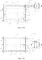
- FIGS. 10a to 10d show a sixth exemplary embodiment according to the invention of a sieve system 10 ⁇ with a first annular portafilter 11 ⁇ ′′′ and a second annular portafilter 12 ⁇ ′′′, which are constructed essentially mirrored to one another.
- Pressure rods 14 ⁇ ′′′ clamp the portafilters 11 ⁇ ′′′, 12 ⁇ ′′′ together in such a way that a compressive tension is created between the portafilters 11''''', 12 ⁇ ′′′.
- a circular cylinder jacket-shaped screen surface 13 ⁇ ′′′ extending in a longitudinal direction L is clamped with the help of two hose clamps 76 ⁇ ′′′.
- the first portafilter 11 ⁇ ′′′ has a sleeve-shaped section 16 ⁇ ′′′ and a collar-shaped section 18 ⁇ ′′′ which projects radially outwards from the sleeve-shaped section.
- the second portafilter 12 ⁇ ′′′ has a sleeve-shaped section (not visible here) and a collar-shaped section 19 ⁇ ′′′ protruding radially outwards from the sleeve-shaped section.
- a resonator 15 ⁇ ′′′ extends along the longitudinal direction L from the first portafilter 11 ⁇ ′′′ essentially to the second portafilter 12 ⁇ ′′′, which is identical to that in the Figures 5a to 6 is constructed as shown.
- the resonator 15 ⁇ ′′′ is excited to produce ultrasonic vibrations by means of an ultrasonic converter 77 ⁇ ′′′ and an ultrasonic inductor 25 ⁇ ′′′.
- the ultrasonic converter 77 ⁇ ′′′ is held on the collar-shaped section 18 ⁇ ′′′ of the first portafilter 11 ⁇ ′′′ with the help of a plate-shaped converter holder 79 ⁇ ′′′ and two spacers 78 ⁇ ′′′.
- the ultrasound inductor 25 ⁇ ′′′ is guided through a feed-through opening 24 ⁇ ′′′.
- Figures 8 to 9c Anti-twist protection shown can be provided.
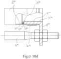
- FIG 10d is detail A Figure 10b shown enlarged.
- the sleeve-shaped section 16 ⁇ ′′′ of the first portafilter 11 ⁇ ′′′ has a groove 71 ⁇ ′′′ on its radial outside 73 ⁇ ′′′.
- a sealing ring designed as an O-ring 72 ⁇ ′′′ is inserted into this groove 71 ⁇ ′′′.
- the O-ring 72 ⁇ ′′′ protrudes slightly outwards in the radial direction beyond the groove 71 ⁇ ′′′ (which is not shown in the figures to simplify the drawing).
- the sieve surface 13 ⁇ ′′′ is tensioned in the radial direction.
- An axial end of the sieve surface 13 ⁇ ′′′ is held by means of a hose clamp 76 ⁇ ′′′ on an axial end 75 ⁇ ′′′ of the sleeve-shaped section 16 ⁇ ′′′ facing away from the second portafilter 12 ⁇ ′′′.
- FIG. 11a and 11b the first portafilter 11 ⁇ ′′′ is again shown separately and enlarged, whereby Figure 11b the detail X Figure 11a shows.
- a sleeve-shaped extension 80 ⁇ ′′′ extends from the sleeve-shaped section 16 ⁇ ′′′ in the direction of the second portafilter 12 ⁇ ′′′. It is thinner in the radial direction than the sleeve-shaped section 16 ⁇ ′′′, but runs flush with the sleeve-shaped section 16 ⁇ ′′′ on the radial inside 82 ⁇ ′′′. From the end of the sleeve-shaped extension 80 ⁇ ′′′, a thickening 81 ⁇ ′′′ extends radially outwards.
- the groove 71 ⁇ ′′′ is formed by an end face 83 ⁇ ′′′ of the sleeve-shaped section 16 ⁇ ′′′, by the sleeve-shaped extension 80 ⁇ ′′′ and by the thickening 81 ⁇ ′′′.
- the thickening 81 ⁇ ′′′ has a radial extent that is smaller than the radial extent of the end face 83 ⁇ ′′′. This makes it easier to insert the O-ring 72 ⁇ ′′′ into the groove 71 ⁇ ′′′. Since the sieve surface 13 ⁇ ′′′ is stretched in the axial direction away from the thickening 83 ⁇ ′′′ by means of the hose clamp 76 ⁇ ′′′, the O-ring 72 ⁇ ′′′ is prevented from slipping out of the groove 71 ⁇ ′′′.
Claims (15)
- Système de tamisage (10 ; 10' ; 10" ; 10‴ ; 10ʺʺ ; 10ʺ‴), comprenant- au moins un premier support de tamis essentiellement annulaire (11 ; 11' ; 11" ; 11‴ ; 11ʺʺ ; 11ʺ‴) et un deuxième support de tamis essentiellement annulaire (12 ; 12' ; 12" ; 12ʺ‴),- au moins une tige de compression (14 ; 14' ; 14" ; 14ʺ‴) qui serre les supports de tamis (11, 12 ; 11', 12' ; 11", 12", 51" ; 11‴ ; 11ʺʺ ; 11ʺ‴, 12ʺ‴) l'un contre l'autre de telle sorte qu'il se crée une tension de compression entre les supports de tamis (11, 12 ; 11', 12' ; 11", 12", 51" ; 11‴ ; 11ʺʺ ; 11ʺ‴, 12ʺ‴),- au moins une surface de tamisage (13 ; 13' ; 13", 52" ; 13‴ ; 13ʺʺ ; 13ʺ‴) essentiellement en forme d'enveloppe cylindrique, qui est serrée entre les supports de tamis (11, 12 ; 11', 12' ; 11", 12", 51" ; 11‴ ; 11ʺʺ ; 11ʺ‴, 12ʺ‴),- au moins un résonateur (15 ; 15' ; 15", 53" ; 15‴ ; 15ʺʺ ; 15ʺ‴) pour introduire des vibrations ultrasons directement dans la surface de tamisage (13 ; 13' ; 13", 52" ; 13‴ ; 13ʺʺ ; 13ʺ‴),le résonateur (15 ; 15' ; 15", 53" ; 15‴ ; 15ʺʺ ; 15ʺ‴) étant fixé à la surface de tamisage (13 ; 13' ; 13", 52" ; 13‴ ; 13ʺʺ ; 15ʺ‴),
caractérisé en ce que
le résonateur (15 ; 15' ; 15", 53" ; 15‴ ; 15ʺʺ ; 15ʺ‴) s'étend essentiellement du premier support de tamis (11 ; 11' ; 11" ; 11‴ ; 11ʺʺ ; 11ʺ‴) au deuxième support de tamis (12 ; 12' ; 12" ; 12ʺ‴). - Système de tamisage (10 ; 10' ; 10" ; 10‴ ; 10ʺʺ ; 10ʺ‴) selon la revendication 1,
caractérisé en ce que
le premier support de tamis (11 ; 11' ; 11" ; 11‴ ; 11ʺʺ ; 11ʺ‴) et le deuxième support de tamis (12 ; 12' ; 12" ; 12ʺ‴) sont réalisés essentiellement en forme d'anneau circulaire et la surface de tamisage (13 ; 13' ; 13", 52" ; 13‴ ; 13ʺʺ ; 13ʺ‴) est réalisée essentiellement en forme d'enveloppe de cylindre circulaire. - Système de tamisage (10) selon l'une des revendications précédentes,
caractérisé en ce que
le résonateur (15) est maintenu sur le premier support de tamis (11) et/ou sur le deuxième support de tamis (12). - Système de tamisage (10) selon la revendication 3,
caractérisé en ce que
le résonateur (15) présente un premier noeud d'oscillation par lequel il est maintenu sur le premier support de tamis (11) et/ou un deuxième noeud d'oscillation par lequel il est maintenu sur le deuxième support de tamis (12). - Système de tamisage (10) selon la revendication 4,
caractérisé en ce que
le résonateur (15) est maintenu au premier noeud d'oscillation par un premier élément de découplage (22) sur le premier support de tamis (11) et/ou est maintenu au deuxième noeud d'oscillation par un deuxième élément de découplage (23) sur le deuxième support de tamis (12). - Système de tamisage (10 ; 10' ; 10'' ; 10‴ ; 10ʺʺ ; 10ʺ‴) selon l'une des revendications précédentes,
caractérisé en ce que
au moins un support de tamis (11, 12 ; 11', 12' ; 11'', 12", 51" ; 11‴ ; 11ʺʺ ; 11ʺ‴, 12ʺ‴) présente une section en forme de manchon (16, 17 ; 16', 17' ; 16''''') à laquelle la surface de tamisage (13 ; 13' ; 13" , 52" ; 13ʺʺ ; 13'''''), ainsi qu'une section en forme de collerette (18, 19 ; 18'' ; 18ʺ‴) dépassant radialement vers l'extérieur de la section en forme de manchon (16, 17 ; 16', 17' ; 16'''''), à laquelle est fixée la au moins une tige de pression (14 ; 14' ; 14" ; 14ʺ‴). - Système de tamisage (10 ; 10' ; 10'' ; 10‴ ; 10ʺʺ ; 10''''') selon l'une des revendications précédentes,
caractérisé en ce que
il contient au moins un introducteur d'ultrasons (25 ; 25' ; 25", 54" ; 25‴ ; 25ʺʺ ; 25''''') au moyen duquel le résonateur (15 ; 15' ; 15'', 53'' ; 15''' ; 15ʺʺ ; 15''''') peut être soumis à des vibrations ultrasonores, l'introducteur d'ultrasons (25 ; 25' ; 25'', 53'' ; 25''' ; 25ʺʺ ; 25''''') étant traversé par une conduite d'air située dans le premier support de tamis (11 ; 11' ; 11'' ; 11‴ ; 11ʺʺ ; 11ʺ‴) est guidé dans une ouverture de passage (24 ; 24' ; 24'' ; 24‴ ; 24ʺʺ ; 24''''') formée entre le premier support de tamis (11 ; 11' ; 11'' ; 11‴ ; 11ʺʺ ; 11ʺ‴) et le deuxième support de tamis (12 ; 12' ; 12" ; 12''''') dans une zone intermédiaire (26 ; 26' ; 26" ; 26ʺ‴). - Système de tamisage (10 ; 10' ; 10'' ; 10‴ ; 10ʺʺ ; 10''''') selon l'une des revendications précédentes,
caractérisé en ce que
le résonateur (15 ; 15', 15'', 53'' ; 15''' ; 15ʺʺ ; 15''''') s'étend essentiellement dans la direction longitudinale (L) du premier support de tamis (11 ; 11' ; 11'' ; 11‴ ; 11ʺʺ ; 11ʺ‴) au deuxième support de tamis (12 ; 12' ; 12" ; 12ʺ‴). - Système de tamisage (10 ; 10''' ; 10'''' ; 10''''') selon l'une des revendications précédentes,
caractérisé en ce que
le résonateur (15 ; 15''' ; 15ʺʺ ; 15ʺ‴) est conçu pour introduire des vibrations ultrasonores qui ne présentent essentiellement qu'une composante dans la direction longitudinale (L). - Système de tamisage (10 ; 10' ; 10'' ; 10‴ ; 10ʺʺ ; 10''''') selon l'une des revendications précédentes,
caractérisé en ce que
le résonateur (15 ; 15' ; 15'', 53'' ; 15''' ; 15ʺʺ ; 15''''') est fixé à la surface de tamisage (13 ; 13' ; 13", 52" ; 13‴ ; 13ʺʺ ; 13ʺ‴) essentiellement sur toute sa longueur. - Système de tamisage (10 ; 10' ; 10'' ; 10‴ ; 10ʺʺ ; 10ʺ‴) selon l'une des revendications précédentes,
caractérisé en ce que
le résonateur (15 ; 15' ; 15'', 53'' ; 15''' ; 15ʺʺ ; 15ʺ‴) est collé ou brasé sur la surface de tamisage (13 ; 13' ; 13'', 52" ; 13‴ ; 13ʺʺ ; 13ʺ‴). - Système de tamisage (10 ; 10' ; 10'' ; 10‴ ; 10ʺʺ ; 10ʺ‴) selon l'une des revendications précédentes,
caractérisé en ce que
le résonateur (15 ; 15' ; 15'', 53'' ; 15''' ; 15ʺʺ ; 15ʺ‴) est disposé sur un côté extérieur de la surface de tamisage (13 ; 13' ; 13'', 52" ; 13‴ ; 13ʺʺ ; 13ʺ‴) et y est fixé. - Tamiseur centrifuge, contenant au moins un système de tamisage (10 ; 10' ; 10" ; 10‴ ; 10'''') selon l'une des revendications précédentes.
- Tamiseur centrifuge selon la revendication 13
caractérisé en ce que
le tamiseur centrifuge contient un ou plusieurs convertisseurs d'ultrasons pour générer les vibrations ultrasonores qui peuvent être amenées au résonateur (15 ; 15' ; 15'', 53" ; 15‴ ; 15ʺʺ). - Utilisation d'un système de tamisage (10 ; 10' ; 10'' ; 10‴ ; 10'''') selon l'une quelconque des revendications 1 à 12 ou d'un tamiseur centrifuge selon l'une des revendications 13 et 14 pour le tamisage de contrôle, la séparation, l'ameublissement, la récupération ou le fractionnement de matières à tamiser.
Applications Claiming Priority (4)
| Application Number | Priority Date | Filing Date | Title |
|---|---|---|---|
| PCT/EP2015/054936 WO2016141971A1 (fr) | 2015-03-10 | 2015-03-10 | Système de tamisage, tamiseur tourbillonnaire et utilisation d'un système de tamisage ou d'un tamiseur tourbillonnaire |
| PCT/EP2015/065093 WO2016142003A1 (fr) | 2015-03-10 | 2015-07-02 | Système de tamisage, tamiseur tourbillonnaire et utilisation d'un système de tamisage ou d'un tamiseur tourbillonnaire |
| EP15197213 | 2015-12-01 | ||
| PCT/EP2016/055099 WO2016142454A2 (fr) | 2015-03-10 | 2016-03-10 | Système de tamisage, tamiseur tourbillonnaire et utilisation d'un système de tamisage ou d'un tamiseur tourbillonnaire |
Publications (2)
| Publication Number | Publication Date |
|---|---|
| EP3268137A2 EP3268137A2 (fr) | 2018-01-17 |
| EP3268137B1 true EP3268137B1 (fr) | 2023-11-01 |
Family
ID=56878596
Family Applications (1)
| Application Number | Title | Priority Date | Filing Date |
|---|---|---|---|
| EP16709397.0A Active EP3268137B1 (fr) | 2015-03-10 | 2016-03-10 | Système de tamisage, tamiseur tourbillonnaire et utilisation d'un système de tamisage ou d'un tamiseur tourbillonnaire |
Country Status (4)
| Country | Link |
|---|---|
| US (1) | US10413942B2 (fr) |
| EP (1) | EP3268137B1 (fr) |
| JP (1) | JP6861163B2 (fr) |
| WO (1) | WO2016142454A2 (fr) |
Families Citing this family (2)
| Publication number | Priority date | Publication date | Assignee | Title |
|---|---|---|---|---|
| NL2014210B1 (nl) * | 2015-01-29 | 2017-01-27 | Oijense Bovendijk B V | Zeefinrichting en werkwijze voor het scheiden van droog korrelvormig materiaal. |
| CN108940812B (zh) * | 2018-09-10 | 2021-05-14 | 榫卯科技服务(温州)有限公司 | 一种化工原料筛选机 |
Family Cites Families (19)
| Publication number | Priority date | Publication date | Assignee | Title |
|---|---|---|---|---|
| US5213216A (en) * | 1989-12-28 | 1993-05-25 | Osaka Gas Company Limited | Vibratory sieve with screen and annular ring member thereon |
| CA2140755C (fr) * | 1993-05-26 | 2004-03-30 | Karl Frei | Procede et dispositif de filtrage, tamisage, triage ou separation |
| US5398816A (en) * | 1993-07-20 | 1995-03-21 | Sweco, Incorporated | Fine mesh screening |
| US5799799A (en) * | 1996-05-06 | 1998-09-01 | Kason Corporation | Ultrasonic screening system |
| JPH10244224A (ja) * | 1997-03-06 | 1998-09-14 | Taabo Kogyo Kk | 円筒スクリーン分級機 |
| DE19811266C1 (de) * | 1998-03-11 | 1999-08-05 | Hielscher Gmbh | Verfahren zum Anregen eines Siebrahmens mit Ultraschall |
| GB9822880D0 (en) * | 1998-10-21 | 1998-12-16 | Russel Finex | Improved efficiency ultrasonic sieving apparatus |
| US6845868B1 (en) * | 1999-03-28 | 2005-01-25 | Vibtec Engineering Ltd. | Multifrequency vibratory separator system, a vibratory separator including same, and a method of vibratory separation of solids |
| GB0122852D0 (en) * | 2001-09-21 | 2001-11-14 | Russel Finex | Seiving apparatus |
| US7182206B2 (en) * | 2002-05-03 | 2007-02-27 | M-I L.L.C. | Screen energizer |
| GB2395923A (en) * | 2002-12-02 | 2004-06-09 | Russel Finex | Sieving apparatus |
| US8564226B2 (en) * | 2006-08-10 | 2013-10-22 | Artech Systems Ag | Method and system for ultrasound excitation of structures with various arbitrary geometry |
| EP2067534A1 (fr) | 2007-12-05 | 2009-06-10 | Artech Systems AG | Système de criblage doté d'un crible tubulaire et procédé de fonctionnement d'un système de criblage doté d'un crible tubulaire |
| JP5419288B2 (ja) * | 2010-05-28 | 2014-02-19 | 株式会社東京製粉機製作所 | 篩装置 |
| US8973759B2 (en) * | 2011-03-17 | 2015-03-10 | Ricoh Company, Ltd. | Sieving device, sieving device for developing device, and powder-charging device |
| DE202012101287U1 (de) | 2012-04-11 | 2012-05-08 | Stefan Beidatsch | Siebsystem |
| DE102012104577A1 (de) | 2012-05-29 | 2013-12-05 | assonic Mechatronics GmbH | Zylindersieb für eine Siebmaschine |
| DE202012011921U1 (de) | 2012-12-13 | 2014-03-17 | Haver & Boecker Ohg | Siebeinrichtung |
| NL2014210B1 (nl) * | 2015-01-29 | 2017-01-27 | Oijense Bovendijk B V | Zeefinrichting en werkwijze voor het scheiden van droog korrelvormig materiaal. |
-
2016
- 2016-03-10 US US15/556,475 patent/US10413942B2/en active Active
- 2016-03-10 EP EP16709397.0A patent/EP3268137B1/fr active Active
- 2016-03-10 WO PCT/EP2016/055099 patent/WO2016142454A2/fr active Application Filing
- 2016-03-10 JP JP2017547483A patent/JP6861163B2/ja active Active
Also Published As
| Publication number | Publication date |
|---|---|
| EP3268137A2 (fr) | 2018-01-17 |
| WO2016142454A2 (fr) | 2016-09-15 |
| US10413942B2 (en) | 2019-09-17 |
| WO2016142454A3 (fr) | 2016-11-10 |
| US20180078971A1 (en) | 2018-03-22 |
| JP2018507780A (ja) | 2018-03-22 |
| JP6861163B2 (ja) | 2021-04-21 |
Similar Documents
| Publication | Publication Date | Title |
|---|---|---|
| DE102006047592B4 (de) | Vorrichtung zur Anregung eines in einem Siebrahmen eingefassten Siebgewebes mittels Ultraschall | |
| WO2009156207A1 (fr) | Unité émettrice d'ultrasons avec support | |
| EP2217388B1 (fr) | Système de criblage à tamis tubulaire et procédé d'exploitation d'un système de criblage à tamis tubulaire | |
| EP3268137B1 (fr) | Système de tamisage, tamiseur tourbillonnaire et utilisation d'un système de tamisage ou d'un tamiseur tourbillonnaire | |
| DE10108575A1 (de) | Ultraschallschwingungsvorrichtung zur Ultraschallbearbeitung | |
| DE19651643A1 (de) | Siebvorrichtung mit spaltförmigen Öffnungen | |
| WO2016141971A1 (fr) | Système de tamisage, tamiseur tourbillonnaire et utilisation d'un système de tamisage ou d'un tamiseur tourbillonnaire | |
| DE102012104577A1 (de) | Zylindersieb für eine Siebmaschine | |
| DE212017000184U1 (de) | Vorrichtung zum Ultraschallschweißen und Sonotrode für eine solche Vorrichtung | |
| DE102006037638A1 (de) | Verfahren und Vorrichtung zum Sieben, Klassieren, Filtern oder Sortieren trockener fester Stoffe oder fester Stoffe in Flüssigkeiten | |
| DE2522610C2 (de) | Verfahren und Vorrichtung zur lösbaren Verspannung von Mahlrohr und Tragsteg einer Rohrschwingmühle | |
| DE102015225428A1 (de) | Läufer für eine Strömungsmaschine | |
| EP3713682B1 (fr) | Unité de vibration ultrasonore avec amortissement | |
| EP3898010B1 (fr) | Système de soudage par ultrasons avec un dispositif de position angulaire | |
| EP3650211B1 (fr) | Dispositif d'agencement des barres de filtre à tamis | |
| EP0659516B2 (fr) | Appareil de soudage par ultrasons | |
| DE10015328B4 (de) | Fahrzeugkarosserie mit einer vorspannbaren Versteifungsvorrichtung | |
| AT524561B1 (de) | Siebvorrichtung zum Sieben von Schüttgut | |
| DE102006047591B4 (de) | Vorrichtung und Verfahren zum Sieben, Klassieren, Filtern oder Sortieren trockener fester Stoffe oder fester Stoffe in Flüssigkeiten | |
| DE102016117689B4 (de) | Sonotrodeneinheit sowie Verfahren zu ihrer Herstellung | |
| DE102007022653A1 (de) | Verfahren zum Bruchtrennen einer Pleuelstange | |
| DE102017106930B4 (de) | Siebeinrichtung | |
| EP3383546B1 (fr) | Boîtier pour électrofiltre humide et électrofiltre humide | |
| DE102015112734B3 (de) | Vorrichtung zum Spannen eines Werkstücks | |
| EP4260953A1 (fr) | Appareil de tamisage |
Legal Events
| Date | Code | Title | Description |
|---|---|---|---|
| STAA | Information on the status of an ep patent application or granted ep patent |
Free format text: STATUS: THE INTERNATIONAL PUBLICATION HAS BEEN MADE |
|
| PUAI | Public reference made under article 153(3) epc to a published international application that has entered the european phase |
Free format text: ORIGINAL CODE: 0009012 |
|
| STAA | Information on the status of an ep patent application or granted ep patent |
Free format text: STATUS: REQUEST FOR EXAMINATION WAS MADE |
|
| 17P | Request for examination filed |
Effective date: 20170907 |
|
| AK | Designated contracting states |
Kind code of ref document: A2 Designated state(s): AL AT BE BG CH CY CZ DE DK EE ES FI FR GB GR HR HU IE IS IT LI LT LU LV MC MK MT NL NO PL PT RO RS SE SI SK SM TR |
|
| AX | Request for extension of the european patent |
Extension state: BA ME |
|
| DAV | Request for validation of the european patent (deleted) | ||
| DAX | Request for extension of the european patent (deleted) | ||
| STAA | Information on the status of an ep patent application or granted ep patent |
Free format text: STATUS: EXAMINATION IS IN PROGRESS |
|
| STAA | Information on the status of an ep patent application or granted ep patent |
Free format text: STATUS: EXAMINATION IS IN PROGRESS |
|
| 17Q | First examination report despatched |
Effective date: 20211103 |
|
| GRAP | Despatch of communication of intention to grant a patent |
Free format text: ORIGINAL CODE: EPIDOSNIGR1 |
|
| STAA | Information on the status of an ep patent application or granted ep patent |
Free format text: STATUS: GRANT OF PATENT IS INTENDED |
|
| INTG | Intention to grant announced |
Effective date: 20230623 |
|
| GRAS | Grant fee paid |
Free format text: ORIGINAL CODE: EPIDOSNIGR3 |
|
| GRAA | (expected) grant |
Free format text: ORIGINAL CODE: 0009210 |
|
| STAA | Information on the status of an ep patent application or granted ep patent |
Free format text: STATUS: THE PATENT HAS BEEN GRANTED |
|
| AK | Designated contracting states |
Kind code of ref document: B1 Designated state(s): AL AT BE BG CH CY CZ DE DK EE ES FI FR GB GR HR HU IE IS IT LI LT LU LV MC MK MT NL NO PL PT RO RS SE SI SK SM TR |
|
| REG | Reference to a national code |
Ref country code: GB Ref legal event code: FG4D Free format text: NOT ENGLISH |
|
| REG | Reference to a national code |
Ref country code: CH Ref legal event code: EP |
|
| REG | Reference to a national code |
Ref country code: DE Ref legal event code: R096 Ref document number: 502016016190 Country of ref document: DE |
|
| REG | Reference to a national code |
Ref country code: IE Ref legal event code: FG4D Free format text: LANGUAGE OF EP DOCUMENT: GERMAN |
|
| REG | Reference to a national code |
Ref country code: LT Ref legal event code: MG9D |
|
| REG | Reference to a national code |
Ref country code: NL Ref legal event code: MP Effective date: 20231101 |
|
| PG25 | Lapsed in a contracting state [announced via postgrant information from national office to epo] |
Ref country code: GR Free format text: LAPSE BECAUSE OF FAILURE TO SUBMIT A TRANSLATION OF THE DESCRIPTION OR TO PAY THE FEE WITHIN THE PRESCRIBED TIME-LIMIT Effective date: 20240202 |
|
| PG25 | Lapsed in a contracting state [announced via postgrant information from national office to epo] |
Ref country code: IS Free format text: LAPSE BECAUSE OF FAILURE TO SUBMIT A TRANSLATION OF THE DESCRIPTION OR TO PAY THE FEE WITHIN THE PRESCRIBED TIME-LIMIT Effective date: 20240301 |
|
| PG25 | Lapsed in a contracting state [announced via postgrant information from national office to epo] |
Ref country code: LT Free format text: LAPSE BECAUSE OF FAILURE TO SUBMIT A TRANSLATION OF THE DESCRIPTION OR TO PAY THE FEE WITHIN THE PRESCRIBED TIME-LIMIT Effective date: 20231101 |
|
| PG25 | Lapsed in a contracting state [announced via postgrant information from national office to epo] |
Ref country code: NL Free format text: LAPSE BECAUSE OF FAILURE TO SUBMIT A TRANSLATION OF THE DESCRIPTION OR TO PAY THE FEE WITHIN THE PRESCRIBED TIME-LIMIT Effective date: 20231101 |