EP3266735A1 - Limit switch system - Google Patents
Limit switch system Download PDFInfo
- Publication number
- EP3266735A1 EP3266735A1 EP17179208.8A EP17179208A EP3266735A1 EP 3266735 A1 EP3266735 A1 EP 3266735A1 EP 17179208 A EP17179208 A EP 17179208A EP 3266735 A1 EP3266735 A1 EP 3266735A1
- Authority
- EP
- European Patent Office
- Prior art keywords
- limit device
- elevator
- limit
- elevator car
- inspection
- Prior art date
- Legal status (The legal status is an assumption and is not a legal conclusion. Google has not performed a legal analysis and makes no representation as to the accuracy of the status listed.)
- Granted
Links
Images

Classifications
-
- B—PERFORMING OPERATIONS; TRANSPORTING
- B66—HOISTING; LIFTING; HAULING
- B66B—ELEVATORS; ESCALATORS OR MOVING WALKWAYS
- B66B5/00—Applications of checking, fault-correcting, or safety devices in elevators
- B66B5/0087—Devices facilitating maintenance, repair or inspection tasks
-
- B—PERFORMING OPERATIONS; TRANSPORTING
- B66—HOISTING; LIFTING; HAULING
- B66B—ELEVATORS; ESCALATORS OR MOVING WALKWAYS
- B66B1/00—Control systems of elevators in general
- B66B1/34—Details, e.g. call counting devices, data transmission from car to control system, devices giving information to the control system
- B66B1/3407—Setting or modification of parameters of the control system
-
- B—PERFORMING OPERATIONS; TRANSPORTING
- B66—HOISTING; LIFTING; HAULING
- B66B—ELEVATORS; ESCALATORS OR MOVING WALKWAYS
- B66B1/00—Control systems of elevators in general
- B66B1/34—Details, e.g. call counting devices, data transmission from car to control system, devices giving information to the control system
- B66B1/3492—Position or motion detectors or driving means for the detector
-
- B—PERFORMING OPERATIONS; TRANSPORTING
- B66—HOISTING; LIFTING; HAULING
- B66B—ELEVATORS; ESCALATORS OR MOVING WALKWAYS
- B66B5/00—Applications of checking, fault-correcting, or safety devices in elevators
- B66B5/0043—Devices enhancing safety during maintenance
- B66B5/005—Safety of maintenance personnel
- B66B5/0056—Safety of maintenance personnel by preventing crushing
Definitions
- the present disclosure is generally related to elevator systems and, more particularly, to a limit switch system for an elevator system.
- Some machines such as elevator systems, may require occasional or periodic inspection and/or maintenance of various systems and parts. Inspection and/or maintenance of an elevator system may be possible by positioning a mechanic or other person on the top exterior surface or portion of an elevator car. However, some elevator systems or parts, such as an elevator machine, are not immediately accessible for inspection from the top exterior surface of the elevator car due to a final limit control function of an elevator controller. The final limit control function may prevent the elevator car from ascending higher than a particular point in the elevator hoistway.
- an elevator system having a hoistway, an elevator car to travel in the hoistway, and a limit device configured to determine a position of the elevator car at a location of the hoistway upon operating the elevator car in an inspection state.
- the limit device may include a first limit device configured to determine a position of the elevator car at a first location of the hoistway in a normal state and a second limit device configured to determine the position of the elevator car at a second location of the hoistway upon operating the elevator car in an inspection state.
- the first limit device may be activated and the second limit device may be deactivated in a normal state.
- the second limit device may be activated and the first limit device may be deactivated in the inspection state.
- the first location may be positioned below the second location.
- the elevator system may further include a controller connected to the first limit device and the second limit device and an inspection device connected to the controller, the first limit device, and the second limit device and configured to allow selection of the inspection state.
- the inspection device may include a manually operated switch.
- the first limit device and the second limit device may be connected to the controller through the inspection device.
- the elevator system may further include an elevator machine disposed in the hoistway, the second location positioned to provide access to the elevator machine from
- a limit switch system for an elevator includes a limit device configured to determine a position of the elevator car at a location of the hoistway upon selection of an inspection state.
- the limit device may include a first limit device configured to detect a position of an elevator car at a first location of a hoistway in a normal state and a second limit device configured to detect a position of the elevator car at a second location of the hoistway upon selection of an inspection state.
- the first limit device may be activated and the second limit device may be deactivated in a normal state.
- the second limit device may be activated and the first limit device may be deactivated in the inspection state.
- the first location may be positioned below the second location.
- the limit switch system may further include a controller connected to the first limit device and the second limit device and an inspection device connected to the controller, the first limit device, and the second limit device and configured to allow selection of the inspection state.
- the inspection device may include a manually operated switch.
- the first limit device and the second limit device may be connected to the controller through the inspection device.
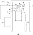
- FIG. 1 depicts a limit switch system 10 for an exemplary elevator system 12 having a hoistway 14 and an elevator car 16.
- the elevator car 16 is configured to travel in the hoistway 14 in the exemplary embodiment.
- the elevator car 16 is coupled to a counterweight 22 as understood by one having ordinary skill in the art.
- An elevator machine 20 is configured to move the elevator car 16 within the hoistway 14.
- the elevator machine 20 may include a motor, rotating machinery, and/or additional equipment that require periodic maintenance or inspection.
- the elevator system 12 of the FIG. 1 embodiment further includes a first limit device 28 and a second limit device 30 operably coupled to an inspection device 44 located on the top surface of the elevator car 16.
- the inspection device 44 is further coupled to the controller 18.
- the inspection device 44 includes a manually operated switch 48 in an embodiment, including without limitation one or more toggle switch(es), dial(s), button(s), touchpad(s), lever(s), or any other control, detection, or sensing interface known to a person having ordinary skill in the art.
- the inspection device 44 is configured to allow operation of the elevator car 16 in a normal state, as illustrated conceptually in FIG. 1 , and an inspection state, as illustrated conceptually in FIG. 2 .
- the elevator car 16 is controlled by the elevator controller 18 to travel within the hoistway 14 at a contracted elevator speed to allow passengers to travel within a building.
- the elevator car 16 is controlled, at a reduced speed, by an elevator mechanic from a top exterior surface 26 of the elevator car 16 using the inspection device 44.
- FIG. 1 illustrates a normal state of the limit switch system 10.
- the first limit device 28 senses or detects the presence of the elevator car 16 in the hoistway 14 and sends a first input signal to the controller 18, such as via signal line 32 in one non-limiting example, indicating that the elevator car 16 has reached the first location 34 in the hoistway 14.
- the controller 18 limits or stops the travel of the elevator car 16 upon receiving the first input signal by removing power to the elevator machine 20 and/or initiating a braking device on the elevator machine 20.
- the controller 18 initiates a car operation stop circuit to stop the elevator car 16 when the top exterior surface 26 is positioned within a certain level range with respect to the first location 34.
- the first limit device 28 is a switch, sensor, or detector that is positioned at the first location 34 in the hoistway 14 and is triggered by the elevator car 16.
- the first limit device 28 is a switch, sensor, or detector that is positioned on the elevator car 16 to determine its relative position.
- the various devices and methods used for sensing position, movement, and/or velocity, and such devices and methods form part of the present disclosure.
- the elevator car 18 is operating in the inspection state.
- the elevator car 16 is allowed to move or travel past the first limit device 28 to a second location 40 in the hoistway 14 until the elevator car 16 reaches the second limit device 30.
- the second limit device 30 senses or detects the presence of the elevator car 16 in the hoistway 14 and sends a second input signal, such as via signal line 46 in one non-limiting example, to the controller 18 indicating that the elevator car 16 has reached the second location 40 in the hoistway 14.
- the first location 34 is positioned at a vertical location below the second location 40.
- the controller 18 limits or stops the travel of the elevator car 16 upon receiving the second input signal such that the elevator car 16 does not travel higher than the second location 40.
- the controller 18 initiates a car operation stop circuit to stop the elevator car 16 when the top exterior surface 26 is positioned within a certain level range with respect to the second location 40.
- the first input signal and the second input signal are received by the controller 18 as separate signals.
- the second limit device 30 is a switch, sensor, or detector that is positioned at the second location 40 in the hoistway 14 and is triggered by the elevator car 16.
- the second limit device 30 is a switch, sensor, or detector that is positioned on the elevator car 16 to determine its relative position.
- a switch, sensor, or detector that is positioned on the elevator car 16 to determine its relative position.
- the elevator system 12 includes only a single limit device, which determines a location of the elevator car 16, such as the top exterior surface 26 in one non-limiting example, relative to the first location 34 and/or the second location 40.
- the single limit device includes a radar sensor, a laser range finder, a magnetometer, an accelerometer, or any one or more similar devices recognized by one having ordinary skill in the art as functioning to determine a location of the elevator car 16.
- the second location 40 is positioned to provide access to the elevator machine 20, in the inspection state, from the inspection area 24 of the elevator car 16.
- the inspection area 24 of the elevator car 16 in one embodiment includes the physical space capable of being occupied by a person standing on the top surface 26 of the elevator car 16.
- the inspection area 24 includes a volume of space within the hoistway 14 from 0 feet to 6 feet above the top surface 26 of the elevator car 16.
- the inspection area 24 includes a volume of space within the hoistway 14 from 0 feet to 4 feet above the top surface 26 of the elevator car 16.
- the inspection area 24 includes a volume of space within the hoistway 14 greater than 6 feet above the top surface 26 of the elevator car 16.
- the limit switch system 10 of the embodiments disclosed herein provide the ability for a mechanic or other person to access portions of the elevator system 12 that would be difficult to access from the inspection area 24 of the elevator car 16.
- the normal state is active and operational to limit the travel and positioning of the elevator car 16 to the first location 34.
- the mechanic or person positions themselves in the inspection area 24 of the elevator car 16 and operates the inspection device 44 to initiate the inspection state.
- the mechanic will obtain access to the hoistway 14 by entering a landing of the hoistway 14.
- the mechanic will then access the inspection device 44, such as a top of car inspection (TOCI) box in one non-limiting example.
- the mechanic will then activate the inspection state, thereby suspending ordinary operation.
- TOCI top of car inspection
- control of the inspection device 44 includes access to up, down, and common control buttons of the inspection device 44.
- the travel and positioning of the elevator car 16 in the inspection state may not exceed the second location 40.
- the person Upon completion of the inspection and/or maintenance, the person operates the inspection device 44 to return the limit switch system 10 to the normal state, and the elevator car 16 automatically descends or is controllable by the person to descend to the first location 34 or a location lower than the first location 34.
Landscapes
- Engineering & Computer Science (AREA)
- Automation & Control Theory (AREA)
- Computer Networks & Wireless Communication (AREA)
- Maintenance And Inspection Apparatuses For Elevators (AREA)
- Elevator Control (AREA)
Abstract
Description
- The present disclosure is generally related to elevator systems and, more particularly, to a limit switch system for an elevator system.
- Some machines, such as elevator systems, may require occasional or periodic inspection and/or maintenance of various systems and parts. Inspection and/or maintenance of an elevator system may be possible by positioning a mechanic or other person on the top exterior surface or portion of an elevator car. However, some elevator systems or parts, such as an elevator machine, are not immediately accessible for inspection from the top exterior surface of the elevator car due to a final limit control function of an elevator controller. The final limit control function may prevent the elevator car from ascending higher than a particular point in the elevator hoistway.
- Therefore, a need exists for a limit switch system that limits upward travel of the elevator car, but allows higher access to one or more portions of an elevator system for inspection and/or maintenance than the normal limit switch alone.
- In one embodiment of the present disclosure, an elevator system is provided having a hoistway, an elevator car to travel in the hoistway, and a limit device configured to determine a position of the elevator car at a location of the hoistway upon operating the elevator car in an inspection state.
- The limit device may include a first limit device configured to determine a position of the elevator car at a first location of the hoistway in a normal state and a second limit device configured to determine the position of the elevator car at a second location of the hoistway upon operating the elevator car in an inspection state. The first limit device may be activated and the second limit device may be deactivated in a normal state. The second limit device may be activated and the first limit device may be deactivated in the inspection state. The first location may be positioned below the second location. The elevator system may further include a controller connected to the first limit device and the second limit device and an inspection device connected to the controller, the first limit device, and the second limit device and configured to allow selection of the inspection state. The inspection device may include a manually operated switch. The first limit device and the second limit device may be connected to the controller through the inspection device. The elevator system may further include an elevator machine disposed in the hoistway, the second location positioned to provide access to the elevator machine from a top area of the elevator car.
- In an embodiment of the present disclosure, a limit switch system for an elevator is provided. The limit switch system includes a limit device configured to determine a position of the elevator car at a location of the hoistway upon selection of an inspection state.
- The limit device may include a first limit device configured to detect a position of an elevator car at a first location of a hoistway in a normal state and a second limit device configured to detect a position of the elevator car at a second location of the hoistway upon selection of an inspection state. The first limit device may be activated and the second limit device may be deactivated in a normal state. The second limit device may be activated and the first limit device may be deactivated in the inspection state. The first location may be positioned below the second location. The limit switch system may further include a controller connected to the first limit device and the second limit device and an inspection device connected to the controller, the first limit device, and the second limit device and configured to allow selection of the inspection state. The inspection device may include a manually operated switch. The first limit device and the second limit device may be connected to the controller through the inspection device.
- The embodiments and other features, advantages and disclosures contained herein, and the manner of attaining them, will become apparent and the present disclosure will be better understood by reference to the following description of various exemplary embodiments of the present disclosure taken in conjunction with the accompanying drawings, wherein:
-
FIG. 1 is a schematic side view of a limit switch system according to an embodiment of the present disclosure; and -
FIG. 2 is a schematic side view of a limit switch system according to an embodiment of the present disclosure. - For the purposes of promoting an understanding of the principles of the present disclosure, reference will now be made to the embodiments illustrated in the drawings, and specific language will be used to describe the same. It will nevertheless be understood that no limitation of the scope of this disclosure is thereby intended.
-
FIG. 1 depicts alimit switch system 10 for anexemplary elevator system 12 having ahoistway 14 and anelevator car 16. Theelevator car 16 is configured to travel in thehoistway 14 in the exemplary embodiment. In the embodiment illustrated inFIG. 1 , theelevator car 16 is coupled to acounterweight 22 as understood by one having ordinary skill in the art. Anelevator machine 20 is configured to move theelevator car 16 within thehoistway 14. Theelevator machine 20 may include a motor, rotating machinery, and/or additional equipment that require periodic maintenance or inspection. - The movement, positioning, or travel of the
elevator car 16 within thehoistway 14 is controlled by acontroller 18. As conceptually illustrated inFIG. 1 , theelevator system 12 of theFIG. 1 embodiment further includes afirst limit device 28 and asecond limit device 30 operably coupled to aninspection device 44 located on the top surface of theelevator car 16. Theinspection device 44 is further coupled to thecontroller 18. Theinspection device 44 includes a manually operatedswitch 48 in an embodiment, including without limitation one or more toggle switch(es), dial(s), button(s), touchpad(s), lever(s), or any other control, detection, or sensing interface known to a person having ordinary skill in the art. - The
inspection device 44 is configured to allow operation of theelevator car 16 in a normal state, as illustrated conceptually inFIG. 1 , and an inspection state, as illustrated conceptually inFIG. 2 . In the normal state illustrated inFIG. 1 , theelevator car 16 is controlled by theelevator controller 18 to travel within thehoistway 14 at a contracted elevator speed to allow passengers to travel within a building. In the inspection state illustrated inFIG. 2 , theelevator car 16 is controlled, at a reduced speed, by an elevator mechanic from a topexterior surface 26 of theelevator car 16 using theinspection device 44. -
FIG. 1 illustrates a normal state of thelimit switch system 10. When theelevator car 16 operates in the normal state and moves or travels to afirst location 34 in thehoistway 14, thefirst limit device 28 senses or detects the presence of theelevator car 16 in thehoistway 14 and sends a first input signal to thecontroller 18, such as viasignal line 32 in one non-limiting example, indicating that theelevator car 16 has reached thefirst location 34 in thehoistway 14. Thecontroller 18 limits or stops the travel of theelevator car 16 upon receiving the first input signal by removing power to theelevator machine 20 and/or initiating a braking device on theelevator machine 20. In one non-limiting example, thecontroller 18 initiates a car operation stop circuit to stop theelevator car 16 when the topexterior surface 26 is positioned within a certain level range with respect to thefirst location 34. One of ordinary skill will recognize the various mechanisms and methods for stopping or limiting travel of theelevator machine 20, and such mechanisms and methods form part of the present disclosure. In one embodiment, thefirst limit device 28 is a switch, sensor, or detector that is positioned at thefirst location 34 in thehoistway 14 and is triggered by theelevator car 16. In an additional embodiment, thefirst limit device 28 is a switch, sensor, or detector that is positioned on theelevator car 16 to determine its relative position. One of ordinary skill in the art will recognize the various devices and methods used for sensing position, movement, and/or velocity, and such devices and methods form part of the present disclosure. - Referring now to the embodiment of
FIG. 2 , theelevator car 18 is operating in the inspection state. In the inspection state, theelevator car 16 is allowed to move or travel past thefirst limit device 28 to asecond location 40 in thehoistway 14 until theelevator car 16 reaches thesecond limit device 30. Thesecond limit device 30 senses or detects the presence of theelevator car 16 in thehoistway 14 and sends a second input signal, such as viasignal line 46 in one non-limiting example, to thecontroller 18 indicating that theelevator car 16 has reached thesecond location 40 in thehoistway 14. In the embodiments ofFIGS. 1 and2 , thefirst location 34 is positioned at a vertical location below thesecond location 40. Thecontroller 18 limits or stops the travel of theelevator car 16 upon receiving the second input signal such that theelevator car 16 does not travel higher than thesecond location 40. In one non-limiting example, thecontroller 18 initiates a car operation stop circuit to stop theelevator car 16 when the topexterior surface 26 is positioned within a certain level range with respect to thesecond location 40. One of ordinary skill will recognize the various mechanisms and methods for stopping or limiting travel of theelevator machine 20, and such mechanisms and methods form part of the present disclosure. In an embodiment, the first input signal and the second input signal are received by thecontroller 18 as separate signals. In one embodiment, thesecond limit device 30 is a switch, sensor, or detector that is positioned at thesecond location 40 in thehoistway 14 and is triggered by theelevator car 16. In an additional embodiment, thesecond limit device 30 is a switch, sensor, or detector that is positioned on theelevator car 16 to determine its relative position. One of ordinary skill in the art will recognize the various devices and methods used for sensing position, movement, and/or velocity, and such devices and methods form part of the present disclosure. - In an embodiment, the
elevator system 12 includes only a single limit device, which determines a location of theelevator car 16, such as the topexterior surface 26 in one non-limiting example, relative to thefirst location 34 and/or thesecond location 40. The single limit device includes a radar sensor, a laser range finder, a magnetometer, an accelerometer, or any one or more similar devices recognized by one having ordinary skill in the art as functioning to determine a location of theelevator car 16. - In the exemplary embodiment of
FIG. 2 , thesecond location 40 is positioned to provide access to theelevator machine 20, in the inspection state, from theinspection area 24 of theelevator car 16. Theinspection area 24 of theelevator car 16 in one embodiment includes the physical space capable of being occupied by a person standing on thetop surface 26 of theelevator car 16. In an embodiment, theinspection area 24 includes a volume of space within thehoistway 14 from 0 feet to 6 feet above thetop surface 26 of theelevator car 16. In another embodiment, theinspection area 24 includes a volume of space within thehoistway 14 from 0 feet to 4 feet above thetop surface 26 of theelevator car 16. In another embodiment, theinspection area 24 includes a volume of space within thehoistway 14 greater than 6 feet above thetop surface 26 of theelevator car 16. - The
limit switch system 10 of the embodiments disclosed herein provide the ability for a mechanic or other person to access portions of theelevator system 12 that would be difficult to access from theinspection area 24 of theelevator car 16. During normal elevator operation, the normal state is active and operational to limit the travel and positioning of theelevator car 16 to thefirst location 34. When maintenance and/or inspection is required, the mechanic or person positions themselves in theinspection area 24 of theelevator car 16 and operates theinspection device 44 to initiate the inspection state. Specifically, in an embodiment, the mechanic will obtain access to thehoistway 14 by entering a landing of thehoistway 14. The mechanic will then access theinspection device 44, such as a top of car inspection (TOCI) box in one non-limiting example. The mechanic will then activate the inspection state, thereby suspending ordinary operation. Upon activation of the inspection state, theelevator car 16 is controllable by the person up to thesecond location 40. In one non-limiting example, control of theinspection device 44 includes access to up, down, and common control buttons of theinspection device 44. The travel and positioning of theelevator car 16 in the inspection state may not exceed thesecond location 40. - Upon completion of the inspection and/or maintenance, the person operates the
inspection device 44 to return thelimit switch system 10 to the normal state, and theelevator car 16 automatically descends or is controllable by the person to descend to thefirst location 34 or a location lower than thefirst location 34. - While the disclosure has been illustrated and described in detail in the drawings and foregoing description, the same is to be considered as illustrative and not restrictive in character, it being understood that only certain embodiments have been shown and described and that all changes and modifications that come within the spirit of the disclosure are desired to be protected.
Claims (15)
- An elevator system comprising:a hoistway;an elevator car to travel in the hoistway; anda limit device configured to determine a position of the elevator car at a location of the hoistway upon operating the elevator car in an inspection state.
- The elevator system of claim 1, wherein the limit device includes a first limit device configured to determine a position of the elevator car at a first location of the hoistway in a normal state and a second limit device configured to determine the position of the elevator car at a second location of the hoistway upon operating the elevator car in an inspection state.
- The elevator system of claim 2, wherein the first limit device is activated and the second limit device is deactivated in a normal state.
- The elevator system of claim 2 or 3, wherein the second limit device is activated and the first limit device is deactivated in the inspection state.
- The elevator system of any of claims 2-4, wherein the first location is positioned below the second location.
- The elevator system of any of claims 2-5, further comprising:a controller connected to the first limit device and the second limit device; andan inspection device connected to the controller, the first limit device, and the second limit device and configured to allow selection of the inspection state;and optionally wherein the inspection device includes a manually operated switch.
- The elevator system of claim 6, wherein the first limit device and the second limit device are connected to the controller through the inspection device.
- The elevator system of any of claims 2-7, further comprising an elevator machine disposed in the hoistway, the second location positioned to provide access to the elevator machine from a top area of the elevator car.
- A limit switch system for an elevator, the limit switch system comprising:a limit device configured to determine a position of the elevator car at a location of the hoistway upon selection of an inspection state.
- The limit switch system of claim 9, wherein the limit device includes a first limit device configured to detect a position of an elevator car at a first location of a hoistway in a normal state and a second limit device configured to detect a position of the elevator car at a second location of the hoistway upon selection of an inspection state.
- The limit switch system of claim 10, wherein the first limit device is activated and the second limit device is deactivated in a normal state.
- The limit switch system of claim 10 or 11, wherein the second limit device is activated and the first limit device is deactivated in the inspection state.
- The limit switch system of any of claims 10-12, wherein the first location is positioned below the second location.
- The limit switch system of any of claims 10-13, further comprising:a controller connected to the first limit device and the second limit device; andan inspection device connected to the controller, the first limit device, and the second limit device and configured to allow selection of the inspection state;optionally wherein the inspection device includes a manually operated switch.
- The limit switch system of claim 14, wherein the first limit device and the second limit device are connected to the controller through the inspection device.
Applications Claiming Priority (1)
| Application Number | Priority Date | Filing Date | Title |
|---|---|---|---|
| US15/199,814 US10457522B2 (en) | 2016-06-30 | 2016-06-30 | Limit switch system including first limit device and second limit device |
Publications (2)
| Publication Number | Publication Date |
|---|---|
| EP3266735A1 true EP3266735A1 (en) | 2018-01-10 |
| EP3266735B1 EP3266735B1 (en) | 2022-05-11 |
Family
ID=59269967
Family Applications (1)
| Application Number | Title | Priority Date | Filing Date |
|---|---|---|---|
| EP17179208.8A Active EP3266735B1 (en) | 2016-06-30 | 2017-06-30 | Limit switch system |
Country Status (3)
| Country | Link |
|---|---|
| US (1) | US10457522B2 (en) |
| EP (1) | EP3266735B1 (en) |
| CN (1) | CN107555288B (en) |
Cited By (1)
| Publication number | Priority date | Publication date | Assignee | Title |
|---|---|---|---|---|
| WO2022063656A1 (en) * | 2020-09-22 | 2022-03-31 | Elgo Batscale Ag | Control module for an elevator system |
Families Citing this family (3)
| Publication number | Priority date | Publication date | Assignee | Title |
|---|---|---|---|---|
| US10457522B2 (en) | 2016-06-30 | 2019-10-29 | Otis Elevator Company | Limit switch system including first limit device and second limit device |
| ES2914319T3 (en) * | 2019-07-05 | 2022-06-09 | Otis Elevator Co | Elevator Assembly with Counterweight Lock Stop |
| USD952982S1 (en) * | 2019-09-13 | 2022-05-24 | Harmar Mobility, Llc | Vertical platform lift |
Citations (3)
| Publication number | Priority date | Publication date | Assignee | Title |
|---|---|---|---|---|
| JP2002114462A (en) * | 2000-10-11 | 2002-04-16 | Mitsubishi Electric Building Techno Service Co Ltd | Maintenance and inspection time operation device of elevator |
| EP1475342A1 (en) * | 2003-05-07 | 2004-11-10 | Inventio Ag | Device to create a temporary working space for elevators |
| EP2033927A1 (en) * | 2006-06-30 | 2009-03-11 | Otis Elevator Company | Elevator having a shallow pit and/or a low overhead |
Family Cites Families (32)
| Publication number | Priority date | Publication date | Assignee | Title |
|---|---|---|---|---|
| JPH0346985A (en) | 1989-07-12 | 1991-02-28 | Hitachi Ltd | Maintenance operating device for elevator |
| JP2001106447A (en) | 1999-10-04 | 2001-04-17 | Hitachi Building Systems Co Ltd | Elevator limit switch |
| DE10108772A1 (en) | 2001-02-23 | 2002-11-21 | Otis Elevator Co | Elevator safety device |
| US7258202B1 (en) * | 2004-05-10 | 2007-08-21 | Inventio Ag | Creation of temporary safety spaces for elevators |
| JP4742591B2 (en) | 2005-01-19 | 2011-08-10 | 三菱電機株式会社 | Elevator terminal safety device |
| JP2007153476A (en) | 2005-12-01 | 2007-06-21 | Mitsubishi Electric Building Techno Service Co Ltd | Terminal position manual operation device for elevator |
| EP2035313B1 (en) * | 2006-06-30 | 2010-11-03 | Otis Elevator Company | Safety device for securing minimum spaces at the top or bottom of an elevator shaft being inspected, and elevator having such safety devices |
| SG139660A1 (en) | 2006-07-26 | 2008-02-29 | Inventio Ag | Method of controlling access to an elevator car |
| FI125141B (en) * | 2007-01-03 | 2015-06-15 | Kone Corp | Elevator safety device |
| FI20070486A7 (en) | 2007-01-03 | 2008-07-04 | Kone Corp | Elevator security system |
| CN101077749B (en) * | 2007-04-29 | 2010-07-28 | 广州日立电梯有限公司 | Elevator pit maintenance inspection protection system |
| CN201390579Y (en) * | 2009-01-13 | 2010-01-27 | 西子奥的斯电梯有限公司 | Elevator limiting device |
| CN201525681U (en) * | 2009-10-21 | 2010-07-14 | 允成机电科技(上海)有限公司 | Knapsack-type home elevator mechanical stopping device |
| JP2011178496A (en) | 2010-02-26 | 2011-09-15 | Toshiba Elevator Co Ltd | Control device for elevator |
| JP2012051708A (en) | 2010-09-02 | 2012-03-15 | Toshiba Elevator Co Ltd | Elevator device |
| CN103068710B (en) | 2010-10-01 | 2015-07-22 | 三菱电机株式会社 | Elevator operation mode switching system |
| CN102344065A (en) | 2011-06-28 | 2012-02-08 | 苏州新达电扶梯部件有限公司 | Ultimate limiting device |
| JP2013010604A (en) | 2011-06-29 | 2013-01-17 | Hitachi Ltd | Elevator apparatus |
| EP2604565A1 (en) | 2011-12-14 | 2013-06-19 | Inventio AG | Lift system with upper limit of the maintenance area that can be raised |
| CN202744128U (en) | 2012-07-23 | 2013-02-20 | 杭州西奥电梯有限公司 | Protection device for high-speed elevator end station |
| CN104684834B (en) * | 2012-09-25 | 2017-10-20 | 奥的斯电梯公司 | Low top or the indemnifying measure of low pit elevator |
| JP5962416B2 (en) | 2012-10-10 | 2016-08-03 | 三菱電機ビルテクノサービス株式会社 | Elevator safety protective device detection system |
| EP2727871B1 (en) * | 2012-10-30 | 2016-03-23 | KONE Corporation | An elevator and a method |
| FI125118B (en) * | 2013-01-07 | 2015-06-15 | Kone Corp | Elevator |
| CN103663007B (en) * | 2013-12-17 | 2015-08-12 | 叶荣伟 | A kind of energy-saving traction elevator and power-economizing method thereof |
| CN203976151U (en) | 2014-05-27 | 2014-12-03 | 姚长云 | A kind of normal open switch that can distinguish the short circuit Room, gate lock on sedan-chair top |
| CN204150836U (en) | 2014-09-22 | 2015-02-11 | 歌拉瑞电梯有限公司 | A kind of cage top overhauling automatic switch |
| EP3012217B8 (en) * | 2014-10-21 | 2017-08-02 | KONE Corporation | Safety system for elevator |
| EP3365260B1 (en) * | 2015-10-22 | 2020-09-23 | Kone Corporation | Elevator with a safety arrangement and method for creating a safe working space in the upper part of the elevator shaft |
| US10457522B2 (en) | 2016-06-30 | 2019-10-29 | Otis Elevator Company | Limit switch system including first limit device and second limit device |
| EP3360731B1 (en) * | 2017-02-10 | 2020-02-05 | DURA Operating, LLC | Roof rail |
| EP3401260B1 (en) * | 2017-05-12 | 2023-08-09 | Otis Elevator Company | Elevator overrun systems |
-
2016
- 2016-06-30 US US15/199,814 patent/US10457522B2/en active Active
-
2017
- 2017-06-29 CN CN201710514458.2A patent/CN107555288B/en active Active
- 2017-06-30 EP EP17179208.8A patent/EP3266735B1/en active Active
Patent Citations (3)
| Publication number | Priority date | Publication date | Assignee | Title |
|---|---|---|---|---|
| JP2002114462A (en) * | 2000-10-11 | 2002-04-16 | Mitsubishi Electric Building Techno Service Co Ltd | Maintenance and inspection time operation device of elevator |
| EP1475342A1 (en) * | 2003-05-07 | 2004-11-10 | Inventio Ag | Device to create a temporary working space for elevators |
| EP2033927A1 (en) * | 2006-06-30 | 2009-03-11 | Otis Elevator Company | Elevator having a shallow pit and/or a low overhead |
Cited By (1)
| Publication number | Priority date | Publication date | Assignee | Title |
|---|---|---|---|---|
| WO2022063656A1 (en) * | 2020-09-22 | 2022-03-31 | Elgo Batscale Ag | Control module for an elevator system |
Also Published As
| Publication number | Publication date |
|---|---|
| CN107555288B (en) | 2020-09-04 |
| CN107555288A (en) | 2018-01-09 |
| US10457522B2 (en) | 2019-10-29 |
| US20180002140A1 (en) | 2018-01-04 |
| EP3266735B1 (en) | 2022-05-11 |
Similar Documents
| Publication | Publication Date | Title |
|---|---|---|
| EP3357851B1 (en) | Mechanism for improving safety for an elevator system | |
| JP6294335B2 (en) | Elevator with variable length shock absorber | |
| US10457522B2 (en) | Limit switch system including first limit device and second limit device | |
| EP2389333B1 (en) | Elevator safety device | |
| CN108529369B (en) | Elevator maintenance work auxiliary system | |
| KR102054600B1 (en) | Safety device of a lift system | |
| CN108217360B (en) | Elevator safety system and method of operating an elevator system | |
| JP5741746B2 (en) | Elevator system | |
| JP2015013731A5 (en) | ||
| CN108529368B (en) | Elevator maintenance support system | |
| JPWO2011111096A1 (en) | Elevator with safe position sensor | |
| CN104229571B (en) | Elevator | |
| JP6272201B2 (en) | elevator | |
| EP2838827B1 (en) | Testing apparatus and safety arrangement | |
| EP3159295A1 (en) | Service alarm device for an elevator system | |
| KR20170110130A (en) | Roofless elevator control system | |
| EP2765109A2 (en) | Control system of the position, speed limit and uncontrolled movements of the cabin or counterweight of an elevator | |
| EP3187449A1 (en) | Mechanism for improving safety for an elevator system | |
| JP6021886B2 (en) | Elevator control device | |
| EP4400466B1 (en) | Emergency stop system for elevator | |
| JP2012512116A (en) | Elevator brake control | |
| KR102265012B1 (en) | Forced deceleration control apparatus and method of variable speed elevator | |
| WO2019130407A1 (en) | Elevator and method for protecting against elevator moving with door open | |
| EP3643670B1 (en) | Vertical bounce detection and mitigation | |
| JP7156044B2 (en) | elevator equipment |
Legal Events
| Date | Code | Title | Description |
|---|---|---|---|
| PUAI | Public reference made under article 153(3) epc to a published international application that has entered the european phase |
Free format text: ORIGINAL CODE: 0009012 |
|
| STAA | Information on the status of an ep patent application or granted ep patent |
Free format text: STATUS: THE APPLICATION HAS BEEN PUBLISHED |
|
| AK | Designated contracting states |
Kind code of ref document: A1 Designated state(s): AL AT BE BG CH CY CZ DE DK EE ES FI FR GB GR HR HU IE IS IT LI LT LU LV MC MK MT NL NO PL PT RO RS SE SI SK SM TR |
|
| AX | Request for extension of the european patent |
Extension state: BA ME |
|
| STAA | Information on the status of an ep patent application or granted ep patent |
Free format text: STATUS: REQUEST FOR EXAMINATION WAS MADE |
|
| 17P | Request for examination filed |
Effective date: 20180710 |
|
| RBV | Designated contracting states (corrected) |
Designated state(s): AL AT BE BG CH CY CZ DE DK EE ES FI FR GB GR HR HU IE IS IT LI LT LU LV MC MK MT NL NO PL PT RO RS SE SI SK SM TR |
|
| STAA | Information on the status of an ep patent application or granted ep patent |
Free format text: STATUS: EXAMINATION IS IN PROGRESS |
|
| 17Q | First examination report despatched |
Effective date: 20191024 |
|
| GRAP | Despatch of communication of intention to grant a patent |
Free format text: ORIGINAL CODE: EPIDOSNIGR1 |
|
| STAA | Information on the status of an ep patent application or granted ep patent |
Free format text: STATUS: GRANT OF PATENT IS INTENDED |
|
| RAP3 | Party data changed (applicant data changed or rights of an application transferred) |
Owner name: OTIS ELEVATOR COMPANY |
|
| INTG | Intention to grant announced |
Effective date: 20211221 |
|
| GRAS | Grant fee paid |
Free format text: ORIGINAL CODE: EPIDOSNIGR3 |
|
| GRAA | (expected) grant |
Free format text: ORIGINAL CODE: 0009210 |
|
| STAA | Information on the status of an ep patent application or granted ep patent |
Free format text: STATUS: THE PATENT HAS BEEN GRANTED |
|
| AK | Designated contracting states |
Kind code of ref document: B1 Designated state(s): AL AT BE BG CH CY CZ DE DK EE ES FI FR GB GR HR HU IE IS IT LI LT LU LV MC MK MT NL NO PL PT RO RS SE SI SK SM TR |
|
| REG | Reference to a national code |
Ref country code: GB Ref legal event code: FG4D |
|
| REG | Reference to a national code |
Ref country code: CH Ref legal event code: EP |
|
| REG | Reference to a national code |
Ref country code: AT Ref legal event code: REF Ref document number: 1491282 Country of ref document: AT Kind code of ref document: T Effective date: 20220515 |
|
| REG | Reference to a national code |
Ref country code: DE Ref legal event code: R096 Ref document number: 602017057243 Country of ref document: DE |
|
| REG | Reference to a national code |
Ref country code: IE Ref legal event code: FG4D |
|
| REG | Reference to a national code |
Ref country code: LT Ref legal event code: MG9D |
|
| REG | Reference to a national code |
Ref country code: NL Ref legal event code: MP Effective date: 20220511 |
|
| REG | Reference to a national code |
Ref country code: AT Ref legal event code: MK05 Ref document number: 1491282 Country of ref document: AT Kind code of ref document: T Effective date: 20220511 |
|
| PG25 | Lapsed in a contracting state [announced via postgrant information from national office to epo] |
Ref country code: SE Free format text: LAPSE BECAUSE OF FAILURE TO SUBMIT A TRANSLATION OF THE DESCRIPTION OR TO PAY THE FEE WITHIN THE PRESCRIBED TIME-LIMIT Effective date: 20220511 Ref country code: PT Free format text: LAPSE BECAUSE OF FAILURE TO SUBMIT A TRANSLATION OF THE DESCRIPTION OR TO PAY THE FEE WITHIN THE PRESCRIBED TIME-LIMIT Effective date: 20220912 Ref country code: NO Free format text: LAPSE BECAUSE OF FAILURE TO SUBMIT A TRANSLATION OF THE DESCRIPTION OR TO PAY THE FEE WITHIN THE PRESCRIBED TIME-LIMIT Effective date: 20220811 Ref country code: NL Free format text: LAPSE BECAUSE OF FAILURE TO SUBMIT A TRANSLATION OF THE DESCRIPTION OR TO PAY THE FEE WITHIN THE PRESCRIBED TIME-LIMIT Effective date: 20220511 Ref country code: LT Free format text: LAPSE BECAUSE OF FAILURE TO SUBMIT A TRANSLATION OF THE DESCRIPTION OR TO PAY THE FEE WITHIN THE PRESCRIBED TIME-LIMIT Effective date: 20220511 Ref country code: HR Free format text: LAPSE BECAUSE OF FAILURE TO SUBMIT A TRANSLATION OF THE DESCRIPTION OR TO PAY THE FEE WITHIN THE PRESCRIBED TIME-LIMIT Effective date: 20220511 Ref country code: GR Free format text: LAPSE BECAUSE OF FAILURE TO SUBMIT A TRANSLATION OF THE DESCRIPTION OR TO PAY THE FEE WITHIN THE PRESCRIBED TIME-LIMIT Effective date: 20220812 Ref country code: FI Free format text: LAPSE BECAUSE OF FAILURE TO SUBMIT A TRANSLATION OF THE DESCRIPTION OR TO PAY THE FEE WITHIN THE PRESCRIBED TIME-LIMIT Effective date: 20220511 Ref country code: ES Free format text: LAPSE BECAUSE OF FAILURE TO SUBMIT A TRANSLATION OF THE DESCRIPTION OR TO PAY THE FEE WITHIN THE PRESCRIBED TIME-LIMIT Effective date: 20220511 Ref country code: BG Free format text: LAPSE BECAUSE OF FAILURE TO SUBMIT A TRANSLATION OF THE DESCRIPTION OR TO PAY THE FEE WITHIN THE PRESCRIBED TIME-LIMIT Effective date: 20220811 Ref country code: AT Free format text: LAPSE BECAUSE OF FAILURE TO SUBMIT A TRANSLATION OF THE DESCRIPTION OR TO PAY THE FEE WITHIN THE PRESCRIBED TIME-LIMIT Effective date: 20220511 |
|
| PG25 | Lapsed in a contracting state [announced via postgrant information from national office to epo] |
Ref country code: RS Free format text: LAPSE BECAUSE OF FAILURE TO SUBMIT A TRANSLATION OF THE DESCRIPTION OR TO PAY THE FEE WITHIN THE PRESCRIBED TIME-LIMIT Effective date: 20220511 Ref country code: PL Free format text: LAPSE BECAUSE OF FAILURE TO SUBMIT A TRANSLATION OF THE DESCRIPTION OR TO PAY THE FEE WITHIN THE PRESCRIBED TIME-LIMIT Effective date: 20220511 Ref country code: LV Free format text: LAPSE BECAUSE OF FAILURE TO SUBMIT A TRANSLATION OF THE DESCRIPTION OR TO PAY THE FEE WITHIN THE PRESCRIBED TIME-LIMIT Effective date: 20220511 Ref country code: IS Free format text: LAPSE BECAUSE OF FAILURE TO SUBMIT A TRANSLATION OF THE DESCRIPTION OR TO PAY THE FEE WITHIN THE PRESCRIBED TIME-LIMIT Effective date: 20220911 |
|
| PG25 | Lapsed in a contracting state [announced via postgrant information from national office to epo] |
Ref country code: SM Free format text: LAPSE BECAUSE OF FAILURE TO SUBMIT A TRANSLATION OF THE DESCRIPTION OR TO PAY THE FEE WITHIN THE PRESCRIBED TIME-LIMIT Effective date: 20220511 Ref country code: SK Free format text: LAPSE BECAUSE OF FAILURE TO SUBMIT A TRANSLATION OF THE DESCRIPTION OR TO PAY THE FEE WITHIN THE PRESCRIBED TIME-LIMIT Effective date: 20220511 Ref country code: RO Free format text: LAPSE BECAUSE OF FAILURE TO SUBMIT A TRANSLATION OF THE DESCRIPTION OR TO PAY THE FEE WITHIN THE PRESCRIBED TIME-LIMIT Effective date: 20220511 Ref country code: EE Free format text: LAPSE BECAUSE OF FAILURE TO SUBMIT A TRANSLATION OF THE DESCRIPTION OR TO PAY THE FEE WITHIN THE PRESCRIBED TIME-LIMIT Effective date: 20220511 Ref country code: DK Free format text: LAPSE BECAUSE OF FAILURE TO SUBMIT A TRANSLATION OF THE DESCRIPTION OR TO PAY THE FEE WITHIN THE PRESCRIBED TIME-LIMIT Effective date: 20220511 Ref country code: CZ Free format text: LAPSE BECAUSE OF FAILURE TO SUBMIT A TRANSLATION OF THE DESCRIPTION OR TO PAY THE FEE WITHIN THE PRESCRIBED TIME-LIMIT Effective date: 20220511 |
|
| REG | Reference to a national code |
Ref country code: CH Ref legal event code: PL |
|
| REG | Reference to a national code |
Ref country code: DE Ref legal event code: R097 Ref document number: 602017057243 Country of ref document: DE |
|
| REG | Reference to a national code |
Ref country code: BE Ref legal event code: MM Effective date: 20220630 |
|
| PG25 | Lapsed in a contracting state [announced via postgrant information from national office to epo] |
Ref country code: MC Free format text: LAPSE BECAUSE OF FAILURE TO SUBMIT A TRANSLATION OF THE DESCRIPTION OR TO PAY THE FEE WITHIN THE PRESCRIBED TIME-LIMIT Effective date: 20220511 |
|
| PLBE | No opposition filed within time limit |
Free format text: ORIGINAL CODE: 0009261 |
|
| STAA | Information on the status of an ep patent application or granted ep patent |
Free format text: STATUS: NO OPPOSITION FILED WITHIN TIME LIMIT |
|
| PG25 | Lapsed in a contracting state [announced via postgrant information from national office to epo] |
Ref country code: AL Free format text: LAPSE BECAUSE OF FAILURE TO SUBMIT A TRANSLATION OF THE DESCRIPTION OR TO PAY THE FEE WITHIN THE PRESCRIBED TIME-LIMIT Effective date: 20220511 |
|
| 26N | No opposition filed |
Effective date: 20230214 |
|
| GBPC | Gb: european patent ceased through non-payment of renewal fee |
Effective date: 20220811 |
|
| PG25 | Lapsed in a contracting state [announced via postgrant information from national office to epo] |
Ref country code: LU Free format text: LAPSE BECAUSE OF NON-PAYMENT OF DUE FEES Effective date: 20220630 Ref country code: LI Free format text: LAPSE BECAUSE OF NON-PAYMENT OF DUE FEES Effective date: 20220630 Ref country code: IE Free format text: LAPSE BECAUSE OF NON-PAYMENT OF DUE FEES Effective date: 20220630 Ref country code: CH Free format text: LAPSE BECAUSE OF NON-PAYMENT OF DUE FEES Effective date: 20220630 |
|
| PG25 | Lapsed in a contracting state [announced via postgrant information from national office to epo] |
Ref country code: SI Free format text: LAPSE BECAUSE OF FAILURE TO SUBMIT A TRANSLATION OF THE DESCRIPTION OR TO PAY THE FEE WITHIN THE PRESCRIBED TIME-LIMIT Effective date: 20220511 Ref country code: BE Free format text: LAPSE BECAUSE OF NON-PAYMENT OF DUE FEES Effective date: 20220630 |
|
| PG25 | Lapsed in a contracting state [announced via postgrant information from national office to epo] |
Ref country code: GB Free format text: LAPSE BECAUSE OF NON-PAYMENT OF DUE FEES Effective date: 20220811 |
|
| PG25 | Lapsed in a contracting state [announced via postgrant information from national office to epo] |
Ref country code: IT Free format text: LAPSE BECAUSE OF FAILURE TO SUBMIT A TRANSLATION OF THE DESCRIPTION OR TO PAY THE FEE WITHIN THE PRESCRIBED TIME-LIMIT Effective date: 20220511 |
|
| PG25 | Lapsed in a contracting state [announced via postgrant information from national office to epo] |
Ref country code: HU Free format text: LAPSE BECAUSE OF FAILURE TO SUBMIT A TRANSLATION OF THE DESCRIPTION OR TO PAY THE FEE WITHIN THE PRESCRIBED TIME-LIMIT; INVALID AB INITIO Effective date: 20170630 |
|
| PG25 | Lapsed in a contracting state [announced via postgrant information from national office to epo] |
Ref country code: MK Free format text: LAPSE BECAUSE OF FAILURE TO SUBMIT A TRANSLATION OF THE DESCRIPTION OR TO PAY THE FEE WITHIN THE PRESCRIBED TIME-LIMIT Effective date: 20220511 Ref country code: CY Free format text: LAPSE BECAUSE OF FAILURE TO SUBMIT A TRANSLATION OF THE DESCRIPTION OR TO PAY THE FEE WITHIN THE PRESCRIBED TIME-LIMIT Effective date: 20220511 |
|
| PG25 | Lapsed in a contracting state [announced via postgrant information from national office to epo] |
Ref country code: TR Free format text: LAPSE BECAUSE OF FAILURE TO SUBMIT A TRANSLATION OF THE DESCRIPTION OR TO PAY THE FEE WITHIN THE PRESCRIBED TIME-LIMIT Effective date: 20220511 |
|
| PG25 | Lapsed in a contracting state [announced via postgrant information from national office to epo] |
Ref country code: MT Free format text: LAPSE BECAUSE OF FAILURE TO SUBMIT A TRANSLATION OF THE DESCRIPTION OR TO PAY THE FEE WITHIN THE PRESCRIBED TIME-LIMIT Effective date: 20220511 |
|
| PG25 | Lapsed in a contracting state [announced via postgrant information from national office to epo] |
Ref country code: BG Free format text: LAPSE BECAUSE OF FAILURE TO SUBMIT A TRANSLATION OF THE DESCRIPTION OR TO PAY THE FEE WITHIN THE PRESCRIBED TIME-LIMIT Effective date: 20220511 |
|
| PG25 | Lapsed in a contracting state [announced via postgrant information from national office to epo] |
Ref country code: BG Free format text: LAPSE BECAUSE OF FAILURE TO SUBMIT A TRANSLATION OF THE DESCRIPTION OR TO PAY THE FEE WITHIN THE PRESCRIBED TIME-LIMIT Effective date: 20220511 |
|
| PGFP | Annual fee paid to national office [announced via postgrant information from national office to epo] |
Ref country code: DE Payment date: 20250520 Year of fee payment: 9 |
|
| PGFP | Annual fee paid to national office [announced via postgrant information from national office to epo] |
Ref country code: FR Payment date: 20250520 Year of fee payment: 9 |