EP3401260B1 - Elevator overrun systems - Google Patents
Elevator overrun systems Download PDFInfo
- Publication number
- EP3401260B1 EP3401260B1 EP17305541.9A EP17305541A EP3401260B1 EP 3401260 B1 EP3401260 B1 EP 3401260B1 EP 17305541 A EP17305541 A EP 17305541A EP 3401260 B1 EP3401260 B1 EP 3401260B1
- Authority
- EP
- European Patent Office
- Prior art keywords
- elevator
- car
- level
- overrun
- elevator car
- Prior art date
- Legal status (The legal status is an assumption and is not a legal conclusion. Google has not performed a legal analysis and makes no representation as to the accuracy of the status listed.)
- Active
Links
- 238000012423 maintenance Methods 0.000 claims description 42
- 230000033001 locomotion Effects 0.000 claims description 32
- 238000000034 method Methods 0.000 claims description 11
- 230000007246 mechanism Effects 0.000 description 5
- 230000008569 process Effects 0.000 description 5
- 230000001960 triggered effect Effects 0.000 description 5
- 230000006378 damage Effects 0.000 description 4
- 230000003993 interaction Effects 0.000 description 4
- 239000006096 absorbing agent Substances 0.000 description 3
- 230000035939 shock Effects 0.000 description 3
- 230000008093 supporting effect Effects 0.000 description 3
- 229910000831 Steel Inorganic materials 0.000 description 2
- 208000027418 Wounds and injury Diseases 0.000 description 2
- 238000010276 construction Methods 0.000 description 2
- 230000000977 initiatory effect Effects 0.000 description 2
- 208000014674 injury Diseases 0.000 description 2
- 238000009434 installation Methods 0.000 description 2
- 239000010959 steel Substances 0.000 description 2
- 230000001133 acceleration Effects 0.000 description 1
- 230000009471 action Effects 0.000 description 1
- 230000004913 activation Effects 0.000 description 1
- 230000008859 change Effects 0.000 description 1
- 238000004891 communication Methods 0.000 description 1
- 230000006835 compression Effects 0.000 description 1
- 238000007906 compression Methods 0.000 description 1
- 230000009849 deactivation Effects 0.000 description 1
- 230000000881 depressing effect Effects 0.000 description 1
- 230000001976 improved effect Effects 0.000 description 1
- 230000002452 interceptive effect Effects 0.000 description 1
- 239000000463 material Substances 0.000 description 1
- 230000003287 optical effect Effects 0.000 description 1
- 230000008439 repair process Effects 0.000 description 1
- 230000000630 rising effect Effects 0.000 description 1
- 230000003068 static effect Effects 0.000 description 1
- 238000003466 welding Methods 0.000 description 1
Images


Classifications
-
- B—PERFORMING OPERATIONS; TRANSPORTING
- B66—HOISTING; LIFTING; HAULING
- B66B—ELEVATORS; ESCALATORS OR MOVING WALKWAYS
- B66B5/00—Applications of checking, fault-correcting, or safety devices in elevators
- B66B5/0087—Devices facilitating maintenance, repair or inspection tasks
-
- B—PERFORMING OPERATIONS; TRANSPORTING
- B66—HOISTING; LIFTING; HAULING
- B66B—ELEVATORS; ESCALATORS OR MOVING WALKWAYS
- B66B5/00—Applications of checking, fault-correcting, or safety devices in elevators
- B66B5/0043—Devices enhancing safety during maintenance
- B66B5/005—Safety of maintenance personnel
-
- B—PERFORMING OPERATIONS; TRANSPORTING
- B66—HOISTING; LIFTING; HAULING
- B66B—ELEVATORS; ESCALATORS OR MOVING WALKWAYS
- B66B5/00—Applications of checking, fault-correcting, or safety devices in elevators
- B66B5/02—Applications of checking, fault-correcting, or safety devices in elevators responsive to abnormal operating conditions
- B66B5/04—Applications of checking, fault-correcting, or safety devices in elevators responsive to abnormal operating conditions for detecting excessive speed
- B66B5/044—Mechanical overspeed governors
-
- B—PERFORMING OPERATIONS; TRANSPORTING
- B66—HOISTING; LIFTING; HAULING
- B66B—ELEVATORS; ESCALATORS OR MOVING WALKWAYS
- B66B1/00—Control systems of elevators in general
- B66B1/24—Control systems with regulation, i.e. with retroactive action, for influencing travelling speed, acceleration, or deceleration
- B66B1/28—Control systems with regulation, i.e. with retroactive action, for influencing travelling speed, acceleration, or deceleration electrical
-
- B—PERFORMING OPERATIONS; TRANSPORTING
- B66—HOISTING; LIFTING; HAULING
- B66B—ELEVATORS; ESCALATORS OR MOVING WALKWAYS
- B66B17/00—Hoistway equipment
- B66B17/12—Counterpoises
-
- B—PERFORMING OPERATIONS; TRANSPORTING
- B66—HOISTING; LIFTING; HAULING
- B66B—ELEVATORS; ESCALATORS OR MOVING WALKWAYS
- B66B5/00—Applications of checking, fault-correcting, or safety devices in elevators
- B66B5/0043—Devices enhancing safety during maintenance
- B66B5/005—Safety of maintenance personnel
- B66B5/0056—Safety of maintenance personnel by preventing crushing
-
- B—PERFORMING OPERATIONS; TRANSPORTING
- B66—HOISTING; LIFTING; HAULING
- B66B—ELEVATORS; ESCALATORS OR MOVING WALKWAYS
- B66B5/00—Applications of checking, fault-correcting, or safety devices in elevators
- B66B5/28—Buffer-stops for cars, cages, or skips
-
- B—PERFORMING OPERATIONS; TRANSPORTING
- B66—HOISTING; LIFTING; HAULING
- B66B—ELEVATORS; ESCALATORS OR MOVING WALKWAYS
- B66B5/00—Applications of checking, fault-correcting, or safety devices in elevators
- B66B5/28—Buffer-stops for cars, cages, or skips
- B66B5/282—Structure thereof
-
- B—PERFORMING OPERATIONS; TRANSPORTING
- B66—HOISTING; LIFTING; HAULING
- B66B—ELEVATORS; ESCALATORS OR MOVING WALKWAYS
- B66B9/00—Kinds or types of lifts in, or associated with, buildings or other structures
Definitions
- the subject matter disclosed herein generally relates to elevator systems and, more particularly, elevator overrun systems to enable maintenance on the elevator systems.
- Elevator systems are installed with overtravel distances located above an elevator car at the top of an elevator shaft.
- the overtravel distance is manually measured to ensure compliance with regulations and/or to comply with system design and/or requirements.
- the overtravel distance can be arranged to prevent the elevator car from rising above a specific level or distance from a ceiling/top of an elevator shaft.
- certain features of an elevator system may not be reachable when the elevator car is located at the overtravel distance.
- elevator overrun systems may be necessary to enable movement of the elevator car above the overtravel distance to allow for proper maintenance of elevator systems.
- Such elevator overrun systems can enable travel of the elevator car beyond a maximum preset position.
- EP 2 075 211 A1 shows an examplary elevator overrun system known in the state of the art.
- JP H05-246647 A discloses a supporting member, fixed on a supporting plate installed at the top part of the plunger of a shock absorber, and a movable contact point is installed on the supporting member, and a fixed contact point is arranged in opposed state to the movable contact point.
- the plunger compulsorily shifts the movable contact point, accompanied with the lowering, and surely cuts off the contact with the fixed contact point. Even in the case of welding, etc., of the contact points, the cut-off between the contact points can be carried out surely, and the erroneous operation that restoration is detected when the shock absorber is not yet returned is prevented, and the restoration of the shock absorber can surely be detected.
- EP 1 518 811 A1 discloses an elevator apparatus, comprising a hoistway, a car lifting in the hoistway, car dampers installed in a pit at the lower part of the hoistway to support the car and absorb the impact thereof, a car arm installed on the underside of the car and following the vertical movement of the car, and a switch operating according to the lowering movement of the car arm to stop the car.
- the switch and the car arm are installed within the vertically projected surface of the car to reduce the cross sectional area of the hoistway.
- EP 1 518 811 A1 discloses the preamble of independent claim 1.
- an elevator overrun system includes the features of claim 1.
- Further embodiments of the elevator overrun system may include at least one mounting bracket fixedly connected to the first body, the at least one mounting bracket arranged to mount the first body within the elevator shaft.
- Further embodiments of the elevator overrun system may include a securing element arranged to secure the second body to the first body in at least the deployed state.
- Further embodiments of the elevator overrun system may include that the securing element is one of attached to the first body or attached to the second body.
- an elevator system according to claim 5 is provided.
- the elevator system includes an elevator shaft having a pit and a top, a guide rail extending from the pit to the top of the elevator shaft, and an elevator car moveable along the guide rail, wherein the first body is fixedly mounted to the guide rail by the at least one mounting bracket and the elevator overrun system is positioned at the top of the elevator shaft.
- Further embodiments of the elevator system may include a car switch mounted to an exterior of the elevator car, wherein when the car switch interacts with the limit switch, the elevator car is prevented from moving along the guide rail.
- Further embodiments of the elevator system may include that the elevator car is moveable to a first level in a normal mode of operation, a second level that is higher within the elevator shaft than the first level in a maintenance mode of operation, and a third level that is higher within the elevator shaft than the second level in a maintenance mode of operation.
- Further embodiments of the elevator system may include that the elevator car is prevented from moving to the third level when the elevator overrun system is in the deployed state.
- Further embodiments of the elevator system may include a safety chain arranged to prevent movement of the elevator car within the elevator shaft when the safety chain is operated.
- Further embodiments of the elevator system may include a counterweight buffer located in the pit of the elevator shaft, wherein when the elevator overrun system is in the retracted state the counterweight buffer is compressed.
- a method according to claim 12 is provided.
- Further embodiments of the method may include moving the elevator car to a second level located between the first level and the third level prior to operating the elevator overrun system.
- FIG. 1 is a perspective view of an elevator system 101 including an elevator car 103, a counterweight 105, a roping 107, a guide rail 109, a machine 111, a position encoder 113, and a controller 115.
- the elevator car 103 and counterweight 105 are connected to each other by the roping 107.
- the roping 107 may include or be configured as, for example, ropes, steel cables, and/or coated-steel belts.
- the counterweight 105 is configured to balance a load of the elevator car 103 and is configured to facilitate movement of the elevator car 103 concurrently and in an opposite direction with respect to the counterweight 105 within an elevator shaft 117 and along the guide rail 109.
- the roping 107 engages the machine 111, which is part of an overhead structure of the elevator system 101.
- the machine 111 is configured to control movement between the elevator car 103 and the counterweight 105.
- the position encoder 113 may be mounted on an upper sheave of a speed-governor system 119 and may be configured to provide position signals related to a position of the elevator car 103 within the elevator shaft 117. In other embodiments, the position encoder 113 may be directly mounted to a moving component of the machine 111, or may be located in other positions and/or configurations as known in the art.
- the controller 115 is located, as shown, in a controller room 121 of the elevator shaft 117 and is configured to control the operation of the elevator system 101, and particularly the elevator car 103.
- the controller 115 may provide drive signals to the machine 111 to control the acceleration, deceleration, leveling, stopping, etc. of the elevator car 103.
- the controller 115 may also be configured to receive position signals from the position encoder 113.
- the elevator car 103 may stop at one or more landings 125 as controlled by the controller 115.
- the controller 115 can be located and/or configured in other locations or positions within the elevator system 101.
- the machine 111 may include a motor or similar driving mechanism.
- the machine 111 is configured to include an electrically driven motor.
- the power supply for the motor may be any power source, including a power grid, which, in combination with other components, is supplied to the motor.
- FIG. 1 is merely a non-limiting example presented for illustrative and explanatory purposes.
- an overrun operation may be performed to enable maintenance at a top of an elevator shaft.
- Some maintenance within the elevator car may require the mechanic to enter the elevator shaft on top of the elevator car.
- the amount an elevator car can move within an elevator shaft above a top or highest landing floor is limited for safety reasons.
- the elevator system can be entered into a maintenance mode of operation.
- a mechanic or other authorized person can control the elevator car movement to move upward beyond the maximum normal mode of operation position.
- Such upward movement can be stopped at a safety position that defines a maximum maintenance position (e.g., a maximum position in the elevator shaft during a maintenance mode of operation).
- a maximum maintenance position e.g., a maximum position in the elevator shaft during a maintenance mode of operation.
- a mechanic will be required to use a ladder or other structure while on top of an elevator car to reach higher located elements/components (e.g., elevator machine or other components). Accordingly, it may be advantageous to provide improved mechanisms and/or processes for enabling a mechanic to perform maintenance safely within an elevator shaft (and on top of the elevator car).
- FIGS. 2A-2C schematic illustrations of an elevator system 201 configured in accordance with an embodiment of the present invention are shown.
- the elevator system 201 is similar to that shown and described with respect to FIG. 1 , the elevator system 201 including an elevator car 203 within an elevator shaft 217. Movement of the elevator car 203 is controlled by an elevator machine 211 located at the top of the elevator shaft 217, with the elevator machine 211 driving roping 207 from'which the elevator car 203 and a counterweight 205 are suspended.
- the elevator car 203 is located at a maximum location within the elevator shaft 217 in a normal mode of operation.
- the elevator car 203 is located at a top landing 225 such that passengers can load and unload from the elevator car 203.
- a top 227 of the elevator car 203 is located at a first level 229 within the elevator shaft 217 (shown in FIG. 2A ).
- the first level 229 is a normal maximum position of the top 227 of the elevator car 203.
- the mechanic 231 stops the elevator system in such a way that the top 227 of the elevator car 203 is at a level of the top landing 225. Subsequently, the mechanic 231 can access the top 227 of the elevator car 203 by opening landing doors and stepping on top of the elevator car 203.
- the mechanic 231 may be required to gain such access to perform maintenance within the elevator shaft 217 on elements or components of the elevator system 201 located at the top of the elevator shaft. For example, as shown, the mechanic 231 may be required to perform maintenance on the elevator machine 211 which is located within the elevator shaft 217.
- the mechanic 231 may not be able to reach the elevator machine 211 (or other components of the elevator system 201 that are located at the top of the elevator shaft 217). Accordingly, the mechanic 231 can put the elevator system 201 into a maintenance mode of operation.
- the top 227 of the elevator car 203 can be moved to a second level 233 (shown in FIG. 2B ), which is higher within the elevator shaft 217 than the first level 229.
- the second level 233 is a maintenance maximum position of the top 227 of the elevator 203.
- the mechanic 231 is able to access components that are higher than when in the first level 229.
- the elevator car 203 can be stopped at the second level 233 when a car switch 241 interacts with a limit switch 243.
- the car switch 241 is a mechanical and/or electrical component that is fixed to or otherwise attached to the outside of the elevator car 203, and thus moves with movement of the elevator car 203.
- the limit switch 243 is a mechanical and/or electrical component that is fixed to or otherwise attached at a static or fixed position within the elevator shaft 217.
- the limit switch 243 can be mounted to the guide rail 209 or may be mounted elsewhere within the elevator shaft 217, including, but not limited to, mounting to a wall of the elevator shaft 217.
- the elevator machine 211 When the car switch 241 interacts with the limit switch 243, the elevator machine 211 is stopped and thus movement of the elevator car 203 is halted. As shown in FIG. 2B , the limit switch 243 is positioned such that the limit switch 243 is triggered prior to the counterweight 205 interacting with a counterweight buffer 237. Accordingly, in the maintenance mode of operation, the mechanic 231 can move the elevator car 203 upward such that the top 227 of the elevator car 203 reaches the second level 233, but no further upward movement is possible.
- the second level 233 is limited by a safety chain 235 of the elevator system 201, as will be appreciated by those of skill in the art.
- the safety chain 235 is connected to the counterweight buffer 237 (in addition to other components as will be appreciated by those of skill in the art).
- the counterweight buffer 237 is located in a pit of the elevator shaft 217 (i.e., the lowest point within or floor of the elevator shaft 217).
- the counterweight buffer 237 is arranged such that the counterweight 205 can interact therewith the counterweight buffer 237 or a part thereof (e.g., a plunger, extension, etc.).
- the counterweight buffer 237 is positioned such that when the counterweight 205 reaches a predefined lowest position, the counterweight 205 interacts with the counterweight buffer 237 to activate, trigger, or trip the safety chain 235 which will stop all movement of the elevator car 203 within the elevator shaft 217.
- the operation of the safety chain 235 is well known and thus a detailed description will not be described herein.
- the counterweight 205 can interact with the counterweight buffer 237 by contacting and depressing a plunger or similar structure that provides the mechanical and/or electrical operation (e.g., activation, triggering, tripping, etc.) of the safety chain 235.
- the safety chain 235 as shown, is in communication between the counterweight buffer 237 and the elevator machine 211, and when triggered, the safety chain 235 can stop operation of the elevator machine 211 (or perform other safety operation, mode, or function as known in the art).
- FIG. 2B illustrates the top 227 of the elevator car 203 at the second level 233, and the counterweight 205 is positioned close to but not in contact with the counterweight buffer 237.
- the elevator car 203 is halted by interaction of the car switch 241 and the limit switch 243 located at a fixed position within the elevator shaft 217. If the elevator car 203 is moved upward any further, the counterweight 205 (at an opposite end of the roping 207) will contact the counterweight buffer 237 thus halting upward movement of the top 227 of the elevator car 203 above the second level 233.
- the allotted upward movement (e.g., to the second level 233) can be achieved in a maintenance mode of operation, wherein the mechanic 231 moves the elevator car 203 upward and the counterweight 205 similarly moves downward until the car switch 241 interacts with the limit switch 243.
- the safety chain 235 is triggered, even in a maintenance mode of operation, and the elevator car 203 is prevented from moving.
- certain components of the elevator system 201 such as the elevator machine 211, may be located out of reach of the mechanic 231 even when the top 227 is located at the second level 233. Accordingly, the mechanic 231 may need a ladder or other structure to reach such components, which may be difficult and/or dangerous.
- the top 227 of the elevator car 203 can be moved to a third level 239.
- the third level 239 is a position within the elevator shaft 217 that is higher than both the first level 229 and the second level 233.
- the third level 239 is a maximum elevator position that is the highest extent that the elevator car 203 can travel within the elevator shaft 217.
- the third level 239 is obtainable when the elevator system 201 is in a maintenance mode of operation and is controlled by the mechanic 231 located on the top 227 of the elevator car 203, and an overrun operation is performed as described herein. The overrun operation enables movement of the elevator car 203 beyond typical or built-in safety limits of movement and operation of the elevator system 201.
- the counterweight 205 has moved downward against and compressed the counterweight buffer 237, which is typically not possible in normal operation or normal maintenance operation - as the counterweight buffer 237 trips the safety chain 235 and the elevator car 203 cannot move further upward (and thus the counterweight 205 cannot move so far downward). Accordingly, to achieve such further upward movement to the third level 239, the safety chain 235 must be deactivated, at least with respect to being triggered by the counterweight buffer 237. To achieve such deactivation, the car switch 241 and/or the limit switch 243 must be altered or deactivated. For example, in accordance with embodiments of the present invention, the physical position of the limit switch can be adjusted to enable further upward movement of the top 227 of the elevator car 203 beyond the second level 233 to reach the third level 239.
- the elevator car 203 With the limit switch 243 adjusted in position (as shown in FIG. 2C ), the elevator car 203 can be moved upward such that the top 227 of the elevator car 203 reaches the third level 239.
- the mechanic 231 can readily and easily reach and perform maintenance on components/elements located at the highest points within the elevator shaft 217, such as the elevator machine 211.
- FIGS. 3A-3B schematic illustrations of components of an elevator overrun system 300 in accordance with an embodiment of the present invention are shown.
- the elevator overrun system 300 enables a mechanic to operate an elevator system such that a top of an elevator car can reach a maximum elevator position (e.g., third level 239 shown in FIGS. 2A-2C ). Such action may be performed to enable the mechanic to easily and safely perform maintenance at the top of an elevator shaft.
- the elevator overrun system 300 includes a first, fixed body 302 and a second, moveable body 304, with the moveable body 304 moveable relative to the fixed body 302.
- the first body 302 is mounted to a fixed structure within an elevator shaft, such as a guide rail, support beam, wall, etc.
- the mounting of the first body 302 can be achieved by use of one or more optional mounting brackets 306.
- the first body 302 can be mounted directly to a structure within the elevator shaft, and still in another embodiment, the first body 302 can be integrally formed with or part of a structure of the elevator system.
- FIG. 3A illustrates the second body 304 in a deployed or extended state. That is, in the deployed state, the second body 304 extends from the first body 302.
- the second body 304 can be secured or locked in the deployed state using a securing element 308.
- the securing element 308 can be a fastener, movable plunger, indexing plunger, pin, etc., as will be appreciated by those of skill in the art.
- the securing element 308 can be fixed to the first body 302 and/or the mounting bracket 306 and the second body 304 can include a number of positioning holes or apertures that are engageable by the securing element 308 to secure the second body 304 relative to the first body 302.
- the securing element 308 can be fixed to or part of the second body 304, with the securing element 308 engageable with a feature of the first body 302. Further, in some embodiments, the securing element 308 can be completely removable from both the first and second bodies 302, 304, such as in the form of a pin that passes through and engages within aligned apertures or holes of the two bodies 302, 304.
- the moveable second body 304 includes a limit switch 310 on a distal end 312 thereof.
- the distal end 312 of the second body 304 is the end of the second body 304 that is farthest from the first body 302.
- the limit switch 310 can be a mechanical device or structure and/or an electrical component.
- the limit switch 310 on the distal end 312 of the second body 304 is an extension of the material of the second body 304, e.g., an arm, flange, etc.
- the limit switch 310 can be an electrical, mechanical, optical, magnetic, or other type of component or actuator that is arranged and selected such that it can interact with a car switch that is mounted to an elevator car (e.g., car switch 241 of FIGS.
- the arrangement, structure, and configuration of the limit switch 310 on the distal end 312 of the second body 304 is not to be limited and can take any form, either active interaction (e.g., electrical) or passive (e.g., physical block or structure that contacts a car switch).
- the limit switch 310 When the limit switch 310 interacts with a car switch located on an elevator car, movement of the elevator car can be prevented. That is, the limit switch 310 is a safety mechanism (or part of a safety mechanism) that is arranged to prevent improper movement of an elevator car.
- the limit switch 310 can be arranged to stop movement of an elevator car at a maximum maintenance position (e.g., second level 233 shown in FIGS. 2A-2C ).
- a maximum maintenance position e.g., second level 233 shown in FIGS. 2A-2C .
- FIG. 3B illustrates the elevator overrun system 300 in a retracted state, with the second body 304 retracted into the first body 302.
- the limit switch 310 is moved relative to the first body 302 which is fixed in place (e.g., mounted to a guide rail), e.g., upward when installed in an elevator system. Accordingly, an elevator car will be able to move upward further before an associated car switch interacts with the limit switch 310, as described herein.
- a mechanic can actuate or otherwise use the securing element 308 to disengage the second body 304 from the first body 302, and then move the second body 304 relative to the first body 302 from the deployed state ( FIG. 3A ) to the retracted state ( FIG.
- the elevator overrun system 300 allows for additional upward movement of an elevator car within an elevator shaft.
- a counterweight can be moved into contact with and depress a portion of a counterweight buffer without triggering or tripping a safety chain of the elevator system.
- the limit switch 310 is always present, and thus, even in the retracted state ( FIG. 3B ), the limit switch 310 can trigger the safety chain to prevent further upward movement of the elevator car.
- the elevator overrun system 300 includes a lower contact 314 and an upper contact 316 that are part of, mounted to, or positioned relative to the first body 302 at two locations that indicate the deployed state (first location, lower contact 314, FIG. 3A ) and the retracted state (second location, upper contact 316, FIG. 3B ).
- the second body 304 includes a second body contact 318 that is fixedly attached to or part of the second body 304 and is movable therewith. When the second body 304 is in the deployed state, the second body contact 318 is in contact with the lower contact 314 and when the second body 304 is moved to the retracted state, the second body contact 318 is in contact with the upper contact 316.
- the contacts 314, 316, 318 can be arranged to detect a position of the second body 304 relative to the first body 302. If the second body 304 is retracted and in the retracted state, the upper contact 316 is activated by contact with the second body contact 318 and it is not possible to move an elevator car in a normal operation (e.g., limits operation to maintenance mode of operation). However, when the second body 304 is in the deployed state and deployed or extended, the second body contact 318 is in contact with the lower contact 314 and the elevator car can be operated in a normal mode of operation. That is, if the second body contact 318 is not in contact with the lower contact 314 of the first body 302, then the elevator system cannot be put into a normal mode of operation.
- a normal operation e.g., limits operation to maintenance mode of operation
- FIGS. 4A-4E schematic illustrations of a mechanic 431 on top of an elevator car 403 using an elevator overrun system 400 in accordance with an embodiment of the present invention are shown.
- FIG. 4A is a side elevation illustration with the elevator car 403 located at a maintenance maximum position (e.g., second level 233 in FIGS. 2A-2C ) and the elevator overrun system 400 is in a deployed state.
- FIG. 4B is a front elevation illustration of the illustration of FIG. 4A .
- FIG. 4C is a side elevation illustration with the elevator overrun system 400 is in a retracted state (prior to being moved upward).
- FIG. 4D is a front elevation illustration of the elevator car moved to a maximum elevator position (e.g., third level 239 in FIGS. 2A-2C ) and the elevator overrun system 400 is in the retracted state.
- FIG. 4E is a side elevation illustration of FIG. 4D .
- the mechanic 431 is located on top of the elevator car 403 and may desire to perform maintenance on an elevator machine 411 of other elevator system component that is located at a top of an elevator shaft 417.
- the elevator car 403 includes a car switch 441 that is configured to interact with a portion of the elevator overrun system 400 and prevent movement of the elevator car 403.
- the elevator overrun system 400 is mounted to a guide rail 409 by mounting brackets 406.
- the elevator overrun system 400 is similar to that shown and described above, including a first body 402 and a second body 404 that is moveable relative to the first body 402.
- the first body 402 is fixedly positioned within an elevator shaft by the mounting brackets 406.
- the second body 404 includes a limit switch 410 that is similar in function and structure to that described above.
- the limit switch 410 is arranged to interact with the car switch 441 to prevent movement of the elevator car 403 when the two switches 410, 441 interact.
- the elevator overrun system 400 is in a deployed state, with the second body 404 secured to the first body 402 by a securing element 408.
- the mechanic 431 can operate the securing element 408 to unlock or release the second body 404 from the first body 402, to thus move the second body 404 relative to the first body 402 and into the retracted state, as shown in FIGS. 4C-4E .
- the limit switch 410 is no longer in contact or interaction with the car switch 441, and thus the elevator car 403 can be moved upward into the maximum elevator position as shown in FIG. 4E .
- the mechanic 431 can easily and safely perform maintenance on the elevator machine 411 or other components/elements of an elevator system that are located at the top of the elevator shaft 417.
- the limit switch 410 can interact with the car switch 441 in the position shown in FIGS. 4D-4E (e.g., top position). In this instance, a safety chain will be triggered by interaction of the limit switch 410 and the car switch 441 such that further upward motion of the elevator car cannot be achieved.
- FIG. 5 a flow process 500 for performing an overrun operation to enable maintenance at a top of an elevator shaft in accordance with an embodiment of the present invention is shown.
- the overrun operation can be performed using an elevator system as shown and described above, having an elevator car moveable along one or more guide rails within an elevator shaft, and an elevator overrun system located at a top of the elevator shaft.
- the overrun operation can be initiated by a mechanic or other person when it is desirable to perform maintenance at a top of an elevator shaft, such as to inspect or repair an elevator machine of the elevator system.
- the elevator car is moved to the top landing within an elevator shaft, and thus a top of the elevator car can be positioned at a first level, e.g., a normal maximum position during normal operation of the elevator.
- the movement of the elevator car can be controlled by a control unit that is used to put the elevator system in a maintenance mode of operation and initiation of the overrun operation may be performed.
- block 502 can be omitted if the elevator car is already located at the top landing prior to initiation of the flow process 500.
- block 504 the elevator system is placed into a maintenance mode of operation.
- block 502 can be performed prior to block 504, or in other embodiments, block 502 and block 504 can be performed simultaneously.
- a mechanic may climb on top of the elevator car.
- the elevator car is moved upward beyond the first level to a second level, the second level being a maximum maintenance position of the elevator car within the elevator shaft.
- the second level can be controlled by various safety features, including, but not limited to, a limit switch of the elevator overrun system in the deployed state and/or a safety chain, as will be appreciated by those of skill in the art.
- the elevator car may be driven slowly such that the upward motion of the elevator car is minimal and such that no damage may come to the elevator system and/or injury to a mechanic located on top of the elevator car.
- the mechanic can operate the elevator overrun system to move a second body relative to a first body, and thus move a location of a limit switch, as shown and described above. That is, at block 508, the elevator overrun system can be actuated or otherwise operated from the deployed state to a retracted state.
- the elevator car can then be moved to a third level, which is a maximum elevator position within the elevator shaft.
- the third level can be defined by a car switch of the elevator car interactive with the moved limit switch of the elevator overrun system.
- the elevator car may be driven slowly such that the upward motion of the elevator car is minimal and such that no damage may come to the elevator system and/or injury to a mechanic located on top of the elevator car.
- the counterweight is lowered into contact with counterweight buffer and compressing such buffer. Such contact and compression is enabled because the system described herein disables the safety change for the present operation.
- the mechanic can perform a maintenance operation or task at the highest position within the elevator shaft in a safe manner.
- the flow process 500 can be reversed to bring the elevator car back to the first level, and then the elevator system can be returned to a normal mode of operation. Further, in some embodiments, certain steps may be omitted or additional steps may be added, without departing from the scope of the present invention. For example, in one non-limiting example, the second level can be omitted entirely, such that the elevator car is moved from the first level directly to the third level.
Description
- The subject matter disclosed herein generally relates to elevator systems and, more particularly, elevator overrun systems to enable maintenance on the elevator systems.
- Elevator systems are installed with overtravel distances located above an elevator car at the top of an elevator shaft. During construction, installation, and maintenance of elevator systems, the overtravel distance is manually measured to ensure compliance with regulations and/or to comply with system design and/or requirements. The overtravel distance can be arranged to prevent the elevator car from rising above a specific level or distance from a ceiling/top of an elevator shaft. During maintenance, certain features of an elevator system may not be reachable when the elevator car is located at the overtravel distance. Thus, elevator overrun systems may be necessary to enable movement of the elevator car above the overtravel distance to allow for proper maintenance of elevator systems. Such elevator overrun systems can enable travel of the elevator car beyond a maximum preset position.
-
EP 2 075 211 A1 shows an examplary elevator overrun system known in the state of the art. -
JP H05-246647 A -
EP 1 518 811 A1EP 1 518 811 A1independent claim 1. - According to a first aspect of the present invention, an elevator overrun system is provided. The elevator overrun system includes the features of
claim 1. - Further embodiments of the elevator overrun system may include at least one mounting bracket fixedly connected to the first body, the at least one mounting bracket arranged to mount the first body within the elevator shaft.
- Further embodiments of the elevator overrun system may include a securing element arranged to secure the second body to the first body in at least the deployed state.
- Further embodiments of the elevator overrun system may include that the securing element is one of attached to the first body or attached to the second body.
- According to a second aspect of the present invention, an elevator system according to claim 5 is provided.
- Further embodiments of the elevator system may include that the elevator system includes an elevator shaft having a pit and a top, a guide rail extending from the pit to the top of the elevator shaft, and an elevator car moveable along the guide rail, wherein the first body is fixedly mounted to the guide rail by the at least one mounting bracket and the elevator overrun system is positioned at the top of the elevator shaft.
- Further embodiments of the elevator system may include a car switch mounted to an exterior of the elevator car, wherein when the car switch interacts with the limit switch, the elevator car is prevented from moving along the guide rail.
- Further embodiments of the elevator system may include that the elevator car is moveable to a first level in a normal mode of operation, a second level that is higher within the elevator shaft than the first level in a maintenance mode of operation, and a third level that is higher within the elevator shaft than the second level in a maintenance mode of operation.
- Further embodiments of the elevator system may include that the elevator car is prevented from moving to the third level when the elevator overrun system is in the deployed state.
- Further embodiments of the elevator system may include a safety chain arranged to prevent movement of the elevator car within the elevator shaft when the safety chain is operated.
- Further embodiments of the elevator system may include a counterweight buffer located in the pit of the elevator shaft, wherein when the elevator overrun system is in the retracted state the counterweight buffer is compressed.
- According to a third aspect of the present invention, a method according to claim 12 is provided.
- Further embodiments of the method may include moving the elevator car to a second level located between the first level and the third level prior to operating the elevator overrun system.
- The foregoing features and elements as well as the operation thereof will become more apparent in light of the following description and the accompanying drawings. It should be understood, however, that the following description and drawings are intended to be illustrative and explanatory in nature and non-limiting.
- The subject matter is particularly pointed out and distinctly claimed at the conclusion of the specification. The foregoing and other features, and advantages of the present invention are apparent from the following detailed description taken in conjunction with the accompanying drawings in which:
-
FIG. 1 is a schematic illustration of an elevator system that may employ various embodiments of the present invention; -
FIG. 2A is a schematic illustration of an elevator system in accordance with an embodiment of the present invention showing an elevator car at a first level; -
FIG. 2B is a schematic illustration of an elevator system in accordance with an embodiment of the present invention showing an elevator car at a second level; -
FIG. 2C is a schematic illustration of an elevator system in accordance with an embodiment of the present invention showing an elevator car at a third level; -
FIG. 3A is a schematic illustration of an elevator overrun system in accordance with an embodiment of the present invention, shown in a deployed state; -
FIG. 3B is a schematic illustration of the elevator overrun system ofFIG. 3A shown in a retracted state; -
FIG. 4A is a side elevation illustration of an elevator system equipped with an elevator overrun system in accordance with an embodiment of the present invention, showing the elevator overrun system in a deployed state; -
FIG. 4B is a front elevation illustration of the illustration ofFIG. 4A ; -
FIG. 4C is a side elevation illustration of the elevator system ofFIG. 4A , showing the elevator overrun system in a retracted state; -
FIG. 4D is a front elevation illustration of the elevator car of the elevator system ofFIG. 4A moved to a maximum elevator position with the elevator overrun system in the retracted state; -
FIG. 4E is a side elevation illustration ofFIG. 4D ; and -
FIG. 5 is a flow process for performing an overrun operation in accordance with an embodiment of the present invention. -
FIG. 1 is a perspective view of anelevator system 101 including anelevator car 103, acounterweight 105, aroping 107, aguide rail 109, amachine 111, aposition encoder 113, and acontroller 115. Theelevator car 103 andcounterweight 105 are connected to each other by theroping 107. Theroping 107 may include or be configured as, for example, ropes, steel cables, and/or coated-steel belts. Thecounterweight 105 is configured to balance a load of theelevator car 103 and is configured to facilitate movement of theelevator car 103 concurrently and in an opposite direction with respect to thecounterweight 105 within anelevator shaft 117 and along theguide rail 109. - The
roping 107 engages themachine 111, which is part of an overhead structure of theelevator system 101. Themachine 111 is configured to control movement between theelevator car 103 and thecounterweight 105. The position encoder 113 may be mounted on an upper sheave of a speed-governor system 119 and may be configured to provide position signals related to a position of theelevator car 103 within theelevator shaft 117. In other embodiments, theposition encoder 113 may be directly mounted to a moving component of themachine 111, or may be located in other positions and/or configurations as known in the art. - The
controller 115 is located, as shown, in acontroller room 121 of theelevator shaft 117 and is configured to control the operation of theelevator system 101, and particularly theelevator car 103. For example, thecontroller 115 may provide drive signals to themachine 111 to control the acceleration, deceleration, leveling, stopping, etc. of theelevator car 103. Thecontroller 115 may also be configured to receive position signals from theposition encoder 113. When moving up or down within theelevator shaft 117 alongguide rail 109, theelevator car 103 may stop at one ormore landings 125 as controlled by thecontroller 115. Although shown in acontroller room 121, those of skill in the art will appreciate that thecontroller 115 can be located and/or configured in other locations or positions within theelevator system 101. - The
machine 111 may include a motor or similar driving mechanism. In accordance with embodiments of the invention, themachine 111 is configured to include an electrically driven motor. The power supply for the motor may be any power source, including a power grid, which, in combination with other components, is supplied to the motor. - Although shown and described with a roping system, elevator systems that employ other methods and mechanisms of moving an elevator car within an elevator shaft may employ embodiments of the present invention.
FIG. 1 is merely a non-limiting example presented for illustrative and explanatory purposes. - During construction, installation, and maintenance of elevator systems, an overrun operation may be performed to enable maintenance at a top of an elevator shaft. Some maintenance within the elevator car may require the mechanic to enter the elevator shaft on top of the elevator car. Typically, the amount an elevator car can move within an elevator shaft above a top or highest landing floor is limited for safety reasons. To move the elevator car upward from the highest landing (e.g., highest position in a normal mode of operation) the elevator system can be entered into a maintenance mode of operation. In the maintenance mode of operation, a mechanic or other authorized person can control the elevator car movement to move upward beyond the maximum normal mode of operation position. Such upward movement can be stopped at a safety position that defines a maximum maintenance position (e.g., a maximum position in the elevator shaft during a maintenance mode of operation). However, it may be advantageous and/or required for a mechanic to reach locations within the elevator shaft that are higher than the maximum maintenance position. Typically, a mechanic will be required to use a ladder or other structure while on top of an elevator car to reach higher located elements/components (e.g., elevator machine or other components). Accordingly, it may be advantageous to provide improved mechanisms and/or processes for enabling a mechanic to perform maintenance safely within an elevator shaft (and on top of the elevator car).
- Turning now to
FIGS. 2A-2C , schematic illustrations of anelevator system 201 configured in accordance with an embodiment of the present invention are shown. Theelevator system 201 is similar to that shown and described with respect toFIG. 1 , theelevator system 201 including anelevator car 203 within anelevator shaft 217. Movement of theelevator car 203 is controlled by anelevator machine 211 located at the top of theelevator shaft 217, with theelevator machine 211 drivingroping 207 from'which theelevator car 203 and acounterweight 205 are suspended. - As shown in
FIG. 2A , theelevator car 203 is located at a maximum location within theelevator shaft 217 in a normal mode of operation. Thus, as shown inFIG. 2A , theelevator car 203 is located at atop landing 225 such that passengers can load and unload from theelevator car 203. When theelevator car 203 is located at thetop landing 225, a top 227 of theelevator car 203 is located at afirst level 229 within the elevator shaft 217 (shown inFIG. 2A ). Thefirst level 229 is a normal maximum position of the top 227 of theelevator car 203. To access the top 227 of theelevator car 203, themechanic 231 stops the elevator system in such a way that the top 227 of theelevator car 203 is at a level of thetop landing 225. Subsequently, themechanic 231 can access the top 227 of theelevator car 203 by opening landing doors and stepping on top of theelevator car 203. Themechanic 231 may be required to gain such access to perform maintenance within theelevator shaft 217 on elements or components of theelevator system 201 located at the top of the elevator shaft. For example, as shown, themechanic 231 may be required to perform maintenance on theelevator machine 211 which is located within theelevator shaft 217. - However, at the
first level 229, themechanic 231 may not be able to reach the elevator machine 211 (or other components of theelevator system 201 that are located at the top of the elevator shaft 217). Accordingly, themechanic 231 can put theelevator system 201 into a maintenance mode of operation. When in the maintenance mode of operation, the top 227 of theelevator car 203 can be moved to a second level 233 (shown inFIG. 2B ), which is higher within theelevator shaft 217 than thefirst level 229. Thesecond level 233 is a maintenance maximum position of the top 227 of theelevator 203. When the top 227 of theelevator car 203 is located at thesecond level 233, themechanic 231 is able to access components that are higher than when in thefirst level 229. Theelevator car 203 can be stopped at thesecond level 233 when acar switch 241 interacts with alimit switch 243. Thecar switch 241 is a mechanical and/or electrical component that is fixed to or otherwise attached to the outside of theelevator car 203, and thus moves with movement of theelevator car 203. Thelimit switch 243 is a mechanical and/or electrical component that is fixed to or otherwise attached at a static or fixed position within theelevator shaft 217. Thelimit switch 243 can be mounted to theguide rail 209 or may be mounted elsewhere within theelevator shaft 217, including, but not limited to, mounting to a wall of theelevator shaft 217. - When the
car switch 241 interacts with thelimit switch 243, theelevator machine 211 is stopped and thus movement of theelevator car 203 is halted. As shown inFIG. 2B , thelimit switch 243 is positioned such that thelimit switch 243 is triggered prior to thecounterweight 205 interacting with acounterweight buffer 237. Accordingly, in the maintenance mode of operation, themechanic 231 can move theelevator car 203 upward such that the top 227 of theelevator car 203 reaches thesecond level 233, but no further upward movement is possible. - That is, the
second level 233 is limited by asafety chain 235 of theelevator system 201, as will be appreciated by those of skill in the art. Thesafety chain 235 is connected to the counterweight buffer 237 (in addition to other components as will be appreciated by those of skill in the art). Thecounterweight buffer 237 is located in a pit of the elevator shaft 217 (i.e., the lowest point within or floor of the elevator shaft 217). Thecounterweight buffer 237 is arranged such that thecounterweight 205 can interact therewith thecounterweight buffer 237 or a part thereof (e.g., a plunger, extension, etc.). Thecounterweight buffer 237 is positioned such that when thecounterweight 205 reaches a predefined lowest position, thecounterweight 205 interacts with thecounterweight buffer 237 to activate, trigger, or trip thesafety chain 235 which will stop all movement of theelevator car 203 within theelevator shaft 217. The operation of thesafety chain 235 is well known and thus a detailed description will not be described herein. Thecounterweight 205 can interact with thecounterweight buffer 237 by contacting and depressing a plunger or similar structure that provides the mechanical and/or electrical operation (e.g., activation, triggering, tripping, etc.) of thesafety chain 235. Thesafety chain 235, as shown, is in communication between thecounterweight buffer 237 and theelevator machine 211, and when triggered, thesafety chain 235 can stop operation of the elevator machine 211 (or perform other safety operation, mode, or function as known in the art). -
FIG. 2B illustrates the top 227 of theelevator car 203 at thesecond level 233, and thecounterweight 205 is positioned close to but not in contact with thecounterweight buffer 237. Theelevator car 203 is halted by interaction of thecar switch 241 and thelimit switch 243 located at a fixed position within theelevator shaft 217. If theelevator car 203 is moved upward any further, the counterweight 205 (at an opposite end of the roping 207) will contact thecounterweight buffer 237 thus halting upward movement of the top 227 of theelevator car 203 above thesecond level 233. The allotted upward movement (e.g., to the second level 233) can be achieved in a maintenance mode of operation, wherein themechanic 231 moves theelevator car 203 upward and thecounterweight 205 similarly moves downward until thecar switch 241 interacts with thelimit switch 243. - However, if the
counterweight 205 contacts thecounterweight buffer 237, thesafety chain 235 is triggered, even in a maintenance mode of operation, and theelevator car 203 is prevented from moving. Thus, even in a normal maintenance mode of operation, only a limited reach can be achieved by themechanic 231. However, certain components of theelevator system 201, such as theelevator machine 211, may be located out of reach of the mechanic 231 even when the top 227 is located at thesecond level 233. Accordingly, themechanic 231 may need a ladder or other structure to reach such components, which may be difficult and/or dangerous. - However, in accordance with embodiments of the present invention, and as shown in
FIG. 2C , the top 227 of theelevator car 203 can be moved to athird level 239. Thethird level 239 is a position within theelevator shaft 217 that is higher than both thefirst level 229 and thesecond level 233. Thethird level 239 is a maximum elevator position that is the highest extent that theelevator car 203 can travel within theelevator shaft 217. Thethird level 239 is obtainable when theelevator system 201 is in a maintenance mode of operation and is controlled by themechanic 231 located on the top 227 of theelevator car 203, and an overrun operation is performed as described herein. The overrun operation enables movement of theelevator car 203 beyond typical or built-in safety limits of movement and operation of theelevator system 201. - As shown in
FIG. 2C , thecounterweight 205 has moved downward against and compressed thecounterweight buffer 237, which is typically not possible in normal operation or normal maintenance operation - as the counterweight buffer 237 trips thesafety chain 235 and theelevator car 203 cannot move further upward (and thus thecounterweight 205 cannot move so far downward). Accordingly, to achieve such further upward movement to thethird level 239, thesafety chain 235 must be deactivated, at least with respect to being triggered by thecounterweight buffer 237. To achieve such deactivation, thecar switch 241 and/or thelimit switch 243 must be altered or deactivated. For example, in accordance with embodiments of the present invention, the physical position of the limit switch can be adjusted to enable further upward movement of the top 227 of theelevator car 203 beyond thesecond level 233 to reach thethird level 239. - With the
limit switch 243 adjusted in position (as shown inFIG. 2C ), theelevator car 203 can be moved upward such that the top 227 of theelevator car 203 reaches thethird level 239. In thethird level 239, themechanic 231 can readily and easily reach and perform maintenance on components/elements located at the highest points within theelevator shaft 217, such as theelevator machine 211. - Turning now to
FIGS. 3A-3B , schematic illustrations of components of anelevator overrun system 300 in accordance with an embodiment of the present invention are shown. Theelevator overrun system 300 enables a mechanic to operate an elevator system such that a top of an elevator car can reach a maximum elevator position (e.g.,third level 239 shown inFIGS. 2A-2C ). Such action may be performed to enable the mechanic to easily and safely perform maintenance at the top of an elevator shaft. - The
elevator overrun system 300 includes a first, fixedbody 302 and a second,moveable body 304, with themoveable body 304 moveable relative to the fixedbody 302. Thefirst body 302 is mounted to a fixed structure within an elevator shaft, such as a guide rail, support beam, wall, etc. The mounting of thefirst body 302 can be achieved by use of one or more optional mountingbrackets 306. In some embodiments, thefirst body 302 can be mounted directly to a structure within the elevator shaft, and still in another embodiment, thefirst body 302 can be integrally formed with or part of a structure of the elevator system. -
FIG. 3A illustrates thesecond body 304 in a deployed or extended state. That is, in the deployed state, thesecond body 304 extends from thefirst body 302. Thesecond body 304 can be secured or locked in the deployed state using a securingelement 308. The securingelement 308 can be a fastener, movable plunger, indexing plunger, pin, etc., as will be appreciated by those of skill in the art. In some embodiments, the securingelement 308 can be fixed to thefirst body 302 and/or the mountingbracket 306 and thesecond body 304 can include a number of positioning holes or apertures that are engageable by the securingelement 308 to secure thesecond body 304 relative to thefirst body 302. In other embodiments, the securingelement 308 can be fixed to or part of thesecond body 304, with the securingelement 308 engageable with a feature of thefirst body 302. Further, in some embodiments, the securingelement 308 can be completely removable from both the first andsecond bodies bodies - The moveable
second body 304 includes alimit switch 310 on adistal end 312 thereof. Thedistal end 312 of thesecond body 304 is the end of thesecond body 304 that is farthest from thefirst body 302. Thelimit switch 310 can be a mechanical device or structure and/or an electrical component. In some embodiments, thelimit switch 310 on thedistal end 312 of thesecond body 304 is an extension of the material of thesecond body 304, e.g., an arm, flange, etc. In other embodiments, thelimit switch 310 can be an electrical, mechanical, optical, magnetic, or other type of component or actuator that is arranged and selected such that it can interact with a car switch that is mounted to an elevator car (e.g.,car switch 241 ofFIGS. 2A-2C ). That is, the arrangement, structure, and configuration of thelimit switch 310 on thedistal end 312 of thesecond body 304 is not to be limited and can take any form, either active interaction (e.g., electrical) or passive (e.g., physical block or structure that contacts a car switch). - When the
limit switch 310 interacts with a car switch located on an elevator car, movement of the elevator car can be prevented. That is, thelimit switch 310 is a safety mechanism (or part of a safety mechanism) that is arranged to prevent improper movement of an elevator car. Thelimit switch 310 can be arranged to stop movement of an elevator car at a maximum maintenance position (e.g.,second level 233 shown inFIGS. 2A-2C ). However, as noted above, it may be desirable or advantageous to move the elevator car higher within an elevator shaft, such as to perform maintenance on components at the top of an elevator shaft (e.g., elevator machine). -
FIG. 3B illustrates theelevator overrun system 300 in a retracted state, with thesecond body 304 retracted into thefirst body 302. As shown, thelimit switch 310 is moved relative to thefirst body 302 which is fixed in place (e.g., mounted to a guide rail), e.g., upward when installed in an elevator system. Accordingly, an elevator car will be able to move upward further before an associated car switch interacts with thelimit switch 310, as described herein. To move to the retracted state, a mechanic can actuate or otherwise use the securingelement 308 to disengage thesecond body 304 from thefirst body 302, and then move thesecond body 304 relative to thefirst body 302 from the deployed state (FIG. 3A ) to the retracted state (FIG. 3B ). When in the retracted state, theelevator overrun system 300 allows for additional upward movement of an elevator car within an elevator shaft. In some embodiments, when thelimit switch 310 is moved, a counterweight can be moved into contact with and depress a portion of a counterweight buffer without triggering or tripping a safety chain of the elevator system. However, as will be appreciated by those of skill in the art, and as described herein, thelimit switch 310 is always present, and thus, even in the retracted state (FIG. 3B ), thelimit switch 310 can trigger the safety chain to prevent further upward movement of the elevator car. - Also shown in
FIGS. 3A-3B , theelevator overrun system 300 includes alower contact 314 and anupper contact 316 that are part of, mounted to, or positioned relative to thefirst body 302 at two locations that indicate the deployed state (first location,lower contact 314,FIG. 3A ) and the retracted state (second location,upper contact 316,FIG. 3B ). Thesecond body 304 includes asecond body contact 318 that is fixedly attached to or part of thesecond body 304 and is movable therewith. When thesecond body 304 is in the deployed state, thesecond body contact 318 is in contact with thelower contact 314 and when thesecond body 304 is moved to the retracted state, thesecond body contact 318 is in contact with theupper contact 316. Thecontacts second body 304 relative to thefirst body 302. If thesecond body 304 is retracted and in the retracted state, theupper contact 316 is activated by contact with thesecond body contact 318 and it is not possible to move an elevator car in a normal operation (e.g., limits operation to maintenance mode of operation). However, when thesecond body 304 is in the deployed state and deployed or extended, thesecond body contact 318 is in contact with thelower contact 314 and the elevator car can be operated in a normal mode of operation. That is, if thesecond body contact 318 is not in contact with thelower contact 314 of thefirst body 302, then the elevator system cannot be put into a normal mode of operation. - Turning now to
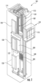
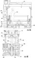
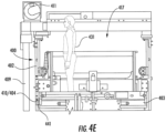
FIGS. 4A-4E , schematic illustrations of amechanic 431 on top of anelevator car 403 using anelevator overrun system 400 in accordance with an embodiment of the present invention are shown.FIG. 4A is a side elevation illustration with theelevator car 403 located at a maintenance maximum position (e.g.,second level 233 inFIGS. 2A-2C ) and theelevator overrun system 400 is in a deployed state.FIG. 4B is a front elevation illustration of the illustration ofFIG. 4A .FIG. 4C is a side elevation illustration with theelevator overrun system 400 is in a retracted state (prior to being moved upward).FIG. 4D is a front elevation illustration of the elevator car moved to a maximum elevator position (e.g.,third level 239 inFIGS. 2A-2C ) and theelevator overrun system 400 is in the retracted state.FIG. 4E is a side elevation illustration ofFIG. 4D . - As shown in
FIGS. 4A-4E , themechanic 431 is located on top of theelevator car 403 and may desire to perform maintenance on anelevator machine 411 of other elevator system component that is located at a top of anelevator shaft 417. Theelevator car 403 includes acar switch 441 that is configured to interact with a portion of theelevator overrun system 400 and prevent movement of theelevator car 403. Theelevator overrun system 400 is mounted to aguide rail 409 by mountingbrackets 406. - The
elevator overrun system 400 is similar to that shown and described above, including afirst body 402 and asecond body 404 that is moveable relative to thefirst body 402. Thefirst body 402 is fixedly positioned within an elevator shaft by the mountingbrackets 406. Thesecond body 404 includes alimit switch 410 that is similar in function and structure to that described above. Thelimit switch 410 is arranged to interact with thecar switch 441 to prevent movement of theelevator car 403 when the twoswitches - As shown in
FIGS. 4A-4B , theelevator overrun system 400 is in a deployed state, with thesecond body 404 secured to thefirst body 402 by a securingelement 408. Themechanic 431 can operate the securingelement 408 to unlock or release thesecond body 404 from thefirst body 402, to thus move thesecond body 404 relative to thefirst body 402 and into the retracted state, as shown inFIGS. 4C-4E . With theelevator overrun system 400 in the retracted state, thelimit switch 410 is no longer in contact or interaction with thecar switch 441, and thus theelevator car 403 can be moved upward into the maximum elevator position as shown inFIG. 4E . In this position, themechanic 431 can easily and safely perform maintenance on theelevator machine 411 or other components/elements of an elevator system that are located at the top of theelevator shaft 417. It will be appreciated that thelimit switch 410 can interact with thecar switch 441 in the position shown inFIGS. 4D-4E (e.g., top position). In this instance, a safety chain will be triggered by interaction of thelimit switch 410 and thecar switch 441 such that further upward motion of the elevator car cannot be achieved. - Turning now to
FIG. 5 , aflow process 500 for performing an overrun operation to enable maintenance at a top of an elevator shaft in accordance with an embodiment of the present invention is shown. The overrun operation can be performed using an elevator system as shown and described above, having an elevator car moveable along one or more guide rails within an elevator shaft, and an elevator overrun system located at a top of the elevator shaft. The overrun operation can be initiated by a mechanic or other person when it is desirable to perform maintenance at a top of an elevator shaft, such as to inspect or repair an elevator machine of the elevator system. - At
block 502, the elevator car is moved to the top landing within an elevator shaft, and thus a top of the elevator car can be positioned at a first level, e.g., a normal maximum position during normal operation of the elevator. The movement of the elevator car can be controlled by a control unit that is used to put the elevator system in a maintenance mode of operation and initiation of the overrun operation may be performed. In some configurations, block 502 can be omitted if the elevator car is already located at the top landing prior to initiation of theflow process 500. - At
block 504, the elevator system is placed into a maintenance mode of operation. In some embodiments, block 502 can be performed prior to block 504, or in other embodiments, block 502 and block 504 can be performed simultaneously. At the same time, or before or afterblock 502 and block 504, a mechanic may climb on top of the elevator car. - At
block 506, the elevator car is moved upward beyond the first level to a second level, the second level being a maximum maintenance position of the elevator car within the elevator shaft. The second level can be controlled by various safety features, including, but not limited to, a limit switch of the elevator overrun system in the deployed state and/or a safety chain, as will be appreciated by those of skill in the art. The elevator car may be driven slowly such that the upward motion of the elevator car is minimal and such that no damage may come to the elevator system and/or injury to a mechanic located on top of the elevator car. - At
block 508, the mechanic can operate the elevator overrun system to move a second body relative to a first body, and thus move a location of a limit switch, as shown and described above. That is, atblock 508, the elevator overrun system can be actuated or otherwise operated from the deployed state to a retracted state. - At
block 510, the elevator car can then be moved to a third level, which is a maximum elevator position within the elevator shaft. The third level can be defined by a car switch of the elevator car interactive with the moved limit switch of the elevator overrun system. Again, the elevator car may be driven slowly such that the upward motion of the elevator car is minimal and such that no damage may come to the elevator system and/or injury to a mechanic located on top of the elevator car. As described above, to enable the elevator car to be able to move to the third level, the counterweight is lowered into contact with counterweight buffer and compressing such buffer. Such contact and compression is enabled because the system described herein disables the safety change for the present operation. - At
block 512, the mechanic can perform a maintenance operation or task at the highest position within the elevator shaft in a safe manner. - Those of skill in the art will appreciate that the
flow process 500 can be reversed to bring the elevator car back to the first level, and then the elevator system can be returned to a normal mode of operation. Further, in some embodiments, certain steps may be omitted or additional steps may be added, without departing from the scope of the present invention. For example, in one non-limiting example, the second level can be omitted entirely, such that the elevator car is moved from the first level directly to the third level. - Those of skill in the art will appreciate that various example embodiments are shown and described herein, each having certain features in the particular embodiments, but the present invention is not thus limited. That is, features of the various embodiments can be exchanged, altered, or otherwise combined in different combinations without departing from the scope of the appended claims.
- Accordingly, the present invention is not to be seen as limited by the foregoing description, but is only limited by the scope of the appended claims.
Claims (13)
- An elevator overrun system (300, 400) comprising:a first body (302, 402) arranged to be fixedly mounted to a portion of an elevator system (101, 201) or elevator shaft (117, 217, 417);a second body (304, 404) positioned within the first body (302, 402) and moveable from a deployed state to a retracted state relative to the first body (302, 402);a lower contact (314) mounted to the first body (302, 402) at a first location;an upper contact (316) mounted to the first body (302, 402) at a second location;characterized in thatthe elevator overrun system further comprises:a limit switch (310, 410) located at a distal end (312) of the second body (304, 404), the limit switch (310, 410) configured to interact with a component of the elevator system (101, 201) to prevent movement of an elevator car (103, 203, 403); anda second body contact (318) mounted to the second body (304, 404);when the second body contact (318) is in contact with the lower contact (314), the deployed state is indicated, and, when the second body contact (318) is in contact with the upper contact (316), the retracted state is indicated.
- The elevator overrun system of claim 1, further comprising at least one mounting bracket (306, 406) fixedly connected to the first body (302, 402), the at least one mounting bracket (306, 406) arranged to mount the first body (302, 402) within the elevator shaft (117, 217, 417).
- The elevator overrun system (300, 400) of any preceding claim, further comprising a securing element (308, 408) arranged to secure the second body (304, 404) to the first body (302, 402) in at least the deployed state.
- The elevator overrun system (300, 400) of claim 3, wherein the securing element (308, 408) is one of attached to the first body (302, 402) or attached to the second body (304, 404).
- An elevator system (101, 201) including the elevator overrun system (300, 400) of any preceding claim.
- The elevator system (101, 201) of claim 5, wherein the elevator system (101, 201) includes:an elevator shaft (117, 217, 417) having a pit and a top;a guide rail (109, 209, 409) extending from the pit to the top of the elevator shaft (117, 217, 417); andan elevator car (103, 203, 403) moveable along the guide rail (109, 209, 409),wherein the first body (302, 402) is fixedly mounted to the guide rail (109, 209, 409) by the at least one mounting bracket (306, 406) and the elevator overrun system (300, 400) is positioned at the top of the elevator shaft (117, 217, 417).
- The elevator system (101, 201) of claim 6, wherein the car switch (241, 441) is mounted to an exterior of the elevator car (103, 203, 403),
wherein, when the car switch (241, 441) interacts with the limit switch (310, 410), the elevator car (103, 203, 403) is prevented from moving along the guide rail (109, 209, 409). - The elevator system (101, 201) of any of claims 6-7, wherein the elevator car (103, 203, 403) is moveable to a first level (229) in a normal mode of operation, a second level (233) that is higher within the elevator shaft (117, 217, 417) than the first level (229) in a maintenance mode of operation, and a third level (239) that is higher within the elevator shaft (117, 217, 417) than the second level (233) in a maintenance mode of operation.
- The elevator system (101, 201) of claim 8, wherein the elevator car (103, 203, 403) is prevented from moving to the third level (239) when the elevator overrun system (300, 400) is in the deployed state.
- The elevator system (101, 201) of any of claims 6-9, further comprising a safety chain (235) arranged to prevent movement of the elevator car (103, 203, 403) within the elevator shaft (117, 217, 417) when the safety chain (235) is operated.
- The elevator system (101, 201) of any of claims 6-10, further comprising a counterweight buffer (237) located in the pit of the elevator shaft (117, 217, 417),
wherein when the elevator overrun system (300, 400) is in the retracted state the counterweight buffer (237) is compressed. - A method of operating an elevator system (101, 201) having an elevator overrun system (300, 400) according to claim 1, the method comprising:moving an elevator car (103, 203, 403) within the elevator shaft (117, 217, 417) to a first level (229);operating the elevator overrun system (300, 400) from the deployed state to the retracted state; andmoving the elevator car (103, 203, 403) to a third level (239) that is higher in the elevator shaft (117, 217, 417) than the first level (229).
- The method of claim 12, further comprising moving the elevator car (103, 203, 403) to a second level (233) located between the first level (229) and the third level (239) prior to operating the elevator overrun system (300, 400).
Priority Applications (4)
| Application Number | Priority Date | Filing Date | Title |
|---|---|---|---|
| EP17305541.9A EP3401260B1 (en) | 2017-05-12 | 2017-05-12 | Elevator overrun systems |
| US15/967,863 US11078043B2 (en) | 2017-05-12 | 2018-05-01 | Elevator overrun systems |
| KR1020180052960A KR102566855B1 (en) | 2017-05-12 | 2018-05-09 | Elevator overrun systems |
| CN201810450238.2A CN108861938B (en) | 2017-05-12 | 2018-05-11 | Elevator overrun system |
Applications Claiming Priority (1)
| Application Number | Priority Date | Filing Date | Title |
|---|---|---|---|
| EP17305541.9A EP3401260B1 (en) | 2017-05-12 | 2017-05-12 | Elevator overrun systems |
Publications (2)
| Publication Number | Publication Date |
|---|---|
| EP3401260A1 EP3401260A1 (en) | 2018-11-14 |
| EP3401260B1 true EP3401260B1 (en) | 2023-08-09 |
Family
ID=58765785
Family Applications (1)
| Application Number | Title | Priority Date | Filing Date |
|---|---|---|---|
| EP17305541.9A Active EP3401260B1 (en) | 2017-05-12 | 2017-05-12 | Elevator overrun systems |
Country Status (4)
| Country | Link |
|---|---|
| US (1) | US11078043B2 (en) |
| EP (1) | EP3401260B1 (en) |
| KR (1) | KR102566855B1 (en) |
| CN (1) | CN108861938B (en) |
Families Citing this family (6)
| Publication number | Priority date | Publication date | Assignee | Title |
|---|---|---|---|---|
| US10457522B2 (en) * | 2016-06-30 | 2019-10-29 | Otis Elevator Company | Limit switch system including first limit device and second limit device |
| WO2020127493A1 (en) * | 2018-12-19 | 2020-06-25 | Inventio Ag | Device for creating a temporary protective space |
| EP3686146B1 (en) * | 2019-01-25 | 2022-05-11 | Otis Elevator Company | Controlling movement of an elevator car |
| EP3760561B1 (en) * | 2019-07-05 | 2022-05-11 | Otis Elevator Company | Elevator assembly with counterweight blocking stop |
| CN111532920B (en) * | 2020-05-07 | 2022-07-19 | 永大电梯设备(中国)有限公司 | Protection system for elevator maintenance personnel and elevator |
| EP4286315A1 (en) | 2022-06-03 | 2023-12-06 | Otis Elevator Company | Elevator car with moving electrical box |
Family Cites Families (28)
| Publication number | Priority date | Publication date | Assignee | Title |
|---|---|---|---|---|
| US3351059A (en) * | 1964-06-02 | 1967-11-07 | Norman Lettvin | Single stable dose vaccinator |
| JPH05246647A (en) * | 1992-03-06 | 1993-09-24 | Hitachi Ltd | Shock absorber and elevator device using it |
| JP2002114462A (en) * | 2000-10-11 | 2002-04-16 | Mitsubishi Electric Building Techno Service Co Ltd | Maintenance and inspection time operation device of elevator |
| SE521817C2 (en) | 2000-11-02 | 2003-12-09 | Alimak Ab | Safety arrangements at the elevator |
| JP2002145545A (en) | 2000-11-09 | 2002-05-22 | Mitsubishi Electric Corp | End safety device of elevator and maintenance of elevator by using the safety device |
| FI112640B (en) | 2000-12-22 | 2003-12-31 | Kone Corp | Elevator safety device |
| US6481534B1 (en) | 2001-08-27 | 2002-11-19 | Otis Elevator Company | Apparatus for maintaining adequate overhead space for car top mechanics in elevator systems |
| JP4197515B2 (en) | 2002-09-13 | 2008-12-17 | 三菱電機株式会社 | Elevator car fixing device |
| NZ532767A (en) | 2003-05-21 | 2004-12-24 | Inventio Ag | Lift installation with a buffer for creating a zone of protection in a lift installation and a method of creating a zone of protection |
| CN100379669C (en) * | 2003-06-06 | 2008-04-09 | 三菱电机株式会社 | Elevator apparatus |
| WO2005026033A1 (en) | 2003-09-15 | 2005-03-24 | Otis Elevator Company | Elevator inspection safety devices |
| EP1773704B1 (en) | 2004-05-05 | 2010-03-31 | Otis Elevator Company | Safety device for operator protection in low-height shaft bottom end elevators and elevator equipped therewith |
| EP2070858B1 (en) | 2006-06-26 | 2014-10-15 | Otis Elevator Company | Retractable stop for maintaining overhead clearance above an elevator car |
| EP2035315B1 (en) | 2006-06-30 | 2012-09-05 | Otis Elevator Company | Elevator having a shallow pit and/or a low overhead |
| JPWO2008062500A1 (en) * | 2006-11-20 | 2010-03-04 | 三菱電機株式会社 | Elevator equipment |
| FI125141B (en) * | 2007-01-03 | 2015-06-15 | Kone Corp | Elevator safety device |
| ES2344621B1 (en) * | 2007-12-26 | 2011-06-24 | Orona S. Coop. | SECURITY DEVICE FOR LIFTING EQUIPMENT AND LIFTING DEVICE THAT INCLUDES SUCH SECURITY DEVICE. |
| FI121423B (en) | 2009-04-23 | 2010-11-15 | Kone Corp | Safety arrangement for a lift |
| JP2011068428A (en) | 2009-09-24 | 2011-04-07 | Toshiba Elevator Co Ltd | Elevator |
| US20130025975A1 (en) | 2010-04-12 | 2013-01-31 | Otis Elevator Company | Retractable Stop for Low Overhead Elevators |
| CN201667298U (en) | 2010-04-13 | 2010-12-08 | 重庆钢铁(集团)有限责任公司 | Limit switch base |
| CN202124385U (en) | 2011-06-28 | 2012-01-25 | 苏州新达电扶梯部件有限公司 | Support assembly of lift car position switch |
| EP2900582A4 (en) | 2012-09-25 | 2016-09-28 | Otis Elevator Co | Compensatory measure for low overhead or low pit elevator |
| FI125118B (en) * | 2013-01-07 | 2015-06-15 | Kone Corp | Elevator |
| EP3012217B8 (en) | 2014-10-21 | 2017-08-02 | KONE Corporation | Safety system for elevator |
| WO2017068232A1 (en) * | 2015-10-22 | 2017-04-27 | Kone Corporation | Elevator with a safety arrangement and method for creating a safe working space in the upper part of the elevator shaft |
| CN205764153U (en) | 2016-05-26 | 2016-12-07 | 河北钢铁股份有限公司邯郸分公司 | A kind of can the three-dimensional limited support adjusted |
| CN205990116U (en) | 2016-09-10 | 2017-03-01 | 海宁德成机械配件有限公司 | A kind of elevator with apparatus for examination and repair |
-
2017
- 2017-05-12 EP EP17305541.9A patent/EP3401260B1/en active Active
-
2018
- 2018-05-01 US US15/967,863 patent/US11078043B2/en active Active
- 2018-05-09 KR KR1020180052960A patent/KR102566855B1/en active IP Right Grant
- 2018-05-11 CN CN201810450238.2A patent/CN108861938B/en active Active
Also Published As
| Publication number | Publication date |
|---|---|
| KR20180124751A (en) | 2018-11-21 |
| KR102566855B1 (en) | 2023-08-16 |
| US11078043B2 (en) | 2021-08-03 |
| US20180327222A1 (en) | 2018-11-15 |
| CN108861938A (en) | 2018-11-23 |
| EP3401260A1 (en) | 2018-11-14 |
| CN108861938B (en) | 2021-06-01 |
Similar Documents
| Publication | Publication Date | Title |
|---|---|---|
| EP3401260B1 (en) | Elevator overrun systems | |
| JP4680262B2 (en) | Safety devices used in elevator systems | |
| JP5015246B2 (en) | Safety device for ensuring a minimum space at the top and bottom of the elevator to be inspected and an elevator equipped with such a safety device | |
| JP4994837B2 (en) | Elevator equipment | |
| JP4664370B2 (en) | Elevator car safety stop device | |
| FI125176B (en) | Elevator provided with a safety equipment arrangement | |
| US9809420B2 (en) | Compensatory measure for low overhead or low pit elevator | |
| JP2009542550A (en) | Elevator with shallow pits and / or low overhead | |
| JP5619273B2 (en) | Retractable stop for low overhead elevator | |
| WO2004083091A1 (en) | Elevator device, and emergency stop device for elevator | |
| EP3336032B1 (en) | Elevator safety system and method of operating an elevator system | |
| JP5778722B2 (en) | Elevator with shallow pits and / or low overhead | |
| EP3686146B1 (en) | Controlling movement of an elevator car | |
| CN110182672B (en) | Toe guard system of elevator car | |
| EP3328772A1 (en) | Safety block for elevator | |
| CN113800349A (en) | Limiting and preventing device for elevator system and limiting and preventing method for elevator system | |
| JP4292204B2 (en) | Elevator equipment | |
| KR101953817B1 (en) | Platform safety device including passenger and obstacle detection function | |
| JP4190947B2 (en) | Elevator equipment | |
| JP2010168185A (en) | Elevator device | |
| EP3599211A1 (en) | Elevator car apron | |
| JP4248678B2 (en) | Elevator equipment | |
| JP2019099149A (en) | Train platform safety device including passenger and obstacle detection function | |
| JP2011256001A (en) | Elevator device | |
| CN106429726B (en) | Machine-roomless lift |
Legal Events
| Date | Code | Title | Description |
|---|---|---|---|
| PUAI | Public reference made under article 153(3) epc to a published international application that has entered the european phase |
Free format text: ORIGINAL CODE: 0009012 |
|
| STAA | Information on the status of an ep patent application or granted ep patent |
Free format text: STATUS: THE APPLICATION HAS BEEN PUBLISHED |
|
| AK | Designated contracting states |
Kind code of ref document: A1 Designated state(s): AL AT BE BG CH CY CZ DE DK EE ES FI FR GB GR HR HU IE IS IT LI LT LU LV MC MK MT NL NO PL PT RO RS SE SI SK SM TR |
|
| AX | Request for extension of the european patent |
Extension state: BA ME |
|
| STAA | Information on the status of an ep patent application or granted ep patent |
Free format text: STATUS: REQUEST FOR EXAMINATION WAS MADE |
|
| 17P | Request for examination filed |
Effective date: 20190429 |
|
| RBV | Designated contracting states (corrected) |
Designated state(s): AL AT BE BG CH CY CZ DE DK EE ES FI FR GB GR HR HU IE IS IT LI LT LU LV MC MK MT NL NO PL PT RO RS SE SI SK SM TR |
|
| STAA | Information on the status of an ep patent application or granted ep patent |
Free format text: STATUS: EXAMINATION IS IN PROGRESS |
|
| STAA | Information on the status of an ep patent application or granted ep patent |
Free format text: STATUS: EXAMINATION IS IN PROGRESS |
|
| 17Q | First examination report despatched |
Effective date: 20201020 |
|
| STAA | Information on the status of an ep patent application or granted ep patent |
Free format text: STATUS: EXAMINATION IS IN PROGRESS |
|
| GRAP | Despatch of communication of intention to grant a patent |
Free format text: ORIGINAL CODE: EPIDOSNIGR1 |
|
| STAA | Information on the status of an ep patent application or granted ep patent |
Free format text: STATUS: GRANT OF PATENT IS INTENDED |
|
| INTG | Intention to grant announced |
Effective date: 20230316 |
|
| GRAS | Grant fee paid |
Free format text: ORIGINAL CODE: EPIDOSNIGR3 |
|
| GRAA | (expected) grant |
Free format text: ORIGINAL CODE: 0009210 |
|
| STAA | Information on the status of an ep patent application or granted ep patent |
Free format text: STATUS: THE PATENT HAS BEEN GRANTED |
|
| AK | Designated contracting states |
Kind code of ref document: B1 Designated state(s): AL AT BE BG CH CY CZ DE DK EE ES FI FR GB GR HR HU IE IS IT LI LT LU LV MC MK MT NL NO PL PT RO RS SE SI SK SM TR |
|
| REG | Reference to a national code |
Ref country code: GB Ref legal event code: FG4D |
|
| REG | Reference to a national code |
Ref country code: CH Ref legal event code: EP |
|
| REG | Reference to a national code |
Ref country code: DE Ref legal event code: R096 Ref document number: 602017072404 Country of ref document: DE |
|
| REG | Reference to a national code |
Ref country code: IE Ref legal event code: FG4D |
|
| REG | Reference to a national code |
Ref country code: LT Ref legal event code: MG9D |
|
| REG | Reference to a national code |
Ref country code: NL Ref legal event code: MP Effective date: 20230809 |
|
| REG | Reference to a national code |
Ref country code: AT Ref legal event code: MK05 Ref document number: 1597333 Country of ref document: AT Kind code of ref document: T Effective date: 20230809 |
|
| PG25 | Lapsed in a contracting state [announced via postgrant information from national office to epo] |
Ref country code: GR Free format text: LAPSE BECAUSE OF FAILURE TO SUBMIT A TRANSLATION OF THE DESCRIPTION OR TO PAY THE FEE WITHIN THE PRESCRIBED TIME-LIMIT Effective date: 20231110 |
|
| PG25 | Lapsed in a contracting state [announced via postgrant information from national office to epo] |
Ref country code: IS Free format text: LAPSE BECAUSE OF FAILURE TO SUBMIT A TRANSLATION OF THE DESCRIPTION OR TO PAY THE FEE WITHIN THE PRESCRIBED TIME-LIMIT Effective date: 20231209 |
|
| PG25 | Lapsed in a contracting state [announced via postgrant information from national office to epo] |
Ref country code: SE Free format text: LAPSE BECAUSE OF FAILURE TO SUBMIT A TRANSLATION OF THE DESCRIPTION OR TO PAY THE FEE WITHIN THE PRESCRIBED TIME-LIMIT Effective date: 20230809 Ref country code: RS Free format text: LAPSE BECAUSE OF FAILURE TO SUBMIT A TRANSLATION OF THE DESCRIPTION OR TO PAY THE FEE WITHIN THE PRESCRIBED TIME-LIMIT Effective date: 20230809 Ref country code: PT Free format text: LAPSE BECAUSE OF FAILURE TO SUBMIT A TRANSLATION OF THE DESCRIPTION OR TO PAY THE FEE WITHIN THE PRESCRIBED TIME-LIMIT Effective date: 20231211 Ref country code: NO Free format text: LAPSE BECAUSE OF FAILURE TO SUBMIT A TRANSLATION OF THE DESCRIPTION OR TO PAY THE FEE WITHIN THE PRESCRIBED TIME-LIMIT Effective date: 20231109 Ref country code: NL Free format text: LAPSE BECAUSE OF FAILURE TO SUBMIT A TRANSLATION OF THE DESCRIPTION OR TO PAY THE FEE WITHIN THE PRESCRIBED TIME-LIMIT Effective date: 20230809 Ref country code: LV Free format text: LAPSE BECAUSE OF FAILURE TO SUBMIT A TRANSLATION OF THE DESCRIPTION OR TO PAY THE FEE WITHIN THE PRESCRIBED TIME-LIMIT Effective date: 20230809 Ref country code: LT Free format text: LAPSE BECAUSE OF FAILURE TO SUBMIT A TRANSLATION OF THE DESCRIPTION OR TO PAY THE FEE WITHIN THE PRESCRIBED TIME-LIMIT Effective date: 20230809 Ref country code: IS Free format text: LAPSE BECAUSE OF FAILURE TO SUBMIT A TRANSLATION OF THE DESCRIPTION OR TO PAY THE FEE WITHIN THE PRESCRIBED TIME-LIMIT Effective date: 20231209 Ref country code: HR Free format text: LAPSE BECAUSE OF FAILURE TO SUBMIT A TRANSLATION OF THE DESCRIPTION OR TO PAY THE FEE WITHIN THE PRESCRIBED TIME-LIMIT Effective date: 20230809 Ref country code: GR Free format text: LAPSE BECAUSE OF FAILURE TO SUBMIT A TRANSLATION OF THE DESCRIPTION OR TO PAY THE FEE WITHIN THE PRESCRIBED TIME-LIMIT Effective date: 20231110 Ref country code: FI Free format text: LAPSE BECAUSE OF FAILURE TO SUBMIT A TRANSLATION OF THE DESCRIPTION OR TO PAY THE FEE WITHIN THE PRESCRIBED TIME-LIMIT Effective date: 20230809 Ref country code: AT Free format text: LAPSE BECAUSE OF FAILURE TO SUBMIT A TRANSLATION OF THE DESCRIPTION OR TO PAY THE FEE WITHIN THE PRESCRIBED TIME-LIMIT Effective date: 20230809 |
|
| PG25 | Lapsed in a contracting state [announced via postgrant information from national office to epo] |
Ref country code: PL Free format text: LAPSE BECAUSE OF FAILURE TO SUBMIT A TRANSLATION OF THE DESCRIPTION OR TO PAY THE FEE WITHIN THE PRESCRIBED TIME-LIMIT Effective date: 20230809 |