EP2604565A1 - Lift system with upper limit of the maintenance area that can be raised - Google Patents
Lift system with upper limit of the maintenance area that can be raised Download PDFInfo
- Publication number
- EP2604565A1 EP2604565A1 EP11193516.9A EP11193516A EP2604565A1 EP 2604565 A1 EP2604565 A1 EP 2604565A1 EP 11193516 A EP11193516 A EP 11193516A EP 2604565 A1 EP2604565 A1 EP 2604565A1
- Authority
- EP
- European Patent Office
- Prior art keywords
- roof structure
- lifting mechanism
- area
- maintenance
- elevator installation
- Prior art date
- Legal status (The legal status is an assumption and is not a legal conclusion. Google has not performed a legal analysis and makes no representation as to the accuracy of the status listed.)
- Withdrawn
Links
Images


Classifications
-
- B—PERFORMING OPERATIONS; TRANSPORTING
- B66—HOISTING; LIFTING; HAULING
- B66B—ELEVATORS; ESCALATORS OR MOVING WALKWAYS
- B66B5/00—Applications of checking, fault-correcting, or safety devices in elevators
- B66B5/0043—Devices enhancing safety during maintenance
- B66B5/005—Safety of maintenance personnel
-
- B—PERFORMING OPERATIONS; TRANSPORTING
- B66—HOISTING; LIFTING; HAULING
- B66B—ELEVATORS; ESCALATORS OR MOVING WALKWAYS
- B66B11/00—Main component parts of lifts in, or associated with, buildings or other structures
- B66B11/0005—Constructional features of hoistways
-
- B—PERFORMING OPERATIONS; TRANSPORTING
- B66—HOISTING; LIFTING; HAULING
- B66B—ELEVATORS; ESCALATORS OR MOVING WALKWAYS
- B66B11/00—Main component parts of lifts in, or associated with, buildings or other structures
- B66B11/0035—Arrangement of driving gear, e.g. location or support
- B66B11/0045—Arrangement of driving gear, e.g. location or support in the hoistway
Definitions
- the invention relates to an elevator installation with a maintenance area, the upper limit of which is designed to be liftable according to the subject matter of the claims.
- a maintenance technician usually moves to the roof of the cabin and carries out the maintenance work on the drive unit or further components from there. For this maintenance can be carried out safely is to provide a minimal shelter between the roof of the cabin and the shaft end. This prevents possible crushing accidents in the event of a malfunction or incorrect manipulation of the elevator installation.
- the space provided for maintenance must be sufficiently large enough for the service technician to easily and quickly access the drive unit or other components to be serviced. The latter applies both to the design of the upper shaft area of a machine room-less elevator system as well as for the design of a separate engine room.
- such a machine room which is arranged above the shaft space, be provided in high-performance elevator systems in high-rise buildings.
- the object is achieved by an elevator system with a cab, a drive unit for
- Procedure of the cabin and a maintenance area in the upper area of the elevator system solved.
- the maintenance area is delimited against the top with a roof structure which is designed to be raised.
- Maintenance area here is to be understood as the area in which a service technician resides in order to service components, such as the drive unit.
- the roof structure covers the maintenance area and closes it against the top.
- the roof structure replaces a solid concrete or masonry shaft end used in a conventional elevator installation. During normal operation of the elevator system, this roof structure is in a lowered position on a part of the building structure, which encloses the maintenance room.
- the roof structure is raised. This creates a temporarily enlarged maintenance area. This has the advantage that the maintenance area during normal operation of the elevator system, in which there are no people on the roof of the cabin, can be kept small.
- the roof structure preferably has a base area which substantially corresponds to the base area of the maintenance area.
- the footprint of the maintenance area is limited by the lateral shaft walls or side walls of an engine room.
- the advantage here is the optimal accessibility of all components throughout the maintenance area.
- the elevator installation comprises a lifting mechanism for lifting the roof structure.
- the lifting mechanism is connected to a drive.
- the drive converts electrical, pneumatic or hydraulic drive energy by means of the lifting mechanism into a vertical lifting movement.
- the roof structure can be lifted quickly and effortlessly. This has an advantageous effect on the maintenance work of the service technician.
- the components to be serviced are quickly accessible and the maintenance technician can concentrate fully on the essential work steps of the maintenance.
- the drive of the lifting mechanism of a control unit of the elevator system controllable.
- a particular advantage of this configuration lies in the automatic raising of the roof structure when the elevator installation is put into a maintenance mode.
- the maintenance technician preferably sets the elevator installation into maintenance mode via a command input at a command input interface to the control unit.
- the control unit sends a control command to the drive of the lifting mechanism to raise the roof structure to the maintenance position.
- the elevator system can be brought back into the normal operating mode via a command input at the command input interface.
- the control unit preferably sends a control command to the drive of the lifting mechanism to lower the roof structure to the rest position again.
- the command input interface is preferably arranged outside the maintenance area, for example at a floor door, so that the roof structure is already raised before entering the maintenance area.
- the lifting mechanism can be prestressed with a spring arrangement against gravity.
- the spring arrangement thus enables a particularly power-saving operation of the lifting mechanism.
- the drive of the lifting mechanism can be made smaller.
- the lifting mechanism is easily manually operated in this embodiment, with a drive can also be omitted.
- the manual operation of the lifting mechanism in the maintenance area or in an area above the roof structure is made. The latter operating position is preferably on the roof of the building.
- a side wall is arranged laterally on the underside of the roof structure, which expands downwards.
- the vertical extent of the side wall corresponds at least to the lifting height of the roof structure.
- the side wall prevents dirt, water or other unwanted objects from entering the maintenance area or machine room or shaft area after lifting the roof structure.
- the sidewall is made of tent fabric, tarpaulin fabric, plastic film, sheet metal or other suitable materials that are sufficiently dense and stable to protect the maintenance area from environmental influences. and at the same time not unnecessarily increase the weight of the ceiling structure.
- the elevator system is designed without a machine room.
- the cabin and the drive unit are installed in a shaft space, the drive unit preferably in an upper area of the shaft space. Accordingly, the maintenance area is arranged in the upper region of the shaft space.
- the roof structure closes the shaft space from above.
- the roof structure is in lowered position largely at the same height as the roof of the building. This results in a particularly advantageous appearance of the roof of the building in the operating mode of the elevator system. Permanent projecting shaft end structures of the shaft space on the roof are thus avoidable.
- the cabin comprises a roof hatch, via which access to the maintenance area can be released.
- a first safety switch is connected to the roof hatch in such a way that, when the roof hatch is opened, the first safety switch opens and the elevator system stops. This ensures that a maintenance technician when entering the maintenance area between the car roof and the shaft end or the roof structure is not trapped by a faulty manipulation between the cabin and the shaft end.
- Another aspect relates to a second safety switch which is connected to the lifting mechanism.
- the second safety switch is configured so that when raising the roof structure of the first safety switch is reset and the elevator system can be brought into a maintenance mode.
- the advantage of the second safety switch is that the elevator installation can only be brought into a maintenance mode if the maintenance area is temporarily increased by the lifting of the roof structure. This ensures that the service technician can only carry out manipulations on the elevator installation if the planned safety-related and ergonomic measure is effective for protecting the health of the maintenance technician.
- the elevator installation is with a machine room fitted.
- the drive unit is installed in the machine room.
- the cabin is installed in the shaft as before.
- the machine room is arranged above the shaft space.
- the maintenance area is arranged in the engine room.
- the roof structure closes the engine room from above.
- the roof structure is preferably approximately at the same height as the roof of the building, thus allowing a favorable appearance of the roof of the building.
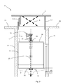
- the FIGS. 1 and 2 show a first machine room-less design variant of the elevator system 10.
- the elevator system 10 in this case has a cabin 11 which is movable in a shaft space 3 along guide rails 23.
- the elevator installation typically comprises a counterweight, carrying and propelling means 24, on which the cabin 11 and the counterweight are suspended, and a drive unit 12, which is in operative contact with the carrying and propelling means 24 via a traction sheave.
- the shaft space 3 is bounded laterally by shaft walls 21.
- the cabin 11 is suspended in a loop of the carrying and propellant means 24 on Kabinentragrollen 25.
- it is the person skilled in a suitable Suspension ratio which may also differ from the suspension ratio 2: 1, use.
- the counterweight in the FIGS. 1 and 2 not shown.
- the drive unit 12 is arranged in the upper region of the shaft space 3. Maintenance work on the drive unit 12 are performed in the upper region of the shaft space 3 between the car roof 26 and the upper shaft end.
- the shaft space 3 is bounded above by a roof structure 2.
- the Fig. 1 and 2 show the roof structure 2 in a raised position, so the maintenance position.
- the roof structure 2 In the lowered rest position of the roof structure 2, the roof structure 2 is located at the level of the roof 20 of the building on the building structure, preferably on the roof itself or on a shaft wall 21 on.
- the roof structure 2 is designed as a sheet metal or plastic plate or the like.
- a lifting mechanism 6 raises and lowers the roof structure 2.
- This lifting mechanism 6 is designed as a scissor mechanism as shown.
- the lifting mechanism 6 is connected to a drive which converts the drive energy into a vertical lifting or lowering movement of the lifting mechanism 6.
- These are, for example, electric motors, spindle drives and pneumatic or hydraulic drives.
- the lifting mechanism 6 is on the one hand indirectly or directly attached to the building structure, namely on the roof 20 or on the shaft walls 21, and on the other hand connected to the roof structure 2.
- the lifting mechanism 6 is prestressed with a spring arrangement against gravity.
- the spring arrangement is connected to the building structure and via a lever with at least one arm of the scissors mechanism, that the spring arrangement emits a stored elastic energy to the lifting mechanism 6 during a lifting movement.
- the spring arrangement absorbs the potential energy emitted by the roof structure 2 and the lifting mechanism 6. This allows the drive of the lifting mechanism 6 smaller dimensions.
- the lifting mechanism 6 could conveniently be manually raised or lowered in this spring-loaded configuration.
- the drive can be omitted here if necessary.
- the roof structure 2 is preferably connected to a side wall 5.1, 5.2, 5.3.
- the side wall 5.1, 5.2, 5.3 lies on the underside of the roof structure 2 and is connected in the edge region of the roof structure 2 with the same.
- the side wall 5.1, 5.2, 5.3 prevented in raised position of the roof structure 2, the penetration of particles or objects in the shaft space 3.
- the vertical extent of the side wall 5.1, 5.2, 5.3 is at least as high as the lifting height of the roof structure. 2
- Fig. 1 shows a first embodiment of the side wall 5.1, which is made of a flexible material such as tarpaulin material, tent fabric or the like.
- Fig. 2 however, two other rigid versions of the side wall 5.2, 5.3 are shown.
- the second embodiment is designed as a one-piece rigid sheet metal panel 5.2.
- the third embodiment relates to a side wall 5.3 with several telescopic sheet metal panels. Preferably, only one of the two last-mentioned embodiments is implemented simultaneously.
- plastic panels or the like can also be used as side walls.
- a one-piece molded shape of the roof structure 2 and the side wall 5.2 made of plastic material is particularly advantageous.
- a maintenance area 1 is provided which is arranged in the upper area of the shaft space 3.
- the maintenance area 1 is accessible via a roof hatch, which is arranged on the cabin roof 26.
- the roof hatch with a first safety switch can be monitored. When opening the roof hatch, the safety switch is opened. The opening of the first safety switch causes a shutdown of the elevator system 10th
- the lifting mechanism 6 is monitored by a second safety switch.
- the second safety switch is actuated.
- the first safety switch is reset and brought the elevator system 10 in a maintenance mode.
- the Figures 3 and 4 show a second embodiment variant of the elevator installation 10 with separate machine room 4.
- the elevator system 10 has a car 11.
- the cabin 11 is movable in a shaft space 3 along guide rails.
- the elevator system typically has a counterweight, a support and Propellant to which the car 11 and the counterweight are suspended and via a drive unit 22 which is in operative contact with the carrying and propellant via a traction sheave.
- the shaft space 3 is bounded by shaft walls 21.
- guide rails, counterweight and carrying and propellant in the FIGS. 1 and 2 not shown.
- the drive unit 22 is arranged here in a separate machine room 4.
- This engine room 4 essentially represents a maintenance area 7 in which the drive unit 22 is serviced.
- This maintenance area 7 is bounded laterally by machine room walls 27, at the bottom by a machine room floor 28 and at the top by a roof structure 2 and is arranged above the shaft space 3. Typically, the maintenance area 7 is accessible via an access door in a machine room wall 27.
- the roof structure 2 rests in a closed position on the building structure, preferably the roof of the building or the engine room walls 27.
- the roof structure 2 by means of a lifting mechanism 6 can be raised.
- the lifting mechanism 6 can be equipped with a previously described drive or a previously described spring arrangement.
- the roof structure 2 can be raised or lowered by means of the lifting mechanism 6 between a rest position and a maintenance position.
- the roof structure 2 and the side wall 5.1, 5.2, 5.3 from the first embodiment variant find their application in the second embodiment variant.
- the machine room wall 27 serves here next to the roof as a building structure for indirectly or directly attaching or supporting components of the lifting mechanism 6 or the roof structure 2.
Abstract
Description
Die Erfindung betrifft eine Aufzuganlage mit einem Wartungsbereich, dessen obere Begrenzung gemäss dem Gegenstand der Ansprüche anhebbar ausgestaltet ist.The invention relates to an elevator installation with a maintenance area, the upper limit of which is designed to be liftable according to the subject matter of the claims.
Ein wichtiger Punkt beim Bau eines Gebäudes ist die optimale Raumausnutzung. Dazu gehört auch eine platzsparende Gestaltung einer Aufzuganlage. Deshalb ist für eine geforderte Förderkapazität der Aufzuganlage der zugeteilte Schachtraum oder ein optionaler zusätzlicher Maschinenraum für die Antriebseinheit möglichst klein zu halten. Gleichzeitig ist genügend Raum zur Verfügung zu stellen, um beispielsweise die Antriebseinheit zu warten. Dabei sind sowohl sicherheitstechnische als auch ergonomische Aspekte zu berücksichtigen.An important point in the construction of a building is the optimal use of space. This also includes a space-saving design of an elevator system. Therefore, for a required conveying capacity of the elevator installation, the allocated shaft space or an optional additional machine space for the drive unit must be kept as small as possible. At the same time, sufficient space must be made available to service the drive unit, for example. Both safety and ergonomic aspects have to be considered.
Bei einer maschinenraumlosen Aufzuganlage, bei der die Antriebseinheit vorzugsweise im oberen Bereich des Schachtraums installiert ist, begibt sich ein Wartungstechniker üblicherweise auf das Dach der Kabine und führt von dort die Wartungsarbeiten an der Antriebseinheit oder weiteren Komponenten aus. Damit diese Wartungsarbeiten sicher ausgeführt werden können ist zwischen dem Dach der Kabine und dem Schachtende ein minimaler Schutzraum vorzusehen. Dies verhindert mögliche Quetschunfälle bei einer Fehlfunktion oder Fehlmanipulation der Aufzuganlage. Zudem muss der Raum, der für Wartungsarbeiten vorgesehen ist, genügend gross dimensioniert sein, dass der Wartungstechniker die Antriebseinheit oder andere zu wartende Komponenten einfach und schnell erreichen kann. Letzteres gilt sowohl für die Gestaltung des oberen Schachtbereiches einer maschinenraumlosen Aufzuganlage wie auch für die Gestaltung eines separaten Maschinenraums. Typischerweise kann ein solcher Maschinenraum, der oberhalb des Schachtraums angeordnet ist, bei Hochleistungs-Aufzuganlagen in Hochhäusern vorgesehen sein.In a machine room-less elevator installation in which the drive unit is preferably installed in the upper region of the shaft space, a maintenance technician usually moves to the roof of the cabin and carries out the maintenance work on the drive unit or further components from there. For this maintenance can be carried out safely is to provide a minimal shelter between the roof of the cabin and the shaft end. This prevents possible crushing accidents in the event of a malfunction or incorrect manipulation of the elevator installation. In addition, the space provided for maintenance must be sufficiently large enough for the service technician to easily and quickly access the drive unit or other components to be serviced. The latter applies both to the design of the upper shaft area of a machine room-less elevator system as well as for the design of a separate engine room. Typically, such a machine room, which is arranged above the shaft space, be provided in high-performance elevator systems in high-rise buildings.
Deshalb liegt der Erfindung die Aufgabe zugrunde den Schachtraum bzw. einen optionalen Maschinenraum möglichst raumsparend zu gestalten, insbesondere unter Berücksichtigung sicherheitstechnischer und ergonomischer Aspekte bei Wartungsarbeiten.It is therefore an object of the invention to make the shaft space or an optional engine room as space-saving as possible, in particular taking into account safety-related and ergonomic aspects during maintenance work.
Die Aufgabe wird durch eine Aufzuganlage mit einer Kabine, einer Antriebseinheit zumThe object is achieved by an elevator system with a cab, a drive unit for
Verfahren der Kabine und einem Wartungsbereich im oberen Bereich der Aufzuganlage gelöst. Dabei ist der Wartungsbereich gegen oben hin mit einer Dachstruktur abgegrenzt, die anhebbar ausgebildet ist.Procedure of the cabin and a maintenance area in the upper area of the elevator system solved. Here, the maintenance area is delimited against the top with a roof structure which is designed to be raised.
Unter Wartungsbereich ist hier der Bereich zu verstehen, in dem sich ein Wartungstechniker aufhält, um Komponenten, wie beispielswiese die Antriebseinheit, zu warten. Die Dachstruktur deckt den Wartungsbereich ab und schliesst diesen gegen oben hin ab. Die Dachstruktur ersetzt ein bei einer konventionellen Aufzuganlage verwendetes fest betoniertes oder gemauertes Schachtende. Im Normalbetrieb der Aufzuganlage liegt diese Dachstruktur in einer abgesenkten Position auf einem Teil der Gebäudestruktur auf, die den Wartungsraum umschliesst.Maintenance area here is to be understood as the area in which a service technician resides in order to service components, such as the drive unit. The roof structure covers the maintenance area and closes it against the top. The roof structure replaces a solid concrete or masonry shaft end used in a conventional elevator installation. During normal operation of the elevator system, this roof structure is in a lowered position on a part of the building structure, which encloses the maintenance room.
Für Wartungsarbeiten wird die Dachstruktur angehoben. Somit entsteht ein temporär vergrösserter Wartungsbereich. Dies hat den Vorteil, dass der Wartungsbereich im Normalbetrieb der Aufzuganlage, bei dem sich keine Personen auf dem Dach der Kabine aufhalten, klein gehalten werden kann.For maintenance work, the roof structure is raised. This creates a temporarily enlarged maintenance area. This has the advantage that the maintenance area during normal operation of the elevator system, in which there are no people on the roof of the cabin, can be kept small.
Vorzugsweise weist die Dachstruktur eine Grundfläche auf, die im Wesentlichen der Grundfläche des Wartungsbereichs entspricht. Die Grundfläche des Wartungsbereichs ist durch die seitliche Schachtwände oder seitliche Wände eines Maschinenraums begrenzt. Vorteilhaft ist dabei die optimale Zugänglichkeit aller Komponenten im gesamten Wartungsbereich.The roof structure preferably has a base area which substantially corresponds to the base area of the maintenance area. The footprint of the maintenance area is limited by the lateral shaft walls or side walls of an engine room. The advantage here is the optimal accessibility of all components throughout the maintenance area.
In einem weiteren Aspekt umfasst die Aufzuganlage einen Hubmechanismus zum Anheben der Dachstruktur. Vorzugsweise ist der Hubmechanismus mit einem Antrieb verbunden. Dabei setzt der Antrieb elektrische, pneumatische oder hydraulische Antriebsenergie mittels des Hubmechanismus in eine vertikale Hubbewegung um.In a further aspect, the elevator installation comprises a lifting mechanism for lifting the roof structure. Preferably, the lifting mechanism is connected to a drive. In this case, the drive converts electrical, pneumatic or hydraulic drive energy by means of the lifting mechanism into a vertical lifting movement.
Dank des Hubmechanismus ist die Dachstruktur schnell und mühelos hebbar. Dies wirkt sich vorteilhaft auf die Wartungsarbeit des Wartungstechnikers aus. Die zu wartenden Komponenten sind rasch zugänglich und der Wartungstechniker kann sich ganz auf die wesentlichen Arbeitsschritte der Wartung konzentrieren.Thanks to the lifting mechanism, the roof structure can be lifted quickly and effortlessly. This has an advantageous effect on the maintenance work of the service technician. The components to be serviced are quickly accessible and the maintenance technician can concentrate fully on the essential work steps of the maintenance.
Zudem ist der Antrieb des Hubmechanismus von einer Steuereinheit der Aufzuganlage ansteuerbar. Ein besonderer Vorteil dieser Konfiguration liegt in der automatischen Anhebung der Dachstruktur, wenn die Aufzuganlage in einen Wartungsmodus gesetzt wird. Vorzugsweise setzt der Wartungstechniker die Aufzuganlage über eine Befehlseingabe an einer Befehlseingabeschnittstelle zur Steuereinheit in den Wartungsmodus. Mit dem Wechsel in den Wartungsmodus sendet die Steuereinheit einen Steuerbefehl an den Antrieb des Hubmechanismus, die Dachstruktur in die Wartungsposition zu heben. Nach Beendigung der Wartungsarbeiten ist die Aufzuganlage wieder über eine Befehlseingabe an der Befehlseingabeschnittstelle in den normalen Betriebsmodus bringbar. Beim Wechsel in diesen Betriebsmodus sendet die Steuereinheit vorzugsweise einen Steuerbefehl an den Antrieb des Hubmechanismus, die Dachstruktur wieder in die Ruheposition abzusenken. Die Befehlseingabeschnittstelle ist vorzugsweise ausserhalb des Wartungsbereichs angeordnet, beispielsweise bei einer Stockwerktüre, damit die Dachstruktur bereits vor Betreten des Wartungsbereichs angehoben ist.In addition, the drive of the lifting mechanism of a control unit of the elevator system controllable. A particular advantage of this configuration lies in the automatic raising of the roof structure when the elevator installation is put into a maintenance mode. The maintenance technician preferably sets the elevator installation into maintenance mode via a command input at a command input interface to the control unit. With the change to the maintenance mode, the control unit sends a control command to the drive of the lifting mechanism to raise the roof structure to the maintenance position. After completion of the maintenance work, the elevator system can be brought back into the normal operating mode via a command input at the command input interface. When changing over to this operating mode, the control unit preferably sends a control command to the drive of the lifting mechanism to lower the roof structure to the rest position again. The command input interface is preferably arranged outside the maintenance area, for example at a floor door, so that the roof structure is already raised before entering the maintenance area.
Optional ist der Hubmechanismus mit einer Federanordnung gegen die Schwerkraft vorspannbar.Optionally, the lifting mechanism can be prestressed with a spring arrangement against gravity.
Die Federanordnung ermöglicht so eine besonders kräfteschonende Betätigung des Hubmechanismus. Dabei kann der Antrieb des Hubmechanismus kleiner dimensioniert werden. Zudem ist der Hubmechanismus in dieser Ausführung einfach manuell betätigbar, wobei ein Antrieb auch entfallen kann. Vorzugsweise wird die manuelle Betätigung des Hubmechanismus im Wartungsbereich oder in einem Bereich oberhalb der Dachstruktur vorgenommen. Letztere Betätigungsposition liegt vorzugsweise auf dem Dach des Gebäudes.The spring arrangement thus enables a particularly power-saving operation of the lifting mechanism. In this case, the drive of the lifting mechanism can be made smaller. In addition, the lifting mechanism is easily manually operated in this embodiment, with a drive can also be omitted. Preferably, the manual operation of the lifting mechanism in the maintenance area or in an area above the roof structure is made. The latter operating position is preferably on the roof of the building.
Gemäss eines weiteren Aspekts ist eine Seitenwand seitlich an der Unterseite der Dachstruktur angeordnet, die sich nach unten ausdehnt. Dabei entspricht die vertikale Ausdehnung der Seitenwand zumindest der Hubhöhe der Dachstruktur.According to a further aspect, a side wall is arranged laterally on the underside of the roof structure, which expands downwards. The vertical extent of the side wall corresponds at least to the lifting height of the roof structure.
Die Seitenwand verhindert, dass nach dem Anheben der Dachstruktur Schmutz, Wasser oder andere unerwünschte Gegenstände in den Wartungsbereich bzw. Maschinenraum oder Schachtraum eindringen können. Vorzugsweise ist die Seitenwand aus Zeltstoff, Planenstoff, Kunststoffolie, Blech oder anderen geeigneten Materialien gefertigt, die genügend dicht und stabil sind, um den Wartungsbereich vor Umwelteinflüssen zu schützen, und gleichzeitig das Gewicht der Deckenstruktur nicht unnötig erhöhen.The side wall prevents dirt, water or other unwanted objects from entering the maintenance area or machine room or shaft area after lifting the roof structure. Preferably, the sidewall is made of tent fabric, tarpaulin fabric, plastic film, sheet metal or other suitable materials that are sufficiently dense and stable to protect the maintenance area from environmental influences. and at the same time not unnecessarily increase the weight of the ceiling structure.
In einer ersten Ausgestaltungsvariante ist die Aufzuganlage maschinenraumlos ausgeführt. Dabei sind die Kabine und die Antriebseinheit in einem Schachtraum installiert, die Antriebseinheit vorzugsweise in einem oberen Bereich des Schachtraums. Dementsprechend ist der Wartungsbereich im oberen Bereich des Schachtraums angeordnet.In a first embodiment variant, the elevator system is designed without a machine room. In this case, the cabin and the drive unit are installed in a shaft space, the drive unit preferably in an upper area of the shaft space. Accordingly, the maintenance area is arranged in the upper region of the shaft space.
Bei dieser Ausgestaltungsvariante schliesst die Dachstruktur den Schachtraum gegen oben hin ab. Die Dachstruktur liegt dabei in abgesenkter Position weitgehend auf derselben Höhe wie das Dach des Gebäudes. Dies ergibt ein besonders vorteilhaftes Erscheinungsbild des Dachs des Gebäudes im Betriebsmodus der Aufzuganlage. Permanent überstehende Schachtendstrukturen des Schachtraums auf dem Dach sind so vermeidbar.In this embodiment variant, the roof structure closes the shaft space from above. The roof structure is in lowered position largely at the same height as the roof of the building. This results in a particularly advantageous appearance of the roof of the building in the operating mode of the elevator system. Permanent projecting shaft end structures of the shaft space on the roof are thus avoidable.
Gemäss eines weiteren Aspekts umfasst die Kabine eine Dachluke, über die ein Zutritt zum Wartungsbereich freigebbar ist. Vorzugsweise ist ein erster Sicherheitsschalter dermassen mit der Dachluke verbunden, dass beim Öffnen der Dachluke der erste Sicherheitsschalter öffnet und die Aufzuganlage stillegt. So ist sichergestellt, dass ein Wartungstechniker beim Betreten des Wartungsbereichs zwischen dem Kabinendach und dem Schachtende bzw. der Dachstruktur nicht durch eine Fehlmanipulation zwischen der Kabine und dem Schachtende eingeklemmt wird.According to a further aspect, the cabin comprises a roof hatch, via which access to the maintenance area can be released. Preferably, a first safety switch is connected to the roof hatch in such a way that, when the roof hatch is opened, the first safety switch opens and the elevator system stops. This ensures that a maintenance technician when entering the maintenance area between the car roof and the shaft end or the roof structure is not trapped by a faulty manipulation between the cabin and the shaft end.
Ein weiterer Aspekt betrifft einen zweiten Sicherheitsschalter, der mit dem Hubmechanismus verbunden ist. Der zweite Sicherheitsschalter ist dermassen konfiguriert, dass beim Anheben der Dachstruktur der erste Sicherheitsschalter wieder zurückgesetzt wird und die Aufzuganlage in einen Wartungsmodus bringbar ist.Another aspect relates to a second safety switch which is connected to the lifting mechanism. The second safety switch is configured so that when raising the roof structure of the first safety switch is reset and the elevator system can be brought into a maintenance mode.
Der Vorteil des zweiten Sicherheitsschalters liegt darin, dass die Aufzugsanlage erst dann in einen Wartungsmodus bringbar ist, wenn durch das Anheben der Dachstruktur der Wartungsbereich temporär vergrössert ist. So ist sichergestellt, dass der Wartungstechniker erst dann Manipulationen an der Aufzuganlage vornehmen kann, wenn die vorgesehene sicherheitstechnische und ergonomische Massnahme zum Schutz der Gesundheit des Wartungstechnikers wirksam ist.The advantage of the second safety switch is that the elevator installation can only be brought into a maintenance mode if the maintenance area is temporarily increased by the lifting of the roof structure. This ensures that the service technician can only carry out manipulations on the elevator installation if the planned safety-related and ergonomic measure is effective for protecting the health of the maintenance technician.
In einer zweiten Ausgestaltungsvariante ist die Aufzuganlage mit einem Maschinenraum ausgestattet. Im Maschinenraum ist die Antriebseinheit installiert. Die Kabine ist wie zuvor im Schachtraum installiert. Vorzugsweise ist der Maschinenraum oberhalb des Schachtraums angeordnet. Hierbei ist der Wartungsbereich im Maschinenraum angeordnet.In a second embodiment variant, the elevator installation is with a machine room fitted. The drive unit is installed in the machine room. The cabin is installed in the shaft as before. Preferably, the machine room is arranged above the shaft space. Here, the maintenance area is arranged in the engine room.
Bei dieser Ausgestaltungsvariante schliesst die Dachstruktur den Maschinenraum gegen oben hin ab. Auch hier liegt die Dachstruktur vorzugsweise in etwa auf derselben Höhe wie das Dach des Gebäudes und ermöglicht so ein vorteilhaftes Erscheinungsbild des Dachs des Gebäudes.In this embodiment variant, the roof structure closes the engine room from above. Again, the roof structure is preferably approximately at the same height as the roof of the building, thus allowing a favorable appearance of the roof of the building.
Im Folgenden wird die Erfindung durch Ausführungsbeispiele und anhand von Zeichnungen verdeutlicht und weiter beschrieben. Es zeigen:
-
Fig. 1 Eine erste Aufzuganlage in maschinenraumloser Ausführung mit einer hebbaren Dachstruktur mit flexiblen Seitenwänden; -
Fig. 2 Eine zweite Aufzuganlage in maschinenraumloser Ausführung mit einer hebbaren Dachstruktur mit starren Seitenwänden; -
Fig. 3 Eine dritte Ausführung einer Aufzuganlage mit Maschinenraum und mit einer hebbaren Dachstruktur mit flexiblen Seitenwänden; und -
Fig. 4 . Eine vierte Ausführung einer Aufzuganlage mit Maschinenraum und mit einer hebbaren Dachstruktur mit starren Seitenwänden.
-
Fig. 1 A first lift system in machine room-less design with a liftable roof structure with flexible side walls; -
Fig. 2 A second elevator system in a machine room-less design with a liftable roof structure with rigid side walls; -
Fig. 3 A third embodiment of an elevator installation with engine room and with a liftable roof structure with flexible side walls; and -
Fig. 4 , A fourth embodiment of an elevator installation with a machine room and with a liftable roof structure with rigid side walls.
Die
Die Antriebseinheit 12 ist im oberen Bereich des Schachtraums 3 angeordnet. Wartungsarbeiten an der Antriebseinheit 12 werden im oberen Bereich des Schachtraums 3 zwischen dem Kabinendach 26 und dem oberen Schachtende ausgeführt. Der Schachtraum 3 ist oben durch eine Dachstruktur 2 begrenzt. Die
Ein Hubmechanismus 6 hebt und senkt die Dachstruktur 2. Dieser Hubmechanismus 6 ist wie gezeigt als Scherenmechanismus ausgelegt. Vorzugsweise ist der Hubmechanismus 6 mit einem Antrieb verbunden, der die Antriebsenergie in eine senkrechte Hub- oder Senkbewegung des Hubmechanismus 6 umsetzt. Dazu eignen sich beispielsweise Elektromotoren, Spindelantriebe sowie pneumatische oder hydraulische Antriebe. Der Hubmechanismus 6 ist einerseits mittelbar oder unmittelbar an der Gebäudestruktur, nämlich am Dach 20 oder an den Schachtwänden 21, befestigt und andererseits mit der Dachstruktur 2 verbunden.A
Vorzugsweise ist der Hubmechanismus 6 mit einer Federanordnung gegen die Schwerkraft vorspannbar. Beim Scherenmechanismus wird dazu die Federanordnung dermassen mit der Gebäudestruktur und über einen Hebel mit mindestens einem Arm des Scherenmechanismus verbunden, dass die Federanordnung bei einer Hubbewegung eine gespeicherte elastische Energie an den Hubmechanismus 6 abgibt. Bei einer Absenkung des Hubmechanismus 6 hingegen nimmt die Federanordnung die abgegebene potentielle Energie der Dachstruktur 2 und des Hubmechanismus 6 auf. Damit lässt sich der Antrieb des Hebemechanismus 6 kleiner Dimensionieren.Preferably, the
Alternativ könnte der Hubmechanismus 6 in dieser Konfiguration mit Federanordnung bequem von Hand gehoben oder abgesenkt werden. Auf den Antrieb kann hier gegebenenfalls verzichtet werden.Alternatively, the
Die Dachstruktur 2 ist vorzugsweise mit einer Seitenwand 5.1, 5.2, 5.3 verbunden. Die Seitenwand 5.1, 5.2, 5.3 liegt auf der Unterseite der Dachstruktur 2 und ist im Randbereich der Dachstruktur 2 mit derselben verbunden. Die Seitenwand 5.1, 5.2, 5.3 verhindert bei angehobener Position der Dachstruktur 2 das Eindringen von Partikeln oder Gegenständen in den Schachtraum 3. Die vertikale Ausdehnung der Seitenwand 5.1, 5.2, 5.3 ist mindestens so hoch wie die Hubhöhe der Dachstruktur 2.The
Für Wartungsarbeiten am Antrieb 12 ist ein Wartungsbereich 1 vorgesehen, der im oberen Bereich des Schachtraums 3 angeordnet ist. Der Wartungsbereich 1 ist über eine Dachluke, die am Kabinendach 26 angeordnet ist, erreichbar. Vorzugsweise ist die Dachluke mit einem ersten Sicherheitsschalter überwachbar. Beim Öffnen der Dachluke wird der Sicherheitsschalter geöffnet. Das Öffnen des ersten Sicherheitsschalters bewirkt eine Stillsetzung der Aufzuganlage 10.For maintenance work on the
Vorzugsweise wird der Hubmechanismus 6 von einem zweiten Sicherheitsschalter überwacht. Beim Heben der Dachstruktur 2 wird der zweite Sicherheitsschalter betätigt. Hierbei wird der erste Sicherheitsschalter zurückgesetzt und die Aufzuganlage 10 in einen Wartungsmodus gebracht.Preferably, the
Die
Die Antriebseinheit 22 ist hier in einem separaten Maschinenraum 4 angeordnet. Dieser Maschinenraum 4 stellt im Wesentlichen einen Wartungsbereich 7 dar, in dem die Antriebseinheit 22 gewartet wird.The
Dieser Wartungsbereich 7 ist seitlich von Maschinenraumwänden 27, unten von einem Maschinenraumboden 28 und gegen oben hin von einer Dachstruktur 2 begrenzt und ist oberhalb des Schachtraums 3 angeordnet. Typischerweise ist der Wartungsbereich 7 über eine Zugangstür in einer Maschinenraumwand 27 betretbar. Die Dachstruktur 2 ruht in einer geschlossenen Position auf der Gebäudestruktur, vorzugsweise dem Dach des Gebäudes oder den Maschinenraumwänden 27.This
Analog zur ersten Ausgestaltungsform der Aufzuganlage 10 gemäss einer der beiden
Die Dachstruktur 2 und die Seitenwand 5.1, 5.2, 5.3 aus der ersten Ausgestaltungvariante finden auch in der zweiten Ausgestaltungsvariante ihre Anwendung. Im Unterschied zur ersten Ausgestaltungsvariante dient hier die Maschinenraumwand 27 neben dem Dach als Gebäudestruktur zum mittelbaren oder unmittelbaren Befestigen oder Abstützen von Bestandteilen des Hubmechanismus 6 oder der Dachstruktur 2.The
Claims (12)
Priority Applications (1)
| Application Number | Priority Date | Filing Date | Title |
|---|---|---|---|
| EP11193516.9A EP2604565A1 (en) | 2011-12-14 | 2011-12-14 | Lift system with upper limit of the maintenance area that can be raised |
Applications Claiming Priority (1)
| Application Number | Priority Date | Filing Date | Title |
|---|---|---|---|
| EP11193516.9A EP2604565A1 (en) | 2011-12-14 | 2011-12-14 | Lift system with upper limit of the maintenance area that can be raised |
Publications (1)
| Publication Number | Publication Date |
|---|---|
| EP2604565A1 true EP2604565A1 (en) | 2013-06-19 |
Family
ID=45218531
Family Applications (1)
| Application Number | Title | Priority Date | Filing Date |
|---|---|---|---|
| EP11193516.9A Withdrawn EP2604565A1 (en) | 2011-12-14 | 2011-12-14 | Lift system with upper limit of the maintenance area that can be raised |
Country Status (1)
| Country | Link |
|---|---|
| EP (1) | EP2604565A1 (en) |
Cited By (2)
| Publication number | Priority date | Publication date | Assignee | Title |
|---|---|---|---|---|
| WO2018002132A1 (en) * | 2016-06-30 | 2018-01-04 | Inventio Ag | Elevator system in the form of a climbing elevator system, comprising a specifically formed protective roof |
| US10457522B2 (en) | 2016-06-30 | 2019-10-29 | Otis Elevator Company | Limit switch system including first limit device and second limit device |
Citations (1)
| Publication number | Priority date | Publication date | Assignee | Title |
|---|---|---|---|---|
| JP2008230765A (en) * | 2007-03-20 | 2008-10-02 | Mitsubishi Electric Corp | Elevator device |
-
2011
- 2011-12-14 EP EP11193516.9A patent/EP2604565A1/en not_active Withdrawn
Patent Citations (1)
| Publication number | Priority date | Publication date | Assignee | Title |
|---|---|---|---|---|
| JP2008230765A (en) * | 2007-03-20 | 2008-10-02 | Mitsubishi Electric Corp | Elevator device |
Non-Patent Citations (1)
| Title |
|---|
| DATABASE WPI Week 200868, Derwent World Patents Index; AN 2008-L62107 * |
Cited By (3)
| Publication number | Priority date | Publication date | Assignee | Title |
|---|---|---|---|---|
| WO2018002132A1 (en) * | 2016-06-30 | 2018-01-04 | Inventio Ag | Elevator system in the form of a climbing elevator system, comprising a specifically formed protective roof |
| US10457522B2 (en) | 2016-06-30 | 2019-10-29 | Otis Elevator Company | Limit switch system including first limit device and second limit device |
| US11299372B2 (en) | 2016-06-30 | 2022-04-12 | Inventio Ag | Climbing elevator system having a protective roof |
Similar Documents
| Publication | Publication Date | Title |
|---|---|---|
| EP1246770B1 (en) | Inspection opening in an elevator car | |
| EP2190770B1 (en) | Elevator car for reduced upper ends of elevator shafts | |
| DE60108591T2 (en) | Device for ensuring the safety rooms for a hoist | |
| EP1026116B1 (en) | Access to drive unit of an elevator without machine-room | |
| DE69926244T3 (en) | Shaft safety system for lift | |
| WO2012126620A1 (en) | Elevator comprising a car that is movable in the maintenance mode | |
| DE102009053249A1 (en) | elevator | |
| WO2014067846A1 (en) | Lift with maintenance opening in the cab floor | |
| KR20000022574A (en) | Swiching device of control board in elevator | |
| EP1052212B1 (en) | Device for carrying out work in an elevator shaft | |
| EP2604565A1 (en) | Lift system with upper limit of the maintenance area that can be raised | |
| EP1562849B1 (en) | Elevator control unit integrated into a door jamb | |
| DE102017004719A1 (en) | Device for a secured area in a hoistway | |
| DE202018004562U1 (en) | Device for limiting the travel of a car and / or a counterweight of an elevator system with a guide rail | |
| AT517871B1 (en) | car | |
| DE102005007475B3 (en) | Person e.g. handicapped person, elevator for use in building, has telescopic unit that is extensible from upper storey to underlying storey, and safety limit switches provided in platform, cover plate, cabine or door | |
| EP2050703B1 (en) | Lift assembly for people and/or loads with at least one lift cabin | |
| DE112014007275T5 (en) | LIFT DEVICE | |
| AT15711U1 (en) | car | |
| DE959758C (en) | Safety device for elevators with insufficient crossing height | |
| CH702838B1 (en) | Lift for use in building, has control unit accommodated in cover of lift cab behind adjustable part, moving lift from cab interior with closed cab in service mode, and hung on cable and removable from storage table to operate control unit | |
| DE19827497A1 (en) | Lift shaft arrangement | |
| WO2020127493A1 (en) | Device for creating a temporary protective space | |
| CH704628B1 (en) | Elevator is provided with elevator car that is moved to multiple access levels inside elevator shaft comprising shaft doors, where shaft door opening bottom level is permanently locked | |
| CH704976A2 (en) | Elevator is provided with elevator car that is moved to multiple access levels inside elevator shaft comprising shaft doors, where shaft door opening bottom level is permanently locked |
Legal Events
| Date | Code | Title | Description |
|---|---|---|---|
| PUAI | Public reference made under article 153(3) epc to a published international application that has entered the european phase |
Free format text: ORIGINAL CODE: 0009012 |
|
| AK | Designated contracting states |
Kind code of ref document: A1 Designated state(s): AL AT BE BG CH CY CZ DE DK EE ES FI FR GB GR HR HU IE IS IT LI LT LU LV MC MK MT NL NO PL PT RO RS SE SI SK SM TR |
|
| AX | Request for extension of the european patent |
Extension state: BA ME |
|
| STAA | Information on the status of an ep patent application or granted ep patent |
Free format text: STATUS: THE APPLICATION HAS BEEN WITHDRAWN |
|
| 18W | Application withdrawn |
Effective date: 20130624 |