EP3265779B1 - Method for optical detection of a movement in a biological sample with a spatial extent - Google Patents
Method for optical detection of a movement in a biological sample with a spatial extent Download PDFInfo
- Publication number
- EP3265779B1 EP3265779B1 EP16708082.9A EP16708082A EP3265779B1 EP 3265779 B1 EP3265779 B1 EP 3265779B1 EP 16708082 A EP16708082 A EP 16708082A EP 3265779 B1 EP3265779 B1 EP 3265779B1
- Authority
- EP
- European Patent Office
- Prior art keywords
- sample
- detector
- light
- beam source
- light beam
- Prior art date
- Legal status (The legal status is an assumption and is not a legal conclusion. Google has not performed a legal analysis and makes no representation as to the accuracy of the status listed.)
- Active
Links
- 230000033001 locomotion Effects 0.000 title claims description 50
- 238000000034 method Methods 0.000 title claims description 40
- 238000001514 detection method Methods 0.000 title claims description 36
- 230000003287 optical effect Effects 0.000 title claims description 30
- 239000012472 biological sample Substances 0.000 title claims description 23
- 239000000523 sample Substances 0.000 claims description 170
- 230000005855 radiation Effects 0.000 claims description 46
- 238000005259 measurement Methods 0.000 claims description 30
- 238000005286 illumination Methods 0.000 claims description 23
- 230000008859 change Effects 0.000 claims description 20
- 230000003993 interaction Effects 0.000 claims description 17
- 210000004027 cell Anatomy 0.000 claims description 13
- 238000003384 imaging method Methods 0.000 claims description 9
- 230000008602 contraction Effects 0.000 claims description 7
- 230000001427 coherent effect Effects 0.000 claims description 6
- 239000011159 matrix material Substances 0.000 claims description 6
- 238000000338 in vitro Methods 0.000 claims description 5
- 210000001519 tissue Anatomy 0.000 claims description 5
- 229920001222 biopolymer Polymers 0.000 claims description 4
- 210000000663 muscle cell Anatomy 0.000 claims description 4
- 230000000737 periodic effect Effects 0.000 claims description 4
- 230000002123 temporal effect Effects 0.000 claims 2
- 230000010287 polarization Effects 0.000 description 21
- 230000008901 benefit Effects 0.000 description 7
- 210000003205 muscle Anatomy 0.000 description 6
- 230000005540 biological transmission Effects 0.000 description 4
- 238000012544 monitoring process Methods 0.000 description 4
- 230000035945 sensitivity Effects 0.000 description 4
- FHVDTGUDJYJELY-UHFFFAOYSA-N 6-{[2-carboxy-4,5-dihydroxy-6-(phosphanyloxy)oxan-3-yl]oxy}-4,5-dihydroxy-3-phosphanyloxane-2-carboxylic acid Chemical compound O1C(C(O)=O)C(P)C(O)C(O)C1OC1C(C(O)=O)OC(OP)C(O)C1O FHVDTGUDJYJELY-UHFFFAOYSA-N 0.000 description 3
- 229940072056 alginate Drugs 0.000 description 3
- 235000010443 alginic acid Nutrition 0.000 description 3
- 229920000615 alginic acid Polymers 0.000 description 3
- 238000013461 design Methods 0.000 description 3
- 238000010191 image analysis Methods 0.000 description 3
- 244000005700 microbiome Species 0.000 description 3
- 238000012216 screening Methods 0.000 description 3
- 239000000126 substance Substances 0.000 description 3
- 238000013459 approach Methods 0.000 description 2
- 230000001419 dependent effect Effects 0.000 description 2
- 238000011156 evaluation Methods 0.000 description 2
- 210000004165 myocardium Anatomy 0.000 description 2
- 239000013307 optical fiber Substances 0.000 description 2
- 238000013334 tissue model Methods 0.000 description 2
- 230000000007 visual effect Effects 0.000 description 2
- 230000001464 adherent effect Effects 0.000 description 1
- XAGFODPZIPBFFR-UHFFFAOYSA-N aluminium Chemical compound [Al] XAGFODPZIPBFFR-UHFFFAOYSA-N 0.000 description 1
- 229910052782 aluminium Inorganic materials 0.000 description 1
- 238000004458 analytical method Methods 0.000 description 1
- 238000003556 assay Methods 0.000 description 1
- 239000011324 bead Substances 0.000 description 1
- 230000022900 cardiac muscle contraction Effects 0.000 description 1
- 238000004113 cell culture Methods 0.000 description 1
- 239000003795 chemical substances by application Substances 0.000 description 1
- 238000005352 clarification Methods 0.000 description 1
- 239000004020 conductor Substances 0.000 description 1
- 238000007796 conventional method Methods 0.000 description 1
- 238000011161 development Methods 0.000 description 1
- 238000006073 displacement reaction Methods 0.000 description 1
- 230000000694 effects Effects 0.000 description 1
- 230000005670 electromagnetic radiation Effects 0.000 description 1
- 210000001671 embryonic stem cell Anatomy 0.000 description 1
- 238000002474 experimental method Methods 0.000 description 1
- 239000000835 fiber Substances 0.000 description 1
- 238000001914 filtration Methods 0.000 description 1
- 230000017525 heat dissipation Effects 0.000 description 1
- 230000020169 heat generation Effects 0.000 description 1
- 238000013537 high throughput screening Methods 0.000 description 1
- 238000002847 impedance measurement Methods 0.000 description 1
- 238000009434 installation Methods 0.000 description 1
- 230000002452 interceptive effect Effects 0.000 description 1
- 238000011835 investigation Methods 0.000 description 1
- 230000001795 light effect Effects 0.000 description 1
- 238000000691 measurement method Methods 0.000 description 1
- 238000012986 modification Methods 0.000 description 1
- 230000004048 modification Effects 0.000 description 1
- 230000004118 muscle contraction Effects 0.000 description 1
- 230000002107 myocardial effect Effects 0.000 description 1
- 230000008569 process Effects 0.000 description 1
- 238000012545 processing Methods 0.000 description 1
- 238000009877 rendering Methods 0.000 description 1
- 238000011160 research Methods 0.000 description 1
- 238000007493 shaping process Methods 0.000 description 1
- 239000002356 single layer Substances 0.000 description 1
- 230000019100 sperm motility Effects 0.000 description 1
- 210000000130 stem cell Anatomy 0.000 description 1
- 230000009182 swimming Effects 0.000 description 1
- 238000012360 testing method Methods 0.000 description 1
- 231100000419 toxicity Toxicity 0.000 description 1
- 230000001988 toxicity Effects 0.000 description 1
- 231100000820 toxicity test Toxicity 0.000 description 1
- 231100000041 toxicology testing Toxicity 0.000 description 1
- 230000009466 transformation Effects 0.000 description 1
- 230000001960 triggered effect Effects 0.000 description 1
- 238000010865 video microscopy Methods 0.000 description 1
Images


Classifications
-
- G—PHYSICS
- G01—MEASURING; TESTING
- G01N—INVESTIGATING OR ANALYSING MATERIALS BY DETERMINING THEIR CHEMICAL OR PHYSICAL PROPERTIES
- G01N33/00—Investigating or analysing materials by specific methods not covered by groups G01N1/00 - G01N31/00
- G01N33/48—Biological material, e.g. blood, urine; Haemocytometers
- G01N33/50—Chemical analysis of biological material, e.g. blood, urine; Testing involving biospecific ligand binding methods; Immunological testing
- G01N33/5005—Chemical analysis of biological material, e.g. blood, urine; Testing involving biospecific ligand binding methods; Immunological testing involving human or animal cells
-
- G—PHYSICS
- G01—MEASURING; TESTING
- G01P—MEASURING LINEAR OR ANGULAR SPEED, ACCELERATION, DECELERATION, OR SHOCK; INDICATING PRESENCE, ABSENCE, OR DIRECTION, OF MOVEMENT
- G01P13/00—Indicating or recording presence, absence, or direction, of movement
-
- G—PHYSICS
- G01—MEASURING; TESTING
- G01N—INVESTIGATING OR ANALYSING MATERIALS BY DETERMINING THEIR CHEMICAL OR PHYSICAL PROPERTIES
- G01N21/00—Investigating or analysing materials by the use of optical means, i.e. using sub-millimetre waves, infrared, visible or ultraviolet light
- G01N21/17—Systems in which incident light is modified in accordance with the properties of the material investigated
- G01N21/21—Polarisation-affecting properties
-
- G—PHYSICS
- G01—MEASURING; TESTING
- G01N—INVESTIGATING OR ANALYSING MATERIALS BY DETERMINING THEIR CHEMICAL OR PHYSICAL PROPERTIES
- G01N21/00—Investigating or analysing materials by the use of optical means, i.e. using sub-millimetre waves, infrared, visible or ultraviolet light
- G01N21/17—Systems in which incident light is modified in accordance with the properties of the material investigated
- G01N21/47—Scattering, i.e. diffuse reflection
- G01N21/4788—Diffraction
-
- G—PHYSICS
- G01—MEASURING; TESTING
- G01N—INVESTIGATING OR ANALYSING MATERIALS BY DETERMINING THEIR CHEMICAL OR PHYSICAL PROPERTIES
- G01N21/00—Investigating or analysing materials by the use of optical means, i.e. using sub-millimetre waves, infrared, visible or ultraviolet light
- G01N21/17—Systems in which incident light is modified in accordance with the properties of the material investigated
- G01N21/47—Scattering, i.e. diffuse reflection
- G01N21/49—Scattering, i.e. diffuse reflection within a body or fluid
-
- G—PHYSICS
- G01—MEASURING; TESTING
- G01N—INVESTIGATING OR ANALYSING MATERIALS BY DETERMINING THEIR CHEMICAL OR PHYSICAL PROPERTIES
- G01N21/00—Investigating or analysing materials by the use of optical means, i.e. using sub-millimetre waves, infrared, visible or ultraviolet light
- G01N21/17—Systems in which incident light is modified in accordance with the properties of the material investigated
- G01N21/47—Scattering, i.e. diffuse reflection
- G01N21/4788—Diffraction
- G01N2021/479—Speckle
-
- G—PHYSICS
- G01—MEASURING; TESTING
- G01N—INVESTIGATING OR ANALYSING MATERIALS BY DETERMINING THEIR CHEMICAL OR PHYSICAL PROPERTIES
- G01N21/00—Investigating or analysing materials by the use of optical means, i.e. using sub-millimetre waves, infrared, visible or ultraviolet light
- G01N21/17—Systems in which incident light is modified in accordance with the properties of the material investigated
- G01N21/47—Scattering, i.e. diffuse reflection
- G01N2021/4792—Polarisation of scatter light
-
- G—PHYSICS
- G01—MEASURING; TESTING
- G01N—INVESTIGATING OR ANALYSING MATERIALS BY DETERMINING THEIR CHEMICAL OR PHYSICAL PROPERTIES
- G01N33/00—Investigating or analysing materials by specific methods not covered by groups G01N1/00 - G01N31/00
- G01N33/15—Medicinal preparations ; Physical properties thereof, e.g. dissolubility
Definitions
- the invention relates to a method for the optical in-vitro detection of a movement in a biological sample with spatial extension.
- pieces of tissue grown from embryonic stem cells which have differentiated into muscle tissue, are used in toxicity tests to test the harmfulness of a substance to be tested.
- measurement methods are required to detect a movement, e.g. B. a contraction to detect in such a three-dimensional biological sample in the form of a cell cluster.
- Typical diameters of such cell clusters are 100 to 400 ⁇ m, with diameters in the millimeter range also being possible.
- Non-optical methods such as impedance measurements only work when in contact with the sample. However, if the sample shape deviates from the plane (adherent monolayer) or is even three-dimensional, still floating freely in a medium, the aforementioned techniques are not applicable.
- Automated imaging methods have the disadvantage that e.g. B. at a depth of field of 10 microns and the above-mentioned typical size of the cell clusters of 100 to 400 microns 10 to 40 image planes of the sample would have to be measured. With a typical minimum measurement time of approximately 10 seconds to be able to detect a movement and the additional time required for repositioning or focusing, such methods are not suitable for quickly monitoring a large number of samples.
- a serial measurement of large numbers of samples is generally not indicated due to the relatively long observation period due to the time scales of the biological dynamics.
- Imaging methods are not suitable for a parallel measurement of a large number of such samples, since it is difficult to implement, for geometric and installation space reasons, to arrange an imaging optical device in each cavity of the multiwell plate.
- WO 2014/123156 A1 discloses the detection of motion in a sample of muscle cells by calculating the contrast of an imaged speckle pattern.
- JA COLE ET AL "Laser speckle spectroscopy-a new method for using small swimming organisms as biomonitors", BIOIMAGING, Vol. 4, No. 4, December 1996, pages 243-253 discloses a punctiform measurement of a speckle pattern with subsequent Fourier transformation (FFT) to analyze the movement of micro-organisms.
- FFT Fourier transformation
- the object of the invention is in particular to provide a robust, contact-free method for motion detection that does not require any complex image analysis. It is a further object of the invention to provide a method which is suitable for the parallel analysis of a large number of samples in a screening environment.
- the invention is based on the technical knowledge that optical methods are most suitable for contactless monitoring and that since the exact location of a possible movement in the sample is not known in advance, it is necessary to illuminate the entire sample. Since the sample generally has a considerable extension in depth, ie greater than the depth of focus of imaging optics, the interactions of the light with the sample must be measured cumulatively over its entire distance through the sample. Transmission methods are therefore unsuitable, since the non-interacting part of the light would be measured here and the expected variations would be accompanied by high background and noise rendering the technique insensitive.
- the approach described is therefore based on the detection of the scattered, polarized and/or according to the invention the diffraction radiation of the exposed sample, with a search being made for the fluctuations caused by the sample movement in that part of the light which, through interaction with the sample in its beam direction, their state of polarization and/or according to the invention their diffraction pattern has been changed.
- the term “light” is also used instead of the term “radiation”. Both terms are to be regarded as synonymous in the context of the present invention and include electromagnetic radiation in the visible, IR and UV range.
- a method for the optical in-vitro detection of a movement in a biological sample with a spatial extension is thus provided.
- the method according to the invention comprises providing a holder for the sample, a light beam source, an optical system and a detector.
- the optics are designed to illuminate the entire sample in the recording with radiation emanating from the light beam source and to illuminate at least part of the radiation from the light beam source, the diffraction pattern of which is changed at any point within the sample by interaction with the sample to direct a detection surface of the detector, so that the interactions of the radiation emitted by the light beam source with the sample are measured cumulatively over its entire distance through the sample.
- the detector is designed to generate a measurement signal as a function of the detected radiation, the time profile of which indicates a time profile of the intensity of the detected radiation and/or from which the time profile of the intensity of the detected radiation can be derived.
- the method according to the invention also includes illuminating the sample with radiation from the light beam source and detecting a movement in the biological sample as a function of a change in the measurement signal over time.
- a particular advantage of the approach according to the invention is that the sample dynamics can be derived directly from the measured variable of the method, since the fluctuations caused by a sample movement in that part of the light that was changed in the diffraction pattern by interaction with the sample directly as fluctuations in the measurement signal are visible. Complex processing of the measurement data, as is the case with imaging methods, can thus be dispensed with.
- the invention it is possible to detect movement in the sample if a change in the measurement signal exceeds a predetermined threshold value.
- a movement is detected if the change in the measurement signal over time has a periodicity.
- the method can be carried out using comparatively simple optical elements. Optics for focusing on individual image planes and for successive scanning of the sample volume are not necessary.
- the device for carrying out the method can therefore be designed to be inexpensive and structurally compact.
- the method is also suitable for the parallel monitoring of a large number of samples and can be used in a process-efficient manner in screening environments or in automated high-throughput methods, e.g. e.g. high-throughput screening methods.
- the detector has a single-channel design or the detector emits a single-channel measurement signal.
- the measurement signal preferably indicates only the radiation intensity incident on the detector surface per unit of time. A movement in the sample can thus be detected directly based on a change or fluctuation in the signal over time.
- the detector is a non-imaging detector or a detector with a non-spatially resolved measurement signal, e.g. B. a non-spatially resolving photodetector, such as a photodiode.
- a non-imaging detector or a detector with a non-spatially resolved measurement signal e.g. B. a non-spatially resolving photodetector, such as a photodiode.
- Such detectors are compact and inexpensive.
- a spatially expansive biological sample is defined as a three-dimensional biological sample, e.g. B. in the form of a three-dimensional cell and / or tissue culture or a cell cluster understood.
- the diameter of the biological sample can be at least 50 micrometers ( ⁇ m) in at least one spatial direction, more preferably at least 50 micrometers in all spatial directions and is often more than 100 ⁇ m in all spatial directions.
- the diameter of the sample is preferably in the range of 100 ⁇ m to 5 mm, more preferably in the range of 100 ⁇ m up to 1 mm.
- the biological sample is a sample of living cells, ie cells that have active dynamics, ie cells that can trigger movement.
- the detection of a movement in the biological sample should be understood in particular as a movement within the sample or a movement of a sample component of the biological sample. In other words, it should generally be possible to detect dynamic phenomena in or within biological samples with a spatial extent. In the case of cell cultures from muscle cells, such movements can be triggered, for example, by the contraction of individual muscle cells.
- the biological sample cannot be a sample of free-swimming microorganisms, for example sperm.
- the method can be used to detect the movement of the free-swimming microorganisms, for example in the case of sperm to determine sperm motility.
- the optics can include illumination optics arranged on the illumination side, by means of which the radiation from the light beam source is directed onto the entire sample in order to illuminate the sample completely and as uniformly as possible.
- the optics can also include detection optics, by means of which the light emitted by the sample, which is changed in its beam direction, its polarization state and/or its diffraction pattern by interaction with the sample, is directed onto a detection surface of the detector.
- This functional property of the optics can be achieved using one or more appropriately arranged and configured known optical structural elements and components, such as As filters, lenses, diaphragms, refractive elements, etc., can be realized, which is explained below with reference to further exemplary embodiments.
- An advantageous embodiment variant provides that the optics are designed and/or the detector is arranged relative to the illumination beam path and the sample in such a way that there are no beam paths in which radiation from the light beam source transmitted through the sample impinges on the detector and/or in which Light from the light source bypasses the sample and hits the detector.
- a movement in the sample is detected based on a change in the diffraction pattern.
- the light beam source generates coherent light.
- the optics is formed, for. B. by means of a spatial filter, an edge region of a diffraction pattern, which is generated by the sample diffracted light of the light beam source, on the detector. Movement within the sample produces a change in the diffraction pattern, according to the invention a speckle pattern. Investigations within the scope of the invention have shown that the change in the diffraction pattern at its center is difficult to measure since the relative change in the radiation intensity is small. In the edge area, however, the change can be reliably detected and can e.g. B. to a short-term change from a local diffraction maximum to a local diffraction minimum or vice versa in the diffraction pattern. In a diffraction pattern, each point in the pattern contains the diffraction information for the entire sample.
- the optics comprise a pinhole diaphragm, which is arranged between the sample and the detector in such a way that a hole in the pinhole diaphragm is arranged at the edge area of the diffraction pattern generated by the sample.
- a pinhole diaphragm is understood to mean a hole-shaped opening, preferably a small hole-shaped opening and preferably without a lens. Pinholes are used to locally collect light.
- the end faces of optical fibers have long been used for the same purpose, particularly in confocal microscopes.
- All observation angles in which no transmitted light is received should preferably be regarded as the edge area of the diffraction pattern.
- the diffraction pattern is caused by positive and negative interference of light waves that have been diffracted by objects, in this case the sample. Whether there is positive or negative interference depends on the size of the object, the wavelength of the light and the viewing angle. Light that passes through the sample without interacting, ie transmitted light, ballistic photons, has the observation angle 0° and strikes the center of the diffraction pattern.
- the diffraction pattern is outshined by the transmitted light and the S/B (S/B: signal-to-background, signal-background) ratio and the S/N (S/N: signal-to-noise, signal-to-noise) ratio fall drastically. All observation angles in which no transmitted light is received should therefore preferably be regarded as the edge region of the diffraction pattern. Since the entire sample is irradiated here and the illumination is not is collimated, the "reception area" of the transmitted radiation is larger than just one point.
- the pinhole diaphragm can also have a plurality of holes which are arranged relative to the diffraction pattern in such a way that they are located in an edge region of the diffraction pattern.
- the holes are to be arranged in such a way that the superimposition of the diffraction radiation that hits the detector through the holes increases the diffraction effect and does not worsen it.
- the optics can comprise an aperture arranged between the light beam source and the sample, which is designed in such a way that radiation from the light beam source exits through an aperture of the aperture not directly, i. H. bypassing the sample, hits the hole of the pinhole.
- the optics can be a refractive optical element arranged between the light beam source and the sample, i. H. a radiation-refracting element, e.g. a convex lens or a prism, which is designed in such a way that radiation deflected by the refractive element is not emitted directly, ie. H. bypassing the sample, hits the hole of the pinhole.
- a movement in the sample is detected on the basis of a fluctuation in polarized light caused by the movement.
- the optics comprises a first polarization filter and a second polarization filter have different polarization directions, the first polarization filter being arranged between the light beam source and the sample and the second polarizing filter being arranged between the sample and the detector. Movement in the sample leads to a change in the interaction of the polarized light with the sample and a change in polarization states, resulting in a fluctuation in the detector signal.
- the detector and the second polarizing filter can be arranged on the opposite side of the sample with respect to the light beam source, on the side of the sample or on the same side as the light beam source.
- a movement in the sample is detected on the basis of a fluctuation in the light scattered at the sample caused by the movement.
- the detector for detecting scattered light from the sample can be arranged on the same side of the sample (1) as the light beam source.
- the detector for detecting lateral scattered radiation of the sample can be arranged at an angle and/or to the side of the sample in relation to the direction of the illumination beam path.
- the detector for transmitted light detection of scattered light from the sample can be arranged in the transmitted light direction to the sample.
- the optics comprises an aperture arranged between the light beam source and the sample, which is designed to direct light beams in the illumination beam path, which are transmitted through the sample to the detector would hit to block.
- the optics can comprise a refractive optical element arranged between the light beam source and the sample, which is designed to change a direction of the illumination beam path such that light beams transmitted through the sample do not impinge on the detector.
- the optics have a bandpass filter which is arranged in front of the detector and is designed to suppress ambient light. As a result, the sensitivity of the detection can be further increased.
- the optics in particular the illumination optics, comprise an axicon.
- the use of an axicon offers the advantage of more homogeneous illumination of spatially "deep" samples compared to convex lenses, since the focus of an axicon extends along the optical axis - instead of just in one point.
- Another advantage of an axicon is the simple spatial filtering of the incident (unaffected) light, since it is refracted at a constant angle to the optical axis.
- the sample can be located on a carrier matrix.
- the receptacle for the sample can thus include a carrier matrix, preferably a biopolymer.
- the sample can also be in a hanging drop.
- the recording of the sample can thus include a hanging drop.
- the well for the sample can be a well of a multiwell plate (microtiter plate).
- the receptacle can be a cavity of a multiwell plate which is designed to form a hanging drop on the individual cavities (so-called hanging drop multiwell plate).
- hanging drop multiwell plates are available, for example, from Insphero AG, CH-8952 Schlieren under the name “GravityPLUS TM 3D Culture and Assay Platform”.
- the patent EP 2342317 B1 discloses such a panel.
- the method is particularly suitable for the parallel monitoring of a large number of samples, e.g. B. of samples to be examined in the context of automated high-throughput methods.
- the holder for the biological samples is preferably a multiwell plate which has a plurality of wells arranged in rows and columns for holding the samples.
- the detector is designed as a detector array, preferably as a photodiode array, with a grid spacing of the individual detectors corresponding to a grid spacing of the cavities of the multiwell plate.
- the light beam source is designed to illuminate the individual cavities.
- the light beam source for illuminating the samples in the cavities is designed as a laser diode array, with a grid spacing of the individual laser diodes corresponding to the grid spacing of the cavities of the multiwell plate.
- a laser diode array represents a space-saving and energy-efficient lighting source.
- the mount for the laser diode array can be made of a heat-conducting material, preferably aluminum.
- the optics according to this variant, a lens array, z. B. a microlens array include, each lens of the lens array is associated with one of the laser diodes and the lenses direct the light of the laser diodes into the cavities.
- the light beam source can be designed as a conventional light source (laser, arc lamp, etc.), with the light from the light beam source being coupled into the individual cavities containing the samples via a fiber optic bundle to illuminate the samples. Each optical fiber is assigned to a cavity. This offers the advantage that the light source can be operated at a sufficient distance from the sample in order to avoid excessive heat generation in the vicinity of the sample.
- a device for contact-free in vitro detection of motion in a biological sample with spatial extent comprises a receptacle for the biological sample, a light source, a detector and an optical system that is designed to illuminate the entire sample in the receptacle with radiation emanating from the light source and at least part of the radiation from the light source that is emitted at any Place within the sample was changed by an interaction with the sample in its beam direction, its polarization state and / or its diffraction pattern to lead to a detection surface of the detector.
- the detector is designed to generate a measurement signal as a function of the detected radiation, which indicates the time profile of the intensity of the detected radiation and/or from which the time profile of the intensity of the detected radiation can be derived.
- the device can also have an evaluation unit that is set up to detect a movement in the biological sample by displaying and/or evaluating a change over time in the detected radiation.
- figure 1 shows a highly schematized representation of a method not according to the invention and a device not according to the invention.
- a device 100 for the optical in-vitro detection of a movement in a biological sample 1 with spatial expansion is provided.
- the device 100 comprises a holder (not shown) for the three-dimensional sample 1, a light beam source 6, an optical system 7, 8 and a detector 2.
- the recording is not limited to a specific type of recordings, but can be appropriate depending on the application and the type of sample, e.g. B. as a support, support plate, as a vessel, as a cavity of a multiwell plate, or as a support matrix in the form of a biopolymer, z. B. alginate on which the sample is grown.
- sample e.g. B. as a support, support plate, as a vessel, as a cavity of a multiwell plate, or as a support matrix in the form of a biopolymer, z. B. alginate on which the sample is grown.
- the light source 6 can, but does not have to be a coherent light source, e.g. B. be a laser. Only the design variants that use a diffraction pattern of the sample for motion detection (cf. Figures 4A to 4C , 5A to 5C ) use coherent radiation.
- This functional property of the optics can be achieved using one or more appropriately arranged and designed known optical devices and components such. As filters, lenses, apertures, refractive elements, etc., can be realized.
- the optics 7, 8 comprise an illumination optics 7 arranged on the illumination side, by means of which the radiation 10 from the light beam source 6 is directed onto the entire sample 1 in order to illuminate the sample completely and as uniformly as possible.
- the illumination optics can comprise suitable optical elements or components for beam shaping, such as diaphragms, lenses and/or filters.
- suitable optical elements or components for beam shaping such as diaphragms, lenses and/or filters.
- the use of an axicon is particularly advantageous.
- the optics 7, 8 also include a detection optics 8, by means of which the light 11 emitted by the sample, ie light from the light beam source 6, which has been changed by interaction with the sample 1 in its beam direction, its polarization state and/or diffraction pattern, on a Detection surface 2a of the detector 2 is passed.
- a detection optics 8 by means of which the light 11 emitted by the sample, ie light from the light beam source 6, which has been changed by interaction with the sample 1 in its beam direction, its polarization state and/or diffraction pattern, on a Detection surface 2a of the detector 2 is passed.
- a detection optics 8 For example, a scattering process is shown at point P1, in which light 11 is scattered in the direction of detector 2 and is imaged onto detector 2 by means of detection optics 8. Since the entire sample 1 is uniformly illuminated, the interaction of the incident light 10 can take place at any point within the sample 1, so that the interactions of the light with the sample are measured cumulatively by the detector
- the detection optics 8 can also contain optical elements that ensure that light whose beam direction, polarization state and/or diffraction pattern has not been changed by interaction with the sample does not strike the detector 2 .
- the detection optics 8 have a bandpass filter placed in front of the detector input and which filters out or suppresses the room light but allows light with a wavelength of the light beam source 6 to pass. This presupposes that a monochromatic light source is used or that a corresponding filter is arranged at the output of the light source in order to illuminate the sample with only a specific wavelength of light.
- the detection optics 8 can use diaphragms, lenses etc. to block beam paths in which the radiation from the light beam source 6 transmitted through the sample 1 would impinge on the detector and/or in which light from the light beam source 6 would impinge on the detector 2 bypassing the sample.
- the detector can also be arranged in such a way that no transmitted light 12 impinges on its detector surface 2a, e.g. B. by lateral arrangement of the detector 2 relative to the illumination beam path 10, as in figure 1 illustrated.
- the detector 2 is designed to generate a measurement signal 9 as a function of the detected radiation 11 , the time profile of which indicates a time profile of an intensity of the detected radiation 11 .
- the detector signal 9 thus corresponds to a volume measurement (full-volume measurement) of the sample.
- the detector 2 is a non-imaging detector or a detector with a non-spatially resolved measurement signal, preferably single-channel, so that only one measurement variable 9 is generated, which corresponds to the fluctuation in the light intensity recorded by the detector per unit of time.
- the detector 2 is z. B. a conventional photodiode 2.
- the sample 1 is illuminated and the corresponding measurement signal 9 is evaluated.
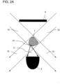
- the light beam source 6 is not shown in FIGS. 2A to 3C, but is located above the optics and detector arrangement shown, which can be seen from the beam path 10 .
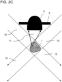
- FIGS 2A to 2E show non-inventive embodiments that use scattered light from the sample for motion detection.
- the detector 2 for transmitted light detection of scattered light 11 of the sample 2 is arranged in the transmitted light direction to the sample 1.
- a diaphragm 3 is arranged, which blocks light beams which would impinge on the detector 2 as beams transmitted through the sample 2 or which could impinge on the detector 2 laterally past the sample.
- the Illumination optics in the form of the diaphragm 3 therefore only allows radiation 12 transmitted through the sample that does not impinge on the detector 12 .
- a smaller aperture 3 which has a refractive optical element, e.g. B. a lens, an axicon, etc. is arranged downstream, which changes the direction of the illumination beam path 10 passed through the aperture 3 in such a way that the beams 12 transmitted through the sample 2 cannot impinge on the detector 2 .
- a refractive optical element e.g. B. a lens, an axicon, etc.
- the detector 2 for epidetection of scattered light in the form of reflection from the sample 1 is arranged on the same side of the sample 1 as the light beam source 6, with the detector surface 2a again facing the sample 2.
- This offers the advantage that no aperture is required to block transmitted light.
- a diaphragm surrounding the detector 2 is provided, which can reduce the influence of disruptive light influences.
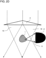
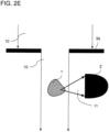
- FIG. 2D The peculiarity of the Figures 2D and 2E illustrated embodiment variants is that lateral scattered light 11 is detected.
- the detector 2 is arranged laterally to the direction of illumination.
- a refractive optical element e.g. B. a lens or prism 4, which changes the direction of the beam path so that light from the illumination beam path 10 cannot hit the detector 2 directly, ie bypassing the sample 1.
- the variant shown differs from the variant in Figure 2E in that instead of the refractive optical element 4 a diaphragm 3a is used, which has an opening for narrowing the beam path 10, so that again light of the illumination beam path 10 cannot hit the detector 2 directly, ie bypassing the sample 1.
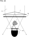
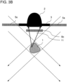
- the illumination optics comprise a first polarization filter 5a, which is arranged between the light beam source and the sample 1.
- the detection optics include a second polarization filter 5b, which has a different polarization direction compared to the first polarization filter 5a and is arranged between sample 1 and detector 2, preferably at the detector entrance.
- the detector 2 and the second polarization filter 5b can be arranged with respect to the light beam source on the opposite side of the sample 1, laterally from the sample 1 or on the same side as the light beam source, which is due to the different variants in the Figures 3A to 3C is shown.
- the polarization filter 5b Due to the different direction of polarization of the two polarization filters 5a and 5b, the polarization filter 5b only lets through light that has been "depolarized” by an interaction with the sample. The arrangement of the two polarization filters 5a and 5b thus ensures that no light transmitted through the sample or light that has bypassed the sample is detected.
- a movement in the sample changes the proportion of depolarized light and leads to a fluctuation in the detector signal, so that a movement in the sample 1 can in turn be recognized directly from the fluctuation in the detector signal.
- a refractive optical element 4 e.g. B. a convex lens or a prism, which focuses the illumination beam path 10 on the sample ( Figures 3A and 3C ).
- the detector 2 for epidetection of scattered light in the form of reflection from the sample 1 is arranged on the same side of the sample 1 as the light beam source 6.
- a screen 3 surrounding the detector 2 can be provided here, which can reduce the influence of disruptive light influences.
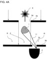
- the Figures 4A to 4C show embodiments of the invention that use a diffraction pattern of the sample in the form of a speckle pattern for motion detection.
- the light source 6 is a coherent light source, e.g. B. a laser diode.
- the light from the light beam source 6 diffracted at the sample produces a diffraction pattern with a center Z of high intensity and an edge region R of low intensity.
- the detection optics include a pinhole 3b arranged in front of the detector 2, which is arranged between the sample 1 and the detector 2 such that a hole 3c of the pinhole 3b is arranged in the edge region R of the diffraction pattern generated by the sample.
- the illumination optics includes an aperture 3a arranged between the light beam source and the sample, which is designed such that radiation from the light beam source 6 exiting through an aperture 3d of the aperture 3a does not strike the hole 3c of the pinhole 3b directly.
- Figures 4B and 4C includes the illumination optics arranged between the light beam source 6 and the sample 1 refractive optical element 4a, z. B. a convex lens, which is designed in such a way that radiation diffracted by the refractive optical element 4a does not hit the hole 3c of the pinhole diaphragm 3b directly, ie bypassing the sample.
- a bandpass filter 13 is arranged between the sample 1 and the pinhole 3b, which filters out room light that does not correspond to the wavelength of the light beam source 6.
- Figure 5A shows an example of a sample 1 in the form of a cell cluster.
- the cell cluster is in a hanging drop from which in Figure 5A only a portion formed in a well of a hanging drop multititer plate can be seen.
- the sample consists of a cardiac muscle tissue model differentiated from stem cells, which adheres to carrier beads 15 in the form of alginate.
- the sample shown has a diameter of approx. 1 millimeter.
- the sample 1 is completely illuminated with a laser diode with light of wavelength 650 nm.
- the on different Sample 1 which is structured on scales, diffracts the coherent light in a variety of ways and generates a complex diffraction pattern (so-called "speckle pattern") in the transmitted light direction.
- speckle pattern complex diffraction pattern
- Figure 5B 17a and 17b show two different states of a speckle pattern at minimum and maximum deflection of the contraction. Images 17a and 17b are for clarity only and are from a different experiment and do not show the speckle pattern of Sample 1 Figure 5A . However, the measuring principle is the same. Via a spatial filter, e.g. B. the pinhole 3b, a point in the edge region R of the diffraction pattern 17a, 17b on the detector 2 is imaged. The change in the pattern 17a, 17b now leads to a fluctuating amount of light that is let through by the pinhole 3b, and thus to a fluctuating detector signal 9, which in Figure 5C is shown. The periodic fluctuation of the signal 9 corresponds to the periodic contractions in muscle tissue. The representation in Figure 5C is only used for clarification, but again does not show a measurement signal that was measured when the sample shown in FIG. 1A was illuminated.
- a spatial filter e.g. B. the pinhole 3b
Description
Die Erfindung betrifft ein Verfahren zur optischen In-Vitro-Detektion einer Bewegung in einer biologischen Probe mit räumlicher Ausdehnung.The invention relates to a method for the optical in-vitro detection of a movement in a biological sample with spatial extension.
Aus der Praxis ist bekannt, dass ein Bedarf an einer Überwachung der aktiven Dynamik von geschlossenen und dreidimensionalen Zell- und Gewebekulturen in Bereichen wie der Entwicklungsbiologie, der Toxizitätstests und der pharmazeutischen Forschung besteht.It is known from practice that there is a need to monitor the active dynamics of closed and three-dimensional cell and tissue cultures in areas such as developmental biology, toxicity testing and pharmaceutical research.
Beispielsweise werden aus embryonalen Stammzellen gezüchtete Gewebestücke, die sich zu einem Muskelgewebe differenziert haben, im Rahmen von Toxizitätstests genutzt, um die Schädlichkeit von einer zu prüfenden Substanz zu prüfen. Hierbei wird untersucht, ob eine auf das Muskelgewebe aufgebrachte Substanz die Muskelkontraktionen des Muskelgewebes beeinflusst, was ein Indikator für die Toxizität der Substanz sein kann. Hierfür sind Messverfahren erforderlich, um eine Bewegung, z. B. eine Kontraktion, in einer solchen dreidimensionalen biologischen Probe in Form eines Zellhaufens zu detektieren. Typische Durchmesser solcher Zellhaufen betragen 100 bis 400 µm, wobei auch Durchmesser im Millimeterbereich möglich sind.For example, pieces of tissue grown from embryonic stem cells, which have differentiated into muscle tissue, are used in toxicity tests to test the harmfulness of a substance to be tested. This examines whether a substance applied to the muscle tissue affects the muscle contractions of the muscle tissue, which can be an indicator of the toxicity of the substance. For this purpose, measurement methods are required to detect a movement, e.g. B. a contraction to detect in such a three-dimensional biological sample in the form of a cell cluster. Typical diameters of such cell clusters are 100 to 400 μm, with diameters in the millimeter range also being possible.
Diese Studien werden derzeit in erster Linie durch visuelle Beobachtungen und selten durch Videomikroskopie mit anschließender Bildanalyse durchgeführt. Erstere sind zeitaufwändig und immer mit subjektiver Einschätzung verbunden. Letztere hat den Nachteil, dass komplexe abbildende Optiken und eine komplexe Bildanalyse verbunden mit einem erheblichen Rechenaufwand erforderlich sind. Nachteilig ist ferner ihre inhärente Empfindlichkeit gegenüber geringfügigen Verschiebungen.These studies are currently performed primarily by visual observations and rarely by video microscopy followed by image analysis. The former are time consuming and always associated with subjective assessment. The latter has the disadvantage that complex imaging optics and a complex image analysis combined with a considerable computing effort are required. Another disadvantage is their inherent sensitivity to small displacements.
Nichtoptische Methoden wie Impedanzmessungen funktionieren nur im Kontakt zur Probe. Wenn die Probeform jedoch von der Ebene (adhärente Monolage) abweicht oder gar dreidimensional ist, noch dazu frei in einem Medium schwimmt, sind die vorgenannten Techniken nicht anwendbar.Non-optical methods such as impedance measurements only work when in contact with the sample. However, if the sample shape deviates from the plane (adherent monolayer) or is even three-dimensional, still floating freely in a medium, the aforementioned techniques are not applicable.
Automatisierte bildgebende Verfahren haben den Nachteil, dass z. B. bei einer Schärfentiefe von 10 µm und der vorstehend genannten typischen Größe der Zellhaufen von 100 bis 400 µm 10 bis 40 Bildebenen der Probe durchgemessen werden müssten. Bei einer typischen Mindestmessdauer von ca. 10 Sekunden, um eine Bewegung detektieren zu können, und der zusätzlich für die Neupositionierung bzw. Fokussierung benötigten Zeit sind derartige Verfahren nicht geeignet, schnell eine Vielzahl von Proben zu überwachen.Automated imaging methods have the disadvantage that e.g. B. at a depth of field of 10 microns and the above-mentioned typical size of the cell clusters of 100 to 400
Eine serielle Messung von großen Probenzahlen ist auf Grund der durch die Zeitskalen der biologischen Dynamik recht langen Beobachtungsdauer generell nicht angezeigt. In der Praxis besteht jedoch der Bedarf, eine derartige Bewegungsdetektion an einer Vielzahl voneinander getrennter, z. B. in einer Multiwell-Platte, auch als Mikrotiterplatte bezeichnet, z. B. mit in 96 oder 384 Kavitäten (engl. Wells) gelagerten Proben, durchzuführen. Bildgebende Verfahren sind für eine parallele Messung einer Vielzahl solcher Proben nicht geeignet, da es aus geometrischen und bauraumtechnischen Gründen schwierig zu realisieren ist, an jeder Kavität der Multiwell-Platte eine bildgebende optische Vorrichtung anzuordnen.A serial measurement of large numbers of samples is generally not indicated due to the relatively long observation period due to the time scales of the biological dynamics. In practice, however, there is a need to carry out such a motion detection on a large number of separate, e.g. B. in a multiwell plate, also referred to as a microtiter plate, z. B. with samples stored in 96 or 384 wells. Imaging methods are not suitable for a parallel measurement of a large number of such samples, since it is difficult to implement, for geometric and installation space reasons, to arrange an imaging optical device in each cavity of the multiwell plate.
Das Dokument
Der Artikel:
Es ist somit eine Aufgabe der Erfindung, ein verbessertes Verfahren zur Detektion einer Bewegung in einer biologischen Probe mit räumlicher Ausdehnung bereitzustellen, mit dem Nachteile herkömmlicher Techniken vermieden werden können. Der Erfindung liegt insbesondere die Aufgabe zugrunde, ein robustes, kontaktfreies Verfahren zur Bewegungsdetektion bereitzustellen, das keine komplexe Bildanalyse erfordert. Es ist eine weitere Aufgabe der Erfindung, ein Verfahren bereitzustellen, das sich für die parallele Analyse einer Vielzahl von Proben in einer Screening-Umgebung eignet.It is therefore an object of the invention to provide an improved method for detecting a movement in a biological sample with a spatial extent, with which disadvantages of conventional techniques can be avoided. The object of the invention is in particular to provide a robust, contact-free method for motion detection that does not require any complex image analysis. It is a further object of the invention to provide a method which is suitable for the parallel analysis of a large number of samples in a screening environment.
Diese Aufgaben werden durch ein Verfahren mit den Merkmalen des unabhängigen Anspruchs 1 gelöst. Vorteilhafte Ausführungsformen und Anwendungen der Erfindung ergeben sich aus den abhängigen Ansprüchen und werden in der folgenden Beschreibung unter teilweiser Bezugnahme auf die Figuren näher erläutert.These objects are solved by a method having the features of
Die Erfindung beruht auf der technischen Erkenntnis, dass für eine kontaktlose Überwachung optische Methoden am geeignetsten sind und dass, da der genaue Ort einer möglichen Bewegung in der Probe nicht von vornherein bekannt ist, es erforderlich ist, die gesamte Probe zu beleuchten. Da die Probe in der Regel eine erhebliche Ausdehnung in der Tiefe, d. h. größer als die Schärfentiefe einer Abbildungsoptik, besitzt, müssen die Wechselwirkungen des Lichts mit der Probe auf seiner gesamten Strecke durch die Probe kumuliert gemessen werden. Transmissionsmethoden sind daher ungeeignet, da hier gerade der nicht-wechselwirkende Teil des Lichts gemessen würde und die zu erwartenden Schwankungen von einem hohen Hintergrund und Rauschen begleitet wären, der die Technik unempfindlich machen würde. Der beschriebene Ansatz beruht daher auf der Erfassung der Streu-, Polarisations- und/oder erfindungsgemäß der Beugungsstrahlung der belichteten Probe, wobei nach den durch die Probenbewegung hervorgerufenen Schwankungen in dem Teil des Lichts gesucht wird, der durch Wechselwirkung mit der Probe in ihrer Strahlrichtung, ihrem Polarisationszustand und/oder erfindungsgemäß ihrem Beugungsmuster verändert wurde. Dazu ist es vorteilhaft, das transmittierende Licht durch geeignete Filter von der Streu-, Polarisations- und/oder Beugungsstrahlung abzutrennen. Im Rahmen der vorliegenden Erfindung wird statt des Begriffs "Strahlung" auch der Begriff "Licht" verwendet. Beide Begriffe sind im Rahmen der vorliegenden Erfindung als gleichbedeutend anzusehen und umfassen elektromagnetische Strahlung im sichtbaren, IR- und UV-Bereich.The invention is based on the technical knowledge that optical methods are most suitable for contactless monitoring and that since the exact location of a possible movement in the sample is not known in advance, it is necessary to illuminate the entire sample. Since the sample generally has a considerable extension in depth, ie greater than the depth of focus of imaging optics, the interactions of the light with the sample must be measured cumulatively over its entire distance through the sample. Transmission methods are therefore unsuitable, since the non-interacting part of the light would be measured here and the expected variations would be accompanied by high background and noise rendering the technique insensitive. The approach described is therefore based on the detection of the scattered, polarized and/or according to the invention the diffraction radiation of the exposed sample, with a search being made for the fluctuations caused by the sample movement in that part of the light which, through interaction with the sample in its beam direction, their state of polarization and/or according to the invention their diffraction pattern has been changed. To this end, it is advantageous to separate the transmitted light from the scattered, polarized and/or diffracted radiation by means of suitable filters. In the context of the present invention, the term “light” is also used instead of the term “radiation”. Both terms are to be regarded as synonymous in the context of the present invention and include electromagnetic radiation in the visible, IR and UV range.
Gemäß allgemeinen Gesichtspunkten der Erfindung wird somit ein Verfahren zur optischen In-Vitro-Detektion einer Bewegung in einer biologischen Probe mit räumlicher Ausdehnung bereitgestellt.According to general aspects of the invention, a method for the optical in-vitro detection of a movement in a biological sample with a spatial extension is thus provided.
Das erfindungsgemäße Verfahren umfasst das Bereitstellen einer Aufnahme für die Probe, einer Lichtstrahlenquelle, einer Optik und eines Detektors. Hierbei ist die Optik ausgebildet, die ganze Probe in der Aufnahme mit von der Lichtstrahlenquelle ausgehender Strahlung zu beleuchten und zumindest einen Teil der Strahlung der Lichtstrahlenquelle, die an einer beliebigen Stelle innerhalb der Probe durch eine Wechselwirkung mit der Probe in ihrem Beugungsmuster verändert wird, auf eine Detektionsfläche des Detektors zu leiten, so dass die Wechselwirkungen der von der Lichtstrahlenquelle ausgesandten Strahlung mit der Probe auf seiner gesamten Strecke durch die Probe kumuliert gemessen werden. Der Detektor ist ausgebildet, in Abhängigkeit von der detektierten Strahlung ein Messsignal zu erzeugen, dessen zeitlicher Verlauf einen zeitlichen Verlauf der Intensität der detektierten Strahlung angibt und/oder aus dem der zeitliche Verlauf der Intensität der detektierten Strahlung ableitbar ist.The method according to the invention comprises providing a holder for the sample, a light beam source, an optical system and a detector. The optics are designed to illuminate the entire sample in the recording with radiation emanating from the light beam source and to illuminate at least part of the radiation from the light beam source, the diffraction pattern of which is changed at any point within the sample by interaction with the sample to direct a detection surface of the detector, so that the interactions of the radiation emitted by the light beam source with the sample are measured cumulatively over its entire distance through the sample. The detector is designed to generate a measurement signal as a function of the detected radiation, the time profile of which indicates a time profile of the intensity of the detected radiation and/or from which the time profile of the intensity of the detected radiation can be derived.
Das erfindungsgemäße Verfahren umfasst ferner das Beleuchten der Probe mit Strahlung der Lichtstrahlenquelle und das Detektieren einer Bewegung in der biologischen Probe in Abhängigkeit von einer zeitlichen Veränderung des Messsignals.The method according to the invention also includes illuminating the sample with radiation from the light beam source and detecting a movement in the biological sample as a function of a change in the measurement signal over time.
Ein besonderer Vorzug des erfindungsgemäßen Ansatzes ist, dass aus der Messgröße des Verfahrens direkt die Probendynamik ableitbar ist, da die von einer Probenbewegung hervorgerufenen Schwankungen in dem Teil des Lichts, der durch Wechselwirkung mit der Probe im Beugungsmuster verändert wurde, direkt als Schwankungen in dem Messsignal sichtbar sind. Somit kann auf eine aufwändige Verarbeitung der Messdaten, wie dies bei bildgebenden Verfahren der Fall ist, verzichtet werden.A particular advantage of the approach according to the invention is that the sample dynamics can be derived directly from the measured variable of the method, since the fluctuations caused by a sample movement in that part of the light that was changed in the diffraction pattern by interaction with the sample directly as fluctuations in the measurement signal are visible. Complex processing of the measurement data, as is the case with imaging methods, can thus be dispensed with.
Außerhalb der Erfindung ist es möglich, eine Bewegung in der Probe zu detektieren, falls eine Veränderung des Messsignals einen vorbestimmten Schwellenwert übersteigt. Erfindungsgemäß wird bei der Überprüfung von Kontraktionen in einem Muskelgewebe eine Bewegung detektiert, falls die zeitliche Veränderung des Messsignals eine Periodizität aufweist. Das Verfahren kann unter Verwendung vergleichsweise einfacher optischer Elemente durchgeführt werden. Eine Optik zur Fokussierung auf einzelne Bildebenen und zum sukzessiven Abtasten des Probenvolumens ist nicht notwendig. Daher kann die Vorrichtung zur Durchführung des Verfahrens kostengünstig und baulich kompakt ausgeführt sein.Outside of the invention, it is possible to detect movement in the sample if a change in the measurement signal exceeds a predetermined threshold value. According to the invention, when checking contractions in muscle tissue, a movement is detected if the change in the measurement signal over time has a periodicity. The method can be carried out using comparatively simple optical elements. Optics for focusing on individual image planes and for successive scanning of the sample volume are not necessary. The device for carrying out the method can therefore be designed to be inexpensive and structurally compact.
Aufgrund der einfachen Auswertung des Messsignals und des baulich kompakten Aufbaus ist das Verfahren auch für die parallele Überwachung einer Vielzahl von Proben geeignet und lässt sich prozesseffizient in Screening-Umgebungen bzw. in automatisierte Hochdurchsatzverfahren, z. B. High-Throughput Screening-Verfahren, integrieren.Due to the simple evaluation of the measurement signal and the structurally compact structure, the method is also suitable for the parallel monitoring of a large number of samples and can be used in a process-efficient manner in screening environments or in automated high-throughput methods, e.g. e.g. high-throughput screening methods.
Gemäß einer besonders bevorzugten Ausführungsvariante ist der Detektor einkanalig ausgeführt bzw. gibt der Detektor ein einkanaliges Messsignal aus. Das Messsignal gibt vorzugsweise nur die pro Zeiteinheit auf die Detektorfläche eintreffende Strahlungsintensität an. Eine Bewegung in der Probe kann somit direkt anhand einer zeitlichen Veränderung bzw. Schwankung des Signals detektiert werden.According to a particularly preferred embodiment variant, the detector has a single-channel design or the detector emits a single-channel measurement signal. The measurement signal preferably indicates only the radiation intensity incident on the detector surface per unit of time. A movement in the sample can thus be detected directly based on a change or fluctuation in the signal over time.
Der Detektor ist erfindungsgemäß ein nicht bildgebender Detektor oder ein Detektor mit nicht ortsaufgelöstem Messsignal, z. B. ein nicht ortsauflösender Photodetektor, beispielsweise eine Photodiode. Derartige Detektoren sind kompakt und kostengünstig.According to the invention, the detector is a non-imaging detector or a detector with a non-spatially resolved measurement signal, e.g. B. a non-spatially resolving photodetector, such as a photodiode. Such detectors are compact and inexpensive.
Unter einer biologischen Probe mit räumlicher Ausdehnung wird eine dreidimensionale biologische Probe, z. B. in Form einer dreidimensionalen Zell- und/oder Gewebekultur bzw. eines Zellhaufens, verstanden.A spatially expansive biological sample is defined as a three-dimensional biological sample, e.g. B. in the form of a three-dimensional cell and / or tissue culture or a cell cluster understood.
Der Durchmesser der biologischen Probe kann mindestens 50 Mikrometer (µm) in mindestens einer Raumrichtung, weiter vorzugsweise mindestens 50 Mikrometer in allen Raumrichtungen betragen und beträgt oft mehr als 100 µm in allen Raumrichtungen.The diameter of the biological sample can be at least 50 micrometers (μm) in at least one spatial direction, more preferably at least 50 micrometers in all spatial directions and is often more than 100 μm in all spatial directions.
Der Durchmesser der Probe liegt vorzugsweise im Bereich von 100 µm bis 5 mm, weiter vorzugsweise im Bereich von 100 µm bis 1 mm. Die biologische Probe ist eine Probe aus lebenden Zellen, d. h. aus Zellen, die eine Aktivdynamik aufweisen, d. h. Zellen, die eine Bewegung auslösen können.The diameter of the sample is preferably in the range of 100 μm to 5 mm, more preferably in the range of 100 μm up to 1 mm. The biological sample is a sample of living cells, ie cells that have active dynamics, ie cells that can trigger movement.
Unter der Detektion einer Bewegung in der biologischen Probe soll insbesondere eine Bewegung innerhalb der Probe oder eine Bewegung eines Probenbestandteils der biologischen Probe verstanden werden. Mit anderen Worten sollen allgemein dynamische Phänomene in bzw. innerhalb biologischer Proben mit räumlicher Ausdehnung detektiert werden können. Bei Zellkulturen aus Muskelzellen können derartige Bewegungen beispielsweise durch Kontraktion einzelner Muskelzellen ausgelöst werden.The detection of a movement in the biological sample should be understood in particular as a movement within the sample or a movement of a sample component of the biological sample. In other words, it should generally be possible to detect dynamic phenomena in or within biological samples with a spatial extent. In the case of cell cultures from muscle cells, such movements can be triggered, for example, by the contraction of individual muscle cells.
Bei der biologischen Probe kann es sich nicht erfindungsgemäß um eine Probe aus freischwimmenden Mikroorganismen, beispielsweise Spermien, handeln. In diesem Fall kann das Verfahren zur Detektion der Bewegung der freischwimmenden Mikroorganismen genutzt werden, beispielsweise im Falle von Spermien zur Bestimmung der Spermienmotilität.According to the invention, the biological sample cannot be a sample of free-swimming microorganisms, for example sperm. In this case, the method can be used to detect the movement of the free-swimming microorganisms, for example in the case of sperm to determine sperm motility.
Die Optik kann eine auf der Beleuchtungsseite angeordnete Beleuchtungsoptik umfassen, mittels der die Strahlung der Lichtstrahlenquelle auf die ganze Probe geleitet wird, um die Probe vollständig und möglichst gleichmäßig zu beleuchten. Die Optik kann ferner eine Detektionsoptik umfassen, mittels der das von der Probe ausgesandte Licht, das durch eine Wechselwirkung mit der Probe in ihrer Strahlrichtung, ihrem Polarisationszustand und/oder ihrem Beugungsmuster verändert wird, auf eine Detektionsfläche des Detektors geleitet wird. Diese funktionale Eigenschaft der Optik kann dabei unter Verwendung eines oder mehrerer zweckmäßig angeordneter und ausgestalteter bekannter optischer Bauelemente und Komponenten, wie z. B. Filter, Linsen, Blenden, refraktiver Elemente etc., realisiert werden, was nachfolgend anhand weiterer Ausführungsbeispiele erläutert wird.The optics can include illumination optics arranged on the illumination side, by means of which the radiation from the light beam source is directed onto the entire sample in order to illuminate the sample completely and as uniformly as possible. The optics can also include detection optics, by means of which the light emitted by the sample, which is changed in its beam direction, its polarization state and/or its diffraction pattern by interaction with the sample, is directed onto a detection surface of the detector. This functional property of the optics can be achieved using one or more appropriately arranged and configured known optical structural elements and components, such as As filters, lenses, diaphragms, refractive elements, etc., can be realized, which is explained below with reference to further exemplary embodiments.
Eine vorteilhafte Ausführungsvariante sieht hierbei vor, dass die Optik ausgebildet ist und/oder der Detektor relativ zum Beleuchtungsstrahlengang und der Probe so angeordnet ist, dass keine Strahlengänge existieren, bei denen durch die Probe transmittierte Strahlung der Lichtstrahlenquelle auf den Detektor trifft und/oder bei denen Licht der Lichtstrahlenquelle unter Umgehung der Probe auf den Detektor trifft.An advantageous embodiment variant provides that the optics are designed and/or the detector is arranged relative to the illumination beam path and the sample in such a way that there are no beam paths in which radiation from the light beam source transmitted through the sample impinges on the detector and/or in which Light from the light source bypasses the sample and hits the detector.
Gemäß dieser Ausführungsvariante trifft somit nur dasjenige Licht der Lichtstrahlenquelle auf den Detektor, das durch eine Wechselwirkung mit der Probe in seiner Strahlrichtung, seinem Polarisationszustand und/oder Beugungsmuster verändert wurde, während die Optik verhindert, dass Transmissionsstrahlung oder die Probe umgehende Strahlung die Detektionsfläche des Detektors trifft. Dadurch werden störende Hintergrundsignale reduziert und die Empfindlichkeit der Messung erhöht.According to this embodiment variant, only that light from the light beam source hits the detector that has been changed in its beam direction, polarization state and/or diffraction pattern by interaction with the sample, while the optics prevent transmission radiation or radiation bypassing the sample from the detection surface of the detector meets. This reduces interfering background signals and increases the sensitivity of the measurement.
Erfindungsgemäß wird eine Bewegung in der Probe anhand einer Veränderung des Beugungsmusters erkannt. Gemäß dieser Variante erzeugt die Lichtstrahlenquelle kohärentes Licht. Ferner ist die Optik ausgebildet, z. B. mittels eines Raumfilters, einen Randbereich eines Beugungsmusters, das von durch die Probe gebeugtem Licht der Lichtstrahlenquelle erzeugt wird, auf den Detektor abzubilden. Eine Bewegung innerhalb der Probe erzeugt eine Änderung des Beugungsmusters, erfindungsgemäß eines Speckle-Musters. Untersuchungen im Rahmen der Erfindung haben gezeigt, dass die Änderung des Beugungsmusters in seinem Zentrum schwierig zu messen ist, da die relative Änderung der Strahlungsintensität klein ist. Im Randbereich ist die Änderung jedoch zuverlässig zu erkennen und kann z. B. zu einer kurzzeitigen Änderung von einem lokalen Beugungsmaximum zu einem lokalen Beugungsminimum oder vice versa im Beugungsmuster führen. Bei einem Beugungsmuster enthält jeder Punkt des Musters die Beugungsinformation der gesamten Probe.According to the invention, a movement in the sample is detected based on a change in the diffraction pattern. According to this variant, the light beam source generates coherent light. Furthermore, the optics is formed, for. B. by means of a spatial filter, an edge region of a diffraction pattern, which is generated by the sample diffracted light of the light beam source, on the detector. Movement within the sample produces a change in the diffraction pattern, according to the invention a speckle pattern. Investigations within the scope of the invention have shown that the change in the diffraction pattern at its center is difficult to measure since the relative change in the radiation intensity is small. In the edge area, however, the change can be reliably detected and can e.g. B. to a short-term change from a local diffraction maximum to a local diffraction minimum or vice versa in the diffraction pattern. In a diffraction pattern, each point in the pattern contains the diffraction information for the entire sample.
Erfindungsgemäß umfasst die Optik eine Lochblende, die so zwischen der Probe und dem Detektor angeordnet ist, dass ein Loch der Lochblende an dem Randbereich des von der Probe erzeugten Beugungsmusters angeordnet ist.According to the invention, the optics comprise a pinhole diaphragm, which is arranged between the sample and the detector in such a way that a hole in the pinhole diaphragm is arranged at the edge area of the diffraction pattern generated by the sample.
Unter einer Lochblende wird eine lochförmige Öffnung, vorzugsweise eine kleine lochförmige Öffnung verstanden und vorzugsweise ohne Linse. Lochblenden dienen dem örtlich begrenzten Aufsammeln von Licht. Zum gleichen Zweck werden insbesondere in konfokalen Mikroskopen seit langer Zeit die Stirnseiten von optischen Fasern genutzt.A pinhole diaphragm is understood to mean a hole-shaped opening, preferably a small hole-shaped opening and preferably without a lens. Pinholes are used to locally collect light. The end faces of optical fibers have long been used for the same purpose, particularly in confocal microscopes.
Als Randbereich des Beugungsmusters sollen vorzugsweise alle Beobachtungswinkel gelten, in den kein transmittiertes Licht empfangen wird. Das Beugungsmuster wird durch positive und negative Interferenz von Lichtwellen, die an Objekten, hier der Probe, gebeugt wurden, hervorgerufen. Ob positiv oder negativ interferiert wird, hängt von Objektgröße, Wellenlänge des Lichts und Beobachtungswinkel ab. Licht, das die Probe ohne Wechselwirkung durchläuft, d. h. transmittiertes Licht, ballistische Photonen, hat den Beobachtungswinkel 0° und trifft in der Mitte des Beugungsmusters auf. Das Beugungsmuster wird durch das transmittierte Licht überstrahlt und das S/B (S/B: signal-to-background, Signal-Hintergrund)-Verhältnis und das S/N (S/N: signal-to-noise, Signal-Rausch)-Verhältnis fallen drastisch. Als Randbereich des Beugungsmusters sollen daher vorzugsweise alle Beobachtungswinkel gelten, in den kein transmittiertes Licht empfangen wird. Da hier die ganze Probe bestrahlt wird und die Beleuchtung nicht kollimiert erfolgt, ist der "Empfangsbereich" der transmittierten Strahlung größer als nur ein Punkt.All observation angles in which no transmitted light is received should preferably be regarded as the edge area of the diffraction pattern. The diffraction pattern is caused by positive and negative interference of light waves that have been diffracted by objects, in this case the sample. Whether there is positive or negative interference depends on the size of the object, the wavelength of the light and the viewing angle. Light that passes through the sample without interacting, ie transmitted light, ballistic photons, has the observation angle 0° and strikes the center of the diffraction pattern. The diffraction pattern is outshined by the transmitted light and the S/B (S/B: signal-to-background, signal-background) ratio and the S/N (S/N: signal-to-noise, signal-to-noise) ratio fall drastically. All observation angles in which no transmitted light is received should therefore preferably be regarded as the edge region of the diffraction pattern. Since the entire sample is irradiated here and the illumination is not is collimated, the "reception area" of the transmitted radiation is larger than just one point.
Gemäß einer weiteren Variante dieser Ausgestaltungsform kann die Lochblende auch mehrere Löcher aufweisen, die relativ zum Beugungsmuster so angeordnet sind, dass sie sich in einem Randbereich des Beugungsmusters befinden. Hierbei sind die Löcher so anzuordnen, dass die Überlagerung der Beugungsstrahlung, die durch die Löcher auf den Detektor trifft, den Beugungseffekt verstärkt und nicht verschlechtert.According to a further variant of this embodiment, the pinhole diaphragm can also have a plurality of holes which are arranged relative to the diffraction pattern in such a way that they are located in an edge region of the diffraction pattern. The holes are to be arranged in such a way that the superimposition of the diffraction radiation that hits the detector through the holes increases the diffraction effect and does not worsen it.
Gemäß einer weiteren Variante der Ausgestaltungsform, die eine Bewegung in der Probe anhand einer Veränderung des Beugungsmusters erkennt, kann die Optik eine zwischen der Lichtstrahlenquelle und der Probe angeordnete Blende umfassen, die so ausgeführt ist, dass eine durch eine Blendenöffnung der Blende austretende Strahlung der Lichtstrahlenquelle nicht direkt, d. h. unter Umgehung der Probe, auf das Loch der Lochblende trifft. Ferner kann die Optik ein zwischen der Lichtstrahlenquelle und der Probe angeordnetes refraktives optisches Element, d. h. ein die Strahlung brechendes Element, z. B. eine konvexe Linse oder ein Prisma, aufweisen, das so ausgeführt ist, dass durch das refraktive Element abgelenkte Strahlung nicht direkt, d. h. unter Umgehung der Probe, auf das Loch der Lochblende trifft. Diese Varianten stellen ein kostengünstiges und einfach zu justierendes Beispiel für eine Optik dar, die nur die gebeugte Strahlung zum Loch der Lochblende leitet.According to a further variant of the embodiment, which detects a movement in the sample based on a change in the diffraction pattern, the optics can comprise an aperture arranged between the light beam source and the sample, which is designed in such a way that radiation from the light beam source exits through an aperture of the aperture not directly, i. H. bypassing the sample, hits the hole of the pinhole. Furthermore, the optics can be a refractive optical element arranged between the light beam source and the sample, i. H. a radiation-refracting element, e.g. a convex lens or a prism, which is designed in such a way that radiation deflected by the refractive element is not emitted directly, ie. H. bypassing the sample, hits the hole of the pinhole. These variants represent a cost-effective and easy-to-adjust example of an optic that only directs the diffracted radiation to the hole in the pinhole.
Gemäß einer nicht erfindungsgemäßen Ausgestaltungsform wird eine Bewegung in der Probe anhand einer durch die Bewegung verursachten Schwankung von polarisiertem Licht erkannt. Gemäß dieser Ausgestaltungsform umfasst die Optik einen ersten Polarisationsfilter und einen zweiten Polarisationsfilter, die unterschiedliche Polarisationsrichtungen aufweisen, wobei der erste Polarisationsfilter zwischen Lichtstrahlenquelle und Probe und der zweite Polarisationsfilter zwischen Probe und Detektor angeordnet ist. Eine Bewegung in der Probe führt zu einer geänderten Wechselwirkung des polarisierten Lichts mit der Probe und zu einer Änderung der Polarisationszustände, was zu einer Schwankung im Detektorsignal führt.According to an embodiment not according to the invention, a movement in the sample is detected on the basis of a fluctuation in polarized light caused by the movement. According to this embodiment, the optics comprises a first polarization filter and a second polarization filter have different polarization directions, the first polarization filter being arranged between the light beam source and the sample and the second polarizing filter being arranged between the sample and the detector. Movement in the sample leads to a change in the interaction of the polarized light with the sample and a change in polarization states, resulting in a fluctuation in the detector signal.
Hierbei können der Detektor und der zweite Polarisationsfilter in Bezug auf die Lichtstrahlenquelle auf der gegenüberliegenden Seite der Probe, seitlich von der Probe oder auf der gleichen Seite wie die Lichtstrahlenquelle angeordnet sein.Here, the detector and the second polarizing filter can be arranged on the opposite side of the sample with respect to the light beam source, on the side of the sample or on the same side as the light beam source.
Gemäß einer weiteren nicht erfindungsgemäßen Ausgestaltungsform wird eine Bewegung in der Probe anhand einer durch die Bewegung verursachten Schwankung des an der Probe gestreuten Lichts erkannt. Hierbei kann der der Detektor zur Epidetektion von Streulicht der Probe auf der gleichen Seite der Probe (1) wie die Lichtstrahlenquelle angeordnet sein. Alternativ kann der der Detektor zur Detektion seitlicher Streustrahlung der Probe in Bezug auf die Richtung des Beleuchtungsstrahlengangs schräg und/oder seitlich von der Probe angeordnet sein.According to a further embodiment not according to the invention, a movement in the sample is detected on the basis of a fluctuation in the light scattered at the sample caused by the movement. In this case, the detector for detecting scattered light from the sample can be arranged on the same side of the sample (1) as the light beam source. Alternatively, the detector for detecting lateral scattered radiation of the sample can be arranged at an angle and/or to the side of the sample in relation to the direction of the illumination beam path.
Diese nicht erfindungsgemäßen Varianten bieten den Vorteil, dass keine optischen Komponenten wie z. B. Blenden notwendig sind, die verhindern, dass Transmissionsstrahlung auf den Detektor trifft.These non-inventive variants offer the advantage that no optical components such. B. screens are necessary to prevent transmission radiation hitting the detector.
Ferner kann der Detektor zur Durchlichtdetektion von Streulicht der Probe in Durchlichtrichtung zur Probe angeordnet sein. Gemäß dieser Variante umfasst die Optik eine zwischen der Lichtstrahlenquelle und der Probe angeordnete Blende, die ausgebildet ist, im Beleuchtungsstrahlengang Lichtstrahlen, die als durch die Probe transmittierte Strahlen auf den Detektor treffen würden, zu blockieren. Alternativ oder zusätzlich kann die Optik ein zwischen der Lichtstrahlenquelle und der Probe angeordnetes refraktives optisches Element umfassen, das ausgebildet ist, eine Richtung des Beleuchtungsstrahlengangs so zu verändern, dass durch die Probe transmittierte Lichtstrahlen nicht auf den Detektor treffen.Furthermore, the detector for transmitted light detection of scattered light from the sample can be arranged in the transmitted light direction to the sample. According to this variant, the optics comprises an aperture arranged between the light beam source and the sample, which is designed to direct light beams in the illumination beam path, which are transmitted through the sample to the detector would hit to block. Alternatively or additionally, the optics can comprise a refractive optical element arranged between the light beam source and the sample, which is designed to change a direction of the illumination beam path such that light beams transmitted through the sample do not impinge on the detector.
Ferner ist es vorteilhaft, wenn die Optik einen vor dem Detektor angeordneten Bandpassfilter aufweist, der zur Raumlichtunterdrückung ausgebildet ist. Dadurch kann die Empfindlichkeit der Detektion weiter erhöht werden.Furthermore, it is advantageous if the optics have a bandpass filter which is arranged in front of the detector and is designed to suppress ambient light. As a result, the sensitivity of the detection can be further increased.
Gemäß einer weiteren vorteilhaften Variante umfasst die Optik, insbesondere die Beleuchtungsoptik, ein Axicon. Die Verwendung eines Axicons bietet den Vorzug einer homogeneren Ausleuchtung räumlich "tiefer" Proben, verglichen mit konvexen Linsen, da sich der Fokus eines Axicons entlang der optischen Achse erstreckt - statt nur in einem Punkt. Ein weiterer Vorzug eines Axicons ist die einfache räumliche Filterung des eingestrahlten (nicht beeinflussten) Lichts, da dieses mit einem konstanten Winkel zur optischen Achse gebrochen wird.According to a further advantageous variant, the optics, in particular the illumination optics, comprise an axicon. The use of an axicon offers the advantage of more homogeneous illumination of spatially "deep" samples compared to convex lenses, since the focus of an axicon extends along the optical axis - instead of just in one point. Another advantage of an axicon is the simple spatial filtering of the incident (unaffected) light, since it is refracted at a constant angle to the optical axis.
Eine Möglichkeit der erfindungsgemäßen Realisierung sieht vor, dass sich die Probe auf einer Trägermatrix befinden kann. Die Aufnahme der Probe kann somit eine Trägermatrix, vorzugsweise ein Biopolymer, umfassen. Die Probe kann sich ferner in einem hängendem Tropfen befinden. Die Aufnahme der Probe kann somit einen hängenden Tropfen umfasst. Ferner kann die Aufnahme der Probe als eine sich in einem hängenden Tropfen befindliche Trägermatrix, vorzugsweise ein Biopolymer wie z. B. Alginat, ausgeführt sein.One possibility of realization according to the invention provides that the sample can be located on a carrier matrix. The receptacle for the sample can thus include a carrier matrix, preferably a biopolymer. The sample can also be in a hanging drop. The recording of the sample can thus include a hanging drop. Furthermore, the uptake of the sample as a support matrix located in a hanging drop, preferably a biopolymer such as e.g. B. alginate, be performed.
Für die Anwendung des Verfahrens in Screening-Umgebungen kann die Aufnahme für die Probe eine Kavität einer Multiwell-Platte (Mikrotiterplatte) sein. Weiterhin kann die Aufnahme eine Kavität einer Multiwell-Platte sein, die zur Ausbildung eines hängenden Tropfens an den einzelnen Kavitäten ausgebildet ist (sog. Hängender-Tropfen-Multiwell-Platte). Solche Hängender-Tropfen-Multiwell-Platten werden beispielsweise von der Firma InspheroAG, CH-8952 Schlieren unter der Bezeichnung "GravityPLUS™ 3D Culture and Assay Platform" angeboten. Auch die Patentschrift
Vorstehend wurde bereits erwähnt, dass sich das Verfahren besonders für die parallele Überwachung einer Vielzahl von Proben eignet, z. B. von Proben, die im Rahmen von automatisierten Hochdurchsatzverfahren untersucht werden sollen.It was already mentioned above that the method is particularly suitable for the parallel monitoring of a large number of samples, e.g. B. of samples to be examined in the context of automated high-throughput methods.
Eine vorteilhafte Weiterbildung des Verfahrens sieht daher vor, dass mit diesem eine parallele optische Detektion einer Bewegung in mehreren voneinander getrennten biologischen Proben durchgeführt wird. Hierbei ist die Aufnahme für die biologischen Proben vorzugsweise eine Multiwell-Platte, die eine Mehrzahl von in Reihen und Spalten angeordneten Kavitäten zur Aufnahme der Proben aufweist. Der Detektor ist als Detektorarray, vorzugsweise als Photodiodenarray, ausgeführt, wobei ein Rasterabstand der einzelnen Detektoren einem Rasterabstand der Kavitäten der Multiwell-Platte entspricht.An advantageous development of the method therefore provides that a parallel optical detection of a movement in a plurality of biological samples separated from one another is carried out with this method. In this case, the holder for the biological samples is preferably a multiwell plate which has a plurality of wells arranged in rows and columns for holding the samples. The detector is designed as a detector array, preferably as a photodiode array, with a grid spacing of the individual detectors corresponding to a grid spacing of the cavities of the multiwell plate.
Die Lichtstrahlenquelle ist ausgeführt, die einzelnen Kavitäten zu beleuchten. Gemäß einer vorteilhaften Variante ist die Lichtstrahlenquelle zur Beleuchtung der Proben in den Kavitäten als ein Laserdiodenarray ausgeführt, wobei ein Rasterabstand der einzelnen Laserdioden dem Rasterabstand der Kavitäten der Multiwell-Platte entspricht. Ein Laserdiodenarray stellt eine platzsparende und energieeffiziente Beleuchtungsquelle dar.The light beam source is designed to illuminate the individual cavities. According to an advantageous variant, the light beam source for illuminating the samples in the cavities is designed as a laser diode array, with a grid spacing of the individual laser diodes corresponding to the grid spacing of the cavities of the multiwell plate. A laser diode array represents a space-saving and energy-efficient lighting source.
Um einen guten Wärmeabtransport zu ermöglichen, kann die Halterung des Laserdiodenarrays aus einem wärmeleitfähigen Material, vorzugsweise aus Aluminium, ausgeführt sein. Weiterhin kann die Optik gemäß dieser Variante ein Linsenarray, z. B. ein Mikrolinsenarray, umfassen, wobei jede Linse des Linsenarrays einer der Laserdioden zugeordnet ist und die Linsen das Licht der Laserdioden in die Kavitäten leiten.In order to enable good heat dissipation, the mount for the laser diode array can be made of a heat-conducting material, preferably aluminum. Furthermore, the optics according to this variant, a lens array, z. B. a microlens array include, each lens of the lens array is associated with one of the laser diodes and the lenses direct the light of the laser diodes into the cavities.
Anstatt eines Laserdiodenarrays als Lichtstrahlenquelle kann die Lichtstrahlenquelle als herkömmliche Lichtquelle (Laser, Bogenlampe etc.) ausgeführt sein, wobei das Licht der Lichtstrahlenquelle zur Beleuchtung der Proben über ein Lichtfaserbündel in die einzelnen Kavitäten, die die Proben enthalten, eingekoppelt wird. Jede Lichtfaser ist dabei einer Kavität zugeordnet. Dies bietet den Vorteil, dass die Lichtquelle ausreichend beabstandet zur Probe betrieben werden kann, um und eine zu starke Wärmeentwicklung in Probennähe zu vermeiden.Instead of a laser diode array as the light beam source, the light beam source can be designed as a conventional light source (laser, arc lamp, etc.), with the light from the light beam source being coupled into the individual cavities containing the samples via a fiber optic bundle to illuminate the samples. Each optical fiber is assigned to a cavity. This offers the advantage that the light source can be operated at a sufficient distance from the sample in order to avoid excessive heat generation in the vicinity of the sample.
Ferner besteht gemäß einer weiteren alternativen Variante die Möglichkeit, die Multiwell-Platte mit einer Lichtstrahlenquelle flächig zu beleuchten, was eine einfache Umsetzungsvariante darstellt, jedoch Energieeffizienznachteile hat, da die Lichtstrahlenquelle entsprechend leistungsfähig sein muss. Vorteilhaft ist es hierbei, wenn das Licht über eine zweckmässig ausgeführte Kondensoroptik und ggf. winkelabhängige Durchlassfilter parallelisiert und gezielt auf die Kavitäten geleitet wird.Furthermore, according to a further alternative variant, there is the possibility of illuminating the surface of the multiwell plate with a light beam source, which represents a simple implementation variant but has energy efficiency disadvantages since the light beam source must be correspondingly powerful. It is advantageous here if the light is parallelized and directed to the cavities in a targeted manner via a suitably designed condenser optics and, if necessary, angle-dependent transmission filters.
Gemäß einem weiteren nicht erfindungsgemäßen Gesichtspunkt der Erfindung wird eine Vorrichtung zur kontaktfreien In-Vitro-Detektion einer Bewegung in einer biologischen Probe mit räumlicher Ausdehnung bereitgestellt. Die Vorrichtung umfasst eine Aufnahme für die biologische Probe, eine Lichtstrahlenquelle, einen Detektor und eine Optik, die ausgebildet ist, die ganze Probe in der Aufnahme mit von der Lichtstrahlenquelle ausgehenden Strahlung zu beleuchten und zumindest einen Teil der Strahlung der Lichtstrahlenquelle, die an einer beliebigen Stelle innerhalb der Probe durch eine Wechselwirkung mit der Probe in ihrer Strahlrichtung, ihrem Polarisationszustand und/oder ihrem Beugungsmuster verändert wurde, auf eine Detektionsfläche des Detektors zu leiten. Der Detektor ist ausgebildet, in Abhängigkeit von der detektierten Strahlung ein Messsignal zu erzeugen, das den zeitlichen Verlauf der Intensität der detektierten Strahlung angibt und/oder aus dem der zeitliche Verlauf der Intensität der detektierten Strahlung ableitbar ist.According to a further aspect of the invention not according to the invention, a device for contact-free in vitro detection of motion in a biological sample with spatial extent. The device comprises a receptacle for the biological sample, a light source, a detector and an optical system that is designed to illuminate the entire sample in the receptacle with radiation emanating from the light source and at least part of the radiation from the light source that is emitted at any Place within the sample was changed by an interaction with the sample in its beam direction, its polarization state and / or its diffraction pattern to lead to a detection surface of the detector. The detector is designed to generate a measurement signal as a function of the detected radiation, which indicates the time profile of the intensity of the detected radiation and/or from which the time profile of the intensity of the detected radiation can be derived.
Die Vorrichtung kann ferner eine Auswerteeinheit aufweisen, die eingerichtet ist, eine Bewegung in der biologischen Probe durch Anzeige und/oder Auswertung einer zeitlichen Veränderung der detektierten Strahlung zu detektieren.The device can also have an evaluation unit that is set up to detect a movement in the biological sample by displaying and/or evaluating a change over time in the detected radiation.
Weitere Einzelheiten und Vorteile der Erfindung werden im Folgenden unter Bezug auf die beigefügten Zeichnungen beschrieben. Es zeigen:
Figur 1- eine stark schematisierte Darstellung eines nicht erfindungsgemäßen Verfahrens und einer nicht erfindungsgemäßen Vorrichtung gemäß einer Ausführungsform;
- Figuren 2A-2E
- nicht erfindungsgemäße Ausführungsformen, die Streulicht der Probe zur Bewegungsdetektion verwenden;
- Figuren 3A-3C
- nicht erfindungsgemäße Ausführungsformen, die polarisiertes Licht zur Bewegungsdetektion verwenden;
- Figuren 4A-4C
- Ausführungsformen der Erfindung, die ein Beugungsmuster der Probe zur Bewegungsdetektion verwenden;
- Figur 5A
- eine Probe in Form eines Herzmuskelgewebemodells auf einer Trägermatrix;
- Figur 5B
- Darstellung eines Speckle-Musters an zwei aufeinanderfolgenden Zeitpunkten; und
- Figur 5C
- einen zeitlichen Verlauf eines beispielhaften Messsignals.
- figure 1
- a highly schematic representation of a method not according to the invention and a device not according to the invention according to one embodiment;
- Figures 2A-2E
- non-inventive embodiments that use scattered light from the sample for motion detection;
- Figures 3A-3C
- non-inventive embodiments using polarized light for motion detection;
- Figures 4A-4C
- Embodiments of the invention using a diffraction pattern of the sample for motion detection;
- Figure 5A
- a sample in the form of a myocardial tissue model on a support matrix;
- Figure 5B
- Representation of a speckle pattern at two consecutive points in time; and
- Figure 5C
- a time profile of an exemplary measurement signal.
Gleiche Teile sind in den Figuren mit denselben Bezugszeichen versehen und werden nicht gesondert beschrieben.Identical parts are provided with the same reference symbols in the figures and are not described separately.
Zur Durchführung des Verfahrens wird eine Vorrichtung 100 zur optischen In-Vitro-Detektion einer Bewegung in einer biologischen Probe 1 mit räumlicher Ausdehnung bereitgestellt.In order to carry out the method, a
Die Vorrichtung 100 umfasst eine Aufnahme (nicht dargestellt) für die dreidimensionale Probe 1, eine Lichtstrahlenquelle 6, eine Optik 7, 8 und einen Detektor 2.The
Die Aufnahme ist nicht auf eine bestimmte Art von Aufnahmen beschränkt, sondern kann je nach Anwendungszweck und Art der Probe zweckmäßig, z. B. als Träger, Trägerplatte, als Gefäß, als Kavität einer Multiwellplatte, oder als Trägermatrix in Form eines Biopolymers, z. B. Alginat, auf dem die Probe gezüchtet wird, ausgeführt sein.The recording is not limited to a specific type of recordings, but can be appropriate depending on the application and the type of sample, e.g. B. as a support, support plate, as a vessel, as a cavity of a multiwell plate, or as a support matrix in the form of a biopolymer, z. B. alginate on which the sample is grown.
Die Lichtquelle 6 kann, muss aber keine kohärente Lichtquelle, z. B. ein Laser, sein. Lediglich die Ausführungsvarianten, die ein Beugungsmuster der Probe zur Bewegungsdetektion (vgl.
Die Darstellung der Optik 7, 8 in
Diese funktionale Eigenschaft der Optik kann dabei unter Verwendung eines oder mehrerer zweckmäßig angeordneter und ausgestalteter bekannter optischer Bauelemente und Komponenten, wie z. B. Filter, Linsen, Blenden, refraktiver Elemente etc., realisiert werden.This functional property of the optics can be achieved using one or more appropriately arranged and designed known optical devices and components such. As filters, lenses, apertures, refractive elements, etc., can be realized.
Die Optik 7, 8 umfasst eine auf der Beleuchtungsseite angeordnete Beleuchtungsoptik 7, mittels der die Strahlung 10 der Lichtstrahlenquelle 6 auf die ganze Probe 1 geleitet wird, um die Probe vollständig und möglichst gleichmäßig zu beleuchten. Die Beleuchtungsoptik kann hierfür geeignete optische Elemente bzw. Komponenten zur Strahlformung, wie Blenden, Linsen und/oder Filter, umfassen. Vorteilhaft ist insbesondere die Verwendung eines Axicons.The
Die Optik 7, 8 umfasst ferner eine Detektionsoptik 8, mittels der das von der Probe ausgesandte Licht 11, d. h. Licht der Lichtstrahlenquelle 6, das durch eine Wechselwirkung mit der Probe 1 in seiner Strahlrichtung, seinem Polarisationszustand und/oder Beugungsmuster verändert wurde, auf eine Detektionsfläche 2a des Detektors 2 geleitet wird. In
Die Detektionsoptik 8 kann ferner optische Elemente enthalten, die sicherstellen, dass Licht, das nicht durch eine Wechselwirkung mit der Probe in seiner Strahlrichtung, seinem Polarisationszustand und/oder Beugungsmuster verändert wurde, nicht auf den Detektor 2 trifft. Beispielsweise kann die Detektionsoptik 8 einen Bandpassfilter aufweisen, der vor dem Detektoreingang angeordnet ist und das Raumlicht herausfiltert oder unterdrückt, jedoch Licht mit einer Wellenlänge der Lichtstrahlenquelle 6 durchlässt. Dies setzt voraus, dass eine monochromatische Lichtstrahlenquelle verwendet wird oder ein entsprechender Filter am Ausgang der Lichtstrahlenquelle angeordnet ist, um die Probe nur mit einer bestimmten Lichtwellenlänge zu beleuchten.The
Ferner kann die Detektionsoptik 8 mittels Blenden, Linsen etc. Strahlengänge blockieren, bei denen durch die Probe 1 transmittierte Strahlung der Lichtstrahlenquelle 6 auf den Detektor treffen würde und/oder bei denen Licht der Lichtstrahlenquelle 6 unter Umgehung der Probe auf den Detektor 2 treffen würde.Furthermore, the
Zusätzlich oder alternativ kann der Detektor auch so angeordnet sein, dass kein Durchlicht 12 auf seine Detektorfläche 2a trifft, z. B. durch seitliche Anordnung des Detektors 2 relativ zum Beleuchtungsstrahlengang 10, wie in
Der Detektor 2 ist ausgebildet, in Abhängigkeit von der detektierten Strahlung 11 ein Messsignal 9 zu erzeugen, dessen zeitlicher Verlauf einen zeitlichen Verlauf einer Intensität der detektierten Strahlung 11 angibt.The
Das Detektorsignal 9 entspricht somit einer Volumenmessung (engl. full-volume measurement) der Probe. Der Detektor 2 ist erfindungsgemäß ein nicht bildgebender Detektor oder ein Detektor mit nicht ortsaufgelöstem Messsignal, vorzugsweise einkanalig, so dass nur eine Messgröße 9 erzeugt wird, die der Schwankung der vom Detektor pro Zeiteinheit erfassten Lichtintensität entspricht. Der Detektor 2 ist z. B. eine herkömmliche Photodiode 2.The
Mit der in
Findet nun eine Bewegung in der Probe 1 statt, z. B. eine Kontraktion im Falle von gezüchtetem Muskelgewebe, dann ändert sich durch die Bewegung in der Probe auch die Wechselwirkung der Probe 1 mit dem auf die Probe treffenden Licht, d. h., der Anteil des auf die Probe treffenden Lichts 11, das durch eine Wechselwirkung mit der Probe 1 in seiner Strahlrichtung, seinem Polarisationszustand und/oder erfindungsgemäß seinem Beugungsmuster verändert wird, ändert sich und erzeugt eine Änderung im Detektorsignal 9. Gemäß dem Verfahren kann somit eine Bewegung in der biologischen Probe anhand der Schwankung des Detektorsignals 9 detektiert werden.If there is movement in
Nachfolgend werden einige beispielhafte Ausführungsformen der Erfindung beschrieben, die konkrete Ausgestaltungen des in
Die
Die Besonderheit der in
Die Besonderheit der in
Die Besonderheit der in den
Die in
Die
Der Detektor 2 und der zweite Polarisationsfilter 5b können in Bezug auf die Lichtstrahlenquelle auf der gegenüberliegenden Seite der Probe 1, seitlich von der Probe 1 oder auf der gleichen Seite wie die Lichtstrahlenquelle angeordnet sein, was durch die unterschiedlichen Varianten in den
Aufgrund der unterschiedlichen Polarisationsrichtung der beiden Polarisationsfilter 5a und 5b lässt der Polarisationsfilter 5b nur Licht durch, das durch eine Wechselwirkung mit der Probe "depolarisiert" wurde. Die Anordnung der beiden Polarisationsfilter 5a und 5b stellt somit sicher, dass kein durch die Probe transmittiertes Licht oder Licht, dass die Probe umgangen hat, detektiert wird.Due to the different direction of polarization of the two
Durch eine Bewegung in der Probe ändert sich der Anteil an depolarisiertem Licht und führt zu einer Schwankung im Detektorsignal, so dass aus der Schwankung des Detektorsignals wiederum direkt eine Bewegung in der Probe 1 erkannt werden kann.A movement in the sample changes the proportion of depolarized light and leads to a fluctuation in the detector signal, so that a movement in the
Zur Reduzierung von Streulichteffekten kann vor dem ersten Polarisationsfilter 5a ein refraktives optisches Element 4, z. B. eine konvexe Linse oder ein Prisma, angeordnet sein, das den Beleuchtungsstrahlengang 10 auf die Probe fokussiert (
In der Ausführungsvariante der
Die
Die Detektionsoptik umfasst eine vor dem Detektor 2 angeordnete Lochblende 3b, die so zwischen der Probe 1 und dem Detektor 2 angeordnet ist, dass ein Loch 3c der Lochblende 3b in dem Randbereich R des von der Probe erzeugten Beugungsmusters angeordnet ist.The detection optics include a
Gemäß der Variante der
Gemäß den Varianten der
In der Variante der
Die Probe 1 wird mit einer Laserdiode mit Licht der Wellenlänge 650nm vollständig beleuchtet. Die auf unterschiedlichen Größenskalen strukturierte Probe 1 beugt das kohärente Licht auf vielfältige Weise und erzeugt in Durchlichtrichtung ein komplexes Beugungsmuster (sog. "Speckle-Muster"). Die durch die lokalen Herzmuskelkontraktionen hervorgerufenen geringfügigen Verformungen dieser Strukturen im Gewebe führen zu einer Veränderung des gesamten Speckle-Musters.The
Obwohl die Erfindung unter Bezugnahme auf bestimmte Ausführungsbeispiele beschrieben worden ist, ist es für einen Fachmann ersichtlich, dass verschiedene Änderungen ausgeführt werden können und Äquivalente als Ersatz verwendet werden können, ohne den Bereich der Erfindung zu verlassen. Zusätzlich können viele Modifikationen ausgeführt werden, ohne den zugehörigen Bereich zu verlassen. Folglich soll die Erfindung nicht auf die offenbarten Ausführungsbeispiele begrenzt sein, sondern soll alle Ausführungsbeispiele umfassen, die in den Bereich der beigefügten Patentansprüche fallen. Insbesondere beansprucht die Erfindung auch Schutz für den Gegenstand der Unteransprüche unabhängig von den in Bezug genommenen Ansprüchen.Although the invention has been described with reference to specific embodiments, it will be apparent to those skilled in the art that various changes may be made and equivalents substituted without departing from the scope of the invention. In addition, many modifications can be made without leaving the associated area. Accordingly, the invention is not intended to be limited to the disclosed embodiments, but is intended to include all embodiments set forth in FIGS fall within the scope of the appended claims. In particular, the invention also claims protection for the subject-matter of the subclaims independently of the claims referred to.
Claims (7)
- Method for optical in vitro detection of a movement in a biological sample (1) with a spatial extent in the form of a three-dimensional cell and/or tissue culture or a cell cluster, comprising the steps:a) providing a receptacle for the sample (1), a light beam source (6), optics (7, 8; 3, 3a, 3b, 4, 5a, 5b) and a detector (2),a1) wherein the light beam source (6) generates coherent light; anda2) wherein the optics (7, 8) is configured to illuminate the whole sample (1) in the receptacle with radiation emanating from the light beam source and to guide at least a part of the radiation (11) from the light beam source (6), which is changed in its diffraction pattern at any point within the sample (1) through interaction with the sample (1), onto a detection surface (2a) of the detector (2), anda3) wherein the detector (2) is configured to generate a measurement signal (9) depending on the detected radiation, the time profile of which specifies a time profile of an intensity of the detected radiation (11) and/or from which the time profile of the intensity of the detected radiation (11) can be derived;a4) wherein the detector (2) is a non-imaging detector or a detector with a non-spatially resolved measurement signal;a5) wherein the optics (7, 8) is configured to map an edge area of a speckle pattern generated by light from the light beam source that is diffracted by the sample, on the detector (2);a6) wherein the optics comprise a pinhole aperture (3b) arranged between the sample (1) and the detector (2) in such a way that a pinhole (3c) of the pinhole aperture (3b) is arranged in the edge area (R) of the speckle pattern generated by the sample;b) illuminating the sample (1) with radiation from the light beam source; andc) detecting a movement in the biological sample (1) depending on a temporal change of the measurement signal (9) ;wherein a movement in the sample (1) is detected if a temporal change of the measurement signal (9) has periodicity,wherein a periodic variation of the measurement signal corresponds to periodic contractions of the muscle cells.
- Method according to claim 1, characterised in that a diameter of the samplea) is at least 50 micrometres (pm) in at least one spatial direction, orb) lies within a range of 100 µm to 1 mm.
- Method according to one of the preceding claims, characterised in thata) the detector (2) emits a single-channel measurement signal (9); and/orb) the detector (2) is a photodiode.
- Method according to one of the preceding claims, characterised in that the optics (7, 8) is configured and/or the detector (2) is arranged relative to the illumination beam path (10) and the sample (1) in such a way that no beam paths exist where the radiation (12) of the light beam source (6) transmitted through the sample (1) reaches the detector (2) and/or where light from the light beam source reaches the detector whilst bypassing the sample.
- Method according to one of the preceding claims , characterised in that the optics (7,8) comprises:a) an aperture (3a) arranged between the light beam source and the sample that is designed in such a way that radiation from the light beam source (6) existing through an aperture opening (3d) of the aperture (3a) does not reach the pinhole (3c) of the pinhole aperture (3b) directly, and/orb) a refractive optical element (4a), arranged between a light beam source (6) and the sample (1), is designed in such a way that radiation diffracted by the refractive element (4a) does not reach the pinhole (3c) of the pinhole aperture (3b) directly.
- Method according to one of the preceding claims, characterised in that the optics comprises a bandpass filter (13) arranged before the detector (2), which is designed for suppressing room light.
- Method according to one of the preceding claims, characterised in that the receptacle for the sample comprises a carrier matrix, preferably a biopolymer (15).
Priority Applications (1)
| Application Number | Priority Date | Filing Date | Title |
|---|---|---|---|
| EP23182756.9A EP4242637A3 (en) | 2015-03-06 | 2016-03-02 | Method for optical detection of a movement in a biological sample with a spatial extent |
Applications Claiming Priority (2)
| Application Number | Priority Date | Filing Date | Title |
|---|---|---|---|
| DE102015003019.1A DE102015003019A1 (en) | 2015-03-06 | 2015-03-06 | Method and device for the optical detection of movement in a biological sample with spatial extent |
| PCT/EP2016/000377 WO2016142043A1 (en) | 2015-03-06 | 2016-03-02 | Method and device for optical detection of a movement in a biological sample with a spatial extent |
Related Child Applications (2)
| Application Number | Title | Priority Date | Filing Date |
|---|---|---|---|
| EP23182756.9A Division EP4242637A3 (en) | 2015-03-06 | 2016-03-02 | Method for optical detection of a movement in a biological sample with a spatial extent |
| EP23182756.9A Division-Into EP4242637A3 (en) | 2015-03-06 | 2016-03-02 | Method for optical detection of a movement in a biological sample with a spatial extent |
Publications (3)
| Publication Number | Publication Date |
|---|---|
| EP3265779A1 EP3265779A1 (en) | 2018-01-10 |
| EP3265779B1 true EP3265779B1 (en) | 2023-08-09 |
| EP3265779C0 EP3265779C0 (en) | 2023-08-09 |
Family
ID=55456746
Family Applications (2)
| Application Number | Title | Priority Date | Filing Date |
|---|---|---|---|
| EP16708082.9A Active EP3265779B1 (en) | 2015-03-06 | 2016-03-02 | Method for optical detection of a movement in a biological sample with a spatial extent |
| EP23182756.9A Pending EP4242637A3 (en) | 2015-03-06 | 2016-03-02 | Method for optical detection of a movement in a biological sample with a spatial extent |
Family Applications After (1)
| Application Number | Title | Priority Date | Filing Date |
|---|---|---|---|
| EP23182756.9A Pending EP4242637A3 (en) | 2015-03-06 | 2016-03-02 | Method for optical detection of a movement in a biological sample with a spatial extent |
Country Status (8)
| Country | Link |
|---|---|
| US (1) | US10488400B2 (en) |
| EP (2) | EP3265779B1 (en) |
| JP (1) | JP6851328B2 (en) |
| KR (1) | KR20170140182A (en) |
| CN (1) | CN107430064B (en) |
| DE (1) | DE102015003019A1 (en) |
| ES (1) | ES2961352T3 (en) |
| WO (1) | WO2016142043A1 (en) |
Families Citing this family (30)
| Publication number | Priority date | Publication date | Assignee | Title |
|---|---|---|---|---|
| US10088660B2 (en) | 2017-02-10 | 2018-10-02 | Amgen Inc. | Imaging system for counting and sizing particles in fluid-filled vessels |
| WO2018147858A1 (en) * | 2017-02-10 | 2018-08-16 | Amgen Inc. | Imaging system for counting and sizing particles in fluid-filled vessels |
| KR20200104372A (en) | 2017-12-27 | 2020-09-03 | 에티컨, 엘엘씨 | Hyperspectral imaging in a light-deficient environment |
| DE102018111033A1 (en) * | 2018-05-08 | 2019-11-14 | Byonoy Gmbh | Transmission device for the examination of samples in wells of a microtiter plate and method for examining samples in wells of a microtiter plate by means of transmission |
| US11903563B2 (en) | 2019-06-20 | 2024-02-20 | Cilag Gmbh International | Offset illumination of a scene using multiple emitters in a fluorescence imaging system |
| US11589819B2 (en) | 2019-06-20 | 2023-02-28 | Cilag Gmbh International | Offset illumination of a scene using multiple emitters in a laser mapping imaging system |
| US11716543B2 (en) | 2019-06-20 | 2023-08-01 | Cilag Gmbh International | Wide dynamic range using a monochrome image sensor for fluorescence imaging |
| US11624830B2 (en) | 2019-06-20 | 2023-04-11 | Cilag Gmbh International | Wide dynamic range using a monochrome image sensor for laser mapping imaging |
| US11793399B2 (en) | 2019-06-20 | 2023-10-24 | Cilag Gmbh International | Super resolution and color motion artifact correction in a pulsed hyperspectral imaging system |
| US11758256B2 (en) | 2019-06-20 | 2023-09-12 | Cilag Gmbh International | Fluorescence imaging in a light deficient environment |
| US11187658B2 (en) | 2019-06-20 | 2021-11-30 | Cilag Gmbh International | Fluorescence imaging with fixed pattern noise cancellation |
| US11622094B2 (en) | 2019-06-20 | 2023-04-04 | Cilag Gmbh International | Wide dynamic range using a monochrome image sensor for fluorescence imaging |
| US11280737B2 (en) | 2019-06-20 | 2022-03-22 | Cilag Gmbh International | Super resolution and color motion artifact correction in a pulsed fluorescence imaging system |
| US11674848B2 (en) | 2019-06-20 | 2023-06-13 | Cilag Gmbh International | Wide dynamic range using a monochrome image sensor for hyperspectral imaging |
| US11877065B2 (en) | 2019-06-20 | 2024-01-16 | Cilag Gmbh International | Image rotation in an endoscopic hyperspectral imaging system |
| US11550057B2 (en) | 2019-06-20 | 2023-01-10 | Cilag Gmbh International | Offset illumination of a scene using multiple emitters in a fluorescence imaging system |
| US11754500B2 (en) | 2019-06-20 | 2023-09-12 | Cilag Gmbh International | Minimizing image sensor input/output in a pulsed fluorescence imaging system |
| US11671691B2 (en) | 2019-06-20 | 2023-06-06 | Cilag Gmbh International | Image rotation in an endoscopic laser mapping imaging system |
| US11284784B2 (en) | 2019-06-20 | 2022-03-29 | Cilag Gmbh International | Controlling integral energy of a laser pulse in a fluorescence imaging system |
| US11898909B2 (en) | 2019-06-20 | 2024-02-13 | Cilag Gmbh International | Noise aware edge enhancement in a pulsed fluorescence imaging system |
| US11252326B2 (en) | 2019-06-20 | 2022-02-15 | Cilag Gmbh International | Pulsed illumination in a laser mapping imaging system |
| US11154188B2 (en) | 2019-06-20 | 2021-10-26 | Cilag Gmbh International | Laser mapping imaging and videostroboscopy of vocal cords |
| US11700995B2 (en) | 2019-06-20 | 2023-07-18 | Cilag Gmbh International | Speckle removal in a pulsed fluorescence imaging system |
| US11237270B2 (en) | 2019-06-20 | 2022-02-01 | Cilag Gmbh International | Hyperspectral, fluorescence, and laser mapping imaging with fixed pattern noise cancellation |
| US11083366B2 (en) | 2019-06-20 | 2021-08-10 | Cilag Gmbh International | Driving light emissions according to a jitter specification in a fluorescence imaging system |
| US11931009B2 (en) | 2019-06-20 | 2024-03-19 | Cilag Gmbh International | Offset illumination of a scene using multiple emitters in a hyperspectral imaging system |
| US11925328B2 (en) | 2019-06-20 | 2024-03-12 | Cilag Gmbh International | Noise aware edge enhancement in a pulsed hyperspectral imaging system |
| JP7403549B2 (en) * | 2019-09-26 | 2023-12-22 | 京セラ株式会社 | Cell detection device and cell detection method |
| CN115769069A (en) | 2020-06-15 | 2023-03-07 | Eos诊断公司 | Global in-situ diagnostic system based on diffractometer |
| WO2021257457A1 (en) * | 2020-06-15 | 2021-12-23 | Bragg Analytics, Inc. | Diffraction-based global in vitro diagnostic system |
Family Cites Families (39)
| Publication number | Priority date | Publication date | Assignee | Title |
|---|---|---|---|---|
| JPS54109488A (en) | 1978-02-08 | 1979-08-28 | Fuji Photo Optical Co Ltd | Analyzing method and device of optically scattered image information |
| DE7836339U1 (en) * | 1978-12-07 | 1981-07-16 | Kaufmann, Raimund, Dr., 4005 Meerbusch | DEVICE FOR DETERMINING THE SPEED OF PARTICLES MOVING IN A LIQUID |
| JPS6259841A (en) * | 1985-09-10 | 1987-03-16 | Res Dev Corp Of Japan | Method and instrument for measuring immunoreaction using linearly polarized light |
| JPS62116263A (en) * | 1985-11-15 | 1987-05-27 | Olympus Optical Co Ltd | Method and apparatus for measuring immunoreaction using multiple scattering of linearly polarized light |
| JPH0623749B2 (en) | 1986-03-10 | 1994-03-30 | 新技術事業団 | New spectrophotometric assay for cell damage caused by toxins and drugs |
| JP2949286B2 (en) * | 1987-08-26 | 1999-09-13 | 松下電工株式会社 | Dimmable carbon dioxide concentration sensor |
| DE68924749T2 (en) * | 1988-09-15 | 1996-07-04 | Univ Arkansas | Identification of particles by modulated dynamic light scattering. |
| US5061075A (en) * | 1989-08-07 | 1991-10-29 | Alfano Robert R | Optical method and apparatus for diagnosing human spermatozoa |
| US6671540B1 (en) * | 1990-08-10 | 2003-12-30 | Daryl W. Hochman | Methods and systems for detecting abnormal tissue using spectroscopic techniques |
| DE4215908A1 (en) * | 1992-05-14 | 1993-11-18 | Ubbo Prof Dr Ricklefs | Optical particle size measurement appts. e.g. for clean room - periodically modulates light incident on measuring vol. e.g by varying light source power or using grating, acoustic=optic modulator or hologram, and detects scattered light. |
| US5627308A (en) * | 1995-05-31 | 1997-05-06 | Dahneke; Barton E. | Method and apparatus for measuring motion of a suspended particle or a suspending fluid |
| US6096510A (en) * | 1995-10-04 | 2000-08-01 | Cytoscan Sciences, Llc | Methods and systems for assessing biological materials using optical detection techniques |
| JP4169827B2 (en) * | 1997-05-28 | 2008-10-22 | ミクロナス ゲーエムベーハー | measuring device |
| US20060105357A1 (en) * | 1998-02-18 | 2006-05-18 | Myomics, Inc. | Tissue sensor and uses thereof |
| DE19836183A1 (en) * | 1998-08-03 | 1999-03-18 | Gimsa Jan Priv Doz Dr | Device for tracking movement of microscopic and sub-microscopic objects in microscopic volumes |
| EP1405666B1 (en) * | 1998-08-28 | 2007-03-21 | febit biotech GmbH | Substrate for methods to determine analytes and methods to manufacture such substrates |
| US6100976A (en) * | 1998-09-21 | 2000-08-08 | The Board Of Regents For Oklahoma State University | Method and apparatus for fiber optic multiple scattering suppression |
| GB2361772B (en) * | 2000-04-29 | 2004-05-19 | Malvern Instr Ltd | Mobility and effects arising from surface charge |
| JP4384344B2 (en) * | 2000-08-09 | 2009-12-16 | 拓之 今野 | Blood coagulation time measurement method and apparatus using granular spot pattern by laser reflected light |
| DE10041596A1 (en) * | 2000-08-24 | 2002-03-21 | Cellcontrol Biomedical Lab Gmb | Device and method for the spatially resolved examination of networked cells and / or cell systems and use for the examination of active substances |
| JP4334899B2 (en) | 2003-02-25 | 2009-09-30 | 大塚電子株式会社 | Electrophoretic velocity measuring device |
| GB0307756D0 (en) * | 2003-04-03 | 2003-05-07 | Suisse Electronique Microtech | Measuring the concentration and motility of light scattering particles |
| DE102006003877B4 (en) * | 2005-12-09 | 2007-10-31 | Diehl Bgt Defence Gmbh & Co. Kg | vibrometer |
| JP2010508056A (en) * | 2006-10-30 | 2010-03-18 | エルフィ−テック リミテッド | System and method for in vivo measurement of biological parameters |
| JP5024935B2 (en) | 2007-01-16 | 2012-09-12 | 富士フイルム株式会社 | Device and method for detecting defect of light transmitting member |
| GB0701201D0 (en) * | 2007-01-22 | 2007-02-28 | Cancer Rec Tech Ltd | Cell mapping and tracking |
| US8821799B2 (en) * | 2007-01-26 | 2014-09-02 | Palo Alto Research Center Incorporated | Method and system implementing spatially modulated excitation or emission for particle characterization with enhanced sensitivity |
| ES2401640T3 (en) | 2008-09-22 | 2013-04-23 | University Of Zurich Prorektorat Forschung | Hanging Drop Plate |
| CN201311392Y (en) | 2008-12-11 | 2009-09-16 | 成都恩普生医疗科技有限公司 | Enzyme-labelling measuring instrument optical path detecting system based on LED cold light source |
| CA2749247A1 (en) | 2009-01-08 | 2010-07-15 | It-Is International Ltd. | Optical system for chemical and/or biochemical reactions |
| US8702942B2 (en) * | 2010-12-17 | 2014-04-22 | Malvern Instruments, Ltd. | Laser doppler electrophoresis using a diffusion barrier |
| JP5883233B2 (en) * | 2011-03-16 | 2016-03-09 | 英光 古川 | Scanning microscopic light scattering measurement and analysis apparatus and light scattering analysis method |
| JP6035329B2 (en) * | 2011-05-26 | 2016-11-30 | ザ ジェネラル ホスピタル コーポレイション | Optical thromboelastography system and blood coagulation criteria evaluation method |
| JP5981443B2 (en) * | 2011-11-02 | 2016-08-31 | 浜松ホトニクス株式会社 | Observation device |
| DE102011085599B3 (en) * | 2011-11-02 | 2012-12-13 | Polytec Gmbh | Apparatus and method for interferometric measurement of an object |
| DE102012016122A1 (en) * | 2012-08-15 | 2014-02-20 | Westfälische Wilhelms-Universität Münster | Method for detecting e.g. position of insect within observation arena during performing experiments for evaluating biological behavior, involves detecting light scattered due to interrupted reflectance in animal by camera |
| JP6076111B2 (en) * | 2013-02-07 | 2017-02-08 | 浜松ホトニクス株式会社 | Mass cell evaluation method and mass cell evaluation apparatus |
| DE102013211885A1 (en) | 2013-06-24 | 2014-12-24 | Siemens Aktiengesellschaft | Particle detector and method for the detection of particles |
| DE202014004218U1 (en) * | 2014-05-19 | 2014-05-28 | Particle Metrix Gmbh | Device of particle tracking analysis with the aid of scattered light (PTA) and for the detection and characterization of particles in liquids of all kinds in the order of nanometers |
-
2015
- 2015-03-06 DE DE102015003019.1A patent/DE102015003019A1/en active Pending
-
2016
- 2016-03-02 KR KR1020177027379A patent/KR20170140182A/en unknown
- 2016-03-02 ES ES16708082T patent/ES2961352T3/en active Active
- 2016-03-02 EP EP16708082.9A patent/EP3265779B1/en active Active
- 2016-03-02 EP EP23182756.9A patent/EP4242637A3/en active Pending
- 2016-03-02 JP JP2017564793A patent/JP6851328B2/en active Active
- 2016-03-02 CN CN201680014161.3A patent/CN107430064B/en active Active
- 2016-03-02 WO PCT/EP2016/000377 patent/WO2016142043A1/en active Application Filing
- 2016-03-02 US US15/555,773 patent/US10488400B2/en active Active
Non-Patent Citations (3)
| Title |
|---|
| KONG FANTING ET AL: "Focusing of light through scattering media", PHOTONS PLUS ULTRASOUND: IMAGING AND SENSING 2011, SPIE, 1000 20TH ST. BELLINGHAM WA 98225-6705 USA, vol. 7899, no. 1, 10 February 2011 (2011-02-10), pages 1 - 6, XP060007440, DOI: 10.1117/12.873836 * |
| LODAHL P ET AL: "Transport of quantum noise through random media", ARXIV.ORG, CORNELL UNIVERSITY LIBRARY, 201 OLIN LIBRARY CORNELL UNIVERSITY ITHACA, NY 14853, 14 October 2004 (2004-10-14), XP080171782, DOI: 10.1103/PHYSREVLETT.94.153905 * |
| TUCHIN V V: "TISSUE OPTICS: TOMOGRAPHY AND TOPOGRAPHY", PROCEEDINGS OF SPIE, IEEE, US, vol. 3726, 6 October 1998 (1998-10-06), pages 168 - 198, XP008003055, ISBN: 978-1-62841-730-2, DOI: 10.1117/12.341389 * |
Also Published As
| Publication number | Publication date |
|---|---|
| US20180038845A1 (en) | 2018-02-08 |
| JP2018515787A (en) | 2018-06-14 |
| EP3265779A1 (en) | 2018-01-10 |
| EP4242637A3 (en) | 2023-10-04 |
| EP4242637A2 (en) | 2023-09-13 |
| CN107430064A (en) | 2017-12-01 |
| DE102015003019A1 (en) | 2016-09-08 |
| US10488400B2 (en) | 2019-11-26 |
| JP6851328B2 (en) | 2021-03-31 |
| ES2961352T3 (en) | 2024-03-11 |
| EP3265779C0 (en) | 2023-08-09 |
| WO2016142043A1 (en) | 2016-09-15 |
| KR20170140182A (en) | 2017-12-20 |
| CN107430064B (en) | 2020-10-20 |
Similar Documents
| Publication | Publication Date | Title |
|---|---|---|
| EP3265779B1 (en) | Method for optical detection of a movement in a biological sample with a spatial extent | |
| DE102006005574B4 (en) | Measuring device for determining the size, size distribution and amount of particles in the nanoscopic range | |
| DE69828345T2 (en) | Cross-correlation method and device for suppressing the effects of multiple scattering | |
| DE19725211C1 (en) | Optical fibre detector for liquid suspension concentration measurement | |
| DE102009043001A1 (en) | Method for the determination of defects in an electromagnetic wave transparent material, in particular for optical purposes, an apparatus here and the use of these materials | |
| DE2605721A1 (en) | PROCESS AND DEVICE FOR AUTOMATICALLY CHECKING EGGS FOR CRACKS OR BREAKINGS IN THEIR SHELL | |
| EP1678547B1 (en) | Device and method for measuring the optical properties of an object | |
| DE102009036383B3 (en) | Apparatus and method for angle-resolved scattered light measurement | |
| EP3374755B1 (en) | Light microscope and method for determining a wavelength-dependent refractive index of a sample medium | |
| DE102015004104A1 (en) | Method for locating at least one emitter by means of a localization microscope | |
| EP2255174A1 (en) | Device and method for determining an index of refraction of a measured object | |
| WO2006136147A2 (en) | Device for particle detection in a diffuser with a limited depth | |
| EP3368884B1 (en) | Method and device for optically detecting a movement in a biological sample | |
| EP0695432A1 (en) | Scattered-light laser microscope | |
| DE102019119147A1 (en) | MICROSCOPE AND METHOD OF MICROSCOPY | |
| DE19939574B4 (en) | Method for three-dimensional object scanning | |
| EP2871463A1 (en) | Device and method for analysing one or more phase objects | |
| DE102005001504B4 (en) | Device for determining properties of disperse constituents in fluids | |
| DD265224A1 (en) | METHOD AND ARRANGEMENT FOR LIGHT TRASTER MICROSCOPY | |
| DE102021102634A1 (en) | Device and method for photometric mass determination | |
| DE3233055C2 (en) | Flow device for examining individual particles suspended in a liquid | |
| DE102018209448A1 (en) | Device for spatially resolved detection and use of such a device | |
| DE102016226212A1 (en) | analyzer | |
| DE102016013095A1 (en) | Hematological diagnosis of suspended erythrocytes using the rolling mode of motion in laminar flow | |
| DE102004031197A1 (en) | Biological origin substance small quantities identification device measures angle of dependence of light diffused in-elastically on bio-material and compares with reference measurements |
Legal Events
| Date | Code | Title | Description |
|---|---|---|---|
| STAA | Information on the status of an ep patent application or granted ep patent |
Free format text: STATUS: THE INTERNATIONAL PUBLICATION HAS BEEN MADE |
|
| PUAI | Public reference made under article 153(3) epc to a published international application that has entered the european phase |
Free format text: ORIGINAL CODE: 0009012 |
|
| STAA | Information on the status of an ep patent application or granted ep patent |
Free format text: STATUS: REQUEST FOR EXAMINATION WAS MADE |
|
| 17P | Request for examination filed |
Effective date: 20170904 |
|
| AK | Designated contracting states |
Kind code of ref document: A1 Designated state(s): AL AT BE BG CH CY CZ DE DK EE ES FI FR GB GR HR HU IE IS IT LI LT LU LV MC MK MT NL NO PL PT RO RS SE SI SK SM TR |
|
| AX | Request for extension of the european patent |
Extension state: BA ME |
|
| DAV | Request for validation of the european patent (deleted) | ||
| DAX | Request for extension of the european patent (deleted) | ||
| STAA | Information on the status of an ep patent application or granted ep patent |
Free format text: STATUS: EXAMINATION IS IN PROGRESS |
|
| 17Q | First examination report despatched |
Effective date: 20190515 |
|
| STAA | Information on the status of an ep patent application or granted ep patent |
Free format text: STATUS: EXAMINATION IS IN PROGRESS |
|
| STAA | Information on the status of an ep patent application or granted ep patent |
Free format text: STATUS: EXAMINATION IS IN PROGRESS |
|
| RAP3 | Party data changed (applicant data changed or rights of an application transferred) |
Owner name: UNIVERSITAET DES SAARLANDES Owner name: FRAUNHOFER-GESELLSCHAFT ZUR FOERDERUNG DER ANGEWANDTEN FORSCHUNG E.V. |
|
| GRAP | Despatch of communication of intention to grant a patent |
Free format text: ORIGINAL CODE: EPIDOSNIGR1 |
|
| STAA | Information on the status of an ep patent application or granted ep patent |
Free format text: STATUS: GRANT OF PATENT IS INTENDED |
|
| INTG | Intention to grant announced |
Effective date: 20230412 |
|
| GRAS | Grant fee paid |
Free format text: ORIGINAL CODE: EPIDOSNIGR3 |
|
| GRAA | (expected) grant |
Free format text: ORIGINAL CODE: 0009210 |
|
| STAA | Information on the status of an ep patent application or granted ep patent |
Free format text: STATUS: THE PATENT HAS BEEN GRANTED |
|
| AK | Designated contracting states |
Kind code of ref document: B1 Designated state(s): AL AT BE BG CH CY CZ DE DK EE ES FI FR GB GR HR HU IE IS IT LI LT LU LV MC MK MT NL NO PL PT RO RS SE SI SK SM TR |
|
| REG | Reference to a national code |
Ref country code: GB Ref legal event code: FG4D Free format text: NOT ENGLISH |
|
| REG | Reference to a national code |
Ref country code: CH Ref legal event code: EP |
|
| REG | Reference to a national code |
Ref country code: DE Ref legal event code: R096 Ref document number: 502016016001 Country of ref document: DE |
|
| REG | Reference to a national code |
Ref country code: IE Ref legal event code: FG4D Free format text: LANGUAGE OF EP DOCUMENT: GERMAN |
|
| U01 | Request for unitary effect filed |
Effective date: 20230821 |
|
| U07 | Unitary effect registered |
Designated state(s): AT BE BG DE DK EE FI FR IT LT LU LV MT NL PT SE SI Effective date: 20230824 |
|
| PG25 | Lapsed in a contracting state [announced via postgrant information from national office to epo] |
Ref country code: GR Free format text: LAPSE BECAUSE OF FAILURE TO SUBMIT A TRANSLATION OF THE DESCRIPTION OR TO PAY THE FEE WITHIN THE PRESCRIBED TIME-LIMIT Effective date: 20231110 |
|
| PG25 | Lapsed in a contracting state [announced via postgrant information from national office to epo] |
Ref country code: IS Free format text: LAPSE BECAUSE OF FAILURE TO SUBMIT A TRANSLATION OF THE DESCRIPTION OR TO PAY THE FEE WITHIN THE PRESCRIBED TIME-LIMIT Effective date: 20231209 |
|
| PG25 | Lapsed in a contracting state [announced via postgrant information from national office to epo] |
Ref country code: RS Free format text: LAPSE BECAUSE OF FAILURE TO SUBMIT A TRANSLATION OF THE DESCRIPTION OR TO PAY THE FEE WITHIN THE PRESCRIBED TIME-LIMIT Effective date: 20230809 Ref country code: NO Free format text: LAPSE BECAUSE OF FAILURE TO SUBMIT A TRANSLATION OF THE DESCRIPTION OR TO PAY THE FEE WITHIN THE PRESCRIBED TIME-LIMIT Effective date: 20231109 Ref country code: IS Free format text: LAPSE BECAUSE OF FAILURE TO SUBMIT A TRANSLATION OF THE DESCRIPTION OR TO PAY THE FEE WITHIN THE PRESCRIBED TIME-LIMIT Effective date: 20231209 Ref country code: HR Free format text: LAPSE BECAUSE OF FAILURE TO SUBMIT A TRANSLATION OF THE DESCRIPTION OR TO PAY THE FEE WITHIN THE PRESCRIBED TIME-LIMIT Effective date: 20230809 Ref country code: GR Free format text: LAPSE BECAUSE OF FAILURE TO SUBMIT A TRANSLATION OF THE DESCRIPTION OR TO PAY THE FEE WITHIN THE PRESCRIBED TIME-LIMIT Effective date: 20231110 |
|
| PG25 | Lapsed in a contracting state [announced via postgrant information from national office to epo] |
Ref country code: PL Free format text: LAPSE BECAUSE OF FAILURE TO SUBMIT A TRANSLATION OF THE DESCRIPTION OR TO PAY THE FEE WITHIN THE PRESCRIBED TIME-LIMIT Effective date: 20230809 |
|
| REG | Reference to a national code |
Ref country code: ES Ref legal event code: FG2A Ref document number: 2961352 Country of ref document: ES Kind code of ref document: T3 Effective date: 20240311 |