KR20170140182A - Method and apparatus for optical detection of motion of biological samples with spatial extent - Google Patents
Method and apparatus for optical detection of motion of biological samples with spatial extent Download PDFInfo
- Publication number
- KR20170140182A KR20170140182A KR1020177027379A KR20177027379A KR20170140182A KR 20170140182 A KR20170140182 A KR 20170140182A KR 1020177027379 A KR1020177027379 A KR 1020177027379A KR 20177027379 A KR20177027379 A KR 20177027379A KR 20170140182 A KR20170140182 A KR 20170140182A
- Authority
- KR
- South Korea
- Prior art keywords
- sample
- detector
- light source
- light
- radiation
- Prior art date
Links
Images


Classifications
-
- G—PHYSICS
- G01—MEASURING; TESTING
- G01N—INVESTIGATING OR ANALYSING MATERIALS BY DETERMINING THEIR CHEMICAL OR PHYSICAL PROPERTIES
- G01N21/00—Investigating or analysing materials by the use of optical means, i.e. using sub-millimetre waves, infrared, visible or ultraviolet light
- G01N21/17—Systems in which incident light is modified in accordance with the properties of the material investigated
- G01N21/21—Polarisation-affecting properties
-
- G—PHYSICS
- G01—MEASURING; TESTING
- G01N—INVESTIGATING OR ANALYSING MATERIALS BY DETERMINING THEIR CHEMICAL OR PHYSICAL PROPERTIES
- G01N33/00—Investigating or analysing materials by specific methods not covered by groups G01N1/00 - G01N31/00
- G01N33/48—Biological material, e.g. blood, urine; Haemocytometers
- G01N33/50—Chemical analysis of biological material, e.g. blood, urine; Testing involving biospecific ligand binding methods; Immunological testing
- G01N33/5005—Chemical analysis of biological material, e.g. blood, urine; Testing involving biospecific ligand binding methods; Immunological testing involving human or animal cells
-
- G—PHYSICS
- G01—MEASURING; TESTING
- G01N—INVESTIGATING OR ANALYSING MATERIALS BY DETERMINING THEIR CHEMICAL OR PHYSICAL PROPERTIES
- G01N21/00—Investigating or analysing materials by the use of optical means, i.e. using sub-millimetre waves, infrared, visible or ultraviolet light
- G01N21/17—Systems in which incident light is modified in accordance with the properties of the material investigated
- G01N21/47—Scattering, i.e. diffuse reflection
- G01N21/4788—Diffraction
-
- G—PHYSICS
- G01—MEASURING; TESTING
- G01N—INVESTIGATING OR ANALYSING MATERIALS BY DETERMINING THEIR CHEMICAL OR PHYSICAL PROPERTIES
- G01N21/00—Investigating or analysing materials by the use of optical means, i.e. using sub-millimetre waves, infrared, visible or ultraviolet light
- G01N21/17—Systems in which incident light is modified in accordance with the properties of the material investigated
- G01N21/47—Scattering, i.e. diffuse reflection
- G01N21/49—Scattering, i.e. diffuse reflection within a body or fluid
-
- G—PHYSICS
- G01—MEASURING; TESTING
- G01P—MEASURING LINEAR OR ANGULAR SPEED, ACCELERATION, DECELERATION, OR SHOCK; INDICATING PRESENCE, ABSENCE, OR DIRECTION, OF MOVEMENT
- G01P13/00—Indicating or recording presence, absence, or direction, of movement
-
- G—PHYSICS
- G01—MEASURING; TESTING
- G01N—INVESTIGATING OR ANALYSING MATERIALS BY DETERMINING THEIR CHEMICAL OR PHYSICAL PROPERTIES
- G01N21/00—Investigating or analysing materials by the use of optical means, i.e. using sub-millimetre waves, infrared, visible or ultraviolet light
- G01N21/17—Systems in which incident light is modified in accordance with the properties of the material investigated
- G01N21/47—Scattering, i.e. diffuse reflection
- G01N21/4788—Diffraction
- G01N2021/479—Speckle
-
- G—PHYSICS
- G01—MEASURING; TESTING
- G01N—INVESTIGATING OR ANALYSING MATERIALS BY DETERMINING THEIR CHEMICAL OR PHYSICAL PROPERTIES
- G01N21/00—Investigating or analysing materials by the use of optical means, i.e. using sub-millimetre waves, infrared, visible or ultraviolet light
- G01N21/17—Systems in which incident light is modified in accordance with the properties of the material investigated
- G01N21/47—Scattering, i.e. diffuse reflection
- G01N2021/4792—Polarisation of scatter light
-
- G—PHYSICS
- G01—MEASURING; TESTING
- G01N—INVESTIGATING OR ANALYSING MATERIALS BY DETERMINING THEIR CHEMICAL OR PHYSICAL PROPERTIES
- G01N33/00—Investigating or analysing materials by specific methods not covered by groups G01N1/00 - G01N31/00
- G01N33/15—Medicinal preparations ; Physical properties thereof, e.g. dissolubility
Abstract
본 발명은 3 차원 세포 및/또는 조직 배양물 또는 세포 클러스터 또는 자유롭게 수영하는 것으로 제조된 샘플의 형태로 공간 범위를 갖는 생물학적 샘플에서의 움직임의 광학적인 시험관내 검출 방법 및 장치에 관한 것이다. 상기 방법은 a) 샘플(1), 광원(6), 광학기구(7, 8; 3, 3a, 3b, 4, 5a, 5b) 및 검출기(2)를 위한 리셉터클을 제공하는 단계로서, a1) 상기 광학기구(7, 8)는 상기 광원으로부터 나오는 방사선으로 상기 리셉터클 내의 전체 샘플(1)을 조명하고 상기 광원(6)으로부터 상기 방사선의 적어도 일부를 유도하도록 구성되고, 샘플(1)과의 상호 작용을 통해 샘플(1) 내의 임의의 지점에서 검출기(2)의 검출 표면(2a)으로 방사 방향, 편광 상태 및/또는 회절 패턴이 변경되며, a2) 상기 검출기(2)는 검출된 방사선에 따라 측정 신호(9)를 생성하도록 구성되는 것으로, 상기 검출된 방사선의 강도의 시간 프로파일을 특정하고 그리고/또는 검출된 방사선(11)의 강도의 시간 프로파일이 도출될 수 있고; b) 상기 광원로부터의 방사선으로 상기 샘플(1)을 조명하는 단계; 및 c) 측정 신호(9)의 시간 변화에 따라 생물학적 샘플(1)에서의 움직임을 검출하는 단계를 포함한다. The present invention relates to an optical in vitro detection method and apparatus for movement in a biological sample having a spatial range in the form of three-dimensional cells and / or tissue cultures or cell clusters or samples made to swim freely. The method comprises the steps of: a) providing a receptacle for a sample (1), a light source (6), an optical instrument (7, 8; 3, 3a, 3b, 4, 5a, 5b) and a detector (2) The optical device (7, 8) is configured to illuminate the entire sample (1) in the receptacle with radiation from the light source and to derive at least a portion of the radiation from the light source (6) The radiation direction, the polarization state and / or the diffraction pattern are changed from the arbitrary point in the sample 1 to the detection surface 2a of the detector 2 by the action of the detector 2, By being configured to generate a measurement signal (9), a time profile of the intensity of the detected radiation can be specified and / or a time profile of the intensity of the detected radiation (11) can be derived; b) illuminating the sample (1) with radiation from the light source; And c) detecting movement in the biological sample (1) according to a change in time of the measurement signal (9).
Description
본 발명은 공간적 범위를 갖는 생물학적 샘플의 움직임에 대한 광학적인 시험관내 검출을 위한 방법 및 장치에 관한 것이다.The present invention relates to a method and apparatus for optical in vitro detection of motion of a biological sample having a spatial extent.
발달 생물학, 독성 시험 및 제약 연구와 같은 분야에서 폐쇄 및 3 차원 세포 및 조직 배양의 능동 역학을 모니터링 하기 위한 요구 사항이 존재한다는 것이 실제 사례로부터 알려져 있다.It is known in practice that there are requirements for monitoring closure and active dynamics of three-dimensional cell and tissue culture in areas such as developmental biology, toxicity testing and pharmaceutical research.
근육 조직으로 분화된 배아 줄기 세포에서 추출한 조직 샘플은 예를 들어 시험할 물질의 유해성을 확인하기 위해 독성 시험의 일부로 사용된다. 여기서 근육 조직에 적용되는 물질이 근육 조직의 근육 수축에 영향을 미치는지 여부가 조사된다. 근육 조직의 수축은 물질의 독성을 나타내는 지표가 될 수 있다. 세포 클러스터(cell cluster)의 형태와 같은 3 차원 생물학적 샘플에서 움직임, 예를 들어 수축을 검출하기 위한 측정 방법이 필요하다. 이러한 세포 클러스터의 일반적인 직경은 100 ~ 400㎛이며, 밀리미터 범위 내의 직경도 가능하다.Tissue samples from embryonic stem cells differentiated into muscle tissue are used, for example, as part of a toxicity test to confirm the hazard of the material being tested. Here, it is investigated whether the substance applied to muscle tissue affects muscle contraction of muscle tissue. The contraction of muscle tissue can be an indicator of the toxicity of a substance. There is a need for a measurement method to detect motion, e.g., contraction, in a three-dimensional biological sample such as the shape of a cell cluster. The typical diameter of these cell clusters is 100 to 400 microns, and diameters within the millimeter range are possible.
이 연구는 주로 시각적인 관찰을 통해 주로 수행되며 비디오 현미경과 후속 이미지 분석을 사용하는 경우는 드물다. 첫 번째는 시간 소모적이며 항상 주관적인 평가와 관련이 있다. 후자는 복잡한 이미징 광학 및 상당한 연구 노력으로 연결된 복잡한 이미지 분석이 요구된다는 단점이 있다. 작은 변위에 대한 그들의 고유한 민감성은 또 다른 단점이다.This study is mainly performed through visual observation and rarely uses video microscopy and subsequent image analysis. The first is time-consuming and always involves subjective assessment. The latter has the disadvantage of requiring complex imaging analysis coupled with complex imaging optics and considerable research effort. Their inherent sensitivity to small displacements is another disadvantage.
임피던스 측정과 같은 비 광학적인 방법은 오직 샘플과 접촉하여 작동한다. 샘플 형태가 레벨(부착성 단분자층)에서 벗어나거나 심지어 입체적이며 또한 매체에서 자유롭게 헤엄치는 경우, 위에서 언급한 기술을 적용할 수 없다.Non-optical methods such as impedance measurements only work in contact with the sample. The above-mentioned technique can not be applied if the sample shape is deviated from the level (adhesive monolayer) or even stereoscopic and also freely swimmers in the medium.
자동 이미징 방법은, 예를 들어, 10㎛의 초점 깊이 및 100 내지 400㎛의 셀 클러스터의 상기 언급된 전형적인 크기에 대해 샘플의 10 내지 40 이미지 레벨이 측정되어야 한다는 단점을 갖는다. 일반적인 최소 측정 기간은 약 1년이다. 움직임을 감지할 수 있는 데 10초, 및 재위치 지정 또는 초점 맞추기에 필요한 추가 시간이 필요하므로 이러한 방법은 여러 샘플을 신속하게 모니터링 하는데 적합하지 않다.The automatic imaging method has the disadvantage that 10 to 40 image levels of the sample must be measured, for example, for the above-mentioned typical size of a cell cluster of 100 to 400 mu m and a focal depth of 10 mu m. The typical minimum measurement period is about one year. This method is not suitable for rapid monitoring of multiple samples because it requires 10 seconds to detect motion and additional time to reposition or focus.
생물학적 역동성의 시간 척도로 인해 모니터링 기간이 길기 때문에 많은 수의 샘플을 연속적으로 측정하지 않는다. 그러나 실제로, 예를 들어 96 또는 384와 같은 마이크로-역가 플레이트(micro-titre plate)로도 알려진, 멀티-웰 플레이트(multi-well plate)에 저장되어 있는, 서로 분리된 다수의 샘플에 대해 이러한 움직임 검출을 수행할 필요가 있다. 이미징 방법은 기하학적인 이유로 멀티-웰 플레이트의 모든 캐비티(cavity)에서 이미징 광학 장치의 배열을 실현하는 것이 어렵고 건축 공간이 부족하기 때문에 다수의 샘플을 병렬로 측정하는 데 적합하지 않다.Because of the time scale of biological dynamics, the monitoring period is long, so a large number of samples are not continuously measured. In practice, however, for a plurality of samples separated from each other, which are stored in a multi-well plate, also known as a micro-titre plate such as 96 or 384, . The imaging method is not suitable for measuring multiple samples in parallel because of the difficulty of realizing the arrangement of the imaging optics in all the cavities of the multi-well plate for geometric reasons and the lack of building space.
따라서, 본 발명의 목적은 종래 기술의 단점을 피할 수 있는 공간적 범위를 갖는 생물학적 샘플에서의 움직임을 검출하기 위한 개선된 방법을 제공하는 것이다. It is therefore an object of the present invention to provide an improved method for detecting motion in a biological sample having a spatial range that avoids the disadvantages of the prior art.
본 발명은 특히 복잡한 이미지 분석을 필요로 하지 않는 강건하고 비접촉식의 움직임 검출 방법을 제공하는 것을 목적으로 한다. The present invention aims to provide a robust and non-contact type motion detection method that does not require complicated image analysis.
본 발명의 또 다른 목적은 스크리닝 환경에서 다수의 샘플의 병행 분석에 적합한 방법을 제공하는 것이다. It is another object of the present invention to provide a method suitable for concurrent analysis of multiple samples in a screening environment.
또 다른 목적은 종래의 장치의 단점을 피할 수 있는 공간적 범위를 갖는 생물학적 샘플 내의 움직임을 검출하기 위한 장치를 제공하는 것으로 구성된다.Another object is to provide an apparatus for detecting motion in a biological sample having a spatial range that avoids the disadvantages of prior art devices.
이러한 목적은 독립 청구항의 특징을 가진 장치 및 방법으로 해결된다. This object is solved by an apparatus and method characterized by an independent claim.
본 발명의 유리한 실시예 및 응용예는 종속 청구항에 기인하며, 도면을 부분적으로 참조하여 이하의 상세한 설명에서 보다 구체적으로 설명된다.Advantageous embodiments and applications of the invention result from the dependent claims, which are explained in more detail in the following detailed description with partial reference to the drawings.
본 발명은 광학적 방법이 비접촉 모니터링에 가장 적합하고 샘플 내의 가능한 움직임의 정확한 위치가 미리 알려지지 않았기 때문에 전체 샘플을 조명하는 것이 필수적이라는 기술적 통찰력에 기초한다. 샘플은 통상적으로 상당한 깊이, 즉 이미징 광학기구의 초점 깊이보다 크므로 샘플과의 상호 작용은 전체 길이를 따라 샘플을 통해 누적적으로 측정되어야 한다. 따라서 전송 방식은 특히 빛의 비-상호작용형 부분이 여기에서 측정되고 예상되는 변동에 높은 배경 노이즈 및 간섭이 수반되므로 이 기법을 민감하게 만들지 않으므로 이 전송 방법이 적합하지 않다. 따라서, 본 발명에 따른 접근법은 조명된 샘플의 산란된 방사선, 편광 방사선 및/또는 회절 방사선의 검출에 기초하며, 샘플 움직임에 의해 야기된 변동은 그것의 방사 방향, 그것의 편광 상태 및/또는 그것의 회절 패턴에서 샘플과의 상호 작용에 의해 변화되는 광의 부분에서 검출된다. 적절한 필터를 통해 산란된, 편광 및/또는 회절 방사선으로부터 투과광을 분리하는 것이 여기서 바람직하다. 용어 "광(light)"은 또한 본 발명의 일부로서 "방사선"이라는 용어 대신에 사용되기도 ㅎ한. 이들 두 용어는 본 발명의 일부로서 동등한 것으로 간주될 수 있고 가시 광선, IR 및 UV 범위 내의 전자기 방사선을 포함한다.The present invention is based on the technical insight that it is essential to illuminate the entire sample because the optical method is best suited for non-contact monitoring and the exact location of the possible motion in the sample is not known in advance. Since the sample is typically of considerable depth, i.e., greater than the focal depth of the imaging optics, the interaction with the sample must be cumulatively measured through the sample along the entire length. Therefore, this transmission method is not suitable, especially since the non-interactive portion of light is measured here and does not sensitize the technique because the expected variation is accompanied by high background noise and interference. Thus, the approach according to the invention is based on the detection of scattered radiation, polarized radiation and / or diffracted radiation of the illuminated sample, the variation caused by the sample movement being dependent on its radiation direction, its polarization state and / Of the diffracted light is changed by the interaction with the sample. It is desirable here to separate the transmitted light from the scattered, polarized and / or diffracted radiation through an appropriate filter. The term "light" is also used in place of the term "radiation" as part of the present invention. These two terms may be regarded as equivalents as part of the present invention and include electromagnetic radiation in the visible light, IR and UV range.
따라서, 본 발명의 일반적인 태양에 따라, 공간적 범위를 갖는 생물학적 샘플에서의 움직임의 광학적인 시험관내 검출 방법을 제공한다.Thus, in accordance with a general aspect of the present invention, there is provided an optical in vitro detection method of motion in a biological sample having a spatial extent.
본 발명에 따른 방법은 샘플용 리셉터클, 광원, 광학기구 및 검출기를 제공하는 단계를 포함한다. 상기 광학기구는 여기에서 광원로부터 방사되는 방사선으로 상기 용기 내의 전체 샘플을 조명하고 샘플과의 상호 작용을 통해 샘플 내부의 임의의 지점에서 변화되는 광원의 방사선의 적어도 일부를 안내하도록 구성된다 그 편광 방향 및/또는 그 회절 패턴을 검출기의 검출기 표면 상에 투영함으로써, 상기 광원로부터 상기 샘플로 방출되는 방사선의 상호 작용이 상기 샘플을 통한 전체 경로를 따라 누적적으로 측정되도록 한다. 검출기는 검출된 방사선에 따라 측정 신호를 생성하도록 구성되며, 그 시간 프로파일은 검출된 방사선의 강도의 시간 프로파일을 나타내고, 그리고/또는 검출된 방사선의 강도의 시간 프로파일이 유도될 수 있다.A method according to the present invention comprises the steps of providing a receptacle for a sample, a light source, an optical instrument and a detector. Wherein the optical mechanism is configured to illuminate an entire sample in the container with radiation emitted from the light source and to guide at least a portion of the radiation of the changing light source at any point within the sample through interaction with the sample. And / or projecting the diffraction pattern onto the detector surface of the detector such that the interaction of radiation emitted from the light source to the sample is cumulatively measured along the entire path through the sample. The detector is configured to generate a measurement signal in accordance with the detected radiation, the time profile representing a time profile of the intensity of the detected radiation, and / or a time profile of the intensity of the detected radiation being derived.
본 발명에 따른 방법은 측정 신호의 시간 변화에 따라 광원로부터의 방사선으로 샘플을 조명하고 생물학적 샘플에서 움직임을 검출하는 단계를 더 포함한다.The method according to the invention further comprises the step of illuminating the sample with radiation from the light source according to a change in the measurement signal over time and detecting motion in the biological sample.
본 발명에 따른 접근법의 하나의 특별한 이점은 샘플 역학(sample dynamics)이 그 방법의 측정된 값으로부터 직접적으로 도출될 수 있으며, 방사선의 방향으로 변화된 광의 부분에서 샘플 움직임에 의해 야기되는 변동으로서, 샘플과의 상호 작용을 통한 편광 상태 및/또는 회절 패턴은 측정 신호의 변동으로서 직접 가시적이라는 것이다. 따라서 이미징 방법에서 요구되는 복잡한 측정 데이터 처리가 생략 될 수 있다.One particular advantage of the approach according to the invention is that the sample dynamics can be derived directly from the measured values of the method, and as a variation caused by sample movement in the part of the light that has changed in the direction of the radiation, / RTI > and / or diffraction pattern through interaction with the light source is directly visible as a variation of the measurement signal. Thus, complicated measurement data processing required in the imaging method can be omitted.
이 방법은 예를 들어, 측정 신호의 변화가 미리 결정된 임계 값을 초과하면 샘플 내의 움직임을 검출하도록 설계될 수 있다. 측정 신호의 시간 변화가 주기성을 가지면 근육 조직의 모순을 검사할 때 움직임을 더 감지할 수 있다.The method may be designed to detect motion in the sample, for example, if the change in the measured signal exceeds a predetermined threshold. If the time change of the measurement signal has a periodicity, it can detect more movement when inspecting muscle contradictions.
이 방법은 비교적 간단한 광학 요소들을 사용하여 수행될 수 있다. 개별 이미지 레벨에 초점을 맞추고 샘플 볼륨을 연속적으로 스캔하기 위한 광학기구는 필요하지 않다. 따라서, 본 방법을 수행하기 위한 장치는 비용면에서 효율적으로 실현될 수 있고 콤팩트한 구조로 구현될 수 있다.This method can be performed using relatively simple optical elements. No optical instrument is needed to focus on individual image levels and continuously scan the sample volume. Therefore, the apparatus for carrying out the method can be realized in a cost-effective manner and can be realized in a compact structure.
측정 신호의 단순한 평가 및 컴팩트한 구조 덕분에 이 방법은 다수의 샘플을 동시에 모니터링 하는 데 적합하며 선별적인 환경이나 자동화된 고 처리 공정, 예를 들어 고 처리 스크리닝 공정에 프로세스-효율 방식으로 통합될 수 있다.Thanks to the simple evaluation of the measurement signal and its compact structure, this method is suitable for simultaneous monitoring of multiple samples and can be integrated in a process-efficient manner in a selective environment or automated high-throughput processes, for example high-throughput screening processes. have.
특히 바람직한 실시예에 따르면, 검출기는 단일 채널 검출기로서 제공되거나 검출기는 단일-채널 측정 신호를 발생시킨다. 측정 신호는 바람직하게는 시간 단위당 검출기 표면에 충돌하는 방사선 강도만을 표시한다. 따라서 샘플의 움직임은 신호의 시간적 변화 또는 변동에 의해 직접 검출될 수 있다.According to a particularly preferred embodiment, the detector is provided as a single channel detector or the detector generates a single-channel measurement signal. The measurement signal preferably indicates only the intensity of the radiation impinging on the detector surface per unit of time. Therefore, the movement of the sample can be directly detected by the temporal change or variation of the signal.
검출기는 바람직하게는 비- 촬상 검출기 또는 공간적으로 분해되지 않은 측정 신호를 갖는 검출기, 예를 들어 포토다이오드와 같은 비-공간적으로 분해되는 광 검출기이다. 이러한 검출기는 콤팩트하고 비용면에서 효율적이다.The detector is preferably a non-imaging detector or a non-spatially resolved photodetector such as a detector, e.g. a photodiode, with a spatially undegraded measurement signal. Such a detector is compact and cost effective.
공간적 범위를 갖는 생물학적 샘플은 3 차원 생물학적 샘플, 예를 들어 3 차원 세포 및/또는 조직 배양물 또는 세포 클러스터(cell cluster)의 형태로 이해된다.A biological sample having a spatial extent is understood in the form of a three-dimensional biological sample, for example a three-dimensional cell and / or a tissue culture or a cell cluster.
생물학적 샘플의 직경은 모든 공간 방향에서 적어도 하나의 공간 방향에서 적어도 50 마이크로미터(㎛), 보다 바람직하게는 적어도 50 마이크로미터 일 수 있으며, 모든 공간 방향에서 종종 100 ㎛ 이상이다.The diameter of the biological sample may be at least 50 micrometers (micrometers), more preferably at least 50 micrometers in at least one spatial direction in all spatial directions, and often at least 100 micrometers in all spatial directions.
샘플의 직경은 바람직하게는 100 ㎛ 내지 5 ㎜의 범위 내에 있고, 보다 바람직하게는 100 ㎛ 내지 1 ㎜의 범위 내에 있다. 생물학적 샘플은 특히 근육 조직 및/또는 살아 있는 세포의 샘플, 즉 활성 동역학을 갖는 세포, 즉 운동을 유발할 수 있는 세포일 수 있다.The diameter of the sample is preferably in the range of 100 탆 to 5 탆, more preferably in the range of 100 탆 to 1 탆. The biological sample may be, in particular, a sample of muscle tissue and / or living cells, i. E. Cells having active kinetics, i. E.
생물학적 샘플에서의 움직임의 검출은 특히 샘플 내의 움직임 또는 생물학적 샘플의 샘플 성분의 움직임으로 이해되어야 한다. 다시 말해, 공간적 범위를 지닌 생물학적 샘플 내 또는 내부의 동적 현상이 일반적으로 감지 가능해야 한다. 근육 세포의 세포 배양과 함께 이러한 움직임은 예를 들어 개별적인 근육 세포의 수축에 의해 촉발될 수 있다.Detection of motion in a biological sample should be understood in particular as motion within the sample or movement of the sample component of the biological sample. In other words, dynamic phenomena within or within biological samples with spatial extent should generally be detectable. This movement, along with cell culture of muscle cells, can be triggered, for example, by contraction of individual muscle cells.
그러나 생물학적 샘플은 또한 자유로이 수영하는 미생물 샘플, 예를 들어 정자일 수 있다. 이 경우 자유로이 수영하는 미생물의 움직임을 검출하는 방법은 예를 들어 정자의 경우 정자 운동성을 결정하는 데 사용될 수 있다.However, the biological sample may also be a free-flowing microorganism sample, for example a sperm. In this case, a method of detecting the movement of free-swimming microorganisms can be used to determine sperm motility, for example in the case of sperm.
상기 광학 요소는 조명 측에 배치된 조명 광학기구를 포함할 수 있으며, 상기 광원은 상기 샘플을 완전히 그리고 가능한 한 고르게 조명하기 위해 상기 샘플 전체를 지향한다.The optical element may include an illumination optics disposed on the illumination side, the light source directing the entire sample to illuminate the sample completely and as evenly as possible.
또한, 광학 요소는 샘플로부터 나오는 광, 방사선 방향, 편광 상태 및/또는 회절 패턴이 샘플과의 상호 작용에 의해 변화되어 검출기의 검출면으로 지향되는 검출 광학기구를 포함할 수 있다.The optical element may also include a detection optics in which the light coming from the sample, the radiation direction, the polarization state, and / or the diffraction pattern are changed by interaction with the sample and directed to the detection surface of the detector.
광학기구의 이러한 기능적 특성은 이후의 실시예를 참조하여 이후에 설명되는 바와 같이, 예를 들어 필터, 렌즈, 조리개(어퍼쳐), 굴절 소자 등과 같은 하나 이상의 적절하게 배열되고 설계된 공지된 광학 구성 요소를 사용하여 실현될 수 있다.This functional characteristic of the optical device may be achieved by one or more suitably arranged and designed well known optical components such as filters, lenses, apertures, refractive elements, etc., as will be described hereinafter with reference to the following embodiments . ≪ / RTI >
하나의 유리한 실시 변형예는 여기에서, 광학기구가 구성되고 그리고/또는 검출기가 조명 빔 경로 및 샘플에 대해 샘플을 통해 투과된 광원의 어떠한 투과 방사선도 검출기에 도달하지 않는 방식으로 그리고/또는 검출기 및/또는 광원으로부터의 광이 샘플을 바이패싱하는 동안 검출기에 도달하지 않는 방식으로 배치되는 것으로 가정한다.One advantageous embodiment variant is that the optical instrument is constructed here and / or in such a way that the detector does not reach the detector with any transmission radiation of the light source transmitted through the sample with respect to the illumination beam path and sample and / / RTI > and / or light from the light source does not reach the detector while bypassing the sample.
이 실시예에 따르면, 샘플과의 상호 작용을 통해 방사선 방향, 편광 상태 및/또는 회절 패턴이 변경된 광원으로부터의 광 만이 검출기에 도달하는 반면, 광학기구는 투과 방사선 또는 샘플을 우회하는 방사선이 검출기의 검출 표면에 도달하는 것을 방지한다. 이러한 방식으로 간섭하는 배경 신호들이 감소되고 측정의 민감도가 증가하게 된다.According to this embodiment, only light from a light source with a change in radiation direction, polarization state and / or diffraction pattern through interaction with the sample arrives at the detector, while the optical instrument transmits radiation, or radiation that bypasses the sample, To prevent reaching the detection surface. In this way, interfering background signals are reduced and the sensitivity of the measurement increases.
바람직한 실시예에 따르면, 샘플 내의 움직임은 회절 패턴의 변화에 의해 인식된다. 이 실시예에 따르면, 광원은 간섭성 광을 생성한다. 또한, 광학기구는 예를 들어 공간형 필터에 의해, 샘플에 의해 회절된 광원로부터의 광에 의해 생성된 회절 패턴의 에지 영역을 검출기 상에 맵핑하도록 구성된다. 샘플 내의 움직임은 회절 패턴, 예를 들어 스페클 패턴(speckle pattern)의 변화를 생성한다. 본 발명의 일부로서 수행된 조사는 회절 패턴의 변화가 방사선 강도의 상대적 변화가 작기 때문에 그 중심에서 측정하기가 어렵다는 것을 보여 주었다. 에지 영역에서, 변화는 신뢰성 있게 인식될 수 있고, 예를 들어, 회절 패턴에서 국소 회절 최대값으로부터 국부 회절 최소값으로 또는 그 반대로 일시적으로 변화할 수 있다. 회절 패턴을 사용하면 패턴의 각 점은 전체 샘플의 회절 정보를 포함한다.According to a preferred embodiment, the movement in the sample is recognized by a change in the diffraction pattern. According to this embodiment, the light source produces coherent light. In addition, the optical device is configured to map the edge region of the diffraction pattern generated by the light from the light source diffracted by the sample onto the detector, for example, by a spatial filter. Movement in the sample produces a diffraction pattern, for example a change in the speckle pattern. Investigations performed as part of the present invention have shown that variation of the diffraction pattern is difficult to measure at its center because of the relative change in radiation intensity being small. In the edge region, the change can be reliably recognized and can, for example, vary temporarily from a local diffraction maximum in the diffraction pattern to a local diffraction minimum or vice versa. Using a diffraction pattern, each point of the pattern contains the diffraction information of the entire sample.
이 실시예의 유리한 변형예에서, 광학기구는 샘플에 의해 생성된 회절 패턴의 에지 영역에 핀홀 조리개(어퍼쳐)(pinhole aperture)의 핀홀이 배치되는 방식으로 샘플과 검출기 사이에 배치되는 핀홀 조리개(어퍼쳐)를 포함한다.In an advantageous variant of this embodiment, the optical device comprises a pinhole stop (located between the sample and detector) in such a manner that a pinhole of a pinhole aperture is disposed in the edge region of the diffraction pattern produced by the sample .
핀홀 조리개(어퍼쳐)는 홀 모양의 조리개(어퍼쳐), 바람직하게는 작은 조리개(어퍼쳐) 모양의 개구, 바람직하게는 렌즈가 없는 것으로 이해된다. 핀홀 조리개(어퍼쳐)는 국부적으로 구분된 광의 수집에 사용된다. 광섬유의 전방면은 특히 공동초점 현미경에서 동일한 목적으로 오랫동안 사용되어 왔다.It is understood that the pinhole aperture (aperture) is a hole-shaped aperture, preferably a small aperture-shaped aperture, preferably without a lens. A pinhole aperture (aperture) is used to collect locally-distinguished light. The front face of the optical fiber has been used for a long time, especially for the same purpose in a co-focusing microscope.
투과광이 수신되지 않는 모든 관측 각은 바람직하게는 회절 패턴의 에지 영역으로 간주되어야 한다. 회절 패턴은 물체(여기서는 샘플)에서 회절된 광파의 양과 음의 간섭에 의해 발생한다. 간섭이 양 또는 음인지 여부에 따라 물체의 크기, 빛의 파장 및 관찰 각도에 따라 다르다. 상호작용 없이 샘플을 통과하는 빛, 즉 투과 광, 탄도 광자는 0°의 관측각을 가지며 회절 패턴의 중간에 도달한다. 회절 패턴은 투과 광과 S/B (S/B : 신호 대 배경, 신호 배경) 비 및 S/N (S/N : 신호 대 잡음) 비가 대폭 떨어진다는 것을 보여준다. 따라서, 투과 광이 수신되지 않는 모든 관측각은 바람직하게는 회절 패턴의 에지 영역을 나타내는 것으로 고려되어야 한다. 전체 샘플이 여기에 조사되고 조명이 조준되지 않으면 전송된 방사선의 "수신 영역"은 단 하나의 지점보다 크다.All viewing angles where no transmitted light is received should preferably be regarded as edge areas of the diffraction pattern. The diffraction pattern is generated by negative interference with the amount of light waves diffracted in the object (here, the sample). Depending on whether the interference is positive or negative, it depends on the size of the object, the wavelength of the light and the observation angle. Light passing through the sample without interaction, ie transmitted light, trajectory photon, has an observation angle of 0 ° and reaches the middle of the diffraction pattern. The diffraction pattern shows that the ratio of transmitted light to S / B (S / B: signal to background, signal background) and S / N (S / N: signal to noise) Therefore, all viewing angles where no transmitted light is received should preferably be considered to represent the edge region of the diffraction pattern. If the entire sample is irradiated here and the illumination is not aimed, the "receiving area" of the transmitted radiation is greater than a single point.
이 실시예의 다른 변형예에 따르면, 핀홀 조리개(어퍼쳐)는 핀홀 조리개(어퍼쳐)가 회절 패턴의 에지 영역에 위치하도록 회절 패턴에 대해 배치된 수 개의 핀홀을 가질 수 있다. 이를 위해, 핀홀은 핀홀을 통해 검출기에 영향을 주는 회절 방사선의 오버레이(overlaying)가 회절 효과를 악화시키기보다는 증가하는 방식으로 배열되어야 한다.According to another variant of this embodiment, the pinhole aperture (aperture) may have several pinholes arranged relative to the diffraction pattern such that the pinhole aperture (aperture) is located in the edge region of the diffraction pattern. To this end, the pinholes must be arranged in such a way that the overlaying of the diffracted radiation affecting the detector through the pinhole increases rather than exacerbating the diffraction effect.
회절 패턴의 변화에 의해 샘플 내의 움직임을 검출하는 본 실시예의 또 다른 변형예에 따르면, 광학기구는 광원과 샘플 사이에 조리개(어퍼쳐)를 포함할 수 있으며, 상기 조리개(어퍼쳐)는 방사선 조리개(어퍼쳐)의 개구를 통해 나오는 광원으로부터의 방사선이 핀홀 조리개(어퍼쳐)의 핀홀에 직접적으로 영향을 주지 않고, 즉 샘플을 바이패스한다. 광학은 굴절 광학 요소, 즉, 굴절에 의해 편향된 방사선이 굴절되도록 구성되는, 예를 들어 볼록 렌즈 또는 프리즘과 같은 방사선을 굴절시키는 요소를 더 포함할 수 있다. 이 요소는 핀홀 조리개(어퍼쳐)의 핀홀에 직접적으로 영향을 미치지 않는다. 이러한 변형예는 회절된 방사선 만을 핀홀 조리개(어퍼쳐)의 핀홀로 조정 및 유도하기 용이하게 하는 광학의 비용 효과적인 예를 나타낸다.According to another variant of this embodiment, which detects movement in the sample by a change in the diffraction pattern, the optical device may comprise an aperture between the light source and the sample, The radiation from the light source through the aperture of the aperture (aperture) does not directly affect the pinhole of the pinhole aperture (aperture), i.e. bypasses the sample. The optics may further comprise a refractive optical element, i. E. An element for refracting radiation such as, for example, a convex lens or prism, configured to refract the radiation deflected by the refraction. This element does not directly affect the pinhole of the pinhole aperture (aperture). This variation represents a cost effective example of optics that facilitates the adjustment and guidance of only the diffracted radiation to the pinhole of the pinhole aperture (aperture).
또 다른 바람직한 실시예에 따르면, 샘플에 있어서의 움직임은 움직임에 의해 야기된 편광의 변동에 의해 검출된다. 이 실시예에 따르면, 광학기구는 상이한 편광 방향을 갖는 제 1 편광 필터 및 제 2 편광 필터를 포함하며, 제 1 편광 필터는 광원와 샘플 사이에 배치되고, 제 2 편광 필터는 샘플과 검출기 사이에 배치된다. 샘플에서의 움직임은 샘플과 편광된 빛 사이의 변화된 상호작용 및 편광 상태의 변화를 유도하여, 검출기 신호의 변동을 유도한다.According to another preferred embodiment, the motion in the sample is detected by the variation of the polarization caused by the motion. According to this embodiment, the optical device comprises a first polarizing filter having a different polarization direction and a second polarizing filter, wherein the first polarizing filter is arranged between the light source and the sample, and the second polarizing filter is arranged between the sample and the detector do. Movement in the sample induces a change in polarized state and a changed interaction between the sample and the polarized light, leading to variations in the detector signal.
검출기 및 제 2 편광 필터는 광원에 대해 샘플의 반대측, 샘플의 측면 또는 여기에서 광원와 동일한 측면 상에 배치될 수 있다.The detector and the second polarizing filter may be disposed on the opposite side of the sample with respect to the light source, on the side of the sample, or on the same side as the light source here.
또 다른 바람직한 실시예에 따르면, 샘플에서의 움직임은 샘플에 의해 산란 된 광의 변동에 의해 검출되며, 이는 움직임에 의해 야기된다. 검출기는 여기에서 샘플에 의해 산란된 광의 표면 검출을 위한 광원와 같이 샘플(1)의 동일한 측면 상에 배치될 수 있다. 대안적으로, 검출기는 샘플의 측면으로 산란된 방사선의 검출을 위해 조명 빔 경로의 방향 및/또는 샘플의 측면에 대해 경사각(tilt angle)으로 배치될 수 있다.According to another preferred embodiment, the motion in the sample is detected by the variation of the light scattered by the sample, which is caused by motion. The detector may here be placed on the same side of the
이러한 변형예는 투과 방사가 검출기에 충돌하는 것을 방지하는 조리개(어퍼쳐)들과 같은 광학 구성 요소가 필요 없다는 이점을 제공한다.This variant offers the advantage that no optical components, such as apertures, are required to prevent the transmission radiation from colliding with the detector.
검출기는 샘플에 의해 산란된 광의 투과광 검출을 위해 샘플에 투과된 광 방향으로 추가로 배열될 수 있다. 이 변형예에 따르면, 광학기구는 샘플을 통해 투과되는 빔으로서 검출기에 충돌할 수 있는 조명 빔 경로 내의 광선을 차단하도록 구성된 광원과 샘플 사이에 배치된 조리개(어퍼쳐)를 포함한다. 선택적으로 또는 부가적으로, 광학기구는 샘플을 통해 투과된 광선이 검출기에 충돌하지 않도록 조명 광선 경로의 방향을 변화시키도록 구성된, 광원과 샘플 사이에 배치된 굴절 광학 요소를 포함할 수 있다.The detector may be further arranged in the direction of the light transmitted through the sample for the detection of transmitted light of the light scattered by the sample. According to this variant, the optical device comprises an aperture disposed between the sample and a light source configured to block light rays in the illumination beam path that may impinge the detector as a beam transmitted through the sample. Alternatively or additionally, the optical device may comprise a refractive optical element disposed between the light source and the sample configured to change the direction of the illumination ray path so that the light rays transmitted through the sample do not impinge on the detector.
또한 광학기구가 검출기 앞에 배치된 대역 통과 필터(bandpass filter)를 가지고 있고, 이 대역 필터는 실내 조명 억제용으로 설계된 경우 이점이 있다. 이러한 방식으로 검출 감도가 더 증가될 수 있다.The optical instrument also has a bandpass filter arranged in front of the detector, which is advantageous if it is designed for room lighting suppression. In this way, the detection sensitivity can be further increased.
또 다른 바람직한 변형예에 따르면, 광학기구, 특히 조명 광학 요소는 엑시콘(axicon)을 포함한다. 엑시콘의 사용은 기존의 렌즈에 비해 공간적으로 더 깊은 샘플의 균일한 조명 효과를 제공한다. 그 이유는 엑시콘의 초점은 한 지점이 아닌 광축을 따라 연장되기 때문이다. 엑시콘의 또 다른 장점은 입사광(영향을 받지 않는 빛)을 광축에 일정한 각도로 회절시키므로 쉽게 필터링할 수 있다는 점이다.According to another preferred variant, the optical device, in particular the illumination optical element, comprises an axicon. The use of axicon provides uniform illumination of deeper samples in comparison to conventional lenses. The reason is that the focus of the axicon extends along the optical axis rather than at one point. Another advantage of the excicon is that it can be easily filtered by diffracting the incident light (unaffected light) at a certain angle to the optical axis.
본 발명에 따른 한 가지 실현가능성은 샘플이 캐리어 매트릭스 상에 위치될 수 있다. 따라서 샘플의 리셉터클은 캐리어 매트릭스, 바람직하게는 바이오폴리머를 포함할 수 있다. 샘플은 현적형 드롭(hanging drop)에 위치할 수도 있다. 따라서 샘플의 리셉터클은 현적형 드롭(hanging drop)을 포함할 수 있다. 샘플의 리셉터클은 또한 현적형 드롭 내에 위치하는 캐리어 매트릭스로서 설계될 수 있으며, 캐리어 매트릭스는 바람직하게는 예를 들어 알긴산과 같은 바이오폴리머이다.One feasible possibility according to the invention is that the sample can be placed on the carrier matrix. Thus, the receptacle of the sample may comprise a carrier matrix, preferably a biopolymer. The sample may be placed in a hanging drop. Thus, the receptacle of the sample may include a hanging drop. The receptacle of the sample can also be designed as a carrier matrix located in a current drop, and the carrier matrix is preferably a biopolymer such as, for example, alginic acid.
샘플의 리셉터클은 스크리닝 환경에서 상기 방법을 사용하기 위한 멀티-웰 플레이트(multi-well plate)(micro-titre plate))의 캐비티 일 수 있다. 리셉터클 또한 개별 캐비티에 현적형 드롭을 형성하도록 설계된 멀티-웰 플레이트의 캐비티가 될 수 있다. 이러한 현적형 드롭 멀티 웰 플레이트는 예를 들어, Insphero AG, CH-8952 Schlieren에 의해 "GravityPLUSTM 3d Culture and Assay Platform"이라는 이름으로 제공된다. 특허문헌 EP 2342317 B1 또한 그러한 플레이트를 개시한다.The receptacle of the sample may be a cavity of a multi-well plate (micro-titre plate) for using the method in a screening environment. The receptacle may also be a cavity of a multi-well plate designed to form a positive drop in an individual cavity. Such current-drop multi-well plates are provided, for example, under the name "
이미 상기 방법은 자동화된 고 처리량 방법의 일부로서 검사될 샘플, 예컨대 다수의 샘플의 병렬 모니터링에 특히 적합하다는 것이 이미 언급되었다.It has already been mentioned that the method is particularly suitable for the parallel monitoring of samples to be inspected, e.g. multiple samples, as part of an automated high throughput method.
따라서, 본 방법의 또 다른 유리한 개선점은 움직임의 병행 광학 검출이 서로 분리된 몇몇 생물학적 샘플에서 동일하게 수행된다는 것이 고려된다. 생물학적 샘플용 리셉터클은 바람직하게는 여기에 멀티-웰 플레이트이고, 샘플을 수용하기 위해 행과 열로 배열된 다수의 캐비티를 갖는다. 검출기는 검출기 어레이로서, 바람직하게는 포토다이오드 어레이로서 설계되며, 개별 검출기의 그리드 거리는 멀티 웰 플레이트의 캐비티의 그리드 거리와 동일하다.Thus, it is contemplated that another advantageous improvement of the present method is that concurrent optical detection of motion is performed identically in some biological samples separated from each other. The receptacle for the biological sample is preferably a multi-well plate here and has a plurality of cavities arranged in rows and columns to accommodate the sample. The detector is designed as a detector array, preferably as a photodiode array, and the grid distance of the individual detector is equal to the grid distance of the cavity of the multiwell plate.
광원은 개개의 캐비티를 조명하도록 구성된다. 유리한 변형예에 따르면, 캐비티 내의 샘플을 조명하기 위한 광원은 레이저 다이오드 어레이로서 구성되며, 개별 레이저 다이오드의 그리드 거리는 멀티 웰 플레이트의 캐비티의 그리드 거리와 동일하다. 레이저 다이오드 어레이는 공간 절약 및 에너지 효율적인 조명 소스를 나타낸다.The light source is configured to illuminate individual cavities. According to an advantageous variant, the light source for illuminating the sample in the cavity is configured as a laser diode array, and the grid distance of the individual laser diode is equal to the grid distance of the cavity of the multiwell plate. The laser diode array represents a space-saving and energy-efficient illumination source.
양호한 방열을 가능하게 하기 위해, 레이저 다이오드 어레이의 브라킷은 열전도성 재료, 바람직하게는 알루미늄으로 제조될 수 있다. 이 변형예에 따른 광학 기는 또한 렌즈 어레이의 각각의 렌즈가 레이저 다이오드 중 하나에 할당되고 렌즈가 레이저 다이오드의 광을 캐비티로 안내하는 렌즈 어레이, 예를 들어 마이크로 렌즈 어레이를 포함할 수 있다.To enable good heat dissipation, the bracket of the laser diode array may be made of a thermally conductive material, preferably aluminum. The optics according to this variant may also comprise a lens array, for example a microlens array, in which each lens of the lens array is assigned to one of the laser diodes and the lens guides the light of the laser diode to the cavity.
광원은 레이저 다이오드 어레이 대신에 광원로서 종래의 광원(레이저, 아크 램프 등)으로 설계될 수 있으며, 여기서 광원의 광은 샘플을 광섬유 번들에 의해 조명하기 위한 샘플을 내포하는 개별 캐비티에 결합된다. 각 광섬유는 여기서 캐비티에 할당된다. 이것은 샘플 근처에서 과도한 열 발산을 피하기 위해 샘플로부터 충분한 거리에서 광원을 작동시킬 수 있다는 이점을 제공하는 것이다.The light source may be designed as a conventional light source (laser, arc lamp, etc.) as a light source instead of a laser diode array, wherein the light of the light source is coupled to an individual cavity containing a sample for illuminating the sample with an optical fiber bundle. Each optical fiber is assigned to a cavity here. This provides the advantage that the light source can be operated at a sufficient distance from the sample to avoid excessive heat dissipation near the sample.
또 다른 변형예에 따르면, 단순한 실현 변형예을 나타내는 것으로, 광원이 대응 성능 용량을 가져야 하므로, 에너지 효율의 단점을 갖는 광원을 갖는 멀티-웰 플레이트를 표면에 조명하는 가능성이 존재한다. 빛이 편리하게 설계된 응축기 광학기구를 통해 안내되고 여기에 병행하게 되고 캐비티에서 목표로 하는 각도 의존적인 통과 필터가 있을 경우 이점이 있다.According to another variant, there is a possibility to illuminate the surface of a multi-well plate having a light source with disadvantages of energy efficiency, since a light source has a corresponding performance capacity, which represents a simple realization variant. It is advantageous if the light is guided through the conveniently designed condenser optics and is in parallel therewith and has an aimed angle dependent pass filter in the cavity.
본 발명의 또 다른 태양에 따르면, 공간적 범위를 갖는 생물학적 샘플에서 움직임의 비접촉식 시험관내 검출을 위한 장치가 제공된다. 상기 장치는 생물학적 샘플용 리셉터클, 광원, 검출기 및 광학기구를 포함하며, 이들은 상기 광원으로부터 나오는 방사선으로 상기 리셉터클 내의 전체 샘플을 조명하고 상기 광선의 방사선의 적어도 일부를 안내하도록 구성되고, 샘플과의 상호 작용을 통해 샘플 내의 임의의 지점에서 그 방사 방향, 편광 상태 및/또는 회절 패턴이 검출기의 검출기 표면 상으로 변화되는 광원을 포함한다. 검출기는 검출된 방사선의 강도의 시간 프로파일을 나타내고 그리고/또는 검출된 방사선의 강도의 시간 프로파일이 유도될 수 있는 측정 신호를 검출된 방사선에 따라 생성하도록 구성된다.According to another aspect of the present invention, there is provided an apparatus for non-contact in vitro detection of motion in a biological sample having a spatial extent. The apparatus includes a receptacle for a biological sample, a light source, a detector, and an optical instrument configured to illuminate an entire sample in the receptacle with radiation from the light source and guide at least a portion of the radiation of the light beam, Wherein the radiation direction, the polarization state and / or the diffraction pattern are changed onto the detector surface of the detector at any point in the sample through action. The detector is configured to generate a measurement signal indicative of a temporal profile of the intensity of the detected radiation and / or a measured profile of the intensity of the detected radiation, in accordance with the detected radiation.
상기 장치는 또한 검출된 방사선의 시간 변화를 디스플레이 및/또는 평가함으로써 생물학적 샘플 내의 움직임을 검출하도록 구비된 평가 유닛을 가질 수 있다.The apparatus may also have an evaluation unit adapted to detect movement in the biological sample by displaying and / or evaluating a temporal change in the detected radiation.
순수하게 방법의 일부로서 공개된 특징들은 또한 반복을 피하기 위해 장치에 대해 공개되고 청구된 것으로 간주되어야 한다. 본 발명의 상기 언급된 양태 및 특징은, 특히 광학기구, 검출기, 리셉터클, 예를 들어 멀티-웰 플레이트, 현적형 드롭 또는 현적형 멀티-웰 플레이트, 및 광원도 따라서 장치에도 역시 적용된다.Features published purely as part of the method should also be considered open and claimed to the device to avoid repetition. The above-mentioned aspects and features of the present invention are also applicable to devices, particularly optical instruments, detectors, receptacles such as multi-well plates, current-drop or current multi-well plates, and light sources accordingly.
전술한 바람직한 실시예 및 본 발명의 특징은 임의의 방식으로 서로 결합될 수 있다. 본 발명의 추가의 세부 사항 및 이점은 첨부된 도면을 참조하여 후술될 것이다. 동일한 부분들은 도면들에서 동일한 참조 번호들로 식별되고 별도로 설명되지 않을 것이다.The above-described preferred embodiments and features of the present invention may be combined with each other in any manner. Further details and advantages of the present invention will be described below with reference to the accompanying drawings. The same parts are identified by the same reference numerals in the drawings and will not be described separately.
본 발명에 따른 검출 방법은 비교적 간단한 광학 요소들을 사용하여 수행될 수 있고, 개별 이미지 레벨에 초점을 맞추고 샘플 볼륨을 연속적으로 스캔하기 위한 광학기구는 필요하지 않으며, 따라서, 본 방법을 수행하기 위한 장치는 비용면에서 효율적으로 실현될 수 있고 콤팩트한 구조로 구현될 수 있다.The detection method according to the present invention can be performed using relatively simple optical elements, and there is no need for an optical instrument to focus on individual image levels and continuously scan the sample volume, and therefore, Can be realized in a cost-effective manner and can be realized in a compact structure.
측정 신호의 단순한 평가 및 컴팩트한 구조 덕분에 본 발명에 따른 검출 방법은 다수의 샘플을 동시에 모니터링 하는 데 적합하며 선별적인 환경이나 자동화된 고 처리 공정, 예를 들어 고 처리 스크리닝 공정에 프로세스-효율 방식으로 통합될 수 있다.Thanks to the simple evaluation of the measurement signal and the compact structure, the detection method according to the invention is suitable for simultaneous monitoring of multiple samples and can be used in a selective environment or automated high-throughput process, for example in a high-throughput screening process, ≪ / RTI >
도 1은 본 발명의 일 실시예에 따른 방법 및 장치의 개략도,
도 2a-2e는 움직임 검출을 위해 샘플에 의해 산란된 광을 사용하는 본 발명의 실시예,
도 3a-3c는 움직임 검출을 위해 편광된 광을 사용하는 본 발명의 실시예,
도 4a-4c는 움직임 검출을 위한 샘플의 회절 패턴을 이용하는 본 발명의 실시예,
도 5a는 캐리어 매트릭스 상의 심장 근육 조직 모델 형태의 샘플,
도 5b는 두 개의 연속적인 시점에서의 스펙클 패턴의 예시도, 및
도 5c는 측정 신호의 시간 프로파일 예.1 is a schematic diagram of a method and apparatus according to an embodiment of the present invention,
Figures 2a-2e show an embodiment of the invention using light scattered by the sample for motion detection,
Figures 3A-3C illustrate an embodiment of the invention using polarized light for motion detection,
Figures 4A-4C illustrate an embodiment of the invention using a diffraction pattern of a sample for motion detection,
Figure 5A shows a sample of the form of a cardiac muscle tissue model on a carrier matrix,
Figure 5b is an illustration of a speckle pattern at two consecutive time points, and
Figure 5c is an example of a time profile of a measurement signal.
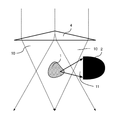
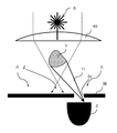
도 1은 본 발명의 일 실시예에 따른 방법 및 장치에 대한 개략도이다.1 is a schematic diagram of a method and apparatus according to an embodiment of the present invention.
공간적 범위를 갖는 생물학적 샘플(1)에서의 움직임의 광학적인 시험관내 검출을 위한 검출장치(100)가 상기 방법을 수행하기 위해 제공된다.A detection device (100) for optical in vitro detection of motion in a biological sample (1) having a spatial extent is provided for carrying out the method.
검출장치(100)는 3 차원 샘플(1) 용의 리셉터클(도시되지 않음), 광원(6), 광학 요소(7, 8) 및 검출기(2)를 포함한다.The
리셉터클은 특정 유형의 리셉터클에 국한되지 않고, 예를 들어 캐리어, 캐리어 플레이트, 용기로서, 멀티 웰 플레이트의 캐비티로서 또는 샘플의 적용 및 유형에 따라 편리하게 설계될 수 있다. 샘플이 성장되는 생체 고분자의 형태, 예를 들어 알긴산 염 형태의 캐리어 매트릭스로서 존재할 수 있다.The receptacle is not limited to a particular type of receptacle and may be conveniently designed, for example, as a carrier, a carrier plate, a container, a cavity of a multi-well plate, or depending on the application and type of sample. The sample may be present in the form of a biomolecule to be grown, for example as a carrier matrix in alginate form.
광원(6)은 간섭성(coherent) 광원, 예를 들면 레이저 일 수 있지만, 반드시 그러할 필요는 없다. 움직임 검출을 위해 샘플의 회절 패턴을 사용하는 실시예(도 4a 내지 도 4c, 도 5a 내지 도 5c를 비교)는 간섭형 방사선을 필요로 한다.The
도 1의 광학 요소(7, 8)의 설명은 단지 개략적인 것으로서, 특정한 광학 요소 변형예가 다수 가능하므로 특정 광학 요소를 설명하기보다는 광학 요소의 기능적 특성을 설명하기 위한 것이다. 이하의 도면에서는 예시로서 도시되어 있다.The description of the
광학 요소의 이러한 기능 특성은 하나 이상의 적절하게 배열되고 설계된 공지된 광학 구성 요소, 예를 들어 필터, 렌즈, 개구, 굴절 소자 등과 같은 구성 요소를 사용하여 실현될 수 있다.These functional characteristics of the optical element can be realized using one or more appropriately arranged and designed known optical components, such as filters, lenses, apertures, refractive elements, and the like.
광학 요소(7, 8)는 조사 측에 배치된 조명 광학 요소(7)를 포함하며, 상기 광학 요소를 사용하여 샘플을 완전히 균일하게 가능한 한 조명하기 위해 광선 광원(6)의 방사선(10)이 전체 샘플(1) 상에 안내된다. 조명 광학 요소는 이에 대한 방사선을 형성하기 위한 개구, 렌즈 및/또는 필터와 같은 적절한 광학 요소 또는 구성 요소를 포함할 수 있다. 액시콘(axicon)의 사용은 특히 유리하다.The
광학 요소(7, 8)는 검출 광학 요소(8)를 더 포함하며, 상기 검출 광학 요소(8)에 의해 샘플로부터 방출되는 광(11), 즉 방사 방향, 편광 상태 및/또는 샘플(1)과의 상호 작용에 의한 회절 패턴으로 변경된 광원(6)으로부터의 광은 검출기(2)의 검출 표면(2a) 상으로 유도된다. 도 1에서, 산란 이벤트는 예를 들어 포인트 (P1)에서 도시되고, 여기서 광(11)은 검출기(2)의 방향으로 산란되고 그리고 검출 광학 요소(8)에 의해 검출기(2)에 맵핑된다. 전체 샘플(1)이 균일하게 조명됨에 따라, 샘플(1) 내의 임의의 지점에서 입사광(10)이 상호 작용이 발생할 수 있으므로 샘플과 광과의 상호 작용이 검출기 (2)에 의해 누적된 방식으로 샘플을 통과하는 전체 경로를 가로질러 측정된다.The
검출 광학 요소(8)는 또한 샘플과의 상호 작용을 통해 방사선 방향, 편광 상태 및/또는 회절 패턴이 변경되지 않은 광이 검출기(2)에 도달하지 않도록 하는 광학 요소를 더 포함할 수 있다. 검출 광학 요소(8)는 예를 들어, 실내 광을 걸러내거나 억제하지만 광원(6)의 파장을 갖는 광을 통과시키는 검출기 입구 앞에 배치된 대역 통과 필터를 포함할 수 있다. 이것은 단색광 광원이 사용되거나 상응하는 필터가 특정 광 파장 만을 갖는 샘플을 조명하기 위해 광원의 출구에 배열된다는 것으로 가정한다.The detecting
검출 광학 요소(8)는 또한 조리개(어퍼쳐)(aperture), 렌즈 등에 의해 광선 경로를 차단할 수 있으며, 샘플(1)에 의해 투과된 광원(6)로부터의 방사선을 검출기에 도달시키고 그리고/또는 광원(6)으로부터의 광을 샘플을 우회하는 동안 검출기(2)에 도달시킨다.The detection
부가적으로 또는 대안적으로, 검출기는 예를 들어 도 1에 도시된 바와 같이 조명 빔 경로(10)에 대해 측면 상에 검출기(2)를 배치함으로써 투과광(12)이 그 검출기 표면(2a)에 도달하지 않도록 배열될 수 있다.Additionally or alternatively, the detector may be arranged such that the transmitted
검출기(2)는 검출된 방사선(11)에 따라 측정 신호(9)를 생성하도록 구성되며, 이것의 시간 프로파일은 검출된 방사선(11)의 강도의 시간 프로파일을 특정한다.The
따라서 검출기 신호(9)는 샘플의 체적 측정(전체 체적 측정)과 동일하다. 검출기(2)는 단일 채널 검출기인 것이 바람직하며, 따라서 시간 단위당 검출기에 의해 기록된 광 강도의 변동과 동일한 단 하나의 측정 파라미터(9)만이 생성된다. 검출기(2)는 예를 들어 종래의 포토다이오드(2)이다.Thus, the
샘플(1)은 도 1에 도시된 검출 장치(100)로 조명되고 대응하는 측정 신호(9)가 평가된다.The
움직임이 현재 샘플(1)에서 발생하는 경우, 예를 들어 배양된 근육 조직의 경우 수축인 경우 샘플에 도달하는 빛과 샘플(1)의 상호 작용 또한 움직임에 의해 변경된다. 즉 샘플(1)과의 상호 작용을 통해 방사선 방향, 그것의 편광 상태 및/또는 회절 패턴으로 변화된 샘플 상에 낙하하는 빛(11)의 비율은 변화하여 검출기 신호(9)에 변화를 발생시킬 수 있다. 상기 방법에 따르면, 생물학적 샘플에서의 움직임은 따라서 검출기 신호(9)의 변동에 의해 검출될 수 있다.The interaction of the
이하, 도 1에 도시된 솔루션 접근법의 특정 설계를 나타내는 본 발명의 실시예의 일부 예를 설명할 것이다. 광원(6)는 도 2a 내지 도 3c에는 도시되어 있지 않지만, 빔 경로(10)로부터 명확한 도시된 광학 및 검출기 구성 위에 위치된다.Some examples of embodiments of the present invention will now be described, illustrating a particular design of the solution approach shown in FIG. The
도 2a 내지 도 2e는 움직임 검출을 위해 샘플에 의해 산란된 광을 사용하는 본 발명의 실시예를 나타낸다. 도 2a 내지 도 2b에서, 검출기(2)는 샘플(2)의 산란광(11)의 투과광 검출을 위해 샘플(1)에 투과된 광 방향으로 배열된다. 샘플(2)을 통해 투과된 빔이 검출기(2)에 도달하는 것을 막기 위해 샘플(2)을 통해 투과된 빔 또는 샘플의 측면을 통과하여 검출기(2)에 도달할 수 있는 빔으로서 검출기(2)에 도달할 광 빔을 차단하는 조리개(어퍼쳐)(3)가 도 2a에 배열된다. 따라서, 조리개(어퍼쳐)(3) 형태의 조명 광학 요소는 검출기(12)에 도달하지 않을 샘플을 통해 투과된 방사선(12)만을 허용한다.2A-2E illustrate an embodiment of the invention using light scattered by a sample for motion detection. 2A and 2B, the
도 2b에 도시된 실시예의 특수성은 조명의 방향을 변화시키는 굴절 광학 요소, 예를 들어 렌즈, 액시콘 등에 의해 추종되는 큰 조리개(어퍼쳐)(3)의 대신에 작은 조리개(어퍼쳐)(3)가 사용되며, 이는 샘플(2)을 통해 투과된 광(12)이 검출기(2)에 도달할 수 없도록 조리개(어퍼쳐)(3)를 통해 입사되는 빔 경로(10)의 방향으로 변화한다는 것이다.The particularity of the embodiment shown in Fig. 2b is that a small aperture (aperture 3) is used in place of a large aperture (aperture) 3 followed by a refractive optical element, for example a lens, axicon or the like, Is used which changes in the direction of the
도 2c에 도시된 실시예의 특수성은 샘플(1)로부터의 반사 형태의 산란광의 표면 검출을 위한 광원(6)와 동일한 샘플(1)의 측면 상에 검출기(2)가 배치되고, 검출기 표면(2a)은 차례로 샘플(2)에 대면한다. 이는 투과광을 차단하기 위한 조리개(어퍼쳐)이 필요 없다는 이점을 제공한다. 그럼에도 불구하고, 검출기(2)를 에워싸는 조리개(어퍼쳐)가 여기에서 구상되고, 간섭 광 영향의 영향을 감소시킬 수 있다.The particularity of the embodiment shown in Figure 2c is such that the
도 2d 및 도 2e에 도시된 실시예 변형의 특징은 산란된 광(11)이 측면에서 검출된다는 것이다. 이를 위해, 검출기(2)는 조명 방향 측에 배치된다. 도 2d에서, 굴절 광학 요소, 예를 들어 렌즈 또는 프리즘(4)은 광선 경로와 샘플(1) 사이에 배치되어, 광선 경로의 방향을 변화시켜 조명 광선 경로(10)의 광선이 도달하지 못하도록 한다. 즉 샘플(1)을 우회하는 동안 검출기(2)에 직접 연결된다.A feature of the embodiment variant shown in Figures 2d and 2e is that the
도 2e에 도시된 실시예는 굴절 광학 요소(4) 대신에 조리개(어퍼쳐)(3a)가 사용되는데, 굴절 광학 요소(4)는 빔 경로(10)를 좁히기 위한 개구를 가지므로, 조명 빔 경로(10)의 광이 샘플(1)을 우회하는 동안 다시 검출기(2)에 직접 도달하지 않게끔 한다.The embodiment shown in Figure 2e uses an
도 3a 내지 도 3c는 움직임 검출을 위해 편광된 광을 사용하는 본 발명의 실시예를 나타낸다. 이를 위해, 조명 광학 요소는 광원와 샘플 (1) 사이에 배치된 제 1 편광 필터 (5a)를 포함한다. 검출 광학 요소는 제 1 편광 필터(5a)와 비교하여 상이한 편광 방향을 갖는 제 2 편광 필터(5b)를 포함하여 샘플(1)과 검출기(2), 바람직하게는 검출기 입구에 위치한다.Figures 3A-3C illustrate an embodiment of the invention using polarized light for motion detection. To this end, the illumination optical element comprises a first
검출기(2) 및 제 2 편광 필터(5b)는 광원 소스에 대해 샘플(1)의 반대측, 샘플(1)의 측면 또는 광원과 동일한 측면 상에 배치될 수 있으며, 도 3a 내지 도 3c에서 다른 변형예를 도시한다.The
2 개의 편광 필터(5a 및 5b)의 상이한 편광 방향으로 인해, 편광 필터(5b)는 샘플 통과와의 상호 작용을 통해 "편광없는" 광 만을 허용한다. 따라서, 2 개의 편광 필터(5a 및 5b)의 배열은 샘플을 통해 투과된 광 또는 샘플을 바이패스한 광이 검출되지 않도록 보장한다.Due to the different polarization directions of the two
샘플에서의 움직임은 무 편광 광의 비율을 변화시키고 검출기 신호의 변동을 야기하므로, 샘플(1)에서의 움직임은 검출기 신호의 변동으로부터 직접 검출될 수 있다.Since the motion in the sample changes the ratio of the unpolarized light and causes the fluctuation of the detector signal, the motion in the
샘플상의 조명 빔 경로(10)를 포커싱하는 굴절 광학 요소(4), 예를 들어 볼록 렌즈 또는 프리즘은 산란 광 효과를 감소시키기 위해 제 1 편광 필터(5a) 앞에 배열될 수 있다(도 3a 및 도 3c).The refractive
도 3b의 실시예에서, 검출기(2)는 샘플(1)로부터의 반사의 형태로 산란된 광의 표면 검출을 위해 광원(6)과 같은 샘플(1)의 측면 상에 배치된다. 검출기(2)를 둘러싸는 조리개(어퍼쳐)(3)는 여기서 예상되는 간섭성 광 영향의 영향을 줄일 수 있다.3B, the
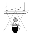
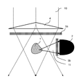
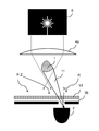
도 4a 내지 도 4c는 움직임 검출을 위해, 예를 들어 스펙클 패턴의 형태로 샘플의 회절 패턴을 사용하는 본 발명의 실시예를 나타낸다. 광원(6)은 예를 들어 레이저 다이오드와 같은 간섭성 광원이다. 샘플에서 회절된 광원(6)의 광은 강도가 높은 중심(Z) 및 낮은 강도의 에지 영역(R)을 갖는 회절 패턴을 생성한다.Figures 4A-4C illustrate embodiments of the present invention for use in motion detection, e.g., using a diffraction pattern of a sample in the form of a speckle pattern. The
검출 광학기구는 핀홀 조리개(어퍼쳐)(3b)의 핀홀(3c)이 샘플에 의해 생성된 회절 패턴의 에지 영역(R)에 배치되도록 샘플(1)과 검출기(2) 사이에 배치된 검출기(2)의 전방에 배치된 핀홀 조리개(어퍼쳐)(3b)를 포함한다. The detection optical mechanism is constructed such that the
도 4a의 변형예에 따르면, 조명 광학기구는 광원과 샘플 사이에 배치된 조리개(어퍼쳐)(3a)를 포함하며, 조리개(어퍼쳐)(3a)의 조리개(어퍼쳐) 개구(3d)를 통해 방출하는 상기 광원(6)로부터의 방사선은 핀홀 조리개(어퍼쳐)(3b)의 핀홀(3c)에 직접적으로 도달하지 않는 형식으로 형성된다.According to a variant of figure 4a, the illumination optics comprise an aperture (3a) arranged between the light source and the sample and the apertures (3d) of the aperture (3a) The radiation from the
도 4b 및 도 4c의 변형예에 따르면, 조명 광학기구는 광원(6)과 샘플(1) 사이에, 예를 들어 오목 렌즈와 같은 굴절 광학 요소(4a)를 포함하며, 굴절 광학 요소(4a)는 핀홀 조리개(어퍼쳐)(3b)의 핀홀(3c)에 직접 도달하지 않고, 즉 샘플을 바이패스한다.According to a variant of Figures 4b and 4c, the illumination optics comprise a refractive
도 4c의 변형예에서, 대역 통과 필터(13)는 또한 샘플(1)과 광원(6)의 파장과 동일하지 않은 실내 광을 걸러내는 핀홀 조리개(어퍼쳐)(3b) 사이에 배치된다. 심장 박동은 현재 도 4c에 도시된 구성으로 육안 관찰(현미경으로 관찰)에 필적하는 감도로 검출될 수 있다.In the modification of Fig. 4C, the band-
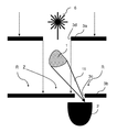
도 5c는 세포 클러스터(cell cluster) 형태의 샘플(1)의 예를 도시한다. 세포 클러스터는 현적형 드롭에 위치하며, 그 일부만이 도 5a에서 볼 수 있으며, 현적형 드롭 다중 역가 플레이트의 캐비티 내에 형성된다. 샘플은 줄기 세포로부터 분화된 심장 근육 조직 모델로 구성되며, 알긴산 염 형태로 캐리어 비드(15)에 부착한다. 도 5a에 도시된 샘플은 약 1 밀리미터의 직경을 갖는다.Figure 5C shows an example of a sample (1) in the form of a cell cluster. The cell clusters are located in the current drop, only a portion of which can be seen in Figure 5a and are formed in the cavity of the current drop drop multiplexer plate. The sample is composed of a cardiac muscle tissue model differentiated from stem cells and attached to
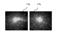
샘플(1)은 레이저 다이오드로 650nm 파장의 광으로 완전히 조명된다. 서로 다른 크기의 스케일로 구성된 샘플(1)은 다양한 방식으로 간섭성 광을 회절시키고 투과광 방향으로 복잡한 회절 패턴(소위 "스펙클 패턴")을 생성한다. 국소 심장 근육 수축으로 인한 조직 내에서의 이러한 구조의 작은 변형은 전체 스펙클 패턴의 변화로 이어진다.The sample (1) is completely illuminated with light having a wavelength of 650 nm by a laser diode. The
도 5b는 수축의 최소 및 최대 편향에서의 스펙클 패턴의 2 개의 상이한 조건을 나타내는 예로서의 이미지(17a 및 17b)를 도시한다. 이미지(17a 및 17b)는 설명을 위해서만 사용되며, 다른 실험에서 기인한 것으로,도 5a의 샘플(1)의 스펙클 패턴을 나타내지 않는다. 그러나 측정 원리는 동일하다. 회절 패턴(17a, 17b)의 에지 영역(R)의 점은 공간 필터, 예를 들어 핀홀 조리개(어퍼쳐)(3b)에 의해 검출기(2) 상에 도시된다. 패턴(17a, 17b)의 변화는 이제 핀홀 조리개(어퍼쳐)(3b)에 의해 통과하는 변동 광량으로 이어지고, 따라서 도 5c에 도시된 변동하는 검출기 신호(9)로 이어진다. 신호(9)의 주기적인 변동은 근육 조직의 주기적인 수축과 동일하다. 도 5c의 예시는 설명을 위한 것일 뿐이며,도 1a에 도시된 샘플의 조명 동안 측정된 측정 신호도 나타내지 않는다.Figure 5b shows
본 발명이 특정 실시예를 참조하여 설명되었지만, 본 발명의 범위를 벗어나지 않고 다른 변경이 수행될 수 있고 등가물이 대체물로서 사용될 수 있음은 당업자에게 명백하다. 또한 많은 수정이 관련 범위를 벗어나지 않고 수행될 수 있다. 결론적으로, 본 발명은 개시된 실시예에 한정되지 않고, 첨부된 특허청구범위에 속하는 모든 실시예를 포함해야 한다. 본 발명은 특히, 청구된 청구범위에 관계없이, 대상에 대한 보호 및 종속 관계의 특성을 모두 청구한다.While the invention has been described with reference to specific embodiments, it is evident to those skilled in the art that other changes may be made and equivalents may be substituted as substitutes without departing from the scope of the invention. Many modifications may also be made without departing from the scope of the invention. In conclusion, the present invention is not limited to the disclosed embodiments, but should include all embodiments falling within the scope of the appended claims. The present invention particularly claims all the characteristics of the protection and dependency on the object, regardless of the claimed claims.
Claims (19)
a) 샘플(1), 광원(6), 광학기구(7, 8; 3, 3a, 3b, 4, 5a, 5b) 및 검출기(2)를 위한 리셉터클을 제공하는 단계로서,
a1) 상기 광학기구(7, 8)는 상기 광원으로부터 나오는 방사선으로 상기 리셉터클 내의 전체 샘플(1)을 조명하고 상기 광원(6)으로부터 상기 방사선의 적어도 일부를 유도하도록 구성되고, 샘플(1)과의 상호 작용을 통해 샘플(1) 내의 임의의 지점에서 검출기(2)의 검출 표면(2a)으로 방사 방향, 편광 상태 및/또는 회절 패턴이 변경되며,
a2) 상기 검출기(2)는 검출된 방사선에 따라 측정 신호(9)를 생성하도록 구성되는 것으로, 상기 검출된 방사선의 강도의 시간 프로파일을 특정하고 그리고/또는 검출된 방사선(11)의 강도의 시간 프로파일이 도출될 수 있고;
b) 상기 광원으로부터의 방사선으로 상기 샘플(1)을 조명하는 단계; 및
c) 측정 신호(9)의 시간 변화에 따라 생물학적 샘플(1)에서의 움직임을 검출하는 단계를 포함하는 것을 특징으로 하는 검출 방법.
1. An optical in vitro detection method for movement in a biological sample (1) having a spatial extent in the form of a three-dimensional cell and / or tissue culture or cell cluster or a free-swimming microorganism sample,
a) providing a receptacle for the sample 1, the light source 6, the optical instruments 7, 8; 3, 3a, 3b, 4, 5a, 5b and the detector 2,
a1) the optical mechanism (7,8) is configured to illuminate the entire sample (1) in the receptacle with radiation coming from the light source and to guide at least a part of the radiation from the light source (6) The polarization state and / or the diffraction pattern is changed from the arbitrary point in the sample 1 to the detection surface 2a of the detector 2 through the interaction of the polarization state and /
a2) said detector (2) being adapted to generate a measurement signal (9) in accordance with the detected radiation, characterized in that it comprises means for specifying a time profile of the intensity of said detected radiation and / A profile can be derived;
b) illuminating the sample (1) with radiation from the light source; And
c) detecting a movement in the biological sample (1) in accordance with a change in the time of the measurement signal (9).
상기 샘플의 직경은
a) 적어도 하나의 공간 방향에서 적어도 50 마이크로미터(㎛), 또는
b) 100 ㎛에서 1 mm의 범위 내에 있는 것을 특징으로 하는 검출 방법.
The method according to claim 1,
The diameter of the sample
a) at least 50 micrometers (m) in at least one spatial direction, or
b) is within the range of 100 [mu] m to 1 mm.
상기 샘플은
a) 생체 세포, 예를 들어 근육 세포, 및/또는
b) 움직임을 유발할 수 있는 세포를 포함하는 것을 특징으로 하는 검출 방법.3. The method according to claim 1 or 2,
The sample
a) a biological cell, such as a muscle cell, and / or
b) a cell capable of inducing movement.
a) 상기 검출기(2)는 단일-채널 측정 신호(9)를 방출하고; 그리고/또는
b) 상기 검출기(2)는 포토다이오드이고; 그리고/또는
c) 상기 검출기(2)는 비-이미징 검출기 또는 비 공간적으로 분해된 측정 신호를 갖는 검출기 인 것을 특징으로 하는 검출 방법.
10. A method according to any one of the preceding claims,
a) the detector (2) emits a single-channel measurement signal (9); And / or
b) said detector (2) is a photodiode; And / or
c) said detector (2) is a non-imaging detector or a detector with a non-spatially resolved measurement signal.
a) 상기 광학기구(7, 8)는 샘플(1)을 통해 투과된 광원(6)의 상기 방사선(12)이 상기 검출기에 도달하는 위치에 그리고/또는 샘플을 우회하는 동안 상기 광원로부터의 광이 상기 검출기에 도달하는 위치에 어떠한 빔 경로도 존재하지 않게끔 구성되는 방도로 상기 조명 빔 경로(10) 및 상기 샘플(2)에 대해 배치되고; 그리고/또는
b) 상기 샘플(1)이 완전히 조명되는 것을 특징으로 하는 검출 방법.
10. A method according to any one of the preceding claims,
characterized in that a) the optics (7,8) are arranged such that the radiation (12) from the light source (6) transmitted through the sample (1) Is arranged with respect to the illumination beam path (10) and the sample (2) in such a way that no beam path exists at the position where it reaches the detector; And / or
b) the sample (1) is fully illuminated.
상기 샘플(1)에서의 움직임이 상기 측정 신호(9)의 변화가 미리 결정된 임계 값을 초과하는 경우 및/또는 상기 측정 신호(9)의 시간적 변화가 측정 신호(9)는 주기성을 갖는 경우에 검출되는 것을 특징으로 하는 검출 방법.
10. A method according to any one of the preceding claims,
If the movement in the sample 1 exceeds a predetermined threshold value of the measurement signal 9 and / or if the temporal variation of the measurement signal 9 has a periodicity Is detected.
a) 상기 광원(6)은 간섭성 광선을 생성하고, 그리고
b) 상기 광학기구(7, 8)는 상기 샘플에 의해 회절된 상기 광원으로부터의 광에 의해 생성된 회절 패턴의 에지 영역을 상기 검출기 상에 맵핑하도록 구성되는 것을 특징으로 하는 검출 방법.
10. A method according to any one of the preceding claims,
a) the light source (6) generates a coherent light beam, and
b) The optical device (7,8) is configured to map an edge region of the diffraction pattern produced by the light from the light source diffracted by the sample onto the detector.
상기 광학기구는 상기 샘플(1)과 상기 검출기(2) 사이에 배치된 핀홀 조리개(어퍼쳐)(3b)를 포함하여 상기 핀홀 조리개(어퍼쳐)(3b)의 핀 홀(3c)이 샘플에 의해 생성된 회절 패턴의 에지 영역 (R)에 배치되도록 한 것을 특징으로 하는 검출 방법.
8. The method of claim 7,
The optical mechanism includes a pinhole stopper (aperture) 3b disposed between the sample 1 and the detector 2 such that the pinhole 3c of the pinhole stopper (aperture) Is arranged in the edge region (R) of the diffraction pattern generated by the diffraction pattern.
상기 광학기구는,
a) 조리개(어퍼쳐) 개구(3d)를 통해 존재하는 상기 광원(6)으로부터의 방사선이 핀홀 조리개(어퍼쳐)(3b)의 핀홀 (3c)을 직접 도달하지 않는 방도로 상기 광원과 상기 샘플 사이에 배치된 조리개(어퍼쳐)(3a), 및/또는
b) 회절된 방사선이 핀홀 조리개(어퍼쳐)(3b)의 핀홀(3c)에 도달하지 않는 방도로 광원(6)과 샘플(1) 사이에 배치된 굴절 광학 요소(4a)를 포함하는 것을 특징으로 하는 검출 방법.
9. The method of claim 8,
Wherein the optical mechanism includes:
a) the light from the light source 6 existing through the apertures 3d passes through the pinhole 3c of the pinhole aperture (aperture) 3b in such a way that the radiation from the light source 6 does not directly reach the pinhole 3c of the pinhole aperture (Aperture) 3a disposed between the diaphragms 3a and /
b) a refractive optical element 4a disposed between the light source 6 and the sample 1 in such a way that the diffracted radiation does not reach the pinhole 3c of the pinhole aperture (aperture) 3b .
상기 광학기구는 상이한 편광 방향을 갖는 제 1 편광 필터(5a) 및 제 2 편광 필터(5b)를 포함하고, 상기 제 1 편광 필터(5a)는 광원(6)과 샘플(1) 사이에 그리고 제 2 편광 필터(5b)는 샘플(1)과 검출기(2) 사이에 배치되는 것을 특징으로 하는 검출 방법.
10. A method according to any one of the preceding claims,
The optical device includes a first polarizing filter 5a and a second polarizing filter 5b having different polarization directions and the first polarizing filter 5a is disposed between the light source 6 and the sample 1, And a two-polarization filter (5b) is arranged between the sample (1) and the detector (2).
a) 상기 검출기(2)는 상기 샘플(1)에 의해 확산된 광의 에피디텍션(epidetection)을 위해 상기 광원(6)과 동일한 상기 샘플(1) 측에 배치되고; 그리고/또는
b) 상기 검출기(2)는 상기 조명 빔 경로(10)의 방향에 대해 상기 샘플(1)의 확산 측면 방사선을 검출하기 위해 상기 샘플(2)의 측면에 배치되고; 그리고/또는
c) 상기 검출기(2)는 샘플(2)에 의해 확산된 광의 투과광 검출을 위해 샘플(1)의 투과광 방향으로 배열되고, 상기 광학기구는
c1) 샘플을 통해 투과된 빔으로서 검출기(2)에 도달할 수 있는 조명 빔 경로 내의 광 빔을 차단하도록 설계된 광원(6)와 샘플(1) 사이에 배치된 것으로, 샘플을 통해 투과된 빔으로서 검출기(2)에 도달할 수 있는 조명 빔 경로 내의 광 빔을 차단하도록 설계된 조리개(어퍼쳐)(3)을 포함하고, 그리고/또는
c2) 상기 광원(6)과 상기 샘플(2) 사이에 배치된 것으로서, 상기 샘플(1)을 통해 투과된 광선이 검출기(2)에 도달하지 않는 방도로 상기 조명 빔 경로의 방향을 변경시키도록 설계된 굴절 요소(4)를 포함하는 것을 특징으로 하는 검출 방법.
10. A method according to any one of the preceding claims,
a) the detector (2) is arranged on the same side of the sample (1) as the light source (6) for epidetection of light diffused by the sample (1); And / or
b) said detector (2) is arranged on the side of said sample (2) for detecting the diffuse lateral radiation of said sample (1) with respect to the direction of said illumination beam path (10); And / or
c) The detector (2) is arranged in the direction of the transmitted light of the sample (1) for the detection of transmitted light of the light diffused by the sample (2)
c1) arranged between the sample (1) and a light source (6) designed to block the light beam in the illumination beam path that can reach the detector (2) as a beam transmitted through the sample, (Aperture) 3 designed to block the light beam in the illumination beam path that can reach the detector 2, and / or
c2) to change the direction of the illumination beam path in such a way that light rays transmitted through the sample (1) do not reach the detector (2), arranged between the light source (6) and the sample Characterized in that it comprises a designed refractive element (4).
상기 광학기구는 상기 검출기(2) 앞에 배치되고 실내 광을 억제하도록 설계된 대역 통과 필터(13)를 포함하는 것을 특징으로 하는 검출 방법.
10. A method according to any one of the preceding claims,
Characterized in that the optical device comprises a band-pass filter (13) arranged in front of the detector (2) and designed to suppress room light.
a) 샘플용 리셉터클이 캐리어 매트릭스, 바람직하게는 바이오폴리머(15)를 포함하고; 그리고/또는
b) 샘플용 리셉터클이 현적형 드롭(hanging drop)을 포함하는 것을 특징으로 하는 검출 방법.
10. A method according to any one of the preceding claims,
a) the receptacle for the sample comprises a carrier matrix, preferably a biopolymer (15); And / or
b) the receptacle for the sample comprises a hanging drop.
상기 샘플용 리셉터클은 멀티-웰 플레이트 또는 현적형 드롭 멀티-웰 플레이트의 캐비티 인 것을 특징으로 하는 검출 방법.
10. A method according to any one of the preceding claims,
Wherein the receptacle for the sample is a cavity of a multi-well plate or a current drop multi-well plate.
움직임의 병행 광학 검출이 서로 분리된 몇몇 생물학적 샘플에서 수행되고,
샘플용 리셉터클은 멀티-웰 플레이트 또는 현적형 드롭 멀티-웰 플레이트로서, 행렬로 배열된, 샘플을 수용하기 위한 다수의 캐비티를 가지며,
검출기는 검출기 어레이로서, 바람직하게는 포토다이오드 어레이로서 설계되며, 개별 검출기의 그리드 거리는 멀티-웰 플레이트의 캐비티의 그리드 거리와 동일한 것을 특징으로 하는 검출 방법.
10. A method according to any one of the preceding claims,
Concurrent optical detection of motion is performed on several biological samples separated from each other,
The receptacle for a sample is a multi-well plate or a current drop multi-well plate, arranged in a matrix, having a plurality of cavities for receiving a sample,
The detector is designed as a detector array, preferably as a photodiode array, the grid distance of the individual detector being equal to the grid distance of the cavity of the multi-well plate.
상기 광원은 캐비티 내의 샘플을 조명하기 위한 레이저 다이오드 어레이로서 설계되고, 개별 레이저 다이오드의 그리드 거리는 멀티-웰 플레이트의 캐비티의 그리드 거리와 동일하고 렌즈는 레이저 다이오드의 빛을 캐비티로 안내하는 것을 특징으로 하는 검출 방법.
16. The method of claim 15,
Wherein the light source is designed as a laser diode array for illuminating a sample in a cavity, the grid distance of the individual laser diode being equal to the grid distance of the cavity of the multi-well plate, and the lens guiding the light of the laser diode to the cavity Detection method.
a) 상기 레이저 다이오드 어레이의 홀더는 열전도성 재료, 바람직하게는 알루미늄으로 제조되며; 그리고/또는
b) 상기 광학기구는 마이크로 렌즈 어레이를 포함하며, 상기 렌즈 어레이의 각 렌즈는 상기 레이저 다이오드 중 하나에 할당되는 것을 특징으로 하는 검출 방법.
17. The method of claim 16,
a) the holder of the laser diode array is made of a thermally conductive material, preferably aluminum; And / or
b) said optical mechanism comprises a microlens array, wherein each lens of said lens array is assigned to one of said laser diodes.
상기 광원의 광은 광섬유 번들에 의해 상기 샘플을 조명하기 위해 상기 샘플을 포함하는 개별 캐비티에 결합되는 것을 특징으로 하는 검출 방법.
16. The method of claim 15,
Wherein the light of the light source is coupled to an individual cavity comprising the sample to illuminate the sample with an optical fiber bundle.
- 생물학적 샘플 (1) 용 리셉터클 (15, 16),
- 광원(6),
- 검출기 (2),
- 광학기구(7, 8)를 포함하고,
상기 광학기구(7, 8)는 상기 광원으로부터 나오는 방사선으로 상기 리셉터클 내의 전체 샘플(1)을 조명하고 상기 광원(6)으로부터 상기 방사선(11)의 적어도 일부를 유도하도록 구성되고, 샘플(1)과의 상호 작용을 통해 샘플(1) 내의 임의의 지점에서 검출기(2)의 검출 표면(2a)으로 방사 방향, 편광 상태 및/또는 회절 패턴이 변경되며, 상기 검출기(2)는 검출된 방사선(11)에 따라 측정 신호(9)를 생성하도록 구성되는 것으로, 상기 검출된 방사선의 강도의 시간 프로파일을 특정하고 그리고/또는 검출된 방사선(11)의 강도의 시간 프로파일이 도출될 수 있고, 상기 검출된 방사선의 시간 변화를 디스플레이 및/또는 평가함으로써 상기 생물학적 샘플 내의 움직임을 검출하도록 구성된 평가 유닛을 더 포함하는 것을 특징으로 하는 검출 장치.
A contactless in vitro detection device for movement in a biological sample having spatial extent in the form of three-dimensional cells and / or tissue cultures or cell clusters or free-floating microbial samples,
- receptacles (15, 16) for biological samples (1)
A light source 6,
- detectors (2),
- an optical device (7, 8)
Wherein the optical instrument is configured to illuminate the entire sample in the receptacle with radiation from the light source and to guide at least a portion of the radiation from the light source, The polarization direction and / or the diffraction pattern are changed from the arbitrary point in the sample 1 to the detection surface 2a of the detector 2 through interaction with the detector 2, Characterized in that the time profile of the intensity of the detected radiation is specified and / or a time profile of the intensity of the detected radiation (11) can be derived, and the detection Further comprising an evaluation unit configured to detect movement in the biological sample by displaying and / or evaluating a temporal change in the emitted radiation.
Applications Claiming Priority (3)
| Application Number | Priority Date | Filing Date | Title |
|---|---|---|---|
| DE102015003019.1A DE102015003019A1 (en) | 2015-03-06 | 2015-03-06 | Method and device for the optical detection of movement in a biological sample with spatial extent |
| DE102015003019.1 | 2015-03-06 | ||
| PCT/EP2016/000377 WO2016142043A1 (en) | 2015-03-06 | 2016-03-02 | Method and device for optical detection of a movement in a biological sample with a spatial extent |
Publications (1)
| Publication Number | Publication Date |
|---|---|
| KR20170140182A true KR20170140182A (en) | 2017-12-20 |
Family
ID=55456746
Family Applications (1)
| Application Number | Title | Priority Date | Filing Date |
|---|---|---|---|
| KR1020177027379A KR20170140182A (en) | 2015-03-06 | 2016-03-02 | Method and apparatus for optical detection of motion of biological samples with spatial extent |
Country Status (8)
| Country | Link |
|---|---|
| US (1) | US10488400B2 (en) |
| EP (2) | EP4242637A3 (en) |
| JP (1) | JP6851328B2 (en) |
| KR (1) | KR20170140182A (en) |
| CN (1) | CN107430064B (en) |
| DE (1) | DE102015003019A1 (en) |
| ES (1) | ES2961352T3 (en) |
| WO (1) | WO2016142043A1 (en) |
Families Citing this family (30)
| Publication number | Priority date | Publication date | Assignee | Title |
|---|---|---|---|---|
| KR20190117519A (en) * | 2017-02-10 | 2019-10-16 | 암겐 인코포레이티드 | Imaging System for Counting and Sizing Particles in Fluid-Filled Vessels |
| US10088660B2 (en) | 2017-02-10 | 2018-10-02 | Amgen Inc. | Imaging system for counting and sizing particles in fluid-filled vessels |
| JP2021508542A (en) * | 2017-12-27 | 2021-03-11 | エシコン エルエルシーEthicon LLC | Hyperspectral imaging in a light-deficient environment |
| DE102018111033A1 (en) * | 2018-05-08 | 2019-11-14 | Byonoy Gmbh | Transmission device for the examination of samples in wells of a microtiter plate and method for examining samples in wells of a microtiter plate by means of transmission |
| US11925328B2 (en) | 2019-06-20 | 2024-03-12 | Cilag Gmbh International | Noise aware edge enhancement in a pulsed hyperspectral imaging system |
| US11624830B2 (en) | 2019-06-20 | 2023-04-11 | Cilag Gmbh International | Wide dynamic range using a monochrome image sensor for laser mapping imaging |
| US11674848B2 (en) | 2019-06-20 | 2023-06-13 | Cilag Gmbh International | Wide dynamic range using a monochrome image sensor for hyperspectral imaging |
| US11360028B2 (en) | 2019-06-20 | 2022-06-14 | Cilag Gmbh International | Super resolution and color motion artifact correction in a pulsed hyperspectral, fluorescence, and laser mapping imaging system |
| US11284784B2 (en) | 2019-06-20 | 2022-03-29 | Cilag Gmbh International | Controlling integral energy of a laser pulse in a fluorescence imaging system |
| US11237270B2 (en) | 2019-06-20 | 2022-02-01 | Cilag Gmbh International | Hyperspectral, fluorescence, and laser mapping imaging with fixed pattern noise cancellation |
| US11187658B2 (en) | 2019-06-20 | 2021-11-30 | Cilag Gmbh International | Fluorescence imaging with fixed pattern noise cancellation |
| US11252326B2 (en) | 2019-06-20 | 2022-02-15 | Cilag Gmbh International | Pulsed illumination in a laser mapping imaging system |
| US20200397239A1 (en) | 2019-06-20 | 2020-12-24 | Ethicon Llc | Offset illumination of a scene using multiple emitters in a fluorescence imaging system |
| US11622094B2 (en) | 2019-06-20 | 2023-04-04 | Cilag Gmbh International | Wide dynamic range using a monochrome image sensor for fluorescence imaging |
| US11793399B2 (en) | 2019-06-20 | 2023-10-24 | Cilag Gmbh International | Super resolution and color motion artifact correction in a pulsed hyperspectral imaging system |
| US11758256B2 (en) | 2019-06-20 | 2023-09-12 | Cilag Gmbh International | Fluorescence imaging in a light deficient environment |
| US11612309B2 (en) | 2019-06-20 | 2023-03-28 | Cilag Gmbh International | Hyperspectral videostroboscopy of vocal cords |
| US11550057B2 (en) | 2019-06-20 | 2023-01-10 | Cilag Gmbh International | Offset illumination of a scene using multiple emitters in a fluorescence imaging system |
| US11898909B2 (en) | 2019-06-20 | 2024-02-13 | Cilag Gmbh International | Noise aware edge enhancement in a pulsed fluorescence imaging system |
| US11716543B2 (en) | 2019-06-20 | 2023-08-01 | Cilag Gmbh International | Wide dynamic range using a monochrome image sensor for fluorescence imaging |
| US11754500B2 (en) | 2019-06-20 | 2023-09-12 | Cilag Gmbh International | Minimizing image sensor input/output in a pulsed fluorescence imaging system |
| US11096565B2 (en) | 2019-06-20 | 2021-08-24 | Cilag Gmbh International | Driving light emissions according to a jitter specification in a hyperspectral, fluorescence, and laser mapping imaging system |
| US11931009B2 (en) | 2019-06-20 | 2024-03-19 | Cilag Gmbh International | Offset illumination of a scene using multiple emitters in a hyperspectral imaging system |
| US11700995B2 (en) | 2019-06-20 | 2023-07-18 | Cilag Gmbh International | Speckle removal in a pulsed fluorescence imaging system |
| US11141052B2 (en) | 2019-06-20 | 2021-10-12 | Cilag Gmbh International | Image rotation in an endoscopic fluorescence imaging system |
| US11903563B2 (en) | 2019-06-20 | 2024-02-20 | Cilag Gmbh International | Offset illumination of a scene using multiple emitters in a fluorescence imaging system |
| US11671691B2 (en) | 2019-06-20 | 2023-06-06 | Cilag Gmbh International | Image rotation in an endoscopic laser mapping imaging system |
| US20220356435A1 (en) * | 2019-09-26 | 2022-11-10 | Kyocera Corporation | Cell detector and cell detection method |
| US11607188B2 (en) | 2020-06-15 | 2023-03-21 | Eosdx Inc. | Diffractometer-based global in situ diagnostic system |
| WO2021257457A1 (en) * | 2020-06-15 | 2021-12-23 | Bragg Analytics, Inc. | Diffraction-based global in vitro diagnostic system |
Family Cites Families (39)
| Publication number | Priority date | Publication date | Assignee | Title |
|---|---|---|---|---|
| JPS54109488A (en) * | 1978-02-08 | 1979-08-28 | Fuji Photo Optical Co Ltd | Analyzing method and device of optically scattered image information |
| DE7836339U1 (en) * | 1978-12-07 | 1981-07-16 | Kaufmann, Raimund, Dr., 4005 Meerbusch | DEVICE FOR DETERMINING THE SPEED OF PARTICLES MOVING IN A LIQUID |
| JPS6259841A (en) * | 1985-09-10 | 1987-03-16 | Res Dev Corp Of Japan | Method and instrument for measuring immunoreaction using linearly polarized light |
| JPS62116263A (en) * | 1985-11-15 | 1987-05-27 | Olympus Optical Co Ltd | Method and apparatus for measuring immunoreaction using multiple scattering of linearly polarized light |
| JPH0623749B2 (en) * | 1986-03-10 | 1994-03-30 | 新技術事業団 | New spectrophotometric assay for cell damage caused by toxins and drugs |
| JP2949286B2 (en) * | 1987-08-26 | 1999-09-13 | 松下電工株式会社 | Dimmable carbon dioxide concentration sensor |
| DE68924749T2 (en) * | 1988-09-15 | 1996-07-04 | Univ Arkansas | Identification of particles by modulated dynamic light scattering. |
| US5061075A (en) | 1989-08-07 | 1991-10-29 | Alfano Robert R | Optical method and apparatus for diagnosing human spermatozoa |
| US6671540B1 (en) * | 1990-08-10 | 2003-12-30 | Daryl W. Hochman | Methods and systems for detecting abnormal tissue using spectroscopic techniques |
| DE4215908A1 (en) * | 1992-05-14 | 1993-11-18 | Ubbo Prof Dr Ricklefs | Optical particle size measurement appts. e.g. for clean room - periodically modulates light incident on measuring vol. e.g by varying light source power or using grating, acoustic=optic modulator or hologram, and detects scattered light. |
| US5627308A (en) * | 1995-05-31 | 1997-05-06 | Dahneke; Barton E. | Method and apparatus for measuring motion of a suspended particle or a suspending fluid |
| US6096510A (en) * | 1995-10-04 | 2000-08-01 | Cytoscan Sciences, Llc | Methods and systems for assessing biological materials using optical detection techniques |
| JP4169827B2 (en) * | 1997-05-28 | 2008-10-22 | ミクロナス ゲーエムベーハー | measuring device |
| US20060105357A1 (en) * | 1998-02-18 | 2006-05-18 | Myomics, Inc. | Tissue sensor and uses thereof |
| DE19836183A1 (en) * | 1998-08-03 | 1999-03-18 | Gimsa Jan Priv Doz Dr | Device for tracking movement of microscopic and sub-microscopic objects in microscopic volumes |
| US7097974B1 (en) * | 1998-08-28 | 2006-08-29 | Febit Biotech Gmbh | Support for a method for determining an analyte and a method for producing the support |
| US6100976A (en) * | 1998-09-21 | 2000-08-08 | The Board Of Regents For Oklahoma State University | Method and apparatus for fiber optic multiple scattering suppression |
| GB2361772B (en) * | 2000-04-29 | 2004-05-19 | Malvern Instr Ltd | Mobility and effects arising from surface charge |
| JP4384344B2 (en) * | 2000-08-09 | 2009-12-16 | 拓之 今野 | Blood coagulation time measurement method and apparatus using granular spot pattern by laser reflected light |
| DE10041596A1 (en) * | 2000-08-24 | 2002-03-21 | Cellcontrol Biomedical Lab Gmb | Device and method for the spatially resolved examination of networked cells and / or cell systems and use for the examination of active substances |
| JP4334899B2 (en) * | 2003-02-25 | 2009-09-30 | 大塚電子株式会社 | Electrophoretic velocity measuring device |
| GB0307756D0 (en) * | 2003-04-03 | 2003-05-07 | Suisse Electronique Microtech | Measuring the concentration and motility of light scattering particles |
| DE102006003877B4 (en) * | 2005-12-09 | 2007-10-31 | Diehl Bgt Defence Gmbh & Co. Kg | vibrometer |
| JP2010508056A (en) * | 2006-10-30 | 2010-03-18 | エルフィ−テック リミテッド | System and method for in vivo measurement of biological parameters |
| JP5024935B2 (en) * | 2007-01-16 | 2012-09-12 | 富士フイルム株式会社 | Device and method for detecting defect of light transmitting member |
| GB0701201D0 (en) * | 2007-01-22 | 2007-02-28 | Cancer Rec Tech Ltd | Cell mapping and tracking |
| US8821799B2 (en) * | 2007-01-26 | 2014-09-02 | Palo Alto Research Center Incorporated | Method and system implementing spatially modulated excitation or emission for particle characterization with enhanced sensitivity |
| EP2342317B1 (en) | 2008-09-22 | 2012-12-19 | University Of Zurich Prorektorat Forschung | Hanging drop plate |
| CN201311392Y (en) * | 2008-12-11 | 2009-09-16 | 成都恩普生医疗科技有限公司 | Enzyme-labelling measuring instrument optical path detecting system based on LED cold light source |
| CN102341694B (en) * | 2009-01-08 | 2018-03-23 | It-Is国际有限公司 | Optical system for chemical reaction and/or biochemical reaction |
| US8702942B2 (en) * | 2010-12-17 | 2014-04-22 | Malvern Instruments, Ltd. | Laser doppler electrophoresis using a diffusion barrier |
| JP5883233B2 (en) * | 2011-03-16 | 2016-03-09 | 英光 古川 | Scanning microscopic light scattering measurement and analysis apparatus and light scattering analysis method |
| US8772039B2 (en) * | 2011-05-26 | 2014-07-08 | The General Hospital Corporation | Optical thromboelastography system and method for evaluation of blood coagulation metrics |
| DE102011085599B3 (en) | 2011-11-02 | 2012-12-13 | Polytec Gmbh | Apparatus and method for interferometric measurement of an object |
| WO2013065796A1 (en) * | 2011-11-02 | 2013-05-10 | 浜松ホトニクス株式会社 | Observation device |
| DE102012016122A1 (en) * | 2012-08-15 | 2014-02-20 | Westfälische Wilhelms-Universität Münster | Method for detecting e.g. position of insect within observation arena during performing experiments for evaluating biological behavior, involves detecting light scattered due to interrupted reflectance in animal by camera |
| JP6076111B2 (en) * | 2013-02-07 | 2017-02-08 | 浜松ホトニクス株式会社 | Mass cell evaluation method and mass cell evaluation apparatus |
| DE102013211885A1 (en) * | 2013-06-24 | 2014-12-24 | Siemens Aktiengesellschaft | Particle detector and method for the detection of particles |
| DE202014004218U1 (en) * | 2014-05-19 | 2014-05-28 | Particle Metrix Gmbh | Device of particle tracking analysis with the aid of scattered light (PTA) and for the detection and characterization of particles in liquids of all kinds in the order of nanometers |
-
2015
- 2015-03-06 DE DE102015003019.1A patent/DE102015003019A1/en active Pending
-
2016
- 2016-03-02 JP JP2017564793A patent/JP6851328B2/en active Active
- 2016-03-02 US US15/555,773 patent/US10488400B2/en active Active
- 2016-03-02 CN CN201680014161.3A patent/CN107430064B/en active Active
- 2016-03-02 ES ES16708082T patent/ES2961352T3/en active Active
- 2016-03-02 EP EP23182756.9A patent/EP4242637A3/en active Pending
- 2016-03-02 WO PCT/EP2016/000377 patent/WO2016142043A1/en active Application Filing
- 2016-03-02 KR KR1020177027379A patent/KR20170140182A/en unknown
- 2016-03-02 EP EP16708082.9A patent/EP3265779B1/en active Active
Also Published As
| Publication number | Publication date |
|---|---|
| WO2016142043A1 (en) | 2016-09-15 |
| EP3265779A1 (en) | 2018-01-10 |
| ES2961352T3 (en) | 2024-03-11 |
| CN107430064B (en) | 2020-10-20 |
| EP3265779B1 (en) | 2023-08-09 |
| EP4242637A2 (en) | 2023-09-13 |
| US10488400B2 (en) | 2019-11-26 |
| JP2018515787A (en) | 2018-06-14 |
| EP3265779C0 (en) | 2023-08-09 |
| DE102015003019A1 (en) | 2016-09-08 |
| EP4242637A3 (en) | 2023-10-04 |
| US20180038845A1 (en) | 2018-02-08 |
| JP6851328B2 (en) | 2021-03-31 |
| CN107430064A (en) | 2017-12-01 |
Similar Documents
| Publication | Publication Date | Title |
|---|---|---|
| KR20170140182A (en) | Method and apparatus for optical detection of motion of biological samples with spatial extent | |
| KR100190312B1 (en) | Foreign substance inspection apparatus | |
| KR102162213B1 (en) | Image forming cytometer | |
| CN103364348A (en) | Optical device, particularly a polarimeter, for detecting inhomogeneities in a sample | |
| US8637803B2 (en) | Method and apparatus for measuring the optical forces acting on a particle | |
| CN110389021A (en) | Lenticular image generation system and refractive power and thickness determination and defect inspection method | |
| JP2019512701A5 (en) | ||
| EP3189321B1 (en) | A particle characterization method and apparatus | |
| EP2960635A1 (en) | Dynamic light scattering measurement device and dynamic light scattering measurement method | |
| KR20120013297A (en) | Method and system for analysing solid particles in a medium | |
| US20080018893A1 (en) | Instrument using near-field intensity correlation measurements for characterizing scattering of light by suspensions | |
| CN106066315A (en) | For characterizing and quantify the picking images of microgranule sample | |
| JP2016540237A (en) | Optical measurement of liquids with free surfaces. | |
| JP2021517963A (en) | Particle sizing improved by light diffraction | |
| US9958319B2 (en) | Method and device for determining a critical angle of an excitation light beam | |
| JP2007333409A (en) | Suspended particle measurement device | |
| CN107478332B (en) | Annular light beam confocal longitudinal high-resolution imaging device | |
| JP5356804B2 (en) | Raman scattered light measurement system | |
| US20150049348A1 (en) | Measurement Method For Height Profiles Of Surfaces | |
| US8541760B2 (en) | Method for calibrating a deflection unit in a TIRF microscope, TIRF microscope, and method for operating the same | |
| US20210348998A1 (en) | Method and apparatus for detecting nanoparticles and biological molecules | |
| CZ2012499A3 (en) | Device for monitoring quality of a moving linear textile material on a textile machine workstation | |
| WO2012033723A1 (en) | Optical measuring system with illumination provided through a void in a collecting lens | |
| KR102255060B1 (en) | Optical in vitro detection method and apparatus for movement of biological sample and/or movement of biological sample components | |
| JP5479345B2 (en) | Equipment for observing the surface of a sample |