EP3265387B1 - Apparatus, method and device for working blanks to make rigid packets for smoking articles - Google Patents
Apparatus, method and device for working blanks to make rigid packets for smoking articles Download PDFInfo
- Publication number
- EP3265387B1 EP3265387B1 EP16712515.2A EP16712515A EP3265387B1 EP 3265387 B1 EP3265387 B1 EP 3265387B1 EP 16712515 A EP16712515 A EP 16712515A EP 3265387 B1 EP3265387 B1 EP 3265387B1
- Authority
- EP
- European Patent Office
- Prior art keywords
- blank
- bending
- flexing
- upper panel
- smaller upper
- Prior art date
- Legal status (The legal status is an assumption and is not a legal conclusion. Google has not performed a legal analysis and makes no representation as to the accuracy of the status listed.)
- Active
Links
Images


Classifications
-
- B—PERFORMING OPERATIONS; TRANSPORTING
- B65—CONVEYING; PACKING; STORING; HANDLING THIN OR FILAMENTARY MATERIAL
- B65B—MACHINES, APPARATUS OR DEVICES FOR, OR METHODS OF, PACKAGING ARTICLES OR MATERIALS; UNPACKING
- B65B19/00—Packaging rod-shaped or tubular articles susceptible to damage by abrasion or pressure, e.g. cigarettes, cigars, macaroni, spaghetti, drinking straws or welding electrodes
- B65B19/02—Packaging cigarettes
- B65B19/22—Wrapping the cigarettes; Packaging the cigarettes in containers formed by folding wrapping material around formers
- B65B19/223—Wrapping the cigarettes; Packaging the cigarettes in containers formed by folding wrapping material around formers in a curved path; in a combination of straight and curved paths, e.g. on rotary tables or other endless conveyors
-
- B—PERFORMING OPERATIONS; TRANSPORTING
- B65—CONVEYING; PACKING; STORING; HANDLING THIN OR FILAMENTARY MATERIAL
- B65B—MACHINES, APPARATUS OR DEVICES FOR, OR METHODS OF, PACKAGING ARTICLES OR MATERIALS; UNPACKING
- B65B43/00—Forming, feeding, opening or setting-up containers or receptacles in association with packaging
- B65B43/24—Breaking creases to facilitate setting-up cartons
-
- B—PERFORMING OPERATIONS; TRANSPORTING
- B31—MAKING ARTICLES OF PAPER, CARDBOARD OR MATERIAL WORKED IN A MANNER ANALOGOUS TO PAPER; WORKING PAPER, CARDBOARD OR MATERIAL WORKED IN A MANNER ANALOGOUS TO PAPER
- B31B—MAKING CONTAINERS OF PAPER, CARDBOARD OR MATERIAL WORKED IN A MANNER ANALOGOUS TO PAPER
- B31B50/00—Making rigid or semi-rigid containers, e.g. boxes or cartons
- B31B50/002—Prebreaking
-
- B—PERFORMING OPERATIONS; TRANSPORTING
- B31—MAKING ARTICLES OF PAPER, CARDBOARD OR MATERIAL WORKED IN A MANNER ANALOGOUS TO PAPER; WORKING PAPER, CARDBOARD OR MATERIAL WORKED IN A MANNER ANALOGOUS TO PAPER
- B31B—MAKING CONTAINERS OF PAPER, CARDBOARD OR MATERIAL WORKED IN A MANNER ANALOGOUS TO PAPER
- B31B50/00—Making rigid or semi-rigid containers, e.g. boxes or cartons
- B31B50/02—Feeding or positioning sheets, blanks or webs
- B31B50/022—Holders for feeding or positioning blanks or webs
- B31B50/024—Rotating holders, e.g. star wheels, drums
-
- B—PERFORMING OPERATIONS; TRANSPORTING
- B31—MAKING ARTICLES OF PAPER, CARDBOARD OR MATERIAL WORKED IN A MANNER ANALOGOUS TO PAPER; WORKING PAPER, CARDBOARD OR MATERIAL WORKED IN A MANNER ANALOGOUS TO PAPER
- B31B—MAKING CONTAINERS OF PAPER, CARDBOARD OR MATERIAL WORKED IN A MANNER ANALOGOUS TO PAPER
- B31B50/00—Making rigid or semi-rigid containers, e.g. boxes or cartons
- B31B50/02—Feeding or positioning sheets, blanks or webs
- B31B50/04—Feeding sheets or blanks
- B31B50/06—Feeding sheets or blanks from stacks
-
- B—PERFORMING OPERATIONS; TRANSPORTING
- B31—MAKING ARTICLES OF PAPER, CARDBOARD OR MATERIAL WORKED IN A MANNER ANALOGOUS TO PAPER; WORKING PAPER, CARDBOARD OR MATERIAL WORKED IN A MANNER ANALOGOUS TO PAPER
- B31B—MAKING CONTAINERS OF PAPER, CARDBOARD OR MATERIAL WORKED IN A MANNER ANALOGOUS TO PAPER
- B31B50/00—Making rigid or semi-rigid containers, e.g. boxes or cartons
- B31B50/26—Folding sheets, blanks or webs
- B31B50/28—Folding sheets, blanks or webs around mandrels, e.g. for forming bottoms
- B31B50/30—Folding sheets, blanks or webs around mandrels, e.g. for forming bottoms the mandrels moving
- B31B50/32—Folding sheets, blanks or webs around mandrels, e.g. for forming bottoms the mandrels moving in circular paths
- B31B50/322—Folding sheets, blanks or webs around mandrels, e.g. for forming bottoms the mandrels moving in circular paths the mandrels extending radially from the periphery of a drum
Definitions
- Embodiments described here concern an apparatus, method and device for working blanks to make rigid packets with a hinged lid for smoking articles, such as for example, but not only, cigarettes.
- Traditional rigid packets for cigarettes with a hinged lid comprise a rigid external containing casing, also called bottom or cup-like container, and an upper lid hinged to the rigid casing by a hinge.
- the packet When the lid is disposed to close the external containing casing, the packet is shaped like a rectangular parallelepiped, delimited laterally by two bigger lateral walls, front and rear, parallel and opposite to each other, and by two smaller lateral walls, also parallel and opposite each other and generally formed by double walls.
- the lid has a front wall which, when the lid is closed, is continuous with the bigger front lateral wall, and the front wall of the lid is usually a double wall. Between the bigger lateral walls and the smaller lateral walls four longitudinal edges are defined, which can be straight or "sharp" edges, beveled or rounded.
- a conventional flat blank is usually used, i.e. a sheet of material, such as cardboard, millboard, paper or suchlike, suitably shaped and worked.
- the blank has a specific shape that, all in all, is like a rectangle and is passed through by pre-weakened longitudinal and transverse bending lines, along which the blank is bent, in a predefined sequence of operations, typically by automatic bending apparatuses, to make the packet.
- the blank is provided with lateral and longitudinal panels or wings, which are bent with respect to each other and glued together, overlapping, to define the double smaller lateral walls.
- there is a smaller transverse panel at one end of the blank which is normally bent by 180° and glued onto a contiguous panel of the blank, to make the front wall of the lid in a double-wall configuration.
- some known apparatuses comprise a transfer wheel, provided with an entrance station, to which the blanks are fed, and an exit station, from which the blanks are supplied at exit with the longitudinal panels or lateral wings pre-bent or flexed, and with the smaller transverse panel already bent by 180° and glued, to be sent to the subsequent completion working.
- the transfer wheel can rotate step-wise, i.e. intermittently, around an axis of rotation to move a plurality of blank holding heads along a predefined transfer path between the entrance station and the exit station.
- the holding heads are provided with suction-type retaining members, such as suckers, to retain and position the blank.
- each station configured to perform a specific working step that produces the blanks that are supplied at exit from the exit station, and each station corresponds to one step made by the transfer wheel along its intermittent path.
- each station corresponds to one step made by the transfer wheel along its intermittent path.
- the bending line of the smaller transverse panel as above can be obtained and defined by a screw-type bending member, provided to operate tangentially along the periphery of an angular segment of the transfer wheel so that, while the blank is turning, carried by the transfer wheel, it is subjected to the bending action of the screw-type bending member.
- a screw-type bending member provided to operate tangentially along the periphery of an angular segment of the transfer wheel so that, while the blank is turning, carried by the transfer wheel, it is subjected to the bending action of the screw-type bending member.
- the screw-type bending member can cause crooked bending lines, imprecise and/or poorly defined.
- Another requirement in these apparatuses is to optimize the number of intermediate work stations, so as to reduce as much as possible both the diameter of the wheel, given the same operations performed, and also the number of stops and starts, and hence the accelerations and decelerations of the transfer wheel as it proceeds intermittently, also because of the high inertia that such wheels can have, which inertia requires high energy consumption to impose the desired intermittent cadence combined with high productivity.
- one purpose of the present invention is to obtain an apparatus, method and device that allow to make precise and well-defined bending lines, quickly and economically, using an apparatus that is no bigger in size.
- Another purpose is to perform a sequence of operations on a blank with a reduced number of stations needed in a transfer wheel, compared with known solutions.
- Another purpose of the present invention is to obtain an apparatus, method and device that are particularly efficient and allow high production speeds, together with low costs of construction, maintenance and energy.
- the Applicant has devised, tested and embodied the present invention to overcome the shortcomings of the state of the art and to obtain these and other purposes and advantages.
- an apparatus for working blanks to make rigid packets with a hinged lid for smoking articles, starting from a substantially flat blank.
- the apparatus comprises a wheel to transfer the blanks provided with an entrance station and an exit station, between which a predefined transfer path develops, and with a flexing and bending station provided in an intermediate position between the entrance station and the exit station.
- the entrance station is associated to a blank feeding store.
- a method for working blanks to make rigid packets with hinged lid for smoking articles, starting from a substantially flat blank.
- the method comprises at least:
- a device for working blanks to make rigid packets with hinged lid for smoking articles, starting from a substantially flat blank.
- the device comprises a structure in a single body provided with:
- a rigid packet is provided with hinged lid for smoking articles made starting from a substantially flat blank.
- the blank comprises:
- a semi-worked blank is provided, to make a rigid packet with hinged lid for smoking articles.
- the blank comprises:
- Embodiments described here concern an apparatus 10 for working blanks 100 to make rigid packets 102 for smoking articles.
- Examples of possible smoking articles are cigarettes, cigars or similar or comparable smoking articles.
- rigid packet means a rigid packet 102 with a hinged lid that comprises a rigid external containing casing 108 and an upper lid 106 hinged to the external containing casing 108 by a hinge 110 (see figs. 1 and 2 ).
- the external containing casing 108 can contain inside it an organized group of smoking articles, generally completely wrapped by a wrapping sheet 104, for example aluminum, metallized paper, tin foil, and which can be partly enclosed by an internal casing 105, like a collar, or a cup-like internal container which can slide toward the outside to be partly removable from the external containing casing 108.
- the packet 102 is shaped like a rectangular parallelepiped, delimited laterally by two bigger lateral walls, front 112 and rear 114, parallel and opposite to each other, and by two smaller lateral walls 121, also parallel and opposite to each other and formed by double walls.
- edges are defined, which can be straight edges, also called “sharp” edges, beveled edges or rounded edges.
- the lid 106 has an external front lid wall 124 which, when the lid 106 is closed, is continuous with the front bigger lateral wall 112, defining overall a front face of the packet 102.
- An internal front lid wall 122 is also provided, bent internally by 180° on the external front lid wall 124, to define a double walled structure.
- the lid 106 also has lateral lid walls 130 which, in the closed condition of the lid 106, are continuous with the smaller lateral walls 121 of the external containing casing 108, defining overall the flanks of the packet 102.
- the lid 106 also has a rear lid wall 131 which, in the closed condition of the lid 106, is continuous with the rear bigger lateral wall 114 of the external containing casing 108, defining overall a rear back of the packet 102.
- the external containing casing 108 has a bottom wall 116 and the lid 106 has a top wall 126 which, in the closed condition ( fig. 1 ) is parallel and opposite the bottom wall 116.
- a blank 100 of the type adopted in the embodiments described here can typically be a flat sheet of cardboard, millboard or paper, provided with pre-weakened bending lines, transverse and longitudinal, which define panels and flaps to be bent and glued to make the walls of the packet 102.
- flaps and panels of the blank 100 with the same reference number, followed by an apostrophe, which have the respective walls of the packet 102 formed by said panels and flaps.
- the blank 100 comprises an intermediate main panel 112' and a lower main panel 114', both substantially rectangular in shape, connected by transverse bending lines 115' to a lower smaller panel 116', interposed between them.
- the intermediate main panel 112' and the lower main panel 114' bent by 90° with respect to the lower smaller panel 116', define respectively the front bigger lateral wall 112 and the rear bigger lateral wall 114 of the packet 102, while the lower smaller panel 116' defines the bottom wall 116.
- the blank 100 also comprises pairs of first and second longitudinal lateral panels 118', 119', connected on one side and the other respectively to the intermediate main panel 112' and the lower main panel 114', by means of longitudinal bending lines 120'.
- the first and second longitudinal lateral panels 118', 119' bent by 90° toward the inside with respect to the corresponding intermediate main panel 112' and lower main panel 114', overlapping and glued to each other, define the smaller lateral walls 121 with the double-walled structure of the packet 102.
- the blank 100 also comprises a first smaller upper panel, or first smaller transverse panel, 122', or flap, a second smaller upper panel, or second smaller transverse panel, 124' and a third smaller upper panel 126', respectively joined by transverse bending lines 115'.
- An intermediate smaller panel 131' is provided between the intermediate main panel 112' and the third smaller upper panel 126', connected to them respectively by a transverse bending line 110' and a transverse bending line 115'.
- the second smaller upper panel 124' is intermediate between the first smaller upper panel 122', which has a free end, and the third smaller upper panel 126', which as we said is joined to the intermediate smaller panel 131'.
- the first smaller upper panel 122' once bent by 180° on the second smaller upper panel 124' and glued to it, defines the internal front lid wall 122 of the packet 102, while the second smaller upper panel 124' defines the external front lid wall 124 of the packet 102.
- the third smaller upper panel 126' bent by 90° with respect to the double-walled structure formed by the first smaller upper panel 122' and the second smaller upper panel 124', defines the top wall 126 of the packet 102.
- the third smaller upper panel 126' and the intermediate main panel 112' by bending the third smaller upper panel 126' and the intermediate main panel 112' by 90° with respect to the intermediate smaller panel 131', the latter defines the rear lid wall 131.
- the transverse bending line 110' between the intermediate smaller panel 131' and intermediate main panel 112' defines the hinge 110 of the packet 102.
- Upper lateral flaps 130' are provided at the sides of the second smaller upper panel 124', connected to it by longitudinal bending lines 120'.
- the upper lateral flaps 130' once bent by 90°, define the lateral lid walls 130.
- the upper lateral flaps 130' have an upper shaped edge 130a' mating with a lower shaped edge 119a' of the second longitudinal lateral panels 119', so that, in the packet 102, the lateral lid walls 130 fit with the smaller lateral walls 121 in the closed condition (see fig. 1 ).
- first intermediate lateral flaps 132' are provided, protruding laterally from one side and the other of the intermediate smaller panel 131' and connected to it by longitudinal bending lines 120'.
- the first intermediate lateral flaps 132' bent by 90° and glued to the upper lateral flaps 130', define a double-walled structure of the lateral lid walls 130 of the packet 102.
- second intermediate lateral flaps 134' protruding from the top of the first intermediate lateral flaps 132', second intermediate lateral flaps 134' are provided, connected by transverse bending lines 115'.
- the second intermediate lateral flaps 134' are bent by 90° and glued to the third smaller upper panel 126'. In this way they can define a stronger top wall 126 of the lid 106.
- lower lateral flaps 136' are provided, protruding from the first longitudinal lateral panels 118', connected by transverse bending lines 115'.
- the lower lateral flaps 136' are bent by 90° and glued to the lower smaller panel 116'. In this way they can define a stronger bottom wall 116 of the external containing casing 108.
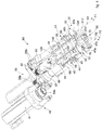
- Embodiments described here concern a device 30 for working blanks, hereafter defined for short as bending device, configured to perform at least some work operations on a blank 100, including flexing and/or bending panels or flaps of the blank 100.
- the bending device 30 can be used in an apparatus 10 according to the present description.
- flexing in the present description means a process of flexing the material with which the blank is made, by pre-bending in correspondence with suitable pre-weakened bending lines present on the blanks 100, to reduce the residual elastic return of the material once definitively bent.
- the bending device 30 can perform at least two distinct operations.
- the bending device 30 can be configured to flex the blank 100 along the longitudinal bending lines 120' and along the transverse bending line 115' which is between the first smaller upper panel 122' and the second smaller upper panel 124', and to bend the first smaller upper panel 122' against the second smaller upper panel 124', for gluing purposes.
- the bending device 30 includes a single-body structure provided with:
- the first flexing members 32 are configured to flex the blank 100 along the transverse bending line 115' that joins the first smaller upper panel 122' and the second smaller upper panel 124'.
- the blank 100 is disposed between the two first flexing members 32 and can be kept in this operating position thanks to a suction retaining member, such as a sucker, which can be present on a holding head of an apparatus for working blanks as described in detail hereafter.
- first flexing or pre-bending members 32 and the complete bending member 52 allows to obtain a straight, precise and well-defined transverse bending line 115'.
- the first flexing or pre-bending members 32 and the second flexing or pre-bending members 34 can be driven by a single command, thus exploiting the drive of the first flexing or pre-bending members 32 to activate the second flexing or pre-bending members 34 as well. Consequently, advantageously with a single command and movement, it is possible to flex or pre-bend the transverse bending line 115' and also the longitudinal bending lines 120'.
- the first flexing members 32 and the second flexing members 34 are mounted on rotation shafts 36, 38 disposed parallel and distanced with respect to each other.
- One rotation shaft 36 is therefore provided with a first flexing member 32 and a second flexing member 34
- the other rotation shaft 38 is provided with the other first flexing member 32 and with the other second flexing member 34.
- the first flexing members 32 are positioned at the free ends of the rotation shafts 36, 38, while the second flexing members 34 are disposed along the rotation shafts 36, 38 in an intermediate position.
- the rotation shafts 36, 38 are disposed parallel to each other, distanced by a space with an amplitude coordinated with the length of the short side of the intermediate main 112' and lower 114' panels of the blank 100.
- the rotation shafts 36, 38 can be driven by one or more actuation elements 40 and made to rotate around respective axes of rotation X1 and X2, respectively in the direction of the arrows F1 and F2 (see fig. 9 ).
- the actuation element 40 can comprise a drive member 41, provided with a drive shaft and configured to make at least one rotation shaft 36, 38 rotate, which can be made to function by an energy source, for example an electric current, a hydraulic fluid pressure or a pneumatic pressure.
- the drive member 41 can be in particular a motor provided with an intrinsically rotary movement actuator or configured to convert a linear movement into a circular movement.
- the conversion can be carried out commonly through types of conversion mechanisms chosen in a group consisting of: screw actuators, such as actuators of the screw jack type, ball screw actuators and roll screw actuators, or wheel and axle, for example with drums, gears, pulleys or shafts, actuators like a lifting cable, a winch, a pinion and rack unit, a chain transmission, belt transmission, possibly toothed, actuators with a rigid chain and rigid belt, or rigid belts, possibly toothed.
- screw actuators such as actuators of the screw jack type, ball screw actuators and roll screw actuators, or wheel and axle, for example with drums, gears, pulleys or shafts, actuators like a lifting cable, a winch, a pinion and rack unit, a chain transmission, belt transmission, possibly toothed, actuators with a rigid chain and rigid belt, or rigid belts, possibly toothed.
- the actuation element 40 can include a drive member 41 chosen from a group consisting of an electric motor, pneumatic motor, hydraulic piston or piezoelectric actuator.
- the actuation element 40 as used in association with embodiments described here, can be a movement actuator that, in possible implementations, can be configured to transfer the motion to, and make rotate, both the rotation shafts 36, 38.
- the motion can commonly be transferred by types of motion transmission mechanisms.
- the motion can be transferred from the drive member 41 to the rotation shafts 36, 38 by means of a motion transmission mechanism 35.
- the motion transmission mechanism 35 can comprise a toothed belt 37.
- the toothed belt 37 is typically wound around toothed pulleys, with which a toothed drive pulley 39a can be provided, keyed to the drive shaft of the drive member 41, and a plurality of toothed driven pulleys 39b.
- two toothed driven pulleys 39b are provided for example, respectively connected to the rotation shafts 36, 38.
- the toothed belt 37 made to rotate by the toothed drive pulley 39a, can be configured to transfer the circular motion from the drive member 41 to the toothed driven pulleys 39b connected to the rotation shafts 36, 38.
- the toothed belt 37 is wound on the toothed drive pulley 39a and the toothed driven pulley 39b of the rotation shaft 36 with its internal surface, while it is wound on the toothed driven pulley 39b of the rotation shaft 38 with its external surface. In this way, the direction of rotation of the rotation shafts 36, 38 is reciprocally opposite.
- the toothed belt 37 engages the toothed driven pulleys 39b of the rotation shafts 36, 38, drawing them into counter-rotation, so as to transmit simultaneously the rotation supplied by the drive member 41 to the two rotation shafts 36, 38, as we said, making them rotate in the opposite direction.
- first flexing members 32 and the second flexing members 34 can be made in a single body, that is, they can be integrated. In this way it is possible to drive the first flexing members 32 and the second flexing members 34 with a single command and movement.
- first flexing members 32 and the second flexing members 34 can be made as different components.
- first flexing members 32 and the second flexing members 34 can be connected operatively to be driven by a single command and movement.
- the first flexing members 32 can each comprise a saber-shaped transverse portion 42, normally facing toward the internal space comprised between the two rotation shafts 36, 38, in order to act on the front part of the blank 100 where there is the first smaller upper panel 122'.
- the saber-shaped transverse portion 42 can be formed by a shaped plate that has a lobe 42a, rotatably constrained to the respective rotation shaft 36, 38, and a protruding curved tooth 42b.
- the two saber-shaped transverse portions 42 extend toward the inside by a length sufficient to reach the first smaller upper panel 122' of the blank 100, so as to be able to act against the first smaller upper panel 122' of the blank 100. This action determines a thrust of the two saber-shaped transverse portions 42, in particular of the curved teeth 42b, on one side and the other of the first smaller upper panel 122', bending it by about 90° with respect to the lying plane of the blank 100.
- the axes of rotation X1 and X2 are perpendicular to the two saber-shaped transverse portions 42.
- the saber-shaped transverse portions 42 press on the first smaller upper panel 122', thus flexing the transverse bending line 115' between the first smaller upper panel 122' and the second smaller upper panel 124'.
- the second flexing members 34 can each include a longitudinal blade portion 44, able to act at least on the longitudinal lateral panels 118', 119', and possibly also on the upper lateral flaps 130' of the blank 100, flexing the respective longitudinal bending lines 120', rotatably connected to each rotation shaft 36, 38.
- the longitudinal blade portions 44 have a length mating with the length of the longitudinal bending lines 120' of the blank 100.
- the longitudinal blade portions 44 can be connected to the respective rotation shafts 36, 38 for example by attachment members 43, which can be the releasable and/or adjustable type.
- the axes of rotation X1 and X2 are parallel to the two longitudinal blade portions 44.
- Grooves 45 can be provided on the rotation shafts 36, 38, configured to cooperate with the attachment members 43, so as to allow the second flexing members 34 to slide along a segment of the rotation shafts 36, 38. In this way, the second flexing members 34 can be positioned on each occasion in the most suitable position with respect to the characteristics of the blank 100 to be worked.
- the longitudinal blade portions 44 can be configured for example as a bent plate, for example at a right angle, in its longitudinal direction, having the bent parts configured to press at least on the longitudinal lateral panels 118', 119' and possibly also on the upper lateral flaps 130', in order to pre-bend them along the longitudinal bending lines 120'.
- the longitudinal blade portions 44 can be a single blade that extends for the length of the blank 100, or they can consist of several longitudinal blade portions, positioned in correspondence with at least the longitudinal lateral panels 118', 119' and possibly also with the upper lateral flaps 130'.
- the longitudinal blade portions 44 during the rotation in the direction of the arrows F1, F2, press at least on the first and second longitudinal lateral panels 118', 119' and possibly also on the upper lateral flaps 130', pre-bending them transversely, for example by an angle of 90°, with respect to the intermediate main panel 112' and lower main panel 114' ( fig. 9 ). Due to the elastic return of the material, the final pre-bending angle can be less than 90°.
- the longitudinal blade portions 44 can be configured to act, as described above, also on the intermediate lateral flaps 132' 134' and lower lateral flaps 136'.
- the saber-shaped transverse portions 42 can be integrated in a single body with the respective longitudinal blade portions 44, or they can be made as different components, advantageously connected operatively.
- the first flexing members 32 and the second flexing members 34 can be operatively connected and driven in rotation by 360° around respective operating axes by the respective rotation shafts 36, 38, so that, with a complete and single rotation by a round angle (360°), it is possible to intervene both on the first smaller upper panel 122' and also on the first and second longitudinal lateral panels 118', 119' and possibly also on the lateral flaps 130', 132', 134', 136', obtaining the pre-bending or flexing of the respective transverse bending line 115' and longitudinal bending lines 120'. Furthermore, it is also possible to intervene with the complete bending member 52 to further bend the first smaller upper panel 122', thus bending it by 180° overall. Therefore, advantageously with a command of a single continuous rotation of 360°, it is possible to obtain the desired pre-bending or flexing operations and, subsequently, to provide also the complete bending of the first smaller upper panel 122'.
- the reciprocal angular position on the respective rotation shafts 36, 38 of the first flexing members 32 and of the second flexing members 34 can be such that, with the rotation of the rotation shafts 36, 38 by the desired operative angle of 360°, the first flexing members 32 and second flexing members 34 begin to interfere with the respective parts of the blank 100 to be pre-bent.
- the reciprocal angular position on the respective rotation shafts 36, 38 of the first flexing members 32 and the second flexing members 34 can be angularly offset along the round angle (360°), so as to pre-bend the various components in different angular phases, and successive in time, for example first the first smaller upper panel 122' and then the longitudinal lateral panels 118', 119' and possibly the lateral flaps 130', 132', 134', 136' or vice versa, or again it is possible to make the different pre-bending operations at partly overlapping times.
- first the first flexing members 32 can intervene, which by means of the saber-shaped transverse portions 42 pre-bend the first smaller upper panel 122', and subsequently the second flexing members 34 can intervene, which by means of the longitudinal blade portions 44 pre-bend the longitudinal lateral panels 118', 119' and possibly the lateral flaps 130', 132', 134', 136', or vice versa.
- the reciprocal angular position on the respective rotation shafts 36, 38 of the first flexing members 32 and the second flexing members 34 is in phase, so as to pre-bend simultaneously the first smaller upper panel 122' and the longitudinal lateral panels 118', 119' and possibly the lateral flaps 130', 132', 134', 136'.
- a blank contrast plate 46 is provided, on which the blank 100 is intended to be rested and temporarily abutted, so as to contrast the pressing action of the flexing members 32, 34 and advantageously to facilitate and optimize the flexing operations, also functioning as a ridge along the edges.
- the blank contrast plate 46 can therefore be used to flex the blank 100 along the bending lines 120', 115' respectively.
- the blank contrast plate 46 is configured mobile to selectively function as an abutment for the blank.
- the blank contrast plate 46 can have a substantially rectangular shape, configured to adapt to the area of the blank 100 comprised between the longitudinal lateral panels 118', 119', the lateral flaps 130', 132', 134', 136' and the first smaller upper panel 122'.
- the bending device 30 can be provided with a support element 48 to which the blank contrast plate 46 is connected. Screws 50 can be provided, or analogous attachment members, to connect the blank contrast plate 46 to the support element 48 by any suitable mean.
- the bending device 30 can be provided with support brackets 56 to which, for example by pins 57, the support element 48 can be rotatably connected.
- the bending device 30 also comprises the complete bending member 52, configured to bend further, i.e. to completely bend, thus obtaining an overall rotation of 180°, the first smaller upper panel 122', taking it into contact with the second smaller upper panel 124' for gluing.
- This bending system allows to make straight, precise and well-defined transverse bending lines 115'.
- the complete bending member 52 can be provided with a mobile tooth portion 54 which, during use, faces toward the blank 100.
- the tooth portion 54 can have a flat end, configured to contact and press on the first smaller upper panel 122', bending it by 180°, i.e., completely bending it against the second smaller upper panel 124'.
- the complete bending member 52 is configured mobile, in coordination with the flexing members 32, 34, to act on the first smaller upper panel 122' after this has been pre-bent by the first flexing members 32.
- the movement of the complete bending member 52 is configured to cause interference between the tooth portion 54 and the first smaller upper panel 122': the latter is already pre-bent transversely by about 90° and is thus intercepted and thrust by the tooth portion 54 that bends it further, by about another 90°, with respect to the blank 100 and thus bends it further against the second smaller upper panel 124', bending it by about 180° in all.
- a glue can be present on the first smaller upper panel 122', for example generally the type with a rapid gluing effect, which can be delivered by a glue delivery device provided in association with the apparatus for working blanks according to the present description, before the blank is supplied to the bending device 30. Consequently, when the first smaller upper panel 122' comes into contact with the second smaller upper panel 124', it remains adherent to it thanks to the previously delivered glue.
- the complete bending member 52 can move between an inactive position, in which it is not in contact with the first smaller upper panel 122', and an operating positon in which it interferes with the first smaller upper panel 122', bending it further against the second smaller upper panel 124'.
- the bending device 30 comprises a movement unit 58 configured to move, in a synchronous and coordinated manner, the support element 48, and hence the blank contrast plate 46 connected thereto, and the complete bending member 52.
- the movement unit 58 is configured to determine an alternate motion of the support element 48 and of the blank contrast plate 46 connected thereto.
- the movement unit 58 is configured to determine a movement to bring the blank contrast plate 46 nearer to the blank 100, to act as an abutment, and at the same time to distance the complete bending member 52. In this way, the first and second flexing members 32 and 34 can intervene.
- the movement unit 58 is configured to determine a distancing movement of the blank contrast plate 46 from the blank 100, since no abutment is necessary any longer, and at the same time to bring the complete bending member 52 nearer, which can thus further bend the first smaller upper panel 122'.
- the movement unit 58 can comprise a toothed driven pulley 39b, around which a part of the external surface of the toothed belt 37 is wound.
- the toothed driven pulley 39b is connected to a rotation shaft 62.
- the movement unit 58 can also comprise a connecting rod-handle mechanism 64, driven by the rotation shaft 62 coupled to the toothed driven pulley 39b.
- the connecting rod-handle mechanism 64 comprises a handle element 66 connected to the rotation shaft 62 made to rotate by the toothed driven pulley 39b.
- the rotation shaft 62 makes the handle element 66 rotate around its axis of rotation Z in the direction indicated by arrow Q in figs. 7 and 8 .
- the connecting rod-handle mechanism 64 also includes a connecting rod element 68 connected to the handle element 66 and configured to make a rectilinear motion, in a direction perpendicular to the direction in which the blank 100 is aligned.
- the connecting rod element 68 can be connected to the handle element 66 by a rod 70, pivoted to a handle pin 72 positioned eccentrically with respect to the axis Z, to convert the circular motion of the handle element 66 into a rectilinear motion of the connecting rod element 68.
- the connecting rod element 68 is connected to the support element 48.
- the support element 48 preferably has an aperture 68a to rotatably house part of the connecting rod element 68.
- the connecting rod element 68 during its rectilinear motion, is configured to cause the translation of the support element 48 and the blank contrast plate 46 connected to it from an adjacent position, for example essentially parallel to that of the blank 100, to a position distanced from it, for example by means of a rotation that can cause the inclination of the support element 48 and the blank contrast plate 46 connected to it by an angle ⁇ , which can be comprised for example between 15° and 60°, for example between 30° and 45°, or between 15° and 30°, or again between 45° and 60°, depending on needs.
- angle ⁇ which can be comprised for example between 15° and 60°, for example between 30° and 45°, or between 15° and 30°, or again between 45° and 60°, depending on needs.
- the movement unit 58 also comprises a motion transfer unit 74, configured to move at least the complete bending member 52 that further bends the first smaller upper panel 122' as described above.
- the motion transfer unit 74 is configured to transfer the alternate movement of the support element 48 and the blank contrast plate 46 to the complete bending member 52.
- support element 48 and blank contrast plate 46 are moved in phase opposition from and toward the blank 100, with respect to the movement of the complete bending member 52.
- the complete bending member 52 is distanced from the blank 100, and vice versa.
- the motion transfer unit 74 can comprise a return rod 76, with one end pivoted to the support element 48 and an opposite end pivoted to a lever element 78. In this way, the return rod 76, driven by the movement of the support element 48, in turn drives the lever element 78, which takes the tooth portion 54 into contact with the front lid wall 124.
- a pair of opposite support brackets 79 can be provided, to which the lever element 78 is pivoted by pins 80.
- the lever element 78 can itself define the complete bending member 52 (see figs. 7 and 8 for example), while according to other variants the lever element 78 can be distinct from the complete bending member 52 and connected thereto by means of connection elements, such as an arm or a connection rod, not shown here.
- the lever element 78 can be an angled lever, or L-lever, which can have a shape with two sides 78a, 78b, positioned inclined with respect to each other by an angle ⁇ .
- Angle ⁇ can be chosen for example between 80° and 120°, for example between 90° and 110°, or between 80° and 90°, or again between 110° and 120°, according to needs.
- the bending device 30 is therefore able to perform, in succession after each other, different work operations on the blank 100, in particular flexing/pre-bending and bending proper, in the case of the first smaller upper panel 122'.
- first and second flexing members 32, 34 cooperating with the blank contrast plate 46, act on the blank 100, flexing it and pre-bending it along the longitudinal bending lines 120' and the transverse bending line 115' between the first 122' and second 124' smaller upper panels.
- the movement unit 58 moves the blank contrast plate 46, distancing it from the blank 100 and, at the same time, takes the tooth portion 54 of the complete bending member 52 into contact with the first smaller upper panel 122', so as to further bend it against the second smaller upper panel 124'.
- the actuation element 40 which drives the rotation shafts 36, 38 connected to the toothed driven pulleys 39b of the first and second flexing members 32, 34 and the rotation shaft 62 connected to the toothed driven pulley 39b which determines the alternate movement of the blank contrast plate 46 and the complete bending member 52, can advantageously be controlled by software, to synchronize the reciprocal movement of the first and second flexing members 32, 34, the blank contrast plate 46 and the complete bending member 52, to perform the operations described above sequentially.
- the bending device 30 can be used in an apparatus 10 for working blanks according to the present description.
- the apparatus 10 comprises a blank transfer wheel 12 provided with an entrance station 14 and an exit station 16, between which a predefined transfer path P is defined.
- the blank transfer wheel 12 also comprises a flexing and bending station 18 installed in an intermediate position between the entrance station 14 and the exit station 16.
- the blank transfer wheel 12 is configured to rotate with an intermittent motion, i.e. step-wise, around an axis of rotation Y, in the direction indicated by arrow R in fig. 6 , to move a plurality of holding heads 20 along the predefined transfer path P.
- the transfer path P can affect, for example, an angular sector of 240° of the blank transfer wheel 12, where an angle 0° is taken as reference in correspondence with the entrance station 14.
- the entrance station 14 and the exit station 16 are in any other reciprocal angular position on the blank transfer wheel 12, and the transfer path P can affect for example a different angular sector, for example less than 240°, for example from 180° to 240°, or greater, for example from 240° to 270°, or other angular positions, according to needs.
- the step-wise movement of the blank transfer wheel 12 can provide that the rotation steps are coordinated with angular sectors affected by the specific work stations of the apparatus 10.
- each holding head 20 of the blank transfer wheel 12 can comprise retaining members 24, configured to retain a blank 100 and transport it stably from the entrance station 14 to the exit station 16.
- retaining members 24 can be retaining members 24 that operate under suction, for example sucker members.
- Embodiments described here thus provide to move the blanks 100 in order to make, along the transfer path P, semi-worked pieces from which the packets 102 will then be formed.
- the apparatus 10 is configured to make stops at each step in correspondence with a specific station, to perform one or more operations on the blank.
- the entrance station 14 is associated with a blank feeding store 22, disposed outside the blank transfer wheel 12, in which a plurality of blanks 100 are stored.
- the blanks 100 are taken from the blank feeding store 22 and fed to the holding heads 20 which pass through the entrance station 14 on each occasion and stay there temporarily to receive a respective blank 100.
- the blank 100 can be fed with its face on which there are normally writings, graphical signs, decorative patterns, logos or other printing, facing toward the holding head 20, i.e. toward the inside of the blank transfer wheel 12, while the opposite face, which has no such printed elements, faces toward the outside.
- the apparatus 10 includes devices to hold and/or deliver blanks 92, provided at the entrance station 14 and exit station 16.
- the devices to hold and/or deliver blanks 92 can be provided to pick up the blanks 100, one at a time, from the blank feeding store 22 and to feed them to the holding heads 20 in the entrance station 14, and to pick up the blanks from the holding heads 20 at the exit station 16, in order to deliver them to further operating units downstream of the apparatus 10.
- Each device to hold and/or deliver blanks 92 can comprise a mechanical arm 94, which moves in a constrained circular motion along an arc of a circle and which takes a free end 96 into correspondence with respectively the entrance station 14 and/or the exit station 16.
- the corresponding device to hold and/or deliver blanks 92 supplies to the holding head 20 a blank 100 taken from the blank feeding store 22, while at the exit station 16, the corresponding device to hold and/or deliver blanks 92 picks up the blank 100 from the holding head 20 and delivers it outside the blank transfer wheel 12, for example to a subsequent transfer wheel to perform the subsequent work on the blank and further make-up operations that will lead to the formation of the complete packet 102.
- the holding head 20 transfers the blank 100 to the flexing and bending station 18 to flex the longitudinal bending lines 120', the transverse bending line 115' between the first smaller upper panel 122' and the second smaller upper panel 124', and to bend definitively the first smaller upper panel 122' against the second smaller upper panel 124'.
- first glue dispensing station 26 provided with glue deliverers 28.
- the glue deliverers 28 are configured to deliver glue onto the first smaller upper panel 122' of the blank 100, typically on the face that has no printed elements, which faces toward the outside of the holding head 20 and hence of the blank transfer wheel 12.
- the glue can be delivered by the glue deliverers 28 during the rotation of the blank transfer wheel 12, in the travel between the entrance station 14 and the flexing and bending station 18, without needing to stop, i.e. during an advance step of the blank transfer wheel 12.
- the glue can be delivered by the glue deliverers 28 on the fly, for example exploiting the instants of acceleration and deceleration of the blank transfer wheel 12 arriving at and leaving the work stations.
- the glue deliverers 28 are positioned upstream of the flexing and bending station 18 and can deliver the glue onto the first smaller upper panel 122' in particular during the deceleration of the blank transfer wheel 12, before a holding head 20 is positioned in the flexing and bending station 18.
- glue deliverers 28 are jet glue deliverers, nozzles, pistols, syringes or similar glue delivery members.
- the flexing and bending station 18 comprises a bending device 30 to work the blanks according to embodiments described here.
- the bending device 30 is provided to flex and subsequently to completely bend the first smaller upper panel 122' on the second smaller upper panel 124', and to flex the first longitudinal lateral panels 118', and the second longitudinal lateral panels 119' and possibly the lateral flaps 130', 132', 134', 136'.
- the flexing and bending station 18 comprises exclusively the bending device 30.
- the blank 100 therefore has the longitudinal lateral panels 118', 119' and possibly the lateral flaps 130', 132', 134', 136' pre-bent, partly inclined toward the outside with respect to the blank transfer wheel 12, and the first smaller upper panel 122' is located adjacent against the second smaller upper panel 124', with the glue between them.
- the apparatus 10 also comprises a pressing station 82, configured to consolidate the gluing of the first smaller upper panel 122' to the second smaller upper panel 124'.
- the pressing station 82 is downstream of the flexing and bending station 18 along the transfer path P.
- the pressing station 82 comprises pressing members 84, 86, for example rollers, or press elements, configured to act in compression simultaneously on the opposite faces of the blank 100.
- the pressing members 84, 86 are configured to exert a pressure on the first smaller upper panel 122' on one side and on the second smaller upper panel 124' on the other side, pressing them against each other, so as to consolidate the gluing between them.
- the pressing members 84, 86 can be rolls, disposed so as to rotate around the respective axes of rotation in an opposite direction to each other, in the direction indicated by arrows G1, G2 respectively.
- the apparatus 10 also comprises another glue dispensing station 88, configured to deliver glue at least onto the second longitudinal lateral panels 119', so that they can be glued overlapping the longitudinal lateral panels 118'.
- the glue dispensing station 88 is downstream of the pressing station 82 along the transfer path P.
- the glue dispensing station 88 comprises one or more glue deliverers 90 configured to deliver jets of glue, for example at different points, i.e. to deliver points of glue or, in combination, to deliver glue in a linear distribution, in strips, or to nebulize it.
- the type of glue that can be delivered can be hot glue and/or cold glue.
- the glue deliverers 90 can be provided to deliver all the same type of glue or different types of glue.
- one or more glue deliverers 90 can be provided to deliver glue that immediately gives a certain grip, albeit with less stability over time, while another one or more glue deliverers 90 can be provided to deliver another type of glue which instead guarantees stability and resistance over time.
- glue deliverers 90 are jet glue deliverers, nozzles, pistols, syringes or similar glue delivery members.
- the glue dispensing station 88 comprises a plurality of glue deliverers 90, disposed in series or arrays, in a vertical disposition, perpendicular to the transfer path P.
- the glue deliverers 90 can be fixed glue deliverers 90, configured to deliver glue on the second longitudinal lateral panels 119' of the blanks 100 during the deceleration and acceleration of the blank transfer wheel 12 approaching the glue dispensing station 88 or away from it.
- the glue deliverers 90 deliver the glue on the second longitudinal lateral panels 119' disposed on the right in fig. 3 during the deceleration of the holding head 20 approaching the glue dispensing station 88.
- the glue deliverers 90 do not deliver glue.
- the glue deliverers 90 deliver the glue onto the second longitudinal lateral panels 119' disposed on the left in fig. 3 during the acceleration of the holding head 20 exiting from the glue dispensing station 88.
Landscapes
- Engineering & Computer Science (AREA)
- Mechanical Engineering (AREA)
- Making Paper Articles (AREA)
Priority Applications (1)
| Application Number | Priority Date | Filing Date | Title |
|---|---|---|---|
| PL16712515T PL3265387T3 (pl) | 2015-02-26 | 2016-02-26 | Narzędzie, sposób i urządzenie do obróbki wykrojów do wytwarzania sztywnych opakowań na wyroby do palenia |
Applications Claiming Priority (2)
| Application Number | Priority Date | Filing Date | Title |
|---|---|---|---|
| ITMI20150292 | 2015-02-26 | ||
| PCT/IB2016/051064 WO2016135687A1 (en) | 2015-02-26 | 2016-02-26 | Apparatus, method and device for working blanks to make rigid packets for smoking articles |
Publications (2)
| Publication Number | Publication Date |
|---|---|
| EP3265387A1 EP3265387A1 (en) | 2018-01-10 |
| EP3265387B1 true EP3265387B1 (en) | 2019-06-05 |
Family
ID=53016673
Family Applications (1)
| Application Number | Title | Priority Date | Filing Date |
|---|---|---|---|
| EP16712515.2A Active EP3265387B1 (en) | 2015-02-26 | 2016-02-26 | Apparatus, method and device for working blanks to make rigid packets for smoking articles |
Country Status (3)
| Country | Link |
|---|---|
| EP (1) | EP3265387B1 (pl) |
| PL (1) | PL3265387T3 (pl) |
| WO (1) | WO2016135687A1 (pl) |
Families Citing this family (1)
| Publication number | Priority date | Publication date | Assignee | Title |
|---|---|---|---|---|
| PL247669B1 (pl) * | 2022-12-20 | 2025-08-18 | Protim Spolka Z Ograniczona Odpowiedzialnoscia | Sposób formowania opakowania kartonowego z pojedynczego arkusza tektury falistej oraz układ do formowania opakowania kartonowego z pojedynczego arkusza tektury falistej |
Family Cites Families (4)
| Publication number | Priority date | Publication date | Assignee | Title |
|---|---|---|---|---|
| IT1069471B (it) * | 1976-05-06 | 1985-03-25 | Gd Spa | Dispositivo di piegatura di materiale in foglio..particolarmente di sbozzati o fustellati di cartoncino o simili da alimentare ad una macchina condizionatrice di sigarette in pacchetti del tipo con coperchio incernierato hinged lid |
| IT1294187B1 (it) * | 1997-09-04 | 1999-03-22 | Gd Spa | Metodo per la piegatura di sbozzati di incarto. |
| ITBO20070366A1 (it) * | 2007-05-22 | 2008-11-23 | Gd Spa | Metodo e sistema per la snervatura di uno sbozzato piano destinato alla realizzazione di un incarto rigido, |
| ITBO20130427A1 (it) * | 2013-08-01 | 2015-02-02 | Gd Spa | Macchina e metodo di confezionamento di pacchetti di sigarette. |
-
2016
- 2016-02-26 PL PL16712515T patent/PL3265387T3/pl unknown
- 2016-02-26 EP EP16712515.2A patent/EP3265387B1/en active Active
- 2016-02-26 WO PCT/IB2016/051064 patent/WO2016135687A1/en not_active Ceased
Non-Patent Citations (1)
| Title |
|---|
| None * |
Also Published As
| Publication number | Publication date |
|---|---|
| EP3265387A1 (en) | 2018-01-10 |
| WO2016135687A1 (en) | 2016-09-01 |
| PL3265387T3 (pl) | 2019-10-31 |
Similar Documents
| Publication | Publication Date | Title |
|---|---|---|
| EP2829483B1 (en) | Packing unit and method for folding a blank on a packing machine | |
| US2441445A (en) | Method and machine for forming and filling reclosable cartons | |
| JP5657931B2 (ja) | 折畳みチラシを形成し付与するための方法及び装置 | |
| ITBO960589A1 (it) | Metodo di incarto per pacchetti rigidi di sigarette | |
| US20150336696A1 (en) | Packing machine and packing method for producing an inner container of a slide-open package of tobacco articles and with a hinged lid | |
| US4834696A (en) | Folding of paperboard sheets and the like | |
| ITBO20120700A1 (it) | Macchina impacchettatrice e metodo di incarto per realizzare un contenitore interno di una confezione di articoli da fumo con apertura a scorrimento. | |
| US5674542A (en) | Apparatus for the production of blanks for collars in hinge-lid packs with rounded or polygonal longitudinal edges | |
| EP3265387B1 (en) | Apparatus, method and device for working blanks to make rigid packets for smoking articles | |
| US10017284B2 (en) | Packing method and packing machine for producing a slide-open package of tobacco articles with a hinged lid | |
| EP4046921B1 (en) | Packer machine and wrapping method to produce a pack of smoking articles | |
| CN216471319U (zh) | 全自动皮壳机 | |
| EP3439861B1 (en) | A cornet bending machine with independent motion control system from mechanics | |
| EP2279955B1 (en) | A method and equipment for applying labels to products | |
| EP3172133B1 (en) | Apparatus and method for making up packets for smoking articles | |
| EP2935013B1 (en) | Packing machine and packing method for producing an inner container by folding an inner blank about a wrapped group of tobacco articles | |
| EP4288278A1 (en) | Assembly and method for the automated folding of corners of a box | |
| CN113954548A (zh) | 全自动皮壳机 | |
| US1902079A (en) | Box wrapping machine | |
| WO2015015409A1 (en) | Packaging machine and method for packing cigarettes. | |
| JP2005162329A (ja) | 包装装置 | |
| ITTO20100409A1 (it) | Macchina incassatrice e relativo metodo di incassatura | |
| CH703085B1 (it) | Procedimento e dispositivo per la snervatura di uno sbozzato piano destinato alla realizzazione di un incarto rigido. | |
| EP1757521A1 (en) | A machine for packing products in cases | |
| US705206A (en) | Box folding and pasting machine. |
Legal Events
| Date | Code | Title | Description |
|---|---|---|---|
| STAA | Information on the status of an ep patent application or granted ep patent |
Free format text: STATUS: THE INTERNATIONAL PUBLICATION HAS BEEN MADE |
|
| PUAI | Public reference made under article 153(3) epc to a published international application that has entered the european phase |
Free format text: ORIGINAL CODE: 0009012 |
|
| STAA | Information on the status of an ep patent application or granted ep patent |
Free format text: STATUS: REQUEST FOR EXAMINATION WAS MADE |
|
| 17P | Request for examination filed |
Effective date: 20170825 |
|
| AK | Designated contracting states |
Kind code of ref document: A1 Designated state(s): AL AT BE BG CH CY CZ DE DK EE ES FI FR GB GR HR HU IE IS IT LI LT LU LV MC MK MT NL NO PL PT RO RS SE SI SK SM TR |
|
| AX | Request for extension of the european patent |
Extension state: BA ME |
|
| DAV | Request for validation of the european patent (deleted) | ||
| DAX | Request for extension of the european patent (deleted) | ||
| GRAP | Despatch of communication of intention to grant a patent |
Free format text: ORIGINAL CODE: EPIDOSNIGR1 |
|
| STAA | Information on the status of an ep patent application or granted ep patent |
Free format text: STATUS: GRANT OF PATENT IS INTENDED |
|
| INTG | Intention to grant announced |
Effective date: 20190129 |
|
| GRAS | Grant fee paid |
Free format text: ORIGINAL CODE: EPIDOSNIGR3 |
|
| GRAA | (expected) grant |
Free format text: ORIGINAL CODE: 0009210 |
|
| STAA | Information on the status of an ep patent application or granted ep patent |
Free format text: STATUS: THE PATENT HAS BEEN GRANTED |
|
| AK | Designated contracting states |
Kind code of ref document: B1 Designated state(s): AL AT BE BG CH CY CZ DE DK EE ES FI FR GB GR HR HU IE IS IT LI LT LU LV MC MK MT NL NO PL PT RO RS SE SI SK SM TR |
|
| REG | Reference to a national code |
Ref country code: GB Ref legal event code: FG4D |
|
| REG | Reference to a national code |
Ref country code: CH Ref legal event code: EP |
|
| REG | Reference to a national code |
Ref country code: AT Ref legal event code: REF Ref document number: 1139761 Country of ref document: AT Kind code of ref document: T Effective date: 20190615 |
|
| REG | Reference to a national code |
Ref country code: IE Ref legal event code: FG4D |
|
| REG | Reference to a national code |
Ref country code: DE Ref legal event code: R096 Ref document number: 602016014794 Country of ref document: DE |
|
| REG | Reference to a national code |
Ref country code: NL Ref legal event code: MP Effective date: 20190605 |
|
| REG | Reference to a national code |
Ref country code: LT Ref legal event code: MG4D |
|
| PG25 | Lapsed in a contracting state [announced via postgrant information from national office to epo] |
Ref country code: ES Free format text: LAPSE BECAUSE OF FAILURE TO SUBMIT A TRANSLATION OF THE DESCRIPTION OR TO PAY THE FEE WITHIN THE PRESCRIBED TIME-LIMIT Effective date: 20190605 Ref country code: SE Free format text: LAPSE BECAUSE OF FAILURE TO SUBMIT A TRANSLATION OF THE DESCRIPTION OR TO PAY THE FEE WITHIN THE PRESCRIBED TIME-LIMIT Effective date: 20190605 Ref country code: AL Free format text: LAPSE BECAUSE OF FAILURE TO SUBMIT A TRANSLATION OF THE DESCRIPTION OR TO PAY THE FEE WITHIN THE PRESCRIBED TIME-LIMIT Effective date: 20190605 Ref country code: LT Free format text: LAPSE BECAUSE OF FAILURE TO SUBMIT A TRANSLATION OF THE DESCRIPTION OR TO PAY THE FEE WITHIN THE PRESCRIBED TIME-LIMIT Effective date: 20190605 Ref country code: HR Free format text: LAPSE BECAUSE OF FAILURE TO SUBMIT A TRANSLATION OF THE DESCRIPTION OR TO PAY THE FEE WITHIN THE PRESCRIBED TIME-LIMIT Effective date: 20190605 Ref country code: FI Free format text: LAPSE BECAUSE OF FAILURE TO SUBMIT A TRANSLATION OF THE DESCRIPTION OR TO PAY THE FEE WITHIN THE PRESCRIBED TIME-LIMIT Effective date: 20190605 Ref country code: NO Free format text: LAPSE BECAUSE OF FAILURE TO SUBMIT A TRANSLATION OF THE DESCRIPTION OR TO PAY THE FEE WITHIN THE PRESCRIBED TIME-LIMIT Effective date: 20190905 |
|
| PG25 | Lapsed in a contracting state [announced via postgrant information from national office to epo] |
Ref country code: RS Free format text: LAPSE BECAUSE OF FAILURE TO SUBMIT A TRANSLATION OF THE DESCRIPTION OR TO PAY THE FEE WITHIN THE PRESCRIBED TIME-LIMIT Effective date: 20190605 Ref country code: BG Free format text: LAPSE BECAUSE OF FAILURE TO SUBMIT A TRANSLATION OF THE DESCRIPTION OR TO PAY THE FEE WITHIN THE PRESCRIBED TIME-LIMIT Effective date: 20190905 Ref country code: GR Free format text: LAPSE BECAUSE OF FAILURE TO SUBMIT A TRANSLATION OF THE DESCRIPTION OR TO PAY THE FEE WITHIN THE PRESCRIBED TIME-LIMIT Effective date: 20190906 Ref country code: LV Free format text: LAPSE BECAUSE OF FAILURE TO SUBMIT A TRANSLATION OF THE DESCRIPTION OR TO PAY THE FEE WITHIN THE PRESCRIBED TIME-LIMIT Effective date: 20190605 |
|
| RAP2 | Party data changed (patent owner data changed or rights of a patent transferred) |
Owner name: I.M.A. INDUSTRIA MACCHINE AUTOMATICHE S.P.A |
|
| REG | Reference to a national code |
Ref country code: AT Ref legal event code: MK05 Ref document number: 1139761 Country of ref document: AT Kind code of ref document: T Effective date: 20190605 |
|
| PG25 | Lapsed in a contracting state [announced via postgrant information from national office to epo] |
Ref country code: NL Free format text: LAPSE BECAUSE OF FAILURE TO SUBMIT A TRANSLATION OF THE DESCRIPTION OR TO PAY THE FEE WITHIN THE PRESCRIBED TIME-LIMIT Effective date: 20190605 Ref country code: PT Free format text: LAPSE BECAUSE OF FAILURE TO SUBMIT A TRANSLATION OF THE DESCRIPTION OR TO PAY THE FEE WITHIN THE PRESCRIBED TIME-LIMIT Effective date: 20191007 Ref country code: SK Free format text: LAPSE BECAUSE OF FAILURE TO SUBMIT A TRANSLATION OF THE DESCRIPTION OR TO PAY THE FEE WITHIN THE PRESCRIBED TIME-LIMIT Effective date: 20190605 Ref country code: RO Free format text: LAPSE BECAUSE OF FAILURE TO SUBMIT A TRANSLATION OF THE DESCRIPTION OR TO PAY THE FEE WITHIN THE PRESCRIBED TIME-LIMIT Effective date: 20190605 Ref country code: CZ Free format text: LAPSE BECAUSE OF FAILURE TO SUBMIT A TRANSLATION OF THE DESCRIPTION OR TO PAY THE FEE WITHIN THE PRESCRIBED TIME-LIMIT Effective date: 20190605 Ref country code: EE Free format text: LAPSE BECAUSE OF FAILURE TO SUBMIT A TRANSLATION OF THE DESCRIPTION OR TO PAY THE FEE WITHIN THE PRESCRIBED TIME-LIMIT Effective date: 20190605 Ref country code: AT Free format text: LAPSE BECAUSE OF FAILURE TO SUBMIT A TRANSLATION OF THE DESCRIPTION OR TO PAY THE FEE WITHIN THE PRESCRIBED TIME-LIMIT Effective date: 20190605 |
|
| RAP2 | Party data changed (patent owner data changed or rights of a patent transferred) |
Owner name: I.M.A. INDUSTRIA MACCHINE AUTOMATICHE S.P.A. |
|
| PG25 | Lapsed in a contracting state [announced via postgrant information from national office to epo] |
Ref country code: IS Free format text: LAPSE BECAUSE OF FAILURE TO SUBMIT A TRANSLATION OF THE DESCRIPTION OR TO PAY THE FEE WITHIN THE PRESCRIBED TIME-LIMIT Effective date: 20191005 Ref country code: SM Free format text: LAPSE BECAUSE OF FAILURE TO SUBMIT A TRANSLATION OF THE DESCRIPTION OR TO PAY THE FEE WITHIN THE PRESCRIBED TIME-LIMIT Effective date: 20190605 |
|
| REG | Reference to a national code |
Ref country code: DE Ref legal event code: R097 Ref document number: 602016014794 Country of ref document: DE |
|
| PG25 | Lapsed in a contracting state [announced via postgrant information from national office to epo] |
Ref country code: TR Free format text: LAPSE BECAUSE OF FAILURE TO SUBMIT A TRANSLATION OF THE DESCRIPTION OR TO PAY THE FEE WITHIN THE PRESCRIBED TIME-LIMIT Effective date: 20190605 |
|
| PLBE | No opposition filed within time limit |
Free format text: ORIGINAL CODE: 0009261 |
|
| STAA | Information on the status of an ep patent application or granted ep patent |
Free format text: STATUS: NO OPPOSITION FILED WITHIN TIME LIMIT |
|
| PG25 | Lapsed in a contracting state [announced via postgrant information from national office to epo] |
Ref country code: DK Free format text: LAPSE BECAUSE OF FAILURE TO SUBMIT A TRANSLATION OF THE DESCRIPTION OR TO PAY THE FEE WITHIN THE PRESCRIBED TIME-LIMIT Effective date: 20190605 |
|
| 26N | No opposition filed |
Effective date: 20200306 |
|
| PG25 | Lapsed in a contracting state [announced via postgrant information from national office to epo] |
Ref country code: SI Free format text: LAPSE BECAUSE OF FAILURE TO SUBMIT A TRANSLATION OF THE DESCRIPTION OR TO PAY THE FEE WITHIN THE PRESCRIBED TIME-LIMIT Effective date: 20190605 |
|
| REG | Reference to a national code |
Ref country code: CH Ref legal event code: PL |
|
| GBPC | Gb: european patent ceased through non-payment of renewal fee |
Effective date: 20200226 |
|
| REG | Reference to a national code |
Ref country code: BE Ref legal event code: MM Effective date: 20200229 |
|
| PG25 | Lapsed in a contracting state [announced via postgrant information from national office to epo] |
Ref country code: MC Free format text: LAPSE BECAUSE OF FAILURE TO SUBMIT A TRANSLATION OF THE DESCRIPTION OR TO PAY THE FEE WITHIN THE PRESCRIBED TIME-LIMIT Effective date: 20190605 Ref country code: LU Free format text: LAPSE BECAUSE OF NON-PAYMENT OF DUE FEES Effective date: 20200226 |
|
| PG25 | Lapsed in a contracting state [announced via postgrant information from national office to epo] |
Ref country code: CH Free format text: LAPSE BECAUSE OF NON-PAYMENT OF DUE FEES Effective date: 20200229 Ref country code: LI Free format text: LAPSE BECAUSE OF NON-PAYMENT OF DUE FEES Effective date: 20200229 |
|
| PG25 | Lapsed in a contracting state [announced via postgrant information from national office to epo] |
Ref country code: FR Free format text: LAPSE BECAUSE OF NON-PAYMENT OF DUE FEES Effective date: 20200229 Ref country code: IE Free format text: LAPSE BECAUSE OF NON-PAYMENT OF DUE FEES Effective date: 20200226 Ref country code: GB Free format text: LAPSE BECAUSE OF NON-PAYMENT OF DUE FEES Effective date: 20200226 |
|
| PG25 | Lapsed in a contracting state [announced via postgrant information from national office to epo] |
Ref country code: BE Free format text: LAPSE BECAUSE OF NON-PAYMENT OF DUE FEES Effective date: 20200229 |
|
| PG25 | Lapsed in a contracting state [announced via postgrant information from national office to epo] |
Ref country code: MT Free format text: LAPSE BECAUSE OF FAILURE TO SUBMIT A TRANSLATION OF THE DESCRIPTION OR TO PAY THE FEE WITHIN THE PRESCRIBED TIME-LIMIT Effective date: 20190605 Ref country code: CY Free format text: LAPSE BECAUSE OF FAILURE TO SUBMIT A TRANSLATION OF THE DESCRIPTION OR TO PAY THE FEE WITHIN THE PRESCRIBED TIME-LIMIT Effective date: 20190605 |
|
| PG25 | Lapsed in a contracting state [announced via postgrant information from national office to epo] |
Ref country code: MK Free format text: LAPSE BECAUSE OF FAILURE TO SUBMIT A TRANSLATION OF THE DESCRIPTION OR TO PAY THE FEE WITHIN THE PRESCRIBED TIME-LIMIT Effective date: 20190605 |
|
| P01 | Opt-out of the competence of the unified patent court (upc) registered |
Effective date: 20230508 |
|
| PGFP | Annual fee paid to national office [announced via postgrant information from national office to epo] |
Ref country code: DE Payment date: 20250221 Year of fee payment: 10 |
|
| PGFP | Annual fee paid to national office [announced via postgrant information from national office to epo] |
Ref country code: PL Payment date: 20250203 Year of fee payment: 10 |
|
| PGFP | Annual fee paid to national office [announced via postgrant information from national office to epo] |
Ref country code: IT Payment date: 20250212 Year of fee payment: 10 |