EP2829483B1 - Packing unit and method for folding a blank on a packing machine - Google Patents
Packing unit and method for folding a blank on a packing machine Download PDFInfo
- Publication number
- EP2829483B1 EP2829483B1 EP14178239.1A EP14178239A EP2829483B1 EP 2829483 B1 EP2829483 B1 EP 2829483B1 EP 14178239 A EP14178239 A EP 14178239A EP 2829483 B1 EP2829483 B1 EP 2829483B1
- Authority
- EP
- European Patent Office
- Prior art keywords
- packing
- blank
- conveyor
- retaining member
- Prior art date
- Legal status (The legal status is an assumption and is not a legal conclusion. Google has not performed a legal analysis and makes no representation as to the accuracy of the status listed.)
- Active
Links
- 238000012856 packing Methods 0.000 title claims description 147
- 238000000034 method Methods 0.000 title claims description 8
- 238000011144 upstream manufacturing Methods 0.000 claims description 3
- 238000003780 insertion Methods 0.000 description 3
- 230000037431 insertion Effects 0.000 description 3
- 230000001133 acceleration Effects 0.000 description 1
- 238000004026 adhesive bonding Methods 0.000 description 1
- 238000005520 cutting process Methods 0.000 description 1
- 230000000694 effects Effects 0.000 description 1
- 238000004519 manufacturing process Methods 0.000 description 1
- 230000000717 retained effect Effects 0.000 description 1
- 125000006850 spacer group Chemical group 0.000 description 1
Images


Classifications
-
- B—PERFORMING OPERATIONS; TRANSPORTING
- B65—CONVEYING; PACKING; STORING; HANDLING THIN OR FILAMENTARY MATERIAL
- B65B—MACHINES, APPARATUS OR DEVICES FOR, OR METHODS OF, PACKAGING ARTICLES OR MATERIALS; UNPACKING
- B65B43/00—Forming, feeding, opening or setting-up containers or receptacles in association with packaging
- B65B43/24—Breaking creases to facilitate setting-up cartons
-
- B—PERFORMING OPERATIONS; TRANSPORTING
- B65—CONVEYING; PACKING; STORING; HANDLING THIN OR FILAMENTARY MATERIAL
- B65B—MACHINES, APPARATUS OR DEVICES FOR, OR METHODS OF, PACKAGING ARTICLES OR MATERIALS; UNPACKING
- B65B43/00—Forming, feeding, opening or setting-up containers or receptacles in association with packaging
- B65B43/12—Feeding flexible bags or carton blanks in flat or collapsed state; Feeding flat bags connected to form a series or chain
- B65B43/14—Feeding individual bags or carton blanks from piles or magazines
- B65B43/16—Feeding individual bags or carton blanks from piles or magazines by grippers
- B65B43/18—Feeding individual bags or carton blanks from piles or magazines by grippers by suction-operated grippers
- B65B43/185—Feeding individual bags or carton blanks from piles or magazines by grippers by suction-operated grippers specially adapted for carton blanks
-
- B—PERFORMING OPERATIONS; TRANSPORTING
- B65—CONVEYING; PACKING; STORING; HANDLING THIN OR FILAMENTARY MATERIAL
- B65B—MACHINES, APPARATUS OR DEVICES FOR, OR METHODS OF, PACKAGING ARTICLES OR MATERIALS; UNPACKING
- B65B11/00—Wrapping, e.g. partially or wholly enclosing, articles or quantities of material, in strips, sheets or blanks, of flexible material
- B65B11/004—Wrapping, e.g. partially or wholly enclosing, articles or quantities of material, in strips, sheets or blanks, of flexible material in blanks, e.g. sheets precut and creased for folding
-
- B—PERFORMING OPERATIONS; TRANSPORTING
- B65—CONVEYING; PACKING; STORING; HANDLING THIN OR FILAMENTARY MATERIAL
- B65B—MACHINES, APPARATUS OR DEVICES FOR, OR METHODS OF, PACKAGING ARTICLES OR MATERIALS; UNPACKING
- B65B11/00—Wrapping, e.g. partially or wholly enclosing, articles or quantities of material, in strips, sheets or blanks, of flexible material
- B65B11/06—Wrapping articles, or quantities of material, by conveying wrapper and contents in common defined paths
- B65B11/18—Wrapping articles, or quantities of material, by conveying wrapper and contents in common defined paths in two or more straight paths
-
- B—PERFORMING OPERATIONS; TRANSPORTING
- B65—CONVEYING; PACKING; STORING; HANDLING THIN OR FILAMENTARY MATERIAL
- B65B—MACHINES, APPARATUS OR DEVICES FOR, OR METHODS OF, PACKAGING ARTICLES OR MATERIALS; UNPACKING
- B65B43/00—Forming, feeding, opening or setting-up containers or receptacles in association with packaging
- B65B43/12—Feeding flexible bags or carton blanks in flat or collapsed state; Feeding flat bags connected to form a series or chain
- B65B43/14—Feeding individual bags or carton blanks from piles or magazines
- B65B43/16—Feeding individual bags or carton blanks from piles or magazines by grippers
- B65B43/18—Feeding individual bags or carton blanks from piles or magazines by grippers by suction-operated grippers
-
- B—PERFORMING OPERATIONS; TRANSPORTING
- B65—CONVEYING; PACKING; STORING; HANDLING THIN OR FILAMENTARY MATERIAL
- B65B—MACHINES, APPARATUS OR DEVICES FOR, OR METHODS OF, PACKAGING ARTICLES OR MATERIALS; UNPACKING
- B65B43/00—Forming, feeding, opening or setting-up containers or receptacles in association with packaging
- B65B43/26—Opening or distending bags; Opening, erecting, or setting-up boxes, cartons, or carton blanks
- B65B43/265—Opening, erecting or setting-up boxes, cartons or carton blanks
-
- B—PERFORMING OPERATIONS; TRANSPORTING
- B65—CONVEYING; PACKING; STORING; HANDLING THIN OR FILAMENTARY MATERIAL
- B65B—MACHINES, APPARATUS OR DEVICES FOR, OR METHODS OF, PACKAGING ARTICLES OR MATERIALS; UNPACKING
- B65B43/00—Forming, feeding, opening or setting-up containers or receptacles in association with packaging
- B65B43/42—Feeding or positioning bags, boxes, or cartons in the distended, opened, or set-up state; Feeding preformed rigid containers, e.g. tins, capsules, glass tubes, glasses, to the packaging position; Locating containers or receptacles at the filling position; Supporting containers or receptacles during the filling operation
- B65B43/52—Feeding or positioning bags, boxes, or cartons in the distended, opened, or set-up state; Feeding preformed rigid containers, e.g. tins, capsules, glass tubes, glasses, to the packaging position; Locating containers or receptacles at the filling position; Supporting containers or receptacles during the filling operation using roller-ways or endless conveyors
-
- B—PERFORMING OPERATIONS; TRANSPORTING
- B65—CONVEYING; PACKING; STORING; HANDLING THIN OR FILAMENTARY MATERIAL
- B65B—MACHINES, APPARATUS OR DEVICES FOR, OR METHODS OF, PACKAGING ARTICLES OR MATERIALS; UNPACKING
- B65B5/00—Packaging individual articles in containers or receptacles, e.g. bags, sacks, boxes, cartons, cans, jars
- B65B5/02—Machines characterised by incorporation of means for making the containers or receptacles
- B65B5/024—Machines characterised by incorporation of means for making the containers or receptacles for making containers from preformed blanks
-
- B—PERFORMING OPERATIONS; TRANSPORTING
- B65—CONVEYING; PACKING; STORING; HANDLING THIN OR FILAMENTARY MATERIAL
- B65B—MACHINES, APPARATUS OR DEVICES FOR, OR METHODS OF, PACKAGING ARTICLES OR MATERIALS; UNPACKING
- B65B59/00—Arrangements to enable machines to handle articles of different sizes, to produce packages of different sizes, to vary the contents of packages, to handle different types of packaging material, or to give access for cleaning or maintenance purposes
- B65B59/003—Arrangements to enable adjustments related to the packaging material
-
- B—PERFORMING OPERATIONS; TRANSPORTING
- B65—CONVEYING; PACKING; STORING; HANDLING THIN OR FILAMENTARY MATERIAL
- B65B—MACHINES, APPARATUS OR DEVICES FOR, OR METHODS OF, PACKAGING ARTICLES OR MATERIALS; UNPACKING
- B65B59/00—Arrangements to enable machines to handle articles of different sizes, to produce packages of different sizes, to vary the contents of packages, to handle different types of packaging material, or to give access for cleaning or maintenance purposes
- B65B59/005—Adjustable conveying means
-
- B—PERFORMING OPERATIONS; TRANSPORTING
- B31—MAKING ARTICLES OF PAPER, CARDBOARD OR MATERIAL WORKED IN A MANNER ANALOGOUS TO PAPER; WORKING PAPER, CARDBOARD OR MATERIAL WORKED IN A MANNER ANALOGOUS TO PAPER
- B31B—MAKING CONTAINERS OF PAPER, CARDBOARD OR MATERIAL WORKED IN A MANNER ANALOGOUS TO PAPER
- B31B50/00—Making rigid or semi-rigid containers, e.g. boxes or cartons
- B31B50/02—Feeding or positioning sheets, blanks or webs
- B31B50/04—Feeding sheets or blanks
- B31B50/06—Feeding sheets or blanks from stacks
- B31B50/062—Feeding sheets or blanks from stacks from the underside of a magazine
-
- B—PERFORMING OPERATIONS; TRANSPORTING
- B31—MAKING ARTICLES OF PAPER, CARDBOARD OR MATERIAL WORKED IN A MANNER ANALOGOUS TO PAPER; WORKING PAPER, CARDBOARD OR MATERIAL WORKED IN A MANNER ANALOGOUS TO PAPER
- B31B—MAKING CONTAINERS OF PAPER, CARDBOARD OR MATERIAL WORKED IN A MANNER ANALOGOUS TO PAPER
- B31B50/00—Making rigid or semi-rigid containers, e.g. boxes or cartons
- B31B50/02—Feeding or positioning sheets, blanks or webs
- B31B50/04—Feeding sheets or blanks
- B31B50/07—Feeding sheets or blanks by air pressure or suction
-
- B—PERFORMING OPERATIONS; TRANSPORTING
- B31—MAKING ARTICLES OF PAPER, CARDBOARD OR MATERIAL WORKED IN A MANNER ANALOGOUS TO PAPER; WORKING PAPER, CARDBOARD OR MATERIAL WORKED IN A MANNER ANALOGOUS TO PAPER
- B31B—MAKING CONTAINERS OF PAPER, CARDBOARD OR MATERIAL WORKED IN A MANNER ANALOGOUS TO PAPER
- B31B50/00—Making rigid or semi-rigid containers, e.g. boxes or cartons
- B31B50/26—Folding sheets, blanks or webs
- B31B50/52—Folding sheets, blanks or webs by reciprocating or oscillating members, e.g. fingers
-
- B—PERFORMING OPERATIONS; TRANSPORTING
- B31—MAKING ARTICLES OF PAPER, CARDBOARD OR MATERIAL WORKED IN A MANNER ANALOGOUS TO PAPER; WORKING PAPER, CARDBOARD OR MATERIAL WORKED IN A MANNER ANALOGOUS TO PAPER
- B31B—MAKING CONTAINERS OF PAPER, CARDBOARD OR MATERIAL WORKED IN A MANNER ANALOGOUS TO PAPER
- B31B50/00—Making rigid or semi-rigid containers, e.g. boxes or cartons
- B31B50/26—Folding sheets, blanks or webs
- B31B50/58—Folding sheets, blanks or webs by moving endless belts or chains
-
- B—PERFORMING OPERATIONS; TRANSPORTING
- B31—MAKING ARTICLES OF PAPER, CARDBOARD OR MATERIAL WORKED IN A MANNER ANALOGOUS TO PAPER; WORKING PAPER, CARDBOARD OR MATERIAL WORKED IN A MANNER ANALOGOUS TO PAPER
- B31B—MAKING CONTAINERS OF PAPER, CARDBOARD OR MATERIAL WORKED IN A MANNER ANALOGOUS TO PAPER
- B31B50/00—Making rigid or semi-rigid containers, e.g. boxes or cartons
- B31B50/74—Auxiliary operations
- B31B50/76—Opening and distending flattened articles
- B31B50/78—Mechanically
- B31B50/788—Mechanically by introducing the blanks into undeformable holders, e.g. on a drum or on chains
-
- B—PERFORMING OPERATIONS; TRANSPORTING
- B31—MAKING ARTICLES OF PAPER, CARDBOARD OR MATERIAL WORKED IN A MANNER ANALOGOUS TO PAPER; WORKING PAPER, CARDBOARD OR MATERIAL WORKED IN A MANNER ANALOGOUS TO PAPER
- B31B—MAKING CONTAINERS OF PAPER, CARDBOARD OR MATERIAL WORKED IN A MANNER ANALOGOUS TO PAPER
- B31B50/00—Making rigid or semi-rigid containers, e.g. boxes or cartons
- B31B50/74—Auxiliary operations
- B31B50/76—Opening and distending flattened articles
- B31B50/80—Pneumatically
- B31B50/804—Pneumatically using two or more suction devices on a rotating element
Definitions
- the present invention relates to a packing unit and method for folding a blank on a packing machine.
- the present invention may be used to advantage to fold a blank on a so-called 'boxing' machine, i.e. a packing machine for packing loose packages in a cardboard box, to which the following description refers purely by way of example.
- 'boxing' machine i.e. a packing machine for packing loose packages in a cardboard box
- Known boxing machines comprise an initial grouping unit where a number of lines of successive adjacent individual packages are formed; and a final grouping unit where a number of lines of packages are superimposed to form groups of packages. Downstream from the final grouping unit, a packing unit packs each group of packages into a respective cardboard box.
- the packing unit comprises a blank store containing a stack of flat blanks; a packing belt conveyor with a succession of pockets; and a feed device which withdraws the first blank in the stack by suction and inserts it into a pocket on the packing conveyor; as it is inserted into the pocket on the packing conveyor, the blank is folded onto a 'U'.
- a group of packages is inserted longitudinally into a packing conveyor pocket containing a U-folded blank, and the blank is gummed (i.e. glued) and folded further about the group of packages to form a cardboard box.
- a unit of the above type described in document JP2004299708 comprises a packing conveyor with two pairs of side by side conveyor belts. So the blank is conveyed along the packing path inside pockets defined by the gaps between spacers on the conveyor belts. More specifically, the pockets are adjustable to adapt the seats to the content being conveyed.
- Number 1 in Figures 1 and 2 indicates as a whole a packing (i.e. boxing) machine for packing loose packages 2 in a cardboard box 3 formed by folding and gluing a blank 4.
- Packing machine 1 comprises an input conveyor 5 (shown schematically in Figure 2 ) which is fed by an upstream packing machine (not shown) with a succession of spaced packages 2 (i.e. equally spaced a given distance apart), and feeds the succession of spaced packages 2 forward continuously (i.e. at constant speed).
- an initial grouping unit 6 forms a number of lines 7 of successive adjacent individual packages 2.
- a final grouping unit 8 (shown schematically in Figure 2 ) superimposes a number of lines 7 of packages to form groups 9 of packages 2.
- a packing unit 10 (shown schematically in Figure 1 ) packs each group 9 of packages 2 inside a respective cardboard box 3.
- each blank 4 comprises: a panel 11 forming a lateral wall of cardboard box 3; a panel 12 forming a bottom wall of cardboard box 3; a panel 13 forming a further lateral wall of cardboard box 3; and a panel 14 forming a top wall of cardboard box 3.
- Panel 14 has a fastening tab 15 which is glued to the inside of panel 11 to form blank 4 into a firm tubular shape.
- each of panels 11-14 comprises two wings 16 located at opposite ends of panel 11-14 to form respective parts of the end walls of cardboard box 3.
- packing unit 10 comprises a packing conveyor 17 with a number of pockets 18, which are fed cyclically and intermittently (i.e. in cyclically alternating stop-go steps) along a straight horizontal packing path P.
- packing path P commences at a feed station S1 where a blank 4 is fed and folded into 'U' inside a corresponding pocket 18 on packing conveyor 17. Downstream from feed station S1, packing path P extends through a further feed station S2 where a group 9 of packages 2 is inserted longitudinally into blank 4 inside pocket 18 on packing conveyor 17. Downstream from feed station S2, packing path P extends through a packing station S3 where blank 4 is folded about group 9 of packages 2 to form cardboard box 3. And, finally, packing path P terminates at an output station S4 where cardboard box 3 is expelled longitudinally from pocket 18 on packing conveyor 17 and fed to an output of packing machine 1.
- packing unit 10 comprises a feed device 19 located at feed station S1 to insert blanks 4 successively inside corresponding pockets 18 on packing conveyor 17.
- Feed device 19 comprises a store 20 containing a stack of blanks 4; and two suction pickup heads 21 and 22, which cyclically grip the first blank 4 in the stack by suction, to extract blank 4 from store 20 and insert blank 4 inside a corresponding pocket 18 on packing conveyor 17.
- Packing conveyor 17 comprises at least a first conveyor belt 23; and at least a second conveyor belt 24 separate from, parallel to, and alongside first conveyor belt 23.
- First and second conveyor belts 23 and 24 define a bottom wall of pocket 18.
- packing conveyor 17 comprises two conveyor belts 23 extending along packing path P; and two conveyor belts 24 also extending along packing path P.
- the two conveyor belts 23 and two conveyor belts 24 are positioned side by side and parallel, and alternate with one another.
- one conveyor belt 24 is located between two conveyor belts 23 and vice versa (i.e. one conveyor belt 23 is located between two conveyor belts 24).
- Conveyor belts 23 and 24 together define the bottom of each pocket 18, i.e. each conveyor belt 23, 24 defines part of the bottom wall of each pocket 18.
- Conveyor belts 23 support a number of vertical retaining members 25, each of which projects perpendicularly (i.e.
- conveyor belts 24 support a number of vertical retaining members 26, each of which projects perpendicularly (i.e. projects upwards) from the corresponding conveyor belt 24, and defines a rear wall of a respective pocket 18 in the direction of packing P.
- the distance between retaining member 25 and retaining member 26 in the direction of packing path P defines the length L of pocket 18, as shown by way of example in Figures 4 and 6 .
- Said length L is therefore adjustable according to the format of blank 4. And, by adjusting the length of pocket 18 on the conveyor, blanks 4 of different formats (i.e. different sizes) can be retained inside the same pocket without changing any component parts on packing unit 10.
- Pockets 18 on packing conveyor 17 are arranged successively and spaced apart (i.e. a given distance is left between each pocket 18 and the two adjacent pockets 18) by a spacing distance S defined by the distance between retaining member 26 of one pocket 18 and retaining member 25 of the upstream pocket 18 in the direction of packing path P (as shown in Figures 4 and 6 ). Pockets 18 are bounded at the front by two corresponding retaining members 25 on conveyor belts 23, and at the rear by two corresponding retaining members 26 on conveyor belts 24.
- each pocket 18 on packing conveyor 17 the front wall of pocket 18 is always defined by two retaining members 25 on the two side by side, spaced conveyor belts 23 (a conveyor belt 24 is interposed between the two conveyor belts 23), and the rear wall of pocket 18 is always defined by two retaining members 26 on the two side by side, spaced conveyor belts 24 (a conveyor belt 23 is interposed between the two conveyor belts 24).
- each retaining member 25 only defines the front wall of a corresponding pocket 18 on packing conveyor 17, and each retaining member 26 only defines the rear wall of a corresponding pocket 18 on packing conveyor 17.
- Spacing distance S therefore allows the two suction pickup heads 21, 22 to operate as described in detail below.
- packing conveyor 17 produces a relative movement between conveyor belt 23 and conveyor belt 24, to move retaining members 25, 26 of pocket 18 towards or away from each other according to the format (size) of blank 4.
- Each conveyor belt 23 is looped about two end pulleys 27 and 28; each end pulley 27 is mounted idly (i.e. rotates freely about a central axis of rotation); while each end pulley 28 is powered, i.e. is connected mechanically to a common electric motor 29 which rotates both powered end pulleys 28 synchronously.
- each conveyor belt 24 is looped about two end pulleys 30 and 31; each end pulley 30 is mounted idly (i.e. rotates freely about a central axis of rotation); while each end pulley 31 is powered, i.e. is connected mechanically to a common electric motor 32 which rotates both powered end pulleys 31 synchronously, and is separate from and independent of electric motor 29.
- end pulleys 27 and 28 of conveyor belts 23 can be operated out of phase with respect to end pulleys 30 and 31 of conveyor belts 24 to adjust the length of pockets 18 according to the format (i.e. size) of blank 4, by producing a relative movement between belt 23 and belt 24, as described previously.
- the timing of end pulleys 27, 28 of conveyor belts 23 and end pulleys 30, 31 of conveyor belts 24 can be adjusted to produce a relative movement between the two conveyor belts 23 and the two conveyor belts 24, and so move retaining members 25 and 26 of each pocket 18 towards or away from each other to adjust the length of pockets 18 according to the format (i.e. size) of blank 4.
- powered end pulleys 28 and 31 whose angular position is controlled actively by electric motors 29 and 32
- the timing of idle end pulleys 27 and 30 adapts passively to that of powered end pulleys 28 and 31.
- the timing of powered end pulleys 28 and 31 is only actively adjusted when packing machine 1 is off and empty, i.e. during a format changeover to adapt packing machine 1 to cardboard boxes 3 (and therefore blanks 4) of a different format (i.e. size). More specifically, when working with wider or narrower panels 12 of blanks 4, the length of each pocket 18 is adjusted to always equal the width of panels 12 of blanks 4 (obviously, allowing for the necessary tolerances).
- powered end pulleys 28 and 31 are driven by two separate independent electric motors 29 and 32; so, the timing of powered end pulleys 28 and 31 can be adjusted by simply software adjusting (i.e. with no physical work involved) the law of motion of at least one of electric motors 29 and 32.
- the timing between powered end pulleys 28, 31 and the drive shaft of electric motor 32 can be adjusted manually when packing machine 1 is off.
- Feed device 19 comprises a suction pickup head 21 which engages panel 11 of blank 4 inside store 20; and a suction pickup head 22 which engages panel 13 of blank 4 in store 20.
- Feed device 19 also comprises actuating devices 33, 34 for moving pickup heads 21, 22 from a withdrawal position at store 20, to a release position at packing conveyor 17, to insert blank 4 into pocket 18 on packing conveyor 17, and to release blank 4, folded into a 'U', inside pocket 18.
- Actuating devices 33, 34 alter the distance between pickup heads 21, 22 and the packing unit at store 20 according to the format (i.e. size) of blank 4. So, in addition to flexible pockets 18, pickup heads 21, 22 are also designed for maximum flexibility, to work with blanks of different sizes.
- actuating devices 33, 34 produce a relative movement between pickup head 21 and pickup head 22 to fold blank 4 into a 'U' before it is inserted into pocket 18 on packing conveyor 17. More specifically, as the pickup heads move from the withdrawal position to the release position, operation of actuating devices 33, 34 is adjustable to adjust the movements of pickup heads 21, 22 according to the format of blank 4.
- This also allows for flexibility in folding the blank into a 'U', by allowing the same blank or different blanks to be folded into a 'U' at different portions.
- feed device 19 comprises actuating device 33 which moves pickup head 21 with two degrees of rotational freedom to perform the movement described below; and actuating device 34 which moves pickup head 22 also with two degrees of rotational freedom to perform the movement described below.
- Actuating device 33 comprises a supporting plate 35 hinged (i.e. fitted in rotary manner) to a fixed frame (not shown) of packing machine 1, and which is rotated with respect to the fixed frame about a horizontal axis of rotation 36 by an electric motor 37 offset with respect to axis of rotation 36. More specifically, the shaft of electric motor 37 is connected mechanically to supporting plate 35 by a mechanism comprising two mutually hinged arms. Supporting plate 35 is fitted with an arm 38 hinged (i.e. fitted in rotary manner) to supporting plate 35, and which is rotated with respect to supporting plate 35 about a horizontal axis of rotation 39 (parallel to axis of rotation 36) by an electric motor 40 (also fitted to supporting plate 35 and offset with respect to axis of rotation 39).
- Arm 38 is hinged at one end to supporting plate 35, and at the opposite end is connected rigidly to pickup head 21.
- pickup head 21 is connected rigidly to one end of arm 38. So actuating device 33 can rotate pickup head 21 about both axes of rotation 36 and 39, which are spaced apart and parallel.
- Actuating device 34 comprises an arm 41 hinged (i.e. fitted in rotary manner) to the fixed frame (not shown) of packing machine 1, and which is rotated with respect to the fixed frame about a horizontal axis of rotation 42 by an electric motor 43 coaxial with axis of rotation 42.
- Arm 41 is fitted with an arm 44 hinged (i.e. fitted in rotary manner) to arm 41, and which is rotated with respect to arm 41 about a horizontal axis of rotation 45 (parallel to axis of rotation 42) by an electric motor 46 (also fitted to arm 41 and offset with respect to axis of rotation 45). More specifically, the shaft of electric motor 46 is connected mechanically to arm 44 by a mechanism comprising two mutually hinged arms.
- Arm 44 is hinged at one end to arm 41, and at the opposite end is connected rigidly to pickup head 22.
- pickup head 22 is connected rigidly to one end of arm 44. So actuating device 34 can rotate pickup head 22 about both axes of rotation 42 and 45, which are spaced apart and parallel.
- actuating device 33 and/or actuating device 34 may be fitted to the frame of packing machine 1 to move vertically to adjust the vertical position of pickup head 21 and/or pickup head 22 according to the format (i.e.
- actuating devices 33 and 34 are translated vertically by hand (by pushing manually on the supports of actuating devices 33 and 34, or by rotating a handwheel); in a preferred embodiment, vertical translation of actuating devices 33 and 34 is controlled by electric actuators feedback-controlled by position sensors.
- two movable folding devices 47 are located on opposite sides of packing conveyor 17, and each mounted to rotate about a horizontal axis of rotation 48, parallel to packing path P, under the control of an electric motor 49.
- Each movable folding device 47 is moved cyclically by electric motor 49 between an engaged or lowered position (shown, for example, in Figure 5 ), in which movable folding device 47 folds down a corresponding wing 16 of panel 12 of blank 4, and a release or raised position (shown, for example, in Figure 10 ), in which movable folding device 47 is relatively distant from pocket 18 at feed station S1, so as not to obstruct insertion of blank 4 into pocket 18.
- a fixed folding device 50 Downstream from each movable folding device 47 and along packing path P (i.e. along the path of packing conveyor 17), a fixed folding device 50 (shown schematically in Figure 13 ) continues the work of movable folding device 47 to keep wing 16 of panel 12 of each blank 4 folded down.
- actuating device 33 moves pickup head 21 to engage (i.e. grip and retain by suction) panel 11 of blank 4 at the outlet of store 20 (i.e. the first blank 4 in the stack in store 20); and, at the same time, actuating device 34 moves pickup head 22 to engage (i.e. grip and retain by suction) panel 13 of blank 4 at the outlet of store 20 (i.e. the first blank 4 in the stack in store 20).
- actuating devices 33 and 34 move the two pickup heads 21, 22 (holding blank 4) synchronously from a withdrawal position at the outlet of store 20 to a release position at packing conveyor 17, to insert blank 4 inside respective pocket 18 on packing conveyor 17.
- pickup heads 21, 22 by cutting off suction release blank 4, folded into a 'U', inside respective pocket 18 on packing conveyor 17, and move back to the withdrawal position at the outlet of store 20 to repeat the feed cycle on the next blank 4.
- pickup heads 21, 22 are initially oriented the same way at different heights (as shown in Figure 6 ), and are moved with respect to each other so that they are eventually oppositely oriented and at the same height (as shown in Figure 11 ).
- the initially flat blank 4 ( Figure 6 ) is folded into a 'U' ( Figure 11 ) by rotating panels 11 and 13 90° with respect to panel 12.
- pickup heads 21 and 22 comprises rotating pickup head 21 180° with respect to pickup head 22.
- the effect of this relative movement between pickup heads 21 and 22 is that the initially equally-oriented pickup heads 21, 22 ( Figure 6 ) are eventually oppositely-oriented ( Figure 11 ).
- pickup heads 21 and 22 rotate panels 11 and 13 of blank 4 over 90° with respect to panel 12 before inserting the U-folded blank 4 inside pocket 18 on packing conveyor 17; next, pickup heads 21 and 22 rotate panels 11 and 13 of blank 4 the opposite way with respect to panel 12, so that panels 11 and 13 are perpendicular to panel 12 when the U-folded blank 4 is inside pocket 18 on packing conveyor 17.
- pickup heads 21 and 22 "close' the 'U' formed by panels 11 and 13, by rotating them over 90° (e.g.
- the two movable folding devices 47 are set to the release position (shown, for example, in Figures 10 and 11 ), in which each movable folding device 47 is relatively distant from pocket 18 at feed station S1, so as not to obstruct insertion of blank 4 into pocket 18.
- the two movable folding devices 47 are moved into the engaged position (shown, for example, in Figure 12 ), in which each movable folding device 47 folds down a corresponding wing 16 of panel 12 of blank 4.
- Movable folding devices 47 remain in the engaged position engaging wings 16 of panel 12 until the movement of packing conveyor 17 withdraws wings 16 from movable folding devices 47; and, directly downstream from movable folding devices 47, fixed folding devices 50 keep wings 16 of panel 12 in the down-folded position as packing conveyor 17 feeds blank 4 along packing path P (more specifically, through feed station S2).
- Movable folding devices 47 and fixed folding devices 50 serve to fold down, and keep folded down, wings 16 of panel 12 of blank 4, so that, at feed station S2, wings 16 of panel 12 in no way impede insertion of group 9 of packages 2 into blank 4 inside pocket 18 on packing conveyor 17.
- Packing unit 10 described has numerous advantages.
- packing unit 10 described is highly flexible, i.e. provides for rapidly changing the format (i.e. size) of blanks 4.
- the format (i.e. size) of blanks 4 can be changed by simply appropriately altering the movements of pickup heads 21 and 22, which can be done by software adjusting (i.e. with no physical work involved) the laws of motion of electric motors 37, 40, 43, 46, without changing any actual component parts of packing unit 10.
- the format (i.e. size) of blanks 4 can be changed by simply adjusting the length of pockets 18 on packing conveyor 17, by software adjusting (i.e. with no physical work involved) the law of motion of at least one of electric motors 29 and 32, without changing any actual component parts of packing unit 10.
- all the operations involved in changing the format (i.e. size) of blanks 4 are performed without changing any actual component parts of packing unit 10, and with no manual labour on the part of the operator.
- packing unit 10 described is also cheap and easy to produce.
- packing unit 10 described enables extremely high output rates to be achieved, by treating blanks 4 'gently', i.e. not subjecting them to severe mechanical stress (i.e. sharp acceleration/deceleration).
Description
- The present invention relates to a packing unit and method for folding a blank on a packing machine.
- The present invention may be used to advantage to fold a blank on a so-called 'boxing' machine, i.e. a packing machine for packing loose packages in a cardboard box, to which the following description refers purely by way of example.
- Known boxing machines comprise an initial grouping unit where a number of lines of successive adjacent individual packages are formed; and a final grouping unit where a number of lines of packages are superimposed to form groups of packages. Downstream from the final grouping unit, a packing unit packs each group of packages into a respective cardboard box.
- The packing unit comprises a blank store containing a stack of flat blanks; a packing belt conveyor with a succession of pockets; and a feed device which withdraws the first blank in the stack by suction and inserts it into a pocket on the packing conveyor; as it is inserted into the pocket on the packing conveyor, the blank is folded onto a 'U'. Next, a group of packages is inserted longitudinally into a packing conveyor pocket containing a U-folded blank, and the blank is gummed (i.e. glued) and folded further about the group of packages to form a cardboard box.
- A unit of the above type described in document
JP2004299708 - Known packing units of the above type work well, but have the major drawback of not being very flexible. The flexibility of the conveying part does not match up with that of the packing unit as a whole, especially as regards feeding the blanks and unloading the finished containers. That is, changing the blank format (i.e. size) involves changing several component parts on the packing unit. This is a particularly painstaking, time-consuming job requiring skilled labour, in that, in addition to removing parts and assembling new ones, the packing unit as a whole must be set up to make sure the new parts interact properly with the rest of the unit. This lack of flexibility is an increasingly important issue in view of the general market tendency towards small production lots with frequent changeovers.
- It is an object of the present invention to provide a packing unit and method for folding a blank on a packing machine, designed to eliminate the above drawbacks (i.e. which are highly flexible) and which at the same time are cheap and easy to implement.
- According to the present invention, there are provided a packing unit and method for folding a blank on a packing machine, as claimed in the accompanying Claims.
- A non-limiting embodiment of the present invention will be described by way of example with reference to the attached drawings, in which:
-
Figure 1 shows a schematic view in perspective of a packing machine for packing loose packages in a cardboard box; -
Figure 2 shows a front view of theFigure 1 packing machine; -
Figure 3 shows a blank from which to form a cardboard box on theFigure 1 packing machine; -
Figure 4 shows a view in perspective, with parts removed for clarity, of a packing unit of theFigure 1 packing machine, in accordance with the present invention; -
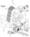
Figure 5 shows a larger-scale detail ofFigure 4 ; -
Figures 6-13 show eight views in perspective of part of theFigure 4 packing unit at successive blank-folding stages. -
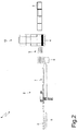
Number 1 inFigures 1 and2 indicates as a whole a packing (i.e. boxing) machine for packingloose packages 2 in acardboard box 3 formed by folding and gluing a blank 4. -
Packing machine 1 comprises an input conveyor 5 (shown schematically inFigure 2 ) which is fed by an upstream packing machine (not shown) with a succession of spaced packages 2 (i.e. equally spaced a given distance apart), and feeds the succession of spacedpackages 2 forward continuously (i.e. at constant speed). Downstream frominput conveyor 5, aninitial grouping unit 6 forms a number oflines 7 of successive adjacentindividual packages 2. Downstream frominitial grouping unit 6, a final grouping unit 8 (shown schematically inFigure 2 ) superimposes a number oflines 7 of packages to formgroups 9 ofpackages 2. And downstream fromfinal grouping unit 8, a packing unit 10 (shown schematically inFigure 1 ) packs eachgroup 9 ofpackages 2 inside arespective cardboard box 3. - As shown in
Figure 3 , each blank 4 comprises: apanel 11 forming a lateral wall ofcardboard box 3; apanel 12 forming a bottom wall ofcardboard box 3; apanel 13 forming a further lateral wall ofcardboard box 3; and apanel 14 forming a top wall ofcardboard box 3.Panel 14 has afastening tab 15 which is glued to the inside ofpanel 11 to form blank 4 into a firm tubular shape. And each of panels 11-14 comprises twowings 16 located at opposite ends of panel 11-14 to form respective parts of the end walls ofcardboard box 3. - As shown in
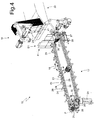
Figure 4 ,packing unit 10 comprises apacking conveyor 17 with a number ofpockets 18, which are fed cyclically and intermittently (i.e. in cyclically alternating stop-go steps) along a straight horizontal packing path P. As shown inFigure 1 , packing path P commences at a feed station S1 where a blank 4 is fed and folded into 'U' inside acorresponding pocket 18 onpacking conveyor 17. Downstream from feed station S1, packing path P extends through a further feed station S2 where agroup 9 ofpackages 2 is inserted longitudinally into blank 4 insidepocket 18 onpacking conveyor 17. Downstream from feed station S2, packing path P extends through a packing station S3 where blank 4 is folded aboutgroup 9 ofpackages 2 to formcardboard box 3. And, finally, packing path P terminates at an output station S4 wherecardboard box 3 is expelled longitudinally frompocket 18 on packingconveyor 17 and fed to an output ofpacking machine 1. - As shown in
Figure 4 ,packing unit 10 comprises afeed device 19 located at feed station S1 to insertblanks 4 successively insidecorresponding pockets 18 onpacking conveyor 17.Feed device 19 comprises astore 20 containing a stack ofblanks 4; and twosuction pickup heads store 20 and insert blank 4 inside acorresponding pocket 18 onpacking conveyor 17. -
Packing conveyor 17 comprises at least afirst conveyor belt 23; and at least asecond conveyor belt 24 separate from, parallel to, and alongsidefirst conveyor belt 23. First andsecond conveyor belts pocket 18. - More specifically, as shown in
Figure 4 ,packing conveyor 17 comprises twoconveyor belts 23 extending along packing path P; and twoconveyor belts 24 also extending along packing path P. The twoconveyor belts 23 and twoconveyor belts 24 are positioned side by side and parallel, and alternate with one another. In other words, oneconveyor belt 24 is located between twoconveyor belts 23 and vice versa (i.e. oneconveyor belt 23 is located between two conveyor belts 24).Conveyor belts pocket 18, i.e. eachconveyor belt pocket 18.Conveyor belts 23 support a number ofvertical retaining members 25, each of which projects perpendicularly (i.e. projects upwards) from thecorresponding conveyor belt 23, and defines a front wall of arespective pocket 18 in the direction of packing P. Andconveyor belts 24 support a number ofvertical retaining members 26, each of which projects perpendicularly (i.e. projects upwards) from thecorresponding conveyor belt 24, and defines a rear wall of arespective pocket 18 in the direction of packing P. - The distance between retaining
member 25 and retainingmember 26 in the direction of packing path P defines the length L ofpocket 18, as shown by way of example inFigures 4 and6 . - Said length L is therefore adjustable according to the format of blank 4. And, by adjusting the length of
pocket 18 on the conveyor,blanks 4 of different formats (i.e. different sizes) can be retained inside the same pocket without changing any component parts onpacking unit 10. -
Pockets 18 on packingconveyor 17 are arranged successively and spaced apart (i.e. a given distance is left between eachpocket 18 and the two adjacent pockets 18) by a spacing distance S defined by the distance between retainingmember 26 of onepocket 18 and retainingmember 25 of theupstream pocket 18 in the direction of packing path P (as shown inFigures 4 and6 ).Pockets 18 are bounded at the front by two corresponding retainingmembers 25 onconveyor belts 23, and at the rear by two corresponding retainingmembers 26 onconveyor belts 24. In other words, for eachpocket 18 on packingconveyor 17, the front wall ofpocket 18 is always defined by two retainingmembers 25 on the two side by side, spaced conveyor belts 23 (aconveyor belt 24 is interposed between the two conveyor belts 23), and the rear wall ofpocket 18 is always defined by two retainingmembers 26 on the two side by side, spaced conveyor belts 24 (aconveyor belt 23 is interposed between the two conveyor belts 24). It is important to note that each retainingmember 25 only defines the front wall of acorresponding pocket 18 onpacking conveyor 17, and each retainingmember 26 only defines the rear wall of acorresponding pocket 18 onpacking conveyor 17. - Spacing distance S therefore allows the two
suction pickup heads - To adjust length L, packing
conveyor 17 produces a relative movement betweenconveyor belt 23 andconveyor belt 24, to move retainingmembers pocket 18 towards or away from each other according to the format (size) of blank 4. - Each
conveyor belt 23 is looped about twoend pulleys end pulley 27 is mounted idly (i.e. rotates freely about a central axis of rotation); while eachend pulley 28 is powered, i.e. is connected mechanically to a commonelectric motor 29 which rotates both poweredend pulleys 28 synchronously. Likewise, eachconveyor belt 24 is looped about twoend pulleys end pulley 30 is mounted idly (i.e. rotates freely about a central axis of rotation); while eachend pulley 31 is powered, i.e. is connected mechanically to a commonelectric motor 32 which rotates both poweredend pulleys 31 synchronously, and is separate from and independent ofelectric motor 29. - In actual use,
end pulleys conveyor belts 23 can be operated out of phase with respect toend pulleys conveyor belts 24 to adjust the length ofpockets 18 according to the format (i.e. size) of blank 4, by producing a relative movement betweenbelt 23 andbelt 24, as described previously. In other words, the timing ofend pulleys conveyor belts 23 andend pulleys conveyor belts 24 can be adjusted to produce a relative movement between the twoconveyor belts 23 and the twoconveyor belts 24, and so move retainingmembers pocket 18 towards or away from each other to adjust the length ofpockets 18 according to the format (i.e. size) of blank 4. In actual fact, only the timing of poweredend pulleys 28 and 31 (whose angular position is controlled actively byelectric motors 29 and 32) is actively adjusted, and the timing ofidle end pulleys end pulleys end pulleys packing machine 1 is off and empty, i.e. during a format changeover to adaptpacking machine 1 to cardboard boxes 3 (and therefore blanks 4) of a different format (i.e. size). More specifically, when working with wider ornarrower panels 12 ofblanks 4, the length of eachpocket 18 is adjusted to always equal the width ofpanels 12 of blanks 4 (obviously, allowing for the necessary tolerances). - In the
Figure 4 embodiment, powered end pulleys 28 and 31 are driven by two separate independentelectric motors electric motors electric motor 32, which drives both powered end pulleys 28 and 31; so powered end pulleys 28 and 31 can be operated mechanically out of phase with respect to the drive shaft ofelectric motor 32 to adjust the length ofpockets 18 according to the format of blank 4. In other words, the timing between powered end pulleys 28, 31 and the drive shaft ofelectric motor 32 can be adjusted manually when packingmachine 1 is off. -
Feed device 19 comprises asuction pickup head 21 which engagespanel 11 of blank 4 insidestore 20; and asuction pickup head 22 which engagespanel 13 of blank 4 instore 20.Feed device 19 also comprises actuatingdevices store 20, to a release position at packingconveyor 17, to insert blank 4 intopocket 18 on packingconveyor 17, and to release blank 4, folded into a 'U', insidepocket 18. - Actuating
devices store 20 according to the format (i.e. size) of blank 4. So, in addition toflexible pockets 18, pickup heads 21, 22 are also designed for maximum flexibility, to work with blanks of different sizes. - As the pickup heads move from the withdrawal to the release position, actuating
devices pickup head 21 andpickup head 22 to fold blank 4 into a 'U' before it is inserted intopocket 18 on packingconveyor 17. More specifically, as the pickup heads move from the withdrawal position to the release position, operation ofactuating devices - This also allows for flexibility in folding the blank into a 'U', by allowing the same blank or different blanks to be folded into a 'U' at different portions.
- As shown in
Figure 5 ,feed device 19 comprises actuatingdevice 33 which movespickup head 21 with two degrees of rotational freedom to perform the movement described below; andactuating device 34 which movespickup head 22 also with two degrees of rotational freedom to perform the movement described below. -
Actuating device 33 comprises a supportingplate 35 hinged (i.e. fitted in rotary manner) to a fixed frame (not shown) of packingmachine 1, and which is rotated with respect to the fixed frame about a horizontal axis ofrotation 36 by anelectric motor 37 offset with respect to axis ofrotation 36. More specifically, the shaft ofelectric motor 37 is connected mechanically to supportingplate 35 by a mechanism comprising two mutually hinged arms. Supportingplate 35 is fitted with anarm 38 hinged (i.e. fitted in rotary manner) to supportingplate 35, and which is rotated with respect to supportingplate 35 about a horizontal axis of rotation 39 (parallel to axis of rotation 36) by an electric motor 40 (also fitted to supportingplate 35 and offset with respect to axis of rotation 39).Arm 38 is hinged at one end to supportingplate 35, and at the opposite end is connected rigidly topickup head 21. In other words,pickup head 21 is connected rigidly to one end ofarm 38. So actuatingdevice 33 can rotatepickup head 21 about both axes ofrotation -
Actuating device 34 comprises anarm 41 hinged (i.e. fitted in rotary manner) to the fixed frame (not shown) of packingmachine 1, and which is rotated with respect to the fixed frame about a horizontal axis ofrotation 42 by anelectric motor 43 coaxial with axis ofrotation 42.Arm 41 is fitted with anarm 44 hinged (i.e. fitted in rotary manner) toarm 41, and which is rotated with respect toarm 41 about a horizontal axis of rotation 45 (parallel to axis of rotation 42) by an electric motor 46 (also fitted toarm 41 and offset with respect to axis of rotation 45). More specifically, the shaft ofelectric motor 46 is connected mechanically toarm 44 by a mechanism comprising two mutually hinged arms.Arm 44 is hinged at one end toarm 41, and at the opposite end is connected rigidly topickup head 22. In other words,pickup head 22 is connected rigidly to one end ofarm 44. So actuatingdevice 34 can rotatepickup head 22 about both axes ofrotation - Normally, when making a format change, i.e. changing over to
blanks 4 of different sizes, the movements of the two pickup heads 21 and 22 (i.e. the laws of motion ofelectric motors machine 1 is off and empty, i.e. during a format changeover to adapt packingmachine 1 to cardboard boxes 3 (and therefore blanks 4) of a different format (i.e. size). In one possible embodiment, actuatingdevice 33 and/oractuating device 34 may be fitted to the frame of packingmachine 1 to move vertically to adjust the vertical position ofpickup head 21 and/orpickup head 22 according to the format (i.e. size) of blank 4. In one possible embodiment,actuating devices devices actuating devices - As shown in
Figure 5 , at feed station S1, two movable folding devices 47 (only one shown inFigure 5 ) are located on opposite sides of packingconveyor 17, and each mounted to rotate about a horizontal axis ofrotation 48, parallel to packing path P, under the control of anelectric motor 49. Eachmovable folding device 47 is moved cyclically byelectric motor 49 between an engaged or lowered position (shown, for example, inFigure 5 ), in whichmovable folding device 47 folds down acorresponding wing 16 ofpanel 12 of blank 4, and a release or raised position (shown, for example, inFigure 10 ), in whichmovable folding device 47 is relatively distant frompocket 18 at feed station S1, so as not to obstruct insertion of blank 4 intopocket 18. Downstream from eachmovable folding device 47 and along packing path P (i.e. along the path of packing conveyor 17), a fixed folding device 50 (shown schematically inFigure 13 ) continues the work ofmovable folding device 47 to keepwing 16 ofpanel 12 of each blank 4 folded down. - Operation of packing
unit 10 to feed a blank 4 into apocket 18 on packingconveyor 17 will now be described with reference toFigures 6-13 . - To begin with, as shown in
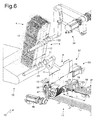
Figure 6 ,actuating device 33moves pickup head 21 to engage (i.e. grip and retain by suction)panel 11 of blank 4 at the outlet of store 20 (i.e. the first blank 4 in the stack in store 20); and, at the same time,actuating device 34moves pickup head 22 to engage (i.e. grip and retain by suction)panel 13 of blank 4 at the outlet of store 20 (i.e. the first blank 4 in the stack in store 20). - Next, as shown in
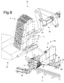
Figures 7-11 ,actuating devices store 20 to a release position at packingconveyor 17, to insert blank 4 insiderespective pocket 18 on packingconveyor 17. - Finally, as shown in
Figures 12 and13 , pickup heads 21, 22 (by cutting off suction) release blank 4, folded into a 'U', insiderespective pocket 18 on packingconveyor 17, and move back to the withdrawal position at the outlet ofstore 20 to repeat the feed cycle on the next blank 4. - As shown in
Figures 7-10 , as the pickup heads move from the withdrawal to the release position, actuatingdevices pickup head 21 andpickup head 22 to fold blank 4 into a 'U' before it is inserted intorespective pocket 18 on packingconveyor 17. In other words, pickup heads 21, 22 are initially oriented the same way at different heights (as shown inFigure 6 ), and are moved with respect to each other so that they are eventually oppositely oriented and at the same height (as shown inFigure 11 ). As a result, the initially flat blank 4 (Figure 6 ) is folded into a 'U' (Figure 11 ) by rotatingpanels panel 12. It is important to note that the relative movement between pickup heads 21 and 22 comprisesrotating pickup head 21 180° with respect topickup head 22. The effect of this relative movement between pickup heads 21 and 22 is that the initially equally-oriented pickup heads 21, 22 (Figure 6 ) are eventually oppositely-oriented (Figure 11 ). - In a preferred embodiment, pickup heads 21 and 22 rotate
panels panel 12 before inserting the U-folded blank 4 insidepocket 18 on packingconveyor 17; next, pickup heads 21 and 22 rotatepanels panel 12, so thatpanels panel 12 when the U-folded blank 4 is insidepocket 18 on packingconveyor 17. In other words, before inserting the U-folded blank 4 intopocket 18 on packingconveyor 17, pickup heads 21 and 22 "close' the 'U' formed bypanels pocket 18; and, once the U-folded blank 4 is inserted insidepocket 18, pickup heads 21 and 22 'open' the 'U' formed bypanels panels panel 12. - In a preferred embodiment, as the U-folded blank 4 is inserted inside
pocket 18 on packingconveyor 17, the twomovable folding devices 47 are set to the release position (shown, for example, inFigures 10 and11 ), in which eachmovable folding device 47 is relatively distant frompocket 18 at feed station S1, so as not to obstruct insertion of blank 4 intopocket 18. Once the U-folded blank 4 is inserted insidepocket 18 on packingconveyor 17, the twomovable folding devices 47 are moved into the engaged position (shown, for example, inFigure 12 ), in which eachmovable folding device 47 folds down acorresponding wing 16 ofpanel 12 of blank 4.Movable folding devices 47 remain in the engagedposition engaging wings 16 ofpanel 12 until the movement of packingconveyor 17 withdrawswings 16 frommovable folding devices 47; and, directly downstream frommovable folding devices 47, fixedfolding devices 50 keepwings 16 ofpanel 12 in the down-folded position as packingconveyor 17 feeds blank 4 along packing path P (more specifically, through feed station S2). -
Movable folding devices 47 and fixedfolding devices 50 serve to fold down, and keep folded down,wings 16 ofpanel 12 of blank 4, so that, at feed station S2,wings 16 ofpanel 12 in no way impede insertion ofgroup 9 ofpackages 2 into blank 4 insidepocket 18 on packingconveyor 17. -
Packing unit 10 described has numerous advantages. - Firstly, packing
unit 10 described is highly flexible, i.e. provides for rapidly changing the format (i.e. size) ofblanks 4. - The format (i.e. size) of
blanks 4 can be changed by simply appropriately altering the movements of pickup heads 21 and 22, which can be done by software adjusting (i.e. with no physical work involved) the laws of motion ofelectric motors unit 10. Moreover, the format (i.e. size) ofblanks 4 can be changed by simply adjusting the length ofpockets 18 on packingconveyor 17, by software adjusting (i.e. with no physical work involved) the law of motion of at least one ofelectric motors unit 10. In other words, all the operations involved in changing the format (i.e. size) ofblanks 4 are performed without changing any actual component parts of packingunit 10, and with no manual labour on the part of the operator. - Secondly, packing
unit 10 described is also cheap and easy to produce. - Finally, packing
unit 10 described enables extremely high output rates to be achieved, by treating blanks 4 'gently', i.e. not subjecting them to severe mechanical stress (i.e. sharp acceleration/deceleration).
Claims (11)
- A packing unit (10) for folding a blank (4) on a packing machine (1); the packing unit (10) comprising:a packing conveyor (17) having at least one pocket (18) for receiving the blank (4); anda feed device (19) for inserting the blank (4) into the pocket (18) on the packing conveyor (17);wherein the packing conveyor (17) comprises: at least a first conveyor belt (23), and at least a second conveyor belt (24) separate from, parallel to, and alongside the first conveyor belt (23), said first (23) and second (24) conveyor belts defining a bottom wall of the pocket (18); a first retaining member (25), which projects perpendicularly from the first conveyor belt (23) and defines a front wall of the pocket (18) in the direction of the packing path (P); and a second retaining member (26), which projects perpendicularly from the second conveyor belt and defines a rear wall of the pocket (18) in the direction of the packing path (P); andwherein the distance between said first retaining member (25) and said second retaining member (26) in the direction of the packing path (P) defines the length (L) of said pocket (18);wherein said length (L) is variable according to the format of said blank (4);the packing unit (10) being characterized in that the feed device (19) comprises:a first suction pickup head (21), which engages a first panel (11) of the blank (4) inside a store (20);a second suction pickup head (22), which engages a second panel (13) of the blank (4) inside the store (20); andactuating devices (33, 34) for moving the pickup heads (21, 22) from a withdrawal position at the store (20) to a release position at the packing conveyor (17), to insert the blank (4) inside the pocket (18) on the packing conveyor (17), and then release the blank (4), folded into a 'U', inside the pocket (18) on the packing conveyor (17);
andxwherein said actuating devices (33, 34) alters the distance between said pickup heads (21, 22) and said packing unit at said store (20) according to the format of said blank (4). - A packing unit (10) as claimed in Claim 1, wherein said packing conveyor (17) produces a relative movement between said first (23) and second (24) conveyor belts, to move said retaining members (25, 26) of said pocket (18) towards or away from each other according to the format of said blank (4).
- A packing unit (10) as claimed in Claim 1 or 2, wherein the packing conveyor (17) comprises a number of successive pockets (18), each bounded at the front by a corresponding first retaining member (25), and at the rear by a corresponding second retaining member (26); each first retaining member (25) only defines the front wall of a corresponding pocket (18); and each second retaining member (26) only defines the rear wall of a corresponding pocket (18); and
said pockets (18) being spaced apart by a spacing distance (S) defined by the distance between said second retaining member (26) of a pocket (18) and said first retaining member (25) of the upstream pocket (18) in the direction of the packing path (P). - A packing unit (10) as claimed in Claim 1, 2 or 3, wherein the packing conveyor (17) comprises:two first conveyor belts (23) having respective first retaining members (25); andtwo second conveyor belts (24) having respective second retaining members (26) and alternating with the first conveyor belts (23).
- A packing unit (10) as claimed in Claim 4, wherein said two first conveyor belts (23) and said two second conveyor belts (24) are positioned side by side and parallel, and alternate with one another.
- A packing unit (10) as claimed in one of Claims 1 to 5, wherein:the first conveyor belt (23) is looped about respective first end pulleys (27, 28);the second conveyor belt is looped about respective second end pulleys (30, 31) parallel to and alongside the first end pulleys (27, 28); andthe first end pulleys (27, 28) can be operated out of phase with respect to the second end pulleys (30, 31) to adjust said length (L) of said pocket (18) according to the format of the blank (4).
- A packing unit (10) as claimed in Claim 6, wherein the packing conveyor (17) comprises:a first motor (29), which rotates a powered first end pulley (28); anda second motor (32), which is separate from and independent of the first motor (29), and rotates a powered second end pulley (31).
- A packing unit (10) as claimed in Claim 6, wherein the packing conveyor (17) comprises one motor (32), which rotates both a powered first end pulley (28) and a powered second end pulley (31).
- A packing unit (10) as claimed in Claim 8, wherein at least one powered end pulley (28; 31) can be operated mechanically out of phase with respect to the drive shaft of the motor (32) to adjust said length (L) of the pocket (18) according to the format of the blank (4).
- A packing unit (10) as claimed in one of Claims 1 to 9, wherein, as the pickup heads are moved from the withdrawal position to the release position, the actuating devices (33, 34) produce a relative movement between the first pickup head (21) and the second pickup head (22) to fold the blank (4) into a 'U' before the blank (4) is inserted into the pocket (18) on the packing conveyor (17); and
as said pickup heads move from the withdrawal position to the release position, operation of said actuating devices (33, 34) is adjustable to adjust the movements of said pickup heads (21, 22) according to the format of said blank (4). - A packing method for folding a blank (4) on a packing machine (1); the packing method comprising the steps of:feeding a packing conveyor (17), having at least one pocket (18) for receiving the blank (4), along a packing path (P); andinserting the blank (4) into the pocket (18) on the packing conveyor (17) by means of a feed device (19);the packing conveyor (17) comprising: at least a first conveyor belt (23), and at least a second conveyor belt (24) separate from, parallel to, and alongside the first conveyor belt (23), said first (23) and second (24) conveyor belts defining a bottom wall of the pocket (18); a first retaining member (25), which projects perpendicularly from the first conveyor belt (23) and defines a front wall of the pocket (18) in the direction of the packing path (P); and a second retaining member (26), which projects perpendicularly from the second conveyor belt and defines a rear wall of the pocket (18) in the direction of the packing path (P);the distance between said first retaining member (25) and said second retaining member (26) defining the length (L) of said pocket (18) in the direction of the packing path (P); and adjusting said length (L) according to the format of said blank (4).the packing method being characterized in that the feed device (19) comprises: a first suction pickup head (21), which engages a first panel (11) of the blank (4) inside a store (20); and a second suction pickup head (22), which engages a second panel (13) of the blank (4) inside the store (20);and the method comprises the further step of moving the pickup heads (21, 22), by means of appropriate actuating devices (33, 34), from a withdrawal position at the store (20) to a release position at the packing conveyor (17), to insert the blank (4) inside the pocket (18) on the packing conveyor (17), and then release the blank (4), folded into a 'U', inside the pocket (18) on the packing conveyor (17);and said actuating devices (33, 34) altering the distance between said pickup heads (21, 22) and said packing unit at said store (20) according to the format of said blank (4).
Applications Claiming Priority (1)
| Application Number | Priority Date | Filing Date | Title |
|---|---|---|---|
| IT000387A ITBO20130387A1 (en) | 2013-07-23 | 2013-07-23 | UNIT AND METHOD OF WRAPPING FOR THE BENDING OF A BLOCKED IN A PACKING MACHINE. |
Publications (2)
| Publication Number | Publication Date |
|---|---|
| EP2829483A1 EP2829483A1 (en) | 2015-01-28 |
| EP2829483B1 true EP2829483B1 (en) | 2016-05-25 |
Family
ID=49261597
Family Applications (1)
| Application Number | Title | Priority Date | Filing Date |
|---|---|---|---|
| EP14178239.1A Active EP2829483B1 (en) | 2013-07-23 | 2014-07-23 | Packing unit and method for folding a blank on a packing machine |
Country Status (4)
| Country | Link |
|---|---|
| US (1) | US9713911B2 (en) |
| EP (1) | EP2829483B1 (en) |
| CN (1) | CN104340414B (en) |
| IT (1) | ITBO20130387A1 (en) |
Families Citing this family (18)
| Publication number | Priority date | Publication date | Assignee | Title |
|---|---|---|---|---|
| ITBO20130388A1 (en) * | 2013-07-23 | 2015-01-24 | Gd Spa | UNIT AND METHOD OF WRAPPING FOR THE BENDING OF A BLOCKED IN A PACKING MACHINE. |
| WO2015187004A1 (en) * | 2014-06-05 | 2015-12-10 | N.V. Nutricia | Method of manufacturing and filling a package and corresponding package |
| EP3064343B1 (en) * | 2015-03-02 | 2019-01-30 | Tetra Laval Holdings & Finance S.A. | A folding apparatus for folding sheet packaging elements |
| CH711266A2 (en) * | 2015-06-24 | 2016-12-30 | Ferag Ag | A method for producing collections of pre-products by transferring a second pre-product around a first pre-product as well as a device for carrying out this method. |
| ITUB20154231A1 (en) * | 2015-10-08 | 2017-04-08 | Gima Spa | INSERTION STATION OF PRODUCTS WITH DIFFERENT TYPOLOGICAL BODIES |
| ITUB20154217A1 (en) * | 2015-10-08 | 2017-04-08 | Gima Spa | TRANSPORT AND FORMING LINE FOR DIFFERENT TYPOLOGICAL CASES |
| ITUB20154224A1 (en) * | 2015-10-08 | 2017-04-08 | Gima Spa | FORMING AND FILLING MACHINE FOR DIFFERENT TYPOLOGICAL CASES |
| ITUB20160604A1 (en) * | 2016-02-09 | 2017-08-09 | Ima Spa | UNITS AND METHOD FOR PLACING OBJECTS WITHIN BOXES. |
| CN105599948B (en) * | 2016-03-04 | 2017-12-01 | 巢湖学院 | A kind of semi-automatic carton forming and packaging system |
| RU2019127347A (en) * | 2017-02-01 | 2021-03-02 | Хикоф Аг | METHOD AND LINE FOR CODE FOR ASSIGNING SERIAL NUMBERS TO A LOT OF PRODUCTS |
| DE102017114814A1 (en) * | 2017-07-03 | 2019-01-03 | Sig Technology Ag | Method and apparatus for forming unilaterally open packing bodies with an oscillating gripper |
| US11305903B2 (en) * | 2018-04-05 | 2022-04-19 | Avercon BVBA | Box template folding process and mechanisms |
| FR3100800B1 (en) * | 2019-09-16 | 2021-10-29 | Sidel Packing Solutions | Folding container forming device and method |
| CN110705083B (en) * | 2019-09-25 | 2023-03-31 | 上海烟草集团有限责任公司 | Method, device, equipment and medium for automatically designing parameters of transparent paper packaging machine |
| US20230030864A1 (en) * | 2019-11-07 | 2023-02-02 | Tetra Laval Holdings & Finance S.A. | Carboard packer, and a blank picker for a cardboard packer |
| IT202000005005A1 (en) * | 2020-03-09 | 2021-09-09 | Cmc Spa | PACKAGING MACHINERY WITH FOLDING AND CLOSING STATION OF A PREFORMING CARTON AND RELATIVE METHOD |
| IT202000011656A1 (en) * | 2020-05-20 | 2021-11-20 | Tiber Pack S P A | PICKING SYSTEM FOR PICKING CARDBOARD BLANKS FROM A WAREHOUSE |
| CN114735313B (en) * | 2021-11-29 | 2023-12-15 | 郑州旺丰元纸制品有限公司 | Automatic production line for processing cartons by using paperboards |
Family Cites Families (12)
| Publication number | Priority date | Publication date | Assignee | Title |
|---|---|---|---|---|
| US4429864A (en) * | 1981-06-22 | 1984-02-07 | R. A. Jones & Co. Inc. | High speed carton feeder |
| DE3307855A1 (en) * | 1983-03-05 | 1984-09-06 | Leifeld und Lemke Maschinenfabrik GmbH & Co KG, 4993 Rahden | METHOD AND DEVICE FOR PRODUCING COLLECTOR PACKS |
| US4571236A (en) * | 1983-12-05 | 1986-02-18 | R. A. Jones & Co. Inc. | Carton squaring mechanism |
| US5546734A (en) * | 1993-09-02 | 1996-08-20 | Riverhood International Corporation | Packaging machine and method of packaging articles |
| IT1273267B (en) * | 1994-03-23 | 1997-07-07 | Oam Spa | DEVICE FOR THE OPENING OF TUBULAR DIE CUTS AND FOR THE TRANSFER OF THE OPEN DIE CUTS TO A PACKAGING LINE |
| NZ297315A (en) * | 1994-10-03 | 1997-09-22 | Riverwood Int Corp | Device for erecting carton from a collapsed carrier sleeve: upper flaps of carton ride over a cam surface whilst the lower flaps ride under the cam surface |
| US5937620A (en) * | 1995-03-03 | 1999-08-17 | The Mead Corporation | Packaging machine for multi-packs |
| US5928123A (en) * | 1996-07-17 | 1999-07-27 | Davis Engineering Llc | Vacuum holder for automated carton erecting machine |
| ITBO20030077A1 (en) * | 2003-02-20 | 2004-08-21 | Gd Spa | METHOD AND UNIT FOR HANDLING AND TREATMENT |
| JP4054274B2 (en) * | 2003-03-31 | 2008-02-27 | ニグレリ システムズ インコーポレイテッド | Loading device for packaged products |
| IT1401845B1 (en) * | 2010-10-14 | 2013-08-28 | Marchesini Group Spa | SYSTEM FOR THE TRANSFER OF TUBULAR PUNCHERS IN CONFIGURATION OPEN TO THE POWER SUPPLY LINE OF A PACKAGING MACHINE |
| CN102849234B (en) * | 2012-09-21 | 2014-11-05 | 瑞安市华科包装机械有限公司 | High-speed automatic medicine packing machine |
-
2013
- 2013-07-23 IT IT000387A patent/ITBO20130387A1/en unknown
-
2014
- 2014-07-22 CN CN201410351856.3A patent/CN104340414B/en active Active
- 2014-07-22 US US14/337,463 patent/US9713911B2/en active Active
- 2014-07-23 EP EP14178239.1A patent/EP2829483B1/en active Active
Also Published As
| Publication number | Publication date |
|---|---|
| US20150031519A1 (en) | 2015-01-29 |
| CN104340414A (en) | 2015-02-11 |
| US9713911B2 (en) | 2017-07-25 |
| CN104340414B (en) | 2018-05-11 |
| ITBO20130387A1 (en) | 2015-01-24 |
| EP2829483A1 (en) | 2015-01-28 |
Similar Documents
| Publication | Publication Date | Title |
|---|---|---|
| EP2829483B1 (en) | Packing unit and method for folding a blank on a packing machine | |
| EP2829481B1 (en) | Packing method and unit for feeding a blank on a packing machine | |
| RU2334668C2 (en) | Method and device for producing vessels packages | |
| US6764436B1 (en) | Method and apparatus for squaring cases | |
| US10647457B2 (en) | Folding device, packaging facility for articles, and method for folding side flaps of external cardboard packagings | |
| US10183813B2 (en) | Carton feeder device and method for feeding a carton to a conveyor track | |
| EP2287076B1 (en) | Machine for cartoning products | |
| CA2798513C (en) | Method and folding device for handling l-boards | |
| US9745146B2 (en) | Conveying device | |
| EP3083417B1 (en) | Apparatus for feeding carton blanks from a magazine to carriers | |
| CN210338481U (en) | Automatic box filling machine | |
| EP3013717B1 (en) | Group-forming method and unit for forming a group of products on a packing machine | |
| JP3176088U (en) | Box making equipment | |
| EP4051595A1 (en) | Grouping unit and method to form a group consisting of two wraps, each containing a group of smoking articles | |
| CN206494184U (en) | A kind of multifunctional high speed packing machine falling type cardboard storehouse | |
| CN206494174U (en) | A kind of multifunctional high speed packing machine differential feed arrangement | |
| EP3816056A1 (en) | Hopper for a packer machine to pack smoking articles | |
| JP6045883B2 (en) | Rear side flap bending device | |
| EP1757521B1 (en) | A machine for packing products in cases | |
| CN206494188U (en) | A kind of multifunctional high speed packing machine Cheng Ye mechanisms | |
| JP3945258B2 (en) | Caser | |
| CN206494172U (en) | A kind of multifunctional high speed packing machine material-pulling device | |
| EP1584456A1 (en) | Method and device for conveying and erecting boxes | |
| JP2004224010A (en) | Manufacturing method and manufacturing device for shock absorber for packaging |
Legal Events
| Date | Code | Title | Description |
|---|---|---|---|
| 17P | Request for examination filed |
Effective date: 20140723 |
|
| AK | Designated contracting states |
Kind code of ref document: A1 Designated state(s): AL AT BE BG CH CY CZ DE DK EE ES FI FR GB GR HR HU IE IS IT LI LT LU LV MC MK MT NL NO PL PT RO RS SE SI SK SM TR |
|
| AX | Request for extension of the european patent |
Extension state: BA ME |
|
| PUAI | Public reference made under article 153(3) epc to a published international application that has entered the european phase |
Free format text: ORIGINAL CODE: 0009012 |
|
| R17P | Request for examination filed (corrected) |
Effective date: 20150728 |
|
| RBV | Designated contracting states (corrected) |
Designated state(s): AL AT BE BG CH CY CZ DE DK EE ES FI FR GB GR HR HU IE IS IT LI LT LU LV MC MK MT NL NO PL PT RO RS SE SI SK SM TR |
|
| GRAP | Despatch of communication of intention to grant a patent |
Free format text: ORIGINAL CODE: EPIDOSNIGR1 |
|
| RIC1 | Information provided on ipc code assigned before grant |
Ipc: B65B 43/26 20060101ALN20151113BHEP Ipc: B65B 59/00 20060101AFI20151113BHEP Ipc: B31B 1/58 20060101ALI20151113BHEP Ipc: B31B 1/12 20060101ALI20151113BHEP Ipc: B65G 47/84 20060101ALN20151113BHEP |
|
| INTG | Intention to grant announced |
Effective date: 20151204 |
|
| GRAS | Grant fee paid |
Free format text: ORIGINAL CODE: EPIDOSNIGR3 |
|
| GRAA | (expected) grant |
Free format text: ORIGINAL CODE: 0009210 |
|
| AK | Designated contracting states |
Kind code of ref document: B1 Designated state(s): AL AT BE BG CH CY CZ DE DK EE ES FI FR GB GR HR HU IE IS IT LI LT LU LV MC MK MT NL NO PL PT RO RS SE SI SK SM TR |
|
| REG | Reference to a national code |
Ref country code: GB Ref legal event code: FG4D |
|
| REG | Reference to a national code |
Ref country code: CH Ref legal event code: EP |
|
| REG | Reference to a national code |
Ref country code: IE Ref legal event code: FG4D Ref country code: AT Ref legal event code: REF Ref document number: 802081 Country of ref document: AT Kind code of ref document: T Effective date: 20160615 |
|
| REG | Reference to a national code |
Ref country code: DE Ref legal event code: R096 Ref document number: 602014002076 Country of ref document: DE |
|
| REG | Reference to a national code |
Ref country code: FR Ref legal event code: PLFP Year of fee payment: 3 |
|
| REG | Reference to a national code |
Ref country code: LT Ref legal event code: MG4D |
|
| REG | Reference to a national code |
Ref country code: NL Ref legal event code: MP Effective date: 20160525 |
|
| PG25 | Lapsed in a contracting state [announced via postgrant information from national office to epo] |
Ref country code: FI Free format text: LAPSE BECAUSE OF FAILURE TO SUBMIT A TRANSLATION OF THE DESCRIPTION OR TO PAY THE FEE WITHIN THE PRESCRIBED TIME-LIMIT Effective date: 20160525 Ref country code: NL Free format text: LAPSE BECAUSE OF FAILURE TO SUBMIT A TRANSLATION OF THE DESCRIPTION OR TO PAY THE FEE WITHIN THE PRESCRIBED TIME-LIMIT Effective date: 20160525 Ref country code: LT Free format text: LAPSE BECAUSE OF FAILURE TO SUBMIT A TRANSLATION OF THE DESCRIPTION OR TO PAY THE FEE WITHIN THE PRESCRIBED TIME-LIMIT Effective date: 20160525 Ref country code: NO Free format text: LAPSE BECAUSE OF FAILURE TO SUBMIT A TRANSLATION OF THE DESCRIPTION OR TO PAY THE FEE WITHIN THE PRESCRIBED TIME-LIMIT Effective date: 20160825 |
|
| REG | Reference to a national code |
Ref country code: AT Ref legal event code: MK05 Ref document number: 802081 Country of ref document: AT Kind code of ref document: T Effective date: 20160525 |
|
| PG25 | Lapsed in a contracting state [announced via postgrant information from national office to epo] |
Ref country code: RS Free format text: LAPSE BECAUSE OF FAILURE TO SUBMIT A TRANSLATION OF THE DESCRIPTION OR TO PAY THE FEE WITHIN THE PRESCRIBED TIME-LIMIT Effective date: 20160525 Ref country code: SE Free format text: LAPSE BECAUSE OF FAILURE TO SUBMIT A TRANSLATION OF THE DESCRIPTION OR TO PAY THE FEE WITHIN THE PRESCRIBED TIME-LIMIT Effective date: 20160525 Ref country code: GR Free format text: LAPSE BECAUSE OF FAILURE TO SUBMIT A TRANSLATION OF THE DESCRIPTION OR TO PAY THE FEE WITHIN THE PRESCRIBED TIME-LIMIT Effective date: 20160826 Ref country code: PT Free format text: LAPSE BECAUSE OF FAILURE TO SUBMIT A TRANSLATION OF THE DESCRIPTION OR TO PAY THE FEE WITHIN THE PRESCRIBED TIME-LIMIT Effective date: 20160926 Ref country code: LV Free format text: LAPSE BECAUSE OF FAILURE TO SUBMIT A TRANSLATION OF THE DESCRIPTION OR TO PAY THE FEE WITHIN THE PRESCRIBED TIME-LIMIT Effective date: 20160525 Ref country code: ES Free format text: LAPSE BECAUSE OF FAILURE TO SUBMIT A TRANSLATION OF THE DESCRIPTION OR TO PAY THE FEE WITHIN THE PRESCRIBED TIME-LIMIT Effective date: 20160525 |
|
| PG25 | Lapsed in a contracting state [announced via postgrant information from national office to epo] |
Ref country code: BE Free format text: LAPSE BECAUSE OF NON-PAYMENT OF DUE FEES Effective date: 20160731 Ref country code: IT Free format text: LAPSE BECAUSE OF FAILURE TO SUBMIT A TRANSLATION OF THE DESCRIPTION OR TO PAY THE FEE WITHIN THE PRESCRIBED TIME-LIMIT Effective date: 20160525 |
|
| PG25 | Lapsed in a contracting state [announced via postgrant information from national office to epo] |
Ref country code: RO Free format text: LAPSE BECAUSE OF FAILURE TO SUBMIT A TRANSLATION OF THE DESCRIPTION OR TO PAY THE FEE WITHIN THE PRESCRIBED TIME-LIMIT Effective date: 20160525 Ref country code: SK Free format text: LAPSE BECAUSE OF FAILURE TO SUBMIT A TRANSLATION OF THE DESCRIPTION OR TO PAY THE FEE WITHIN THE PRESCRIBED TIME-LIMIT Effective date: 20160525 Ref country code: DK Free format text: LAPSE BECAUSE OF FAILURE TO SUBMIT A TRANSLATION OF THE DESCRIPTION OR TO PAY THE FEE WITHIN THE PRESCRIBED TIME-LIMIT Effective date: 20160525 Ref country code: EE Free format text: LAPSE BECAUSE OF FAILURE TO SUBMIT A TRANSLATION OF THE DESCRIPTION OR TO PAY THE FEE WITHIN THE PRESCRIBED TIME-LIMIT Effective date: 20160525 Ref country code: CZ Free format text: LAPSE BECAUSE OF FAILURE TO SUBMIT A TRANSLATION OF THE DESCRIPTION OR TO PAY THE FEE WITHIN THE PRESCRIBED TIME-LIMIT Effective date: 20160525 |
|
| PG25 | Lapsed in a contracting state [announced via postgrant information from national office to epo] |
Ref country code: BE Free format text: LAPSE BECAUSE OF FAILURE TO SUBMIT A TRANSLATION OF THE DESCRIPTION OR TO PAY THE FEE WITHIN THE PRESCRIBED TIME-LIMIT Effective date: 20160525 Ref country code: PL Free format text: LAPSE BECAUSE OF FAILURE TO SUBMIT A TRANSLATION OF THE DESCRIPTION OR TO PAY THE FEE WITHIN THE PRESCRIBED TIME-LIMIT Effective date: 20160525 Ref country code: SM Free format text: LAPSE BECAUSE OF FAILURE TO SUBMIT A TRANSLATION OF THE DESCRIPTION OR TO PAY THE FEE WITHIN THE PRESCRIBED TIME-LIMIT Effective date: 20160525 Ref country code: AT Free format text: LAPSE BECAUSE OF FAILURE TO SUBMIT A TRANSLATION OF THE DESCRIPTION OR TO PAY THE FEE WITHIN THE PRESCRIBED TIME-LIMIT Effective date: 20160525 |
|
| REG | Reference to a national code |
Ref country code: DE Ref legal event code: R097 Ref document number: 602014002076 Country of ref document: DE |
|
| PG25 | Lapsed in a contracting state [announced via postgrant information from national office to epo] |
Ref country code: MC Free format text: LAPSE BECAUSE OF FAILURE TO SUBMIT A TRANSLATION OF THE DESCRIPTION OR TO PAY THE FEE WITHIN THE PRESCRIBED TIME-LIMIT Effective date: 20160525 |
|
| PLBE | No opposition filed within time limit |
Free format text: ORIGINAL CODE: 0009261 |
|
| STAA | Information on the status of an ep patent application or granted ep patent |
Free format text: STATUS: NO OPPOSITION FILED WITHIN TIME LIMIT |
|
| 26N | No opposition filed |
Effective date: 20170228 |
|
| REG | Reference to a national code |
Ref country code: IE Ref legal event code: MM4A |
|
| PG25 | Lapsed in a contracting state [announced via postgrant information from national office to epo] |
Ref country code: SI Free format text: LAPSE BECAUSE OF FAILURE TO SUBMIT A TRANSLATION OF THE DESCRIPTION OR TO PAY THE FEE WITHIN THE PRESCRIBED TIME-LIMIT Effective date: 20160525 |
|
| REG | Reference to a national code |
Ref country code: FR Ref legal event code: PLFP Year of fee payment: 4 |
|
| PG25 | Lapsed in a contracting state [announced via postgrant information from national office to epo] |
Ref country code: IE Free format text: LAPSE BECAUSE OF NON-PAYMENT OF DUE FEES Effective date: 20160723 |
|
| PG25 | Lapsed in a contracting state [announced via postgrant information from national office to epo] |
Ref country code: LU Free format text: LAPSE BECAUSE OF NON-PAYMENT OF DUE FEES Effective date: 20160723 |
|
| REG | Reference to a national code |
Ref country code: CH Ref legal event code: PL |
|
| PG25 | Lapsed in a contracting state [announced via postgrant information from national office to epo] |
Ref country code: CH Free format text: LAPSE BECAUSE OF NON-PAYMENT OF DUE FEES Effective date: 20170731 Ref country code: LI Free format text: LAPSE BECAUSE OF NON-PAYMENT OF DUE FEES Effective date: 20170731 |
|
| PG25 | Lapsed in a contracting state [announced via postgrant information from national office to epo] |
Ref country code: HU Free format text: LAPSE BECAUSE OF FAILURE TO SUBMIT A TRANSLATION OF THE DESCRIPTION OR TO PAY THE FEE WITHIN THE PRESCRIBED TIME-LIMIT; INVALID AB INITIO Effective date: 20140723 |
|
| PG25 | Lapsed in a contracting state [announced via postgrant information from national office to epo] |
Ref country code: HR Free format text: LAPSE BECAUSE OF FAILURE TO SUBMIT A TRANSLATION OF THE DESCRIPTION OR TO PAY THE FEE WITHIN THE PRESCRIBED TIME-LIMIT Effective date: 20160525 Ref country code: MT Free format text: LAPSE BECAUSE OF NON-PAYMENT OF DUE FEES Effective date: 20160731 Ref country code: MK Free format text: LAPSE BECAUSE OF FAILURE TO SUBMIT A TRANSLATION OF THE DESCRIPTION OR TO PAY THE FEE WITHIN THE PRESCRIBED TIME-LIMIT Effective date: 20160525 Ref country code: IS Free format text: LAPSE BECAUSE OF FAILURE TO SUBMIT A TRANSLATION OF THE DESCRIPTION OR TO PAY THE FEE WITHIN THE PRESCRIBED TIME-LIMIT Effective date: 20160525 Ref country code: CY Free format text: LAPSE BECAUSE OF FAILURE TO SUBMIT A TRANSLATION OF THE DESCRIPTION OR TO PAY THE FEE WITHIN THE PRESCRIBED TIME-LIMIT Effective date: 20160525 |
|
| REG | Reference to a national code |
Ref country code: FR Ref legal event code: PLFP Year of fee payment: 5 |
|
| PG25 | Lapsed in a contracting state [announced via postgrant information from national office to epo] |
Ref country code: BG Free format text: LAPSE BECAUSE OF FAILURE TO SUBMIT A TRANSLATION OF THE DESCRIPTION OR TO PAY THE FEE WITHIN THE PRESCRIBED TIME-LIMIT Effective date: 20160525 |
|
| PG25 | Lapsed in a contracting state [announced via postgrant information from national office to epo] |
Ref country code: TR Free format text: LAPSE BECAUSE OF FAILURE TO SUBMIT A TRANSLATION OF THE DESCRIPTION OR TO PAY THE FEE WITHIN THE PRESCRIBED TIME-LIMIT Effective date: 20160525 Ref country code: AL Free format text: LAPSE BECAUSE OF FAILURE TO SUBMIT A TRANSLATION OF THE DESCRIPTION OR TO PAY THE FEE WITHIN THE PRESCRIBED TIME-LIMIT Effective date: 20160525 |
|
| GBPC | Gb: european patent ceased through non-payment of renewal fee |
Effective date: 20180723 |
|
| PG25 | Lapsed in a contracting state [announced via postgrant information from national office to epo] |
Ref country code: GB Free format text: LAPSE BECAUSE OF NON-PAYMENT OF DUE FEES Effective date: 20180723 |
|
| P01 | Opt-out of the competence of the unified patent court (upc) registered |
Effective date: 20230529 |
|
| PGFP | Annual fee paid to national office [announced via postgrant information from national office to epo] |
Ref country code: FR Payment date: 20230725 Year of fee payment: 10 Ref country code: DE Payment date: 20230727 Year of fee payment: 10 |