EP3265372B1 - Bicyclette à conformité réglable - Google Patents
Bicyclette à conformité réglable Download PDFInfo
- Publication number
- EP3265372B1 EP3265372B1 EP16725714.6A EP16725714A EP3265372B1 EP 3265372 B1 EP3265372 B1 EP 3265372B1 EP 16725714 A EP16725714 A EP 16725714A EP 3265372 B1 EP3265372 B1 EP 3265372B1
- Authority
- EP
- European Patent Office
- Prior art keywords
- tube
- bicycle
- seat
- assembly
- seat tube
- Prior art date
- Legal status (The legal status is an assumption and is not a legal conclusion. Google has not performed a legal analysis and makes no representation as to the accuracy of the status listed.)
- Active
Links
- 229920002430 Fibre-reinforced plastic Polymers 0.000 claims description 4
- 239000011151 fibre-reinforced plastic Substances 0.000 claims description 4
- 229910052751 metal Inorganic materials 0.000 claims description 4
- 239000002184 metal Substances 0.000 claims description 4
- 229920001971 elastomer Polymers 0.000 claims description 2
- 239000000806 elastomer Substances 0.000 claims description 2
- 230000004044 response Effects 0.000 claims description 2
- 125000006850 spacer group Chemical group 0.000 description 10
- 239000000463 material Substances 0.000 description 9
- 230000003993 interaction Effects 0.000 description 5
- 230000036316 preload Effects 0.000 description 5
- 239000003351 stiffener Substances 0.000 description 5
- 230000000712 assembly Effects 0.000 description 4
- 238000000429 assembly Methods 0.000 description 4
- 238000010276 construction Methods 0.000 description 4
- 229920000049 Carbon (fiber) Polymers 0.000 description 3
- 239000004917 carbon fiber Substances 0.000 description 3
- VNWKTOKETHGBQD-UHFFFAOYSA-N methane Chemical compound C VNWKTOKETHGBQD-UHFFFAOYSA-N 0.000 description 3
- 239000004033 plastic Substances 0.000 description 3
- 229920003023 plastic Polymers 0.000 description 3
- 230000004043 responsiveness Effects 0.000 description 3
- 230000008859 change Effects 0.000 description 2
- 230000006835 compression Effects 0.000 description 2
- 238000007906 compression Methods 0.000 description 2
- 230000007423 decrease Effects 0.000 description 2
- 230000003247 decreasing effect Effects 0.000 description 2
- 238000010586 diagram Methods 0.000 description 2
- 238000000034 method Methods 0.000 description 2
- 239000000725 suspension Substances 0.000 description 2
- 229910000831 Steel Inorganic materials 0.000 description 1
- RTAQQCXQSZGOHL-UHFFFAOYSA-N Titanium Chemical compound [Ti] RTAQQCXQSZGOHL-UHFFFAOYSA-N 0.000 description 1
- 229910052782 aluminium Inorganic materials 0.000 description 1
- XAGFODPZIPBFFR-UHFFFAOYSA-N aluminium Chemical compound [Al] XAGFODPZIPBFFR-UHFFFAOYSA-N 0.000 description 1
- 238000005452 bending Methods 0.000 description 1
- 238000004891 communication Methods 0.000 description 1
- 238000011109 contamination Methods 0.000 description 1
- 239000000835 fiber Substances 0.000 description 1
- 238000004519 manufacturing process Methods 0.000 description 1
- 239000011159 matrix material Substances 0.000 description 1
- 230000007246 mechanism Effects 0.000 description 1
- 230000003278 mimic effect Effects 0.000 description 1
- 239000003607 modifier Substances 0.000 description 1
- 230000003068 static effect Effects 0.000 description 1
- 239000010959 steel Substances 0.000 description 1
- 239000010936 titanium Substances 0.000 description 1
- 229910052719 titanium Inorganic materials 0.000 description 1
Images


Classifications
-
- B—PERFORMING OPERATIONS; TRANSPORTING
- B62—LAND VEHICLES FOR TRAVELLING OTHERWISE THAN ON RAILS
- B62J—CYCLE SADDLES OR SEATS; AUXILIARY DEVICES OR ACCESSORIES SPECIALLY ADAPTED TO CYCLES AND NOT OTHERWISE PROVIDED FOR, e.g. ARTICLE CARRIERS OR CYCLE PROTECTORS
- B62J1/00—Saddles or other seats for cycles; Arrangement thereof; Component parts
- B62J1/02—Saddles resiliently mounted on the frame; Equipment therefor, e.g. springs
-
- B—PERFORMING OPERATIONS; TRANSPORTING
- B62—LAND VEHICLES FOR TRAVELLING OTHERWISE THAN ON RAILS
- B62J—CYCLE SADDLES OR SEATS; AUXILIARY DEVICES OR ACCESSORIES SPECIALLY ADAPTED TO CYCLES AND NOT OTHERWISE PROVIDED FOR, e.g. ARTICLE CARRIERS OR CYCLE PROTECTORS
- B62J1/00—Saddles or other seats for cycles; Arrangement thereof; Component parts
- B62J1/08—Frames for saddles; Connections between saddle frames and seat pillars; Seat pillars
-
- B—PERFORMING OPERATIONS; TRANSPORTING
- B62—LAND VEHICLES FOR TRAVELLING OTHERWISE THAN ON RAILS
- B62K—CYCLES; CYCLE FRAMES; CYCLE STEERING DEVICES; RIDER-OPERATED TERMINAL CONTROLS SPECIALLY ADAPTED FOR CYCLES; CYCLE AXLE SUSPENSIONS; CYCLE SIDE-CARS, FORECARS, OR THE LIKE
- B62K19/00—Cycle frames
- B62K19/02—Cycle frames characterised by material or cross-section of frame members
- B62K19/04—Cycle frames characterised by material or cross-section of frame members the material being wholly or mainly metallic, e.g. of high elasticity
-
- B—PERFORMING OPERATIONS; TRANSPORTING
- B62—LAND VEHICLES FOR TRAVELLING OTHERWISE THAN ON RAILS
- B62K—CYCLES; CYCLE FRAMES; CYCLE STEERING DEVICES; RIDER-OPERATED TERMINAL CONTROLS SPECIALLY ADAPTED FOR CYCLES; CYCLE AXLE SUSPENSIONS; CYCLE SIDE-CARS, FORECARS, OR THE LIKE
- B62K19/00—Cycle frames
- B62K19/02—Cycle frames characterised by material or cross-section of frame members
- B62K19/16—Cycle frames characterised by material or cross-section of frame members the material being wholly or mainly of plastics
-
- B—PERFORMING OPERATIONS; TRANSPORTING
- B62—LAND VEHICLES FOR TRAVELLING OTHERWISE THAN ON RAILS
- B62K—CYCLES; CYCLE FRAMES; CYCLE STEERING DEVICES; RIDER-OPERATED TERMINAL CONTROLS SPECIALLY ADAPTED FOR CYCLES; CYCLE AXLE SUSPENSIONS; CYCLE SIDE-CARS, FORECARS, OR THE LIKE
- B62K19/00—Cycle frames
- B62K19/18—Joints between frame members
-
- B—PERFORMING OPERATIONS; TRANSPORTING
- B62—LAND VEHICLES FOR TRAVELLING OTHERWISE THAN ON RAILS
- B62K—CYCLES; CYCLE FRAMES; CYCLE STEERING DEVICES; RIDER-OPERATED TERMINAL CONTROLS SPECIALLY ADAPTED FOR CYCLES; CYCLE AXLE SUSPENSIONS; CYCLE SIDE-CARS, FORECARS, OR THE LIKE
- B62K19/00—Cycle frames
- B62K19/30—Frame parts shaped to receive other cycle parts or accessories
- B62K19/36—Frame parts shaped to receive other cycle parts or accessories for attaching saddle pillars, e.g. adjustable during ride
-
- B—PERFORMING OPERATIONS; TRANSPORTING
- B62—LAND VEHICLES FOR TRAVELLING OTHERWISE THAN ON RAILS
- B62K—CYCLES; CYCLE FRAMES; CYCLE STEERING DEVICES; RIDER-OPERATED TERMINAL CONTROLS SPECIALLY ADAPTED FOR CYCLES; CYCLE AXLE SUSPENSIONS; CYCLE SIDE-CARS, FORECARS, OR THE LIKE
- B62K21/00—Steering devices
- B62K21/06—Bearings specially adapted for steering heads
-
- B—PERFORMING OPERATIONS; TRANSPORTING
- B62—LAND VEHICLES FOR TRAVELLING OTHERWISE THAN ON RAILS
- B62K—CYCLES; CYCLE FRAMES; CYCLE STEERING DEVICES; RIDER-OPERATED TERMINAL CONTROLS SPECIALLY ADAPTED FOR CYCLES; CYCLE AXLE SUSPENSIONS; CYCLE SIDE-CARS, FORECARS, OR THE LIKE
- B62K3/00—Bicycles
- B62K3/02—Frames
- B62K3/04—Frames having a substantially horizontal top bar
Definitions
- the present invention relates to bicycles and, more particularly, to bicycle frames with adjustable compliance.
- Riders may desire different levels of compliance in their bicycles. Further, riders may desire to alter compliance in their bicycles based on riding conditions. Therefore, new and improved ways to modify and control compliance in bicycle frames are needed.
- FR836294 discloses a bicycle with a mechanism for adjusting the angle of the seat.
- the present disclosure provides a bicycle frame assembly having an adjustable, deflectable seat tube that overcomes one or more of the aforementioned drawbacks. According to the invention there is provided a bicycle according to claim 1.
- An aspect of this disclosure provides a bicycle frame assembly having an upper frame member and a lower frame member.
- the upper frame member includes a top tube and a pair of seat stays and extends between a dropout and a head tube in a generally continuous manner.
- the lower frame member includes a bottom tube, a bottom bracket, and a chain stay and extends between the dropout and the head tube.
- a seat tube can extend from the lower frame member toward the upper frame member and passes beyond the top tube.
- the seat tube can be connected at least in part to the upper frame member by a pivot so that more of the seat tube is located between the pivot and the bottom bracket than extends beyond the upper frame member.
- an opening is formed through the top tube or a lug that connects the seat stays with the top tube.
- the seat tube can pass through the opening in the upper frame member.
- the seat tube could be perforated or otherwise contoured to pass generally around the more horizontal structure of the top tube and/or the seat stays.
- the seat tube could pass rearward relative to the top tube so as to be positioned in the space generally flanked by the seat stays.
- a portion of the seat tube can also be connected statically to the top tube and/or the pair of seat stays.
- the seat tube can be adjusted by an adjustment feature such as a stiffener.
- the seat tube can be made of two portions that can be coupled in various configurations by the user.
- a bicycle frame assembly that includes a forward frame triangle that includes a top tube and a bottom tube.
- the top tube includes a first end that is connected to a head tube and a second end.
- the bottom tube includes a first end that is connected to the head tube and a second end.
- a bottom bracket is connected to the second end of the bottom tube.
- An adjustable seat tube extends in an upward direction from the bottom bracket and a pair of seat stays can be connected to the top tube and extend in a rearward direction beyond the forward frame triangle.
- a pivot can connect the adjustable seat tube to the forward frame triangle proximate the top tube at a location nearer a bicycle seat than the bottom bracket.
- the pivot allows that portion of the seat tube disposed between the pivot and the bottom bracket to adjustably deflect from an at rest position during vertical loading of the seat tube.
- a portion of the seat tube can also be connected statically to the top tube and/or the pair of seat stays.
- the seat tube can be adjusted by an adjustment feature such as a stiffener.
- the seat tube can be made of two portions that can be coupled in various configurations by the user.
- a bicycle frame assembly having an upper frame member that includes a top tube and a pair of seat stays.
- the upper frame member extends between a dropout associated with a rear wheel and a head tube.
- An opening can be formed in the upper frame member.
- a lower frame member that includes a bottom tube, a bottom bracket, and a chain stay extends between the dropout and the head tube.
- An adjustable seat tube can extend from the lower frame member toward the upper frame member and passes through the opening in the upper frame member.
- a pivot can connect the seat tube to the upper frame member proximate the opening so that more of the seat tube is located between the pivot and the bottom bracket than extends beyond the upper frame member.
- a portion of the seat tube can also be connected statically to the top tube and/or the pair of seat stays.
- the seat tube can be adjusted by an adjustment feature such as a stiffener.
- the seat tube can be made of two portions that can be coupled in various configurations by the user.
- FIG. 1 Another aspect of the disclosure that is useable with one or more of the above aspects discloses a method of allowing adjustable deflection of a seat tube.
- An adjustable seat tube is connected to a bottom bracket.
- the seat tube can be connected to an upper frame member with a pivot that is located at an overlapping intersection of the seat tube and the upper frame member so that the seat tube can deflect from alignment along a line between the bottom bracket and the pivot.
- a portion of the seat tube can also be connected statically to the top tube and/or the pair of seat stays.
- the seat tube can be adjusted by an adjustment feature such as a stiffener.
- the seat tube can be made of two portions that can be coupled in various configurations by the user.
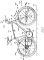
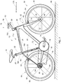
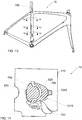
- FIG. 1 shows a bicycle 10 having a frame assembly 12.
- Bicycle 10 includes a seat 16 and handlebars 18 that are attached to frame assembly 12.
- a seat post 20 is connected to seat 16 and slidably engages an adjustable seat tube 22 of frame assembly 12.
- a top tube 24 and a down tube (bottom tube) 26 extend forwardly from adjustable seat tube 22 to a head tube 28 of frame 712.
- Handlebars 18 are connected to a stem or steer tube 30 that passes through head tube 28 and is connected or integrally formed with a fork crown 32.
- Handlebar 18 may include a stem that is constructed to slidably engage an interior cavity of steer tube 30.
- Frame assembly 12 and adjustable seat tube 22 can be formed of metal-type materials, such as aluminum-type materials, carbon fiber materials, and/or materials that are sufficiently formable and robust enough to support the rider of bicycle 10.
- Fork assembly 14 includes a pair of fork blades or fork legs 34 that extend from generally opposite ends of fork crown 32 and are constructed to support a front wheel assembly 36 at an end thereof or dropout 38. Dropouts 38 engage generally opposite sides of an axle 40 constructed to engage a hub 42 of front wheel assembly 36. A number of spokes 44 extend from hub 42 to a rim 46 of front wheel assembly 36. A tire 48 is engaged with rim 46 such that rotation of hub 42 and rim 46, relative to fork legs 34, rotates tire 48. Fork assembly 14 can be secured to the head tube 28 by steer cap 733.
- Bicycle 10 includes a front brake assembly 50 having an actuator 52 attached to handlebars 18 and a pair of brake pads 53 positioned on generally opposite sides of front wheel assembly 36. Brake pads 53 can be constructed to engage a brake wall 54of rim 46 thereby providing a stopping or slowing force to front wheel assembly 36.
- a rear wheel assembly 56 includes a brake assembly 58 similar to front wheel brake assembly 50 but it is appreciated that one or both of front and rear wheel brake assemblies 50, 58 could be provided in other brake configurations such as a disk brake assembly wherein a rotor and a caliper are positioned proximate one or more of front wheel axle 40 or a rear axle 64, respectively.
- a rear wheel 66 is positioned generally concentrically about rear axle 64.
- a pair of seat stays 62, 68 ( FIG. 2 ) and a pair of chain stays 70, 71 ( FIG. 2 ) extend rearward relative to adjustable seat tube 22 and offset rear axle 64 from a crankset 72.
- Crankset 72 includes a set of pedals 74 that is operationally connected to a flexible drive member such as a chain 76 via one or more variable diameter chain gears or a chain ring or sprocket 78.
- Rotation of chain 76 communicates a drive force to a gear cluster 80 positioned proximate rear axle 64.
- Gear cluster 80 is generally concentrically orientated with respect to rear axle 64 and includes a number of variable diameter gears.
- Gear cluster 80 is operationally connected to a hub 82 of rear wheel 66.
- a number of spokes 84 extend radially between hub 82 and a rim 86 of rear wheel 66 of rear wheel assembly 56.
- rider operation of pedals 74 drives chain 76 thereby driving rear wheel 66 which in turn propels bicycle 10.
- Fork assembly 14 is constructed to support a forward end 88 of bicycle 10 above a ground surface 90.
- Handlebar 18 is connected to frame 712 and fork assembly 14 such that operator manipulation of handlebar 18 is communicated to fork assembly 14 to facilitate rotation of front wheel assembly36 relative to frame assembly 12 along a longitudinal axis, indicated by arrow 175, of bicycle 10.
- a longitudinal plane in the direction of arrow 175 can divide the bicycle 10 into a right-side and a left side from the perspective of a rider sitting on saddle 16 and facing forward end 88. As is commonly understood, such manipulation of handlebar 18 steers bicycle 10 during riding.
- bicycle 10 shown in FIG. 1 is merely exemplary of a number of bicycle configurations. That is, whereas bicycle 10 is shown as what is commonly understood as a street or road bike, it is appreciated that the present invention is applicable to a number of bicycle configurations including those bicycles with more aggressive suspension systems commonly found in off-road or mountain bike frame configurations, and/or hybrids, cross-over or multi-purpose bicycle frame configurations.
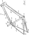
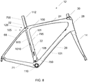
- top tube 24 and seat stays 68 extend in a fairly continuous manner to form an upper frame member 100 that extends from head tube 28 to a pair of dropouts 102, 103 that support rear axle 64.
- Upper frame member 100 can be formed as one piece and/or assembled from a distinct top tube 24, seat stays 68, and/or an optional lug 104 that is disposed between the top tube 24 and the seat stays 68. It is appreciated that seat stays 62, 68 and top tube 24 of upper frame member 100 could be formed as a unitary structure, a number of discrete permanently connected elements, or connected to one another via an optional lug 104 associated with an overlap area 105 of adjustable seat tube 22 and upper frame member 100.
- down tube 26, bottom bracket 110, and chain stays 70, 71 whose assemblies collectively define a lower frame member that extends from head tube 28 to one or more dropouts 102, 103 could be formed as a unitary assembly wherein bottom bracket 110 is formed with down tube 26 or chain stays 70, 71, or an assembly wherein the chain stays 70, 71 and down tube 26 can be permanently affixed to a discrete bottom bracket lug or simply bottom bracket 110.
- bicycle 10 includes a forward frame triangle that is a generally defined by the triangular shape of the direction of extension of the seat tube, the top tube, and the down tube of frame assembly 12 regardless of the methodology or number of discrete elements used to form the frame assembly.
- adjustable seat tube 22 includes a first end 108 that is secured to bottom bracket 110 of bicycle frame 712 and a second end 112 that extends in a generally upward direction beyond the location of the lug or overlap area 105 with upper frame member 100.
- Seat post 20 FIG. 1
- a passive pivot assembly 120 can connect an upper portion of adjustable seat tube 22 to bicycle frame assembly 12 proximate overlap area 105 such that more of adjustable seat tube 22 extends between pivot assembly 120 and bottom bracket 110 than extends in an upward direction relative to the intersection of adjustable seat tube 22 and upper frame member 100.
- Passive pivot assembly 120 can complete the linkage between upper frame member 100, which can include top tube 24 and the structures associated with seat stays 62, 68.
- a lower end of adjustable seat tube 22 can be secured to lower frame member 101, which can include the down tube 26 and bottom bracket 110 and one of more chain stays 70, 71.
- adjustable seat tube 22, top tube 24 and down tube 25 collectively generally define the forward triangle of frame assembly 12.
- Frame assembly 12 has a fairly robust and stable feel during use but is also constructed to provide impact dampening performance in a manner that does not allow changing of the relative connection points of any of the respective members of the forward frame triangle. As described further below with respect to FIG.
- the non-bonded rigid yet pivotable connection of seat tube 22 with upper frame member 100 allows deflection of adjustable seat tube 22 in a vertical plane and in a direction along the longitudinal length of the adjustable seat tube 22 so as to allow the frame assembly 12 to provide a limited degree of suspension performance or vertical compliance without altering the orientation of the connection points of any of the frame members relative to one another.
- the adjustable seat tube 22 can bend, absorbing the bumps thereby providing a more comfortable ride.
- the adjustable seat tube 22 seat tube can be adjusted by an adjustment feature such as a stiffener.
- a plate can be secured to the seat tube 22 in an adjustable manner.
- the plate can be exchanged for a plate with a different stiffness.
- a top of a unitary seat tube can be coupled to the bottom of the seat tube by a turnbuckle.
- a preloading i.e., the pressure on the bearing assemblies, for example, applied by the torqueing of the pivot fasteners
- the passive pivot assembly 120 can be increased to decrease compliance of the seat tube 22; and the preloading of the passive pivot assembly 120 can be decreased to increase compliance of the seat tube 22.
- a portion of the seat tube can also be connected statically to the top tube and/or the pair of seat stays.
- the seat tube can be made of two portions that can be coupled in various configurations by the user.
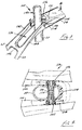
- overlap area 105 can include a passage 130 that is shaped to allow adjustable seat tube 22 to pass therethrough.
- An opening 132 ( FIG. 5 ) is formed laterally through adjustable seat tube 22 and shaped to rotationally cooperate with pivot assembly 120.
- adjustable seat tube 22 can merely pass over an axis or longitudinal area associated with one or more of the top tube, the seat stays, and/or a fabrication lug being formed therebetween. It is envisioned that the seat tube could be perforated or otherwise contoured to pass generally around the more horizontal structure of the top tube and/or the seat stays associated with upper frame member 100.
- the seat tube could pass rearward relative to the closed structure of top tube 24 so as to be positioned in the space generally flanked by the seat stays.
- Each configuration allows limited passive pivoting between seat stays 70, 71 and the adjacent structure of upper frame member100 of bicycle frame assembly 12.
- passage 130 can be bounded on a forward side 131 by an end wall associated with top tube 24 or a portion of the respective frame lug 104.
- a first optional gasket 134 is disposed between forward side 131 of overlap area 105 and top tube 24 and generally surrounds a forward side 136, and opposite lateral sides 138, 140 of adjustable seat tube 22.
- Optional gasket 134 prevents moisture and/or dirt and/or debris from entering the pivot area associated with passage 130 and the passage of adjustable seat tube 22 therethrough but does not otherwise interfere with the flexion of adjustable seat tube 22 during use of bicycle 10 as described further below with respect to FIG. 6 .
- Passage 130 can be bounded on opposite lateral sides by side walls 142, 144 of upper frame member 100.
- An optional rear web wall 146 can complete the definition of passage 130 such that upper frame member 100 completely surrounds adjustable seat tube 22 with web wall 146 extending laterally between seat stays 62, 68.
- pivot assembly 120 can include a first bolt or other fastener 150, a second bolt or other fastener 152, a guide sleeve 154, and first and second bearings or bushings 156, 158.
- Each of fasteners 150, 152 can include a threaded portion 160, a stem portion 162, and a head portion 164. The radial diameter of each fastener 150, 152 can gradually increase from the respective threaded portion 160 to the stem portion 162 to the head portion 164.
- head portions 164 can include a drive surface 166 that is shaped to cooperate with a driving tool, such as a hex driver or the like for securing each of first and second fasteners 150, 152 relative to pivot assembly 120.
- a driving tool such as a hex driver or the like for securing each of first and second fasteners 150, 152 relative to pivot assembly 120.
- driving surface 166 could have any number of shapes and/or be provided on a radial exterior surface of the corresponding fastener 150, 152.
- one of fasteners 150, 152 could formed integrally with sleeve 154 such that operation of one respective fastener secures pivot assembly 120 relative to bicycle frame assembly 12.
- Each bushing 156, 158 can include an outer radial surface 170, an inner radial surface 172, an outboard lateral surface 174, and an inboard lateral surface 176.
- the inboard and outboard lateral directions associated with surfaces 174, 176 of each bushing 156, 158 refers to the orientation of surfaces 170, 174 relative to a longitudinal vertical plane that contains longitudinal axis 175 of bicycle 10 and the relative position of the respective surfaces and/or structures relative to the same.
- surfaces 176 of bushings 156, 158 are nearer a longitudinal axis, indicated by line 178, of upper frame member 100.
- surfaces 174 are further outboard and surfaces 176 are further inboard relative to one another and longitudinal axis 178 of upper frame member 100 along a longitudinal axis, indicated by line 180, of pivot assembly 120.
- the longitudinal axis 180 of pivot assembly 120 is oriented in a crossing direction relative to, and is normal to, longitudinal axis 178 of upper frame member 100.
- a first opening 184 and the second opening 186 can be formed in each of the respective sidewalls 142, 144 of upper frame member 100 and centered along axis 180 of pivot assembly 120.
- a seat 188 can extend circumferentially about at least one of openings 184, 186 in the lateral outboard facing surface of the respective sidewall142, 144.
- Seat 188 can be defined by a lip 190 that extends circumferentially about the corresponding opening 184, 186 and can be shaped to cooperate with sleeve 154 and a corresponding bushing 156, 158.
- Sleeve 154 can include a stem portion 194, the head portion 196, and an opening 198 formed therethrough. Sleeve 154 can be constructed to slidably cooperate with openings 184, 186 in a direction aligned with axis 180. When assembled, head portion 196 of sleeve 154 traverses an overlapping area between opening 184 and a seat 199 associated with opening 132 of adjustable seat tube 22 as well as opening 200 associated with optional gasket 134.
- Optional gasket 134 can include a second opening 202 that, when assembled, is also concentrically oriented with respect axis 180 of pivot assembly 120 and cooperates with the other of fasteners 150, 152.
- Opening 132 of adjustable seat tube 22 circumferentially cooperates with stem portion 194 of sleeve 154 when the longitudinal axis of opening 132 is aligned axis 180 of pivot assembly 120.
- the axis of opening 132 of adjustable seat tube 22 can be formed along a plane, indicated by line 204 that can be offset in a forward direction relative to longitudinal axis 175 of bicycle 10 and with respect to a longitudinal axis 206 of adjustable seat tube 22.
- Threaded portions 160 of each fastener 150, 152 can operatively cooperate with a threaded surface 210 ( FIG. 4 ) formed on an inner radial surface of sleeve 154.
- Bushings 156, 158 can rotatably cooperate with stem portion 162 of each of fasteners 150,152 and cooperate with seats 188 defined by upper frame member 100.
- pivot assembly 120 can include another optional gasket 214 that cooperates with the laterally outboard directed sides of pivot assembly 120.
- Gasket 214 can includes a first arm 216 and a second arm 218 that extend in a generally upward direction relative to a web wall 220.
- each arm 216, 218 can include a lip 221 that is shaped to snuggly cooperate with a radially outboard directed surface of head portion 164 of a respective fastener 150, 152.
- the upper frame member 100 can include a recess 222 that is shaped to mimic the shape of gasket 214 such that when assembled, gasket 214 provides a generally smooth contour along the exterior surface of upper frame member 100 associated with pivot assembly 120.
- pivot assembly 120 When assembled, pivot assembly 120 can provide a secure connection between upper frame member 100 and adjustable seat tube 22 and does so in a manner that prevents lateral, longitudinal, and vertical movement of adjustable seat tube 22 relative to upper frame member 100 but allows rotation of adjustable seat tube 22 about axis 180 associated with opening 132 which is collinear with pivot assembly 120 relative to upper frame member 100.
- Such a connection allows only flexion or flexing movement of seat tube 22 relative to the other structural members of bicycle frame assembly 12 during use of bicycle 10.
- adjustable seat tube 22 could include a passage like passage 130 or otherwise be contoured so that the seat tube passed around the top tube/seat stays/lug and/or such that the top tube/seat stays/lug pass through the seat tube.
- Still another alternative includes connecting the seat stays to the upper frame member or top tube at a location forward of the seat tube such that the seat tube would be positioned in an area generally flanked by the seat stays. Referring to FIG.
- axis 180 could be oriented to intersect axis 206 or offset in a rearward direction relative thereto so as to alter the deflection performance of adjustable seat tube 22 and/or to better suit the preferences of a given rider or class of users.
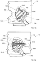
- adjustable seat tube 22 maintains a generally "at rest” configuration as represented by adjustable seat tube 22 shown in FIG. 6 .
- the adjustable seat tube 22 can have a fairly linear at rest orientation. Understandably, during normal use, some initial deflection of adjustable seat tube 22 may occur depending on the weight and preferred orientation of the rider during normal use over relatively smooth terrain.
- an impact event indicated by arrow 230, a downward and rearward bending moment is imparted to adjustable seat tube 22 by the interaction of the rider with the rear portion of a saddle, which is commonly offset to the rear of the longitudinal centerline 206 of adjustable seat tube 22.
- Such loading of the seat tube allows seat tube 22 to pivot in a passive manner about pivot assembly 120 and results in a rearward deflection of an upper portion 232 of adjustable seat tube 22 positioned above pivot assembly 120 and a forward deflection of a lower portion 234 of adjustable seat tube 22 that is positioned between pivot assembly 120 and bottom bracket 110 relative to the at-rest orientation.
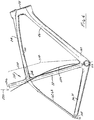
- adjustable seat tube 22 The deflection of adjustable seat tube 22 relative to upper frame member 100 and lower frame member 101 is shown graphically in FIG. 6 by line 236.
- Such a configuration allows near the entirety of adjustable seat tube 22 to deflect from an at rest position to a "bent" orientation, represented by line 236 to improve the vertical compliance of frame assembly 12.
- Supporting an upper end of adjustable seat tube 22 proximate the intersection of adjustable seat tube 22 with upper frame member 100 provides a fairly rigid feel of frame assembly 12 during all riding conditions but mitigates the communication of undampened travel surface discontinuities to the rider via rider interaction with the bicycle seat. Such performance improves rider comfort and decreases rider discomfort commonly associated with extended rides.
- adjustable seat tube 22 deflects no more than 15 degrees from an at rest orientation and more preferably, adjustable seat tube 22 deflects no more than 7 degrees from a rest position in response to rider interaction with seat 16.
- Such a configuration has been shown to provide a desired degree of responsiveness to rider interaction with the bicycle frame and does so in a manner that improves the vertical compliance of the bicycle frame assembly without unduly detracting from the same.
- the greatest deflection value is associated with a deflection that a rider will tolerate and still feel comfortable on the bicycle during most riding conditions to a near unperceivable deflection during most riding conditions.
- frame assembly 12 provides greater longitudinal deflection of the seat tube with comparable lateral stiffness for bicycle frames having similar shapes and with nearly negligible contribution to the overall weight of the bicycle frame assembly. It is further envisioned that the forward and/or rearward orientation of the pivot axis relative to the longitudinal axis of the seat tube can be manipulated to satisfy a wide variety of rider performance preferences and/or to alter the deflection performance of the seat tube. It is further appreciated that the construction of the seat tube can be manipulated to further alter the vertical compliance of the frame assembly while providing a robust bicycle frame assembly.
- bicycle frame assembly 12 provides a bicycle frame having acceptable frame responsiveness with improved vertical compliance for improving rider comfort.
- FIG. 7 a side view of a first embodiment of the bicycle 10 in accordance with an illustrative embodiment of the present invention is shown.
- FIG. 8 a side view of a first embodiment of the frame assembly 12 of FIG. 7 in accordance with an illustrative embodiment is shown.
- FIG. 9 a perspective view of a first embodiment of the frame assembly 12 of FIG. 7 in accordance with an illustrative embodiment is shown.
- FIG. 10 a side view of a frame 712 of the frame assembly 12 of FIG. 7 in accordance with an illustrative embodiment is shown.
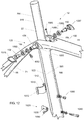
- FIG. 11 a side view of an upper seat mast 790 of the frame assembly 12 of FIG.
- FIG. 12 a perspective view of the passive pivot assembly 120 of the frame assembly 12 of FIG. 7 in accordance with an illustrative embodiment is shown.
- FIG. 13 a side sectioning view of the frame assembly 12 of FIG. 7 in accordance with an illustrative embodiment is shown.
- FIG. 14 a top section view of Section 14-14 of the frame assembly 12 of FIG. 7 in accordance with an illustrative embodiment is shown.
- FIG. 15 a top section view of Section 15-15 of the frame assembly 12 of FIG. 7 in accordance with an illustrative embodiment is shown. Referring to FIG.
- FIG. 16 a top section view of Section 16-16 of the frame assembly 12 of FIG. 7 in accordance with an illustrative embodiment is shown.
- FIG. 17 a top sectioning view of the frame assembly 12 of FIG. 7 in accordance with an illustrative embodiment is shown.
- FIG. 18 a side section view of Section 18-18 of the adjustable seat tube 22 area of the frame assembly 12 of FIG. 7 in accordance with an illustrative embodiment is shown.
- FIG. 19 a side section view of Detail 19 of the frame assembly 12 of FIG. 7 in accordance with an illustrative embodiment is shown.
- FIG. 20 a side section view of Detail 20 of the frame assembly 12 of FIG. 7 in accordance with an illustrative embodiment is shown.
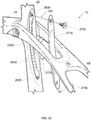
- the adjustable seat tube 22 can include an upper seat mast 790 and a lower seat mast 795. At least a portion of the upper seat mast 790 and at least a portion of the lower seat mast 795 can overlap. In one embodiment, an upper adjustment portion 920 of the upper seat mast 790 and a lower adjustment portion 925 of the lower seat mast 795 overlap for at least half of the length of the lower seat mast 795.
- the facing portions of the upper adjustment portion 920 and the lower adjustment portion 925 can generally loosely match each other, that is, a gap 1210 can be located between the upper adjustment portion 920 and the lower adjustment portion 925.
- the passive pivot assembly 120 can be associated with the upper seat mast 790.
- the lower seat mast 795 can be attached to the bottom bracket 110 and the upper frame member 100.
- the frame 712 can also include a mounts 750 associated with the lower seat mast 795.
- the upper seat mast 790 can include a seat post portion 910 for mounting a seat post or saddle.
- the upper mast 790 can include features to prevent contamination in a vertical plane from the back of the bike, for example, gaskets, shrouding, etc.
- a highly compressible gasket can be disposed of in the circumference of the gap 1210 to prevent dirt from entering the gap 1210.
- the mounts 750 can be used to, for example, attach a derailleur, attach a chain keep, or attach a sensor.
- the lower seat mast 795 can be attached only to the bottom bracket 110.
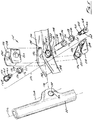
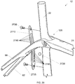
- the passive pivot assembly 120 can include a first shroud 1025, a first fastener 152, a first bearing 1065, a first spacer 158, a guide sleeve 154, a second spacer 156, a second bearing 1060, a second fastener 150, and a second shroud 1027.
- the guide sleeve 154 can be inserted in the opening 132 of the upper seat mast 790.
- An outer race of the first bearing 1065 can sit on a seat 1055.
- An inner race of the first bearing 1065 can be mechanically coupled to the guide sleeve 154 by first spacer 158.
- the first fastener 152 can be inserted through the first bearing 1065 and the first spacer 158 and threaded into the guide sleeve 154.
- the outer race of the first bearing 1065 seats on the seat 1055 and the inner race of the first bearing 1065 couples to the guide sleeve 154, thereby loading the first bearing 1065.
- the preload of the first bearing 1065 can be changed by tightening or loosening the first fastener 152.
- An inner race of the second bearing 1060 can be mechanically coupled to the guide sleeve 154 by second spacer 156.
- the second fastener 150 can be inserted through the second bearing 1060 and the second spacer 156 and threaded into the guide sleeve 154.
- the outer race of the second bearing 1060 seats on a (second, opposite side of seat 1055) seat (not shown) and the inner race of the second bearing 1060 couples to the guide sleeve 154, thereby loading the second bearing 1060.
- the preload of the second bearing 1060 can be changed by tightening or loosening the second fastener 150.
- the first bearing 1065 and the second bearing 1060 can be a bushing.
- An adjustment sleeve 1010 can be located between the at least a portion of the upper seat mast 790 and the at least a portion of the lower seat mast 795 that overlap. In a loosened state of the upper seat mast 790 and a lower seat mast 795, the adjustment sleeve 1010 can slide within the gap 1210.
- the adjustment sleeve 1010 can include finger grips 1012. A user can use the finger grips 1012 to move the adjustment sleeve 1010 higher or lower within the gap.
- the adjustment sleeve 1010 can include a gasket 1510.
- the adjustable seat tube 22 can include an adjustment locking assembly 1020.
- the adjustment locking assembly 1020 can include a nut portion 1035 and insert 1420 associated with the upper seat mast 790 and a bolt portion 1040 and insert 1410 associated with the lower seat mast 795.
- the adjustment locking assembly 1020 can include a gasket 1050.
- the adjustment locking assembly 1020 is tightened, the adjustment sleeve 1010 can be locked between the upper seat mast 790 and the lower seat mast 795.
- the adjustment locking assembly 1020 is loosened, the adjustment sleeve 1010 can be moved within the gap 1210 between the upper seat mast 790 and the lower seat mast 795. The user can move the adjustment sleeve 1010 higher or lower within the gap to change the stiffness of the adjustable seat tube 22.
- the adjustment sleeve 1010 can be made of different materials and thicknesses to provide difference compliance characteristics. In another embodiment, the adjustment sleeve 1010 can be provided in varying lengths to provide difference compliance characteristics. In another embodiment, the adjustment sleeve 1010 can be provided in varying shapes to provide difference compliance characteristics; for example, the surface of the adjustment sleeve 1010 can have ribbing.
- the frame assembly 12 can also include a brake bolt 1092 for mounting a brake.
- the frame assembly 12 can also include a cable stop 1080 and a cable stop mounting bolt 1085.
- the frame assembly 12 can also include an accessory mounting bolt 1090.
- FIG. 21 a perspective assembly view of a second example of the frame assembly 12 is shown.
- FIG. 22 a side sectioning view of the head tube 28 of the second embodiment of the frame assembly 12 of FIG. 21 in accordance with an illustrative embodiment is shown.
- FIG. 23 a front section view Section 23-23 of the head tube 28 of the second embodiment of the frame assembly 12 of FIG. 21 in accordance with an illustrative embodiment is shown.
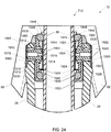
- FIG. 24 a front section view of Detail 24 of the f second embodiment of the frame assembly 12 of FIG. 21 in accordance with an illustrative embodiment is shown. Referring to FIG.
- FIG. 25 a top sectioning view of the head tube 28 of the second embodiment of the frame assembly 12 of FIG. 21 in accordance with an illustrative embodiment is shown.
- FIG. 26 a side section view of Section 26-26 of the head tube 28 of the second embodiment of the frame assembly 12 of FIG. 21 in accordance with an illustrative embodiment is shown.
- FIG. 27 a side section view of Detail 27 of the second embodiment of the frame assembly 12 of FIG. 21 in accordance with an illustrative embodiment is shown.
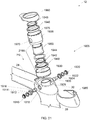
- a headset of frame 712 can include a compliant upper headset assembly 1905 and a lower headset bearing 2122.
- the compliant upper headset assembly 1905 can be located proximate to a top 2220 of the head tube 28.
- the lower headset bearing 2122 can be located proximate to a top 2220 of the head tube 28.
- the lower headset bearing 2122 can be located proximate to a bottom 2230 of the head tube 28.
- the compliant upper headset assembly 1905 can include an upper shroud 1960, a bushing 1948, an upper bearing 1946, an upper cup 1935, a standoff 1950, a thrust washer 1944, a bushing 1942, a lower bearing 1940, a lower cup 1930, a lower shroud 1965, a first retainer 1910, a first spacer 1912, a first bushing 1914, a first pin 1916, a second retainer 1920, a second spacer 1922, a second bushing 1924, and a second pin 1926.
- the bushing 1948 can be a preload spacer or a compression ring.
- the bushing 1948 can be made, for example, of metal.
- the standoff 1950 can be a preload spacer or a compression ring.
- the standoff 1950 can be made, for example, of metal.
- the upper cup 1935 can include a first cup opening 1970 and a second cup opening 1975.
- the first pin 1916 can be inserted in the first cup opening 1970 and the second pin 1926 can be inserted in the second cup opening 1975.
- the inside of the first bushing 1914 sits on the first pin 1916.
- the outside of the first bushing 1914 sits in a first frame opening 1918.
- the inside of the second bushing 1924 sits on the second pin 1926.
- the outside of the second bushing 1924 sits in a second frame opening 1928.
- the upper cup 1935 can rotate fore and aft on first pin 1916 and second pin 1926.
- the lower cup 1930 can be coupled to the upper cup 1935; for example, the lower cup 1930 and the upper cup 1935 can be threaded together.
- the cup 2199 can rotate fore and aft on first pin 1916 and second pin 1926 relative to the head tube 28.
- the cup 2199 can be located at least partially within the head tube 28. Hence, the cup 2199 is gimbaled to the head tube 28.
- the lower bearing 1940 can sit in the lower cup 1930.
- the standoff 1950, the thrust washer 1944, and the bushing 1942 can be associated with the inner race of the lower bearing 1940.
- the bushing 1948 and the upper bearing 1946 can rest on the standoff 1950.
- the steer tube 30 can be inserted through the bushing 1948, the upper bearing 1946, the upper cup 1935, the standoff 1950, the thrust washer 1944, the bushing 1942, the lower bearing 1940, and the lower cup 1930.
- a stem or steer tube cap 733 can be used to lock or secure the compliant upper headset assembly 1905 together.
- the lower headset bearing 2122 can sit on a crown seat 2110 of the crown 32. When the steer tube cap 733 is tightened, the bushing 1948, the upper bearing 1946, the upper cup 1935, the standoff 1950, the thrust washer 1944, the bushing 1942, and the lower bearing 1940 are preloaded.
- the steer tube 30 can flex.
- the steer tube 30 can be made of fiber reinforced plastic, such a carbon fiber in a plastic matrix.
- the flexure of the steer tube 30 can be controlled by the layering of the carbon fiber.
- the steer tube 30 can be designed to flex more in a fore and aft direction as opposed to a side-to-side direction.
- the steer tube 30 is inserted through the cup 2199.
- the cup 2199 can rotate fore and aft on first pin 1916 and second pin 1926.
- the rotatable cup 2199 allows the steer tube 30 to flex more than compared to a headset with fixed bearings.
- the upper bearing 1946 and the lower bearing 1940 allow the rider to rotate the steer tube 30, in order to turn the front wheel, even though the steer tube 30 is inserted through cup 2199.
- the fork 14 can flex more providing improved frame responsiveness with improved vertical compliance for improving rider comfort.
- FIG 28 shows a perspective assembly view of frame assembly 12 including the first and second embodiments.
- the adjustable seat tube 22 increases rider comfort and frame adaptability to riding conditions.
- the compliant upper headset assembly 1905 enables the steer tube 30 to flex more than a static upper headset bearing.
- FIG. 29 a perspective assembly view of a third example of the frame assembly 12 is shown.
- FIG. 30 a second perspective assembly view of the third example of the frame assembly 12 of FIG. 29 is shown.
- FIG. 31 a top sectioning view of the third example of the frame assembly 12 of FIG. 29 is shown.
- FIG. 32 a side section view of Section 32-32 of the passive pivot assembly 120 of the third example of the frame assembly 12 of FIG. 29 is shown.
- FIG. 33 a bottom section view of Section 33-3 of the third example of the frame assembly 12 of FIG. is shown.
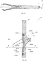
- An adjustment plate 2710 can be coupled to the adjustable seat tube 22.
- the adjustment plate 2710 can include a series of first indents 2740.
- the adjustable seat tube 22 can include a series of second indents 2840.
- the adjustable seat tube 22 can include a first threaded hole 2830 and a second threaded hole 2835.
- the adjustment plate 2710 can be secured to the adjustable seat tube 22 by a first retaining bolt 2730 (associated with the first threaded hole 2830) and a second retaining bolt 2735 (associated with the second threaded hole 2835).
- the adjustment plate 2710 and the adjustable seat tube 22 can be separated by a gap 3010.
- the adjustment plate 2710 and the adjustable seat tube 22 can capture a first object 2720 and a second object 2820.
- the first object 2720 and the second object 2820 can sit in between first indents 2740 and second indents 2840.
- the first object 2720 and the second object 2820 can be a sphere, cylinder or any other shape.
- the user can loosen the adjustment plate 2710 and move the first object 2720 and the second object 2820 to different first indents 2740 and second indents 2840 pairs.
- One, two, three, or more objects can be placed in between first indents 2740 and second indents 2840.
- the first object 2720 and the second object 2820 can be made of metal, elastomer, plastic, fiber reinforce plastic, or any other material.
- a strip of material can be placed in between the adjustment plate 2710 and the adjustable seat tube 22.
- interchangeable stiffening rods, tubes, or inserts can be placed inside the seat tube 22 along at least a portion of the length of the seat tube 22.
- preload on the passive pivot assembly 120 can be increased or decreased to change the compliance (or flexibility) of the seat tube 22.
- any two components so associated can also be viewed as being “operably connected”, or “operably coupled”, to each other to achieve the desired functionality, and any two components capable of being so associated can also be viewed as being “operably couplable”, to each other to achieve the desired functionality.
- operably couplable include but are not limited to physically mateable and/or physically interacting components and/or wirelessly interactable and/or wirelessly interacting components and/or logically interacting and/or logically interactable components.
Landscapes
- Engineering & Computer Science (AREA)
- Mechanical Engineering (AREA)
- Motorcycle And Bicycle Frame (AREA)
- Steering Devices For Bicycles And Motorcycles (AREA)
Claims (7)
- Bicyclette, comprenant :
un triangle de cadre avant comprenant :un tube haut (24) ayant une première extrémité raccordée à un tube de direction (28) et une seconde extrémité ;un tube bas (26) ayant une première extrémité raccordée au tube de direction et une seconde extrémité ;un boîtier de pédalier (110) raccordé à la seconde extrémité du tube bas ; etun mât de siège inférieur (795) s'étendant dans une direction ascendante depuis le boîtier de pédalier jusqu'au tube haut ;un mât de siège supérieur (790) chevauchant au moins partiellement le mât de siège inférieur, dans laquelle le mât de siège supérieur est couplé de façons ajustable et fixe au mât de siège inférieur et le mât de siège supérieur est couplé de façon rotative au triangle de cadre avant à proximité de la seconde extrémité du tube haut ; etun manchon d'ajustement (1010) situé entre le mât de siège inférieur et le mât de siège supérieur,caractérisée en ce que :une portion d'ajustement supérieure (920) du mât de siège supérieur (790) et une portion d'ajustement inférieure (925) du mât de siège inférieur (795) se chevauchent sur au moins la moitié de la longueur du mât de siège inférieur, dans laquelle un espace (1210) est situé entre des portions se faisant face de la portion d'ajustement supérieure et de la portion d'ajustement inférieure,le manchon d'ajustement (1010), le mât de siège inférieur, et le mât de siège supérieur sont configurés de telle sorte que le manchon d'ajustement puisse coulisser à l'intérieur dudit espace, etla bicyclette comprend en outre un ensemble de verrouillage d'ajustement (1020) configuré pour fixer le manchon d'ajustement (1010) à l'intérieur dudit espace. - Bicyclette selon la revendication 1, dans laquelle au moins le mât de siège supérieur est configuré pour fléchir dans une direction longitudinale en réponse à des forces de cyclique.
- Bicyclette selon la revendication 1, comprenant en outre une paire de haubans (62, 98) raccordés au tube haut et s'étendant dans une direction arrière au-delà du triangle de cadre avant.
- Bicyclette selon la revendication 1, dans laquelle le mât de siège supérieur est couplé de façon rotative au triangle de cadre avant par un ensemble pivot (120) à un emplacement plus près d'une selle de bicyclette que le boîtier de pédalier.
- Bicyclette selon la revendication 4, dans laquelle l'ensemble pivot comprend au moins une d'une paire de paliers ou d'une paire de douilles (1060, 1065).
- Bicyclette selon la revendication 1, dans laquelle le manchon d'ajustement est fait d'au moins un d'un métal, élastomère, et d'un plastique renforcé par des fibres.
- Bicyclette selon la revendication 1, dans laquelle le mât de siège inférieur et le mât de siège supérieur sont faits d'un plastique renforcé par des fibres.
Priority Applications (3)
| Application Number | Priority Date | Filing Date | Title |
|---|---|---|---|
| PL16725714T PL3265372T3 (pl) | 2015-05-17 | 2016-05-17 | Rower o regulowanej podatności |
| PL17195292T PL3301004T3 (pl) | 2015-05-17 | 2016-05-17 | Rower o nastawnej odkształcalności |
| EP17195292.2A EP3301004B1 (fr) | 2015-05-17 | 2016-05-17 | Bicyclette de souplesse réglable |
Applications Claiming Priority (3)
| Application Number | Priority Date | Filing Date | Title |
|---|---|---|---|
| US201562162812P | 2015-05-17 | 2015-05-17 | |
| US201562163076P | 2015-05-18 | 2015-05-18 | |
| PCT/US2016/032871 WO2016187197A2 (fr) | 2015-05-17 | 2016-05-17 | Bicyclette à conformité réglable |
Related Child Applications (2)
| Application Number | Title | Priority Date | Filing Date |
|---|---|---|---|
| EP17195292.2A Division-Into EP3301004B1 (fr) | 2015-05-17 | 2016-05-17 | Bicyclette de souplesse réglable |
| EP17195292.2A Division EP3301004B1 (fr) | 2015-05-17 | 2016-05-17 | Bicyclette de souplesse réglable |
Publications (2)
| Publication Number | Publication Date |
|---|---|
| EP3265372A2 EP3265372A2 (fr) | 2018-01-10 |
| EP3265372B1 true EP3265372B1 (fr) | 2019-08-21 |
Family
ID=57276570
Family Applications (2)
| Application Number | Title | Priority Date | Filing Date |
|---|---|---|---|
| EP17195292.2A Active EP3301004B1 (fr) | 2015-05-17 | 2016-05-17 | Bicyclette de souplesse réglable |
| EP16725714.6A Active EP3265372B1 (fr) | 2015-05-17 | 2016-05-17 | Bicyclette à conformité réglable |
Family Applications Before (1)
| Application Number | Title | Priority Date | Filing Date |
|---|---|---|---|
| EP17195292.2A Active EP3301004B1 (fr) | 2015-05-17 | 2016-05-17 | Bicyclette de souplesse réglable |
Country Status (6)
| Country | Link |
|---|---|
| US (4) | US10086899B2 (fr) |
| EP (2) | EP3301004B1 (fr) |
| DK (1) | DK3265372T3 (fr) |
| ES (2) | ES2750620T3 (fr) |
| PL (2) | PL3265372T3 (fr) |
| WO (1) | WO2016187197A2 (fr) |
Cited By (1)
| Publication number | Priority date | Publication date | Assignee | Title |
|---|---|---|---|---|
| US10919592B2 (en) | 2018-04-06 | 2021-02-16 | Specialized Bicycle Components, Inc. | Bicycle with compliant seat post interface |
Families Citing this family (4)
| Publication number | Priority date | Publication date | Assignee | Title |
|---|---|---|---|---|
| KR102328647B1 (ko) * | 2019-04-08 | 2021-11-17 | 서명진 | 자전거용 프레임 |
| USD908542S1 (en) * | 2019-07-19 | 2021-01-26 | Cycling Sports Group, Inc. | Bicycle flex stay |
| US20220340230A1 (en) * | 2019-09-06 | 2022-10-27 | Lauf Forks Hf. | A low travel rear wheel suspension system for a bike |
| USD1045677S1 (en) * | 2023-05-05 | 2024-10-08 | Shenzhen Kixin Electronics Co., Ltd | Bicycle frame |
Family Cites Families (80)
| Publication number | Priority date | Publication date | Assignee | Title |
|---|---|---|---|---|
| US527404A (en) | 1894-10-16 | Charles byrne | ||
| US499707A (en) | 1893-06-20 | Prank h | ||
| US640913A (en) | 1899-04-11 | 1900-01-09 | John S Hull | Device for capping cans. |
| US673661A (en) * | 1899-12-04 | 1901-05-07 | William Walker Reid | Cycle-frame. |
| US973217A (en) | 1910-05-03 | 1910-10-18 | James H Sager | Shock-absorber. |
| US1148170A (en) | 1912-11-12 | 1915-07-27 | Roberto Incerti | Frame for cycles and the like. |
| FR836294A (fr) * | 1938-04-07 | 1939-01-13 | Bicyclette ou véhicule léger analogue | |
| US2283671A (en) | 1939-03-16 | 1942-05-19 | Finlay Albert Daley | Spring suspension device for cycles and motorcycles |
| FR1003351A (fr) * | 1949-12-16 | 1952-03-17 | Perfectionnements au mécanisme de direction des vélocipèdes | |
| US3030124A (en) | 1959-01-19 | 1962-04-17 | American Mach & Foundry | Bond joints for a bicycle frame |
| US3966230A (en) | 1974-03-28 | 1976-06-29 | Teledyne, Inc. | Bicycle frame |
| USD244593S (en) | 1975-11-06 | 1977-06-07 | The Murray Ohio Manufacturing Company | Bicycle frame |
| US4577879A (en) | 1983-09-19 | 1986-03-25 | Vereyken Franciscus A | Bicycle |
| USD284646S (en) | 1984-04-19 | 1986-07-15 | GT BMX Products, Inc. | Bicycle frame |
| USD292074S (en) | 1985-03-04 | 1987-09-29 | American Bicycle Manufacturing Company | Bicycle frame |
| US4938733A (en) | 1988-01-06 | 1990-07-03 | Sram Corporation | Bicycle gear shifting method and apparatus |
| USD308500S (en) | 1988-04-25 | 1990-06-12 | Uni-Bmx, Inc. | Bicycle frame |
| USD311508S (en) | 1988-06-24 | 1990-10-23 | Huffy Corporation | Bicycle frame |
| US5188003A (en) | 1992-01-03 | 1993-02-23 | Equi-Cycle Corporation | Power assist device for a drive mechanism |
| USD343147S (en) | 1992-03-18 | 1994-01-11 | The Murray Ohio Manufacturing Company | Bicycle frame |
| JPH061175U (ja) | 1992-06-17 | 1994-01-11 | 宮田工業株式会社 | 自転車用フレーム |
| EP0586754A1 (fr) * | 1992-09-10 | 1994-03-16 | Jörg Ziegler | Cadres pour véhicules à voie unique, en particulière bicyclettes |
| FR2704826B1 (fr) * | 1993-05-06 | 1995-10-06 | Corniglion Louis | Cadre de cycle deformable a articulations et suspensions. |
| JPH0853092A (ja) * | 1994-08-11 | 1996-02-27 | Mizuno Corp | 自転車用frp製前フォーク |
| US5498013A (en) | 1994-12-12 | 1996-03-12 | Hwang; Chiuon T. | Bicycle frame having shock absorbing device |
| US5803476A (en) | 1995-08-25 | 1998-09-08 | Gt Bicycles, Inc. | Composite bicycle frame and method of manufacturing |
| US5876054A (en) | 1995-08-25 | 1999-03-02 | Gt Bicycles, Inc. | Composite bicycle frame and method of manufacture |
| US5797613A (en) | 1996-06-14 | 1998-08-25 | Gt Bicycles, Inc. | Bicycle flex joint |
| USD384307S (en) | 1996-07-03 | 1997-09-30 | Trek Bicycle Corporation | Bicycle frame |
| US5971416A (en) | 1996-08-05 | 1999-10-26 | Hsiung; Kao Fu | Bicycle shock absorbing arrangement |
| US5725225A (en) * | 1997-02-03 | 1998-03-10 | Lai; Yen-Pin | Shock-absorbing assembly of bicycle |
| USD411145S (en) | 1998-03-18 | 1999-06-22 | Huffy Corporation | Bicycle frame |
| US5975550A (en) | 1998-03-27 | 1999-11-02 | Schonfeld; Carl W. | Torsional shock absorber for bicycle |
| US6109637A (en) | 1998-04-10 | 2000-08-29 | Great American Bicycle Co., Llc | Bicycle frame with self-damped spring action seat stays |
| US6318744B1 (en) | 1998-05-26 | 2001-11-20 | Donald Eugene Lester | Trianglar bicycle frame |
| US6755432B2 (en) | 1998-08-18 | 2004-06-29 | Paul Muser | Suspension system for bicycle |
| US6076845A (en) | 1998-09-24 | 2000-06-20 | Schwinn Cycling & Fitness Inc. | Rear suspension for a bicycle having a flexible chain stay |
| US6206396B1 (en) | 1998-10-15 | 2001-03-27 | Ezryd, Llc | Cycle incorporating shock absorber |
| AU137821S (en) | 1998-11-27 | 1999-07-20 | A bicycle frame | |
| USD419110S (en) | 1999-05-14 | 2000-01-18 | Murray, Inc. | Design for bicycle frame |
| USD418778S (en) | 1999-05-14 | 2000-01-11 | Murray, Inc. | Bicycle frame |
| USD419111S (en) | 1999-05-14 | 2000-01-18 | Murray, Inc. | Bicycle frame |
| GB2366263B (en) * | 2000-08-25 | 2002-07-10 | Jeffery Ernest Amos | Bicycle frame |
| US20020125679A1 (en) | 2001-03-07 | 2002-09-12 | Wu-Chung Jung | Device disposed on a bicycle for generating an alerting light when the wheels of the bicycle rotate |
| DE10128676B4 (de) | 2001-06-13 | 2014-03-13 | Storck Bicycle Gmbh | Fahrradrahmen |
| NO314791B1 (no) | 2001-09-28 | 2003-05-26 | Ole Martin Noer | Tyverisikret sykkel |
| US6892604B2 (en) | 2001-12-13 | 2005-05-17 | Cane Creek Cycling Components, Inc. | Headset spacer unit and steering assembly equipped therewith |
| US6659487B1 (en) | 2002-01-18 | 2003-12-09 | Tony S. Raco | Flexible bike frame |
| JP4116812B2 (ja) * | 2002-04-22 | 2008-07-09 | 本田技研工業株式会社 | 自転車用車体フレーム構造 |
| WO2004074082A1 (fr) | 2003-02-14 | 2004-09-02 | Ricardo Perez | Cadre de bicyclette a suspension passive arriere |
| USD503662S1 (en) | 2004-02-27 | 2005-04-05 | Magic Cycle Industrial Co., Ltd. | Bicycle frame |
| US7380808B2 (en) | 2004-12-03 | 2008-06-03 | Specialized Bicycle Components, Inc. | Bicycle wheel support with vibration isolation |
| US20060225531A1 (en) | 2005-03-18 | 2006-10-12 | Specialized Bicycle Components, Inc. | Clamp for a composite steering interface for a bicycle |
| US7314226B2 (en) | 2005-07-28 | 2008-01-01 | Yu-Tu Hsu | Folding bicycle |
| FR2898577B1 (fr) | 2006-03-15 | 2009-02-13 | Cycles Lapierre Soc Par Action | Perfectionnement a une suspension arriere d'un vehicule |
| US20070228689A1 (en) | 2006-03-31 | 2007-10-04 | Chun-Hung Lin | Bicycle frame tube structure for enhancing the rigidity of the bicycle frame |
| US7503576B1 (en) * | 2006-08-07 | 2009-03-17 | Answer Products, Inc. | Molded assembly to combine a steering tube made of resin blended with carbon fiber composites and a crown made of aluminum for use in a two wheeled vehicle fork assembly |
| USD548141S1 (en) | 2006-09-12 | 2007-08-07 | Currie Technologies, Inc. | Mountain electric bicycle |
| US7837213B2 (en) | 2007-04-16 | 2010-11-23 | Trek Bicycle Corporation | Bicycle rear wheel suspension system |
| US7591475B1 (en) | 2007-05-25 | 2009-09-22 | Craig Calfee | Simplified rear suspension for a bicycle or the like |
| US20080310783A1 (en) * | 2007-06-12 | 2008-12-18 | Chin Haur Industry Co., Ltd. | Bearing assembly for a steering apparatus of a bicycle |
| DE202007014551U1 (de) * | 2007-10-17 | 2009-03-12 | Merida & Centurion Germany Gmbh | Fahrradrahmen |
| TW200944422A (en) | 2008-04-24 | 2009-11-01 | Giant Mfg Co Ltd | Bike with rigid damping effect |
| US20100007113A1 (en) | 2008-07-11 | 2010-01-14 | David Earle | Rear suspension system for bicycles |
| US8103812B2 (en) | 2009-12-10 | 2012-01-24 | Wei-Hua Lu | Electronic system |
| FR2954266B1 (fr) * | 2009-12-21 | 2011-12-23 | Look Cycle Int | Jeu de direction de cycle a goupille et cycle comportant un tel jeu de direction |
| FR2958261B1 (fr) * | 2010-04-01 | 2012-11-09 | Matra Mfg & Services | Ensemble de direction pour deux-roues |
| WO2011126862A1 (fr) | 2010-04-07 | 2011-10-13 | Specialized Bicycle Components, Inc. | Tube de selle de bicyclette |
| US20110318140A1 (en) | 2010-06-24 | 2011-12-29 | Wen-Yao Chang | Height adjustment ring spacer |
| US20120061941A1 (en) | 2010-09-13 | 2012-03-15 | Volagi, LLC | Bicycle frames and bicycles |
| USD637526S1 (en) | 2010-09-13 | 2011-05-10 | Volagi, LLC | Bicycle frame |
| US8857841B2 (en) | 2011-01-05 | 2014-10-14 | Trek Bicycle Corporation | Bicycle frame with passive seat tube pivot joint |
| US8408574B2 (en) | 2011-04-14 | 2013-04-02 | Specialized Bicycle Components, Inc. | Modular trailing edge for bicycle stem |
| CN102556249B (zh) * | 2012-02-21 | 2014-06-04 | 刘烈祥 | 一种自行车车架 |
| US8807585B2 (en) * | 2012-05-04 | 2014-08-19 | Arc Bikes Llc | Seat tube assembly for a bicycle or the like |
| WO2015065514A1 (fr) * | 2013-03-15 | 2015-05-07 | Huber Chris | Dispositif d'accouplement de cadre de vélo pour permettre une flexion |
| US9828054B2 (en) * | 2015-02-24 | 2017-11-28 | Specialized Bicycle Components, Inc. | Bicycle with compliant seat post interface |
| US10150530B2 (en) * | 2015-05-21 | 2018-12-11 | Trek Bicycle Corporation | Rigid frame with high-compliance seat tube and internal cable routing |
| CN213384671U (zh) * | 2020-09-08 | 2021-06-08 | 重庆万鑫康园农业发展有限公司 | 一种手划船的可调摇臂 |
| CN213199948U (zh) * | 2020-09-15 | 2021-05-14 | 冯杏军 | 共享座位自行车 |
-
2016
- 2016-05-17 ES ES16725714T patent/ES2750620T3/es active Active
- 2016-05-17 DK DK16725714T patent/DK3265372T3/da active
- 2016-05-17 PL PL16725714T patent/PL3265372T3/pl unknown
- 2016-05-17 WO PCT/US2016/032871 patent/WO2016187197A2/fr active Application Filing
- 2016-05-17 ES ES17195292T patent/ES2708818T3/es active Active
- 2016-05-17 EP EP17195292.2A patent/EP3301004B1/fr active Active
- 2016-05-17 PL PL17195292T patent/PL3301004T3/pl unknown
- 2016-05-17 EP EP16725714.6A patent/EP3265372B1/fr active Active
- 2016-05-17 US US15/156,495 patent/US10086899B2/en active Active
-
2018
- 2018-09-28 US US16/145,626 patent/US10351192B2/en active Active
-
2019
- 2019-06-26 US US16/452,744 patent/US10676145B2/en active Active
-
2020
- 2020-06-09 US US16/896,279 patent/US11242111B2/en active Active
Non-Patent Citations (1)
| Title |
|---|
| None * |
Cited By (2)
| Publication number | Priority date | Publication date | Assignee | Title |
|---|---|---|---|---|
| US10919592B2 (en) | 2018-04-06 | 2021-02-16 | Specialized Bicycle Components, Inc. | Bicycle with compliant seat post interface |
| US11851125B2 (en) | 2018-04-06 | 2023-12-26 | Specialized Bicycle Components, Inc. | Bicycle with compliant seat post interface |
Also Published As
| Publication number | Publication date |
|---|---|
| ES2750620T3 (es) | 2020-03-26 |
| US20200298921A1 (en) | 2020-09-24 |
| EP3265372A2 (fr) | 2018-01-10 |
| US11242111B2 (en) | 2022-02-08 |
| US20160332687A1 (en) | 2016-11-17 |
| US20190031273A1 (en) | 2019-01-31 |
| EP3301004B1 (fr) | 2018-12-19 |
| EP3301004A1 (fr) | 2018-04-04 |
| ES2708818T3 (es) | 2019-04-11 |
| WO2016187197A3 (fr) | 2017-02-09 |
| US10086899B2 (en) | 2018-10-02 |
| PL3265372T3 (pl) | 2020-03-31 |
| WO2016187197A2 (fr) | 2016-11-24 |
| PL3301004T3 (pl) | 2019-06-28 |
| US20190344851A1 (en) | 2019-11-14 |
| US10676145B2 (en) | 2020-06-09 |
| US10351192B2 (en) | 2019-07-16 |
| DK3265372T3 (da) | 2019-10-28 |
Similar Documents
| Publication | Publication Date | Title |
|---|---|---|
| EP3265373B1 (fr) | Cadre rigide à tube de selle d'une grande souplesse et acheminement interne des câbles | |
| US11242111B2 (en) | Adjustable compliance bicycle | |
| US10328991B2 (en) | Bicycle frame with passive seat tube pivot joint | |
| EP2569213B1 (fr) | Cadre de bicyclette | |
| US9334010B2 (en) | Motorcycle handlebar with shock absorber | |
| EP2343232B1 (fr) | Tige de selle de bicyclette à suspension | |
| US20240227978A9 (en) | Fork arch |
Legal Events
| Date | Code | Title | Description |
|---|---|---|---|
| STAA | Information on the status of an ep patent application or granted ep patent |
Free format text: STATUS: THE INTERNATIONAL PUBLICATION HAS BEEN MADE |
|
| PUAI | Public reference made under article 153(3) epc to a published international application that has entered the european phase |
Free format text: ORIGINAL CODE: 0009012 |
|
| STAA | Information on the status of an ep patent application or granted ep patent |
Free format text: STATUS: REQUEST FOR EXAMINATION WAS MADE |
|
| 17P | Request for examination filed |
Effective date: 20171005 |
|
| AK | Designated contracting states |
Kind code of ref document: A2 Designated state(s): AL AT BE BG CH CY CZ DE DK EE ES FI FR GB GR HR HU IE IS IT LI LT LU LV MC MK MT NL NO PL PT RO RS SE SI SK SM TR |
|
| AX | Request for extension of the european patent |
Extension state: BA ME |
|
| STAA | Information on the status of an ep patent application or granted ep patent |
Free format text: STATUS: EXAMINATION IS IN PROGRESS |
|
| 17Q | First examination report despatched |
Effective date: 20180724 |
|
| DAV | Request for validation of the european patent (deleted) | ||
| DAX | Request for extension of the european patent (deleted) | ||
| GRAP | Despatch of communication of intention to grant a patent |
Free format text: ORIGINAL CODE: EPIDOSNIGR1 |
|
| STAA | Information on the status of an ep patent application or granted ep patent |
Free format text: STATUS: GRANT OF PATENT IS INTENDED |
|
| INTG | Intention to grant announced |
Effective date: 20190321 |
|
| GRAS | Grant fee paid |
Free format text: ORIGINAL CODE: EPIDOSNIGR3 |
|
| GRAA | (expected) grant |
Free format text: ORIGINAL CODE: 0009210 |
|
| STAA | Information on the status of an ep patent application or granted ep patent |
Free format text: STATUS: THE PATENT HAS BEEN GRANTED |
|
| AK | Designated contracting states |
Kind code of ref document: B1 Designated state(s): AL AT BE BG CH CY CZ DE DK EE ES FI FR GB GR HR HU IE IS IT LI LT LU LV MC MK MT NL NO PL PT RO RS SE SI SK SM TR |
|
| REG | Reference to a national code |
Ref country code: GB Ref legal event code: FG4D |
|
| REG | Reference to a national code |
Ref country code: CH Ref legal event code: EP |
|
| REG | Reference to a national code |
Ref country code: DE Ref legal event code: R096 Ref document number: 602016019002 Country of ref document: DE |
|
| REG | Reference to a national code |
Ref country code: AT Ref legal event code: REF Ref document number: 1169430 Country of ref document: AT Kind code of ref document: T Effective date: 20190915 |
|
| REG | Reference to a national code |
Ref country code: IE Ref legal event code: FG4D |
|
| REG | Reference to a national code |
Ref country code: SE Ref legal event code: TRGR |
|
| REG | Reference to a national code |
Ref country code: DK Ref legal event code: T3 Effective date: 20191024 |
|
| REG | Reference to a national code |
Ref country code: NL Ref legal event code: FP |
|
| REG | Reference to a national code |
Ref country code: CH Ref legal event code: NV Representative=s name: VENI GMBH, CH |
|
| REG | Reference to a national code |
Ref country code: LT Ref legal event code: MG4D |
|
| PG25 | Lapsed in a contracting state [announced via postgrant information from national office to epo] |
Ref country code: BG Free format text: LAPSE BECAUSE OF FAILURE TO SUBMIT A TRANSLATION OF THE DESCRIPTION OR TO PAY THE FEE WITHIN THE PRESCRIBED TIME-LIMIT Effective date: 20191121 Ref country code: NO Free format text: LAPSE BECAUSE OF FAILURE TO SUBMIT A TRANSLATION OF THE DESCRIPTION OR TO PAY THE FEE WITHIN THE PRESCRIBED TIME-LIMIT Effective date: 20191121 Ref country code: LT Free format text: LAPSE BECAUSE OF FAILURE TO SUBMIT A TRANSLATION OF THE DESCRIPTION OR TO PAY THE FEE WITHIN THE PRESCRIBED TIME-LIMIT Effective date: 20190821 Ref country code: FI Free format text: LAPSE BECAUSE OF FAILURE TO SUBMIT A TRANSLATION OF THE DESCRIPTION OR TO PAY THE FEE WITHIN THE PRESCRIBED TIME-LIMIT Effective date: 20190821 Ref country code: HR Free format text: LAPSE BECAUSE OF FAILURE TO SUBMIT A TRANSLATION OF THE DESCRIPTION OR TO PAY THE FEE WITHIN THE PRESCRIBED TIME-LIMIT Effective date: 20190821 Ref country code: PT Free format text: LAPSE BECAUSE OF FAILURE TO SUBMIT A TRANSLATION OF THE DESCRIPTION OR TO PAY THE FEE WITHIN THE PRESCRIBED TIME-LIMIT Effective date: 20191223 |
|
| PG25 | Lapsed in a contracting state [announced via postgrant information from national office to epo] |
Ref country code: GR Free format text: LAPSE BECAUSE OF FAILURE TO SUBMIT A TRANSLATION OF THE DESCRIPTION OR TO PAY THE FEE WITHIN THE PRESCRIBED TIME-LIMIT Effective date: 20191122 Ref country code: AL Free format text: LAPSE BECAUSE OF FAILURE TO SUBMIT A TRANSLATION OF THE DESCRIPTION OR TO PAY THE FEE WITHIN THE PRESCRIBED TIME-LIMIT Effective date: 20190821 Ref country code: LV Free format text: LAPSE BECAUSE OF FAILURE TO SUBMIT A TRANSLATION OF THE DESCRIPTION OR TO PAY THE FEE WITHIN THE PRESCRIBED TIME-LIMIT Effective date: 20190821 Ref country code: RS Free format text: LAPSE BECAUSE OF FAILURE TO SUBMIT A TRANSLATION OF THE DESCRIPTION OR TO PAY THE FEE WITHIN THE PRESCRIBED TIME-LIMIT Effective date: 20190821 Ref country code: IS Free format text: LAPSE BECAUSE OF FAILURE TO SUBMIT A TRANSLATION OF THE DESCRIPTION OR TO PAY THE FEE WITHIN THE PRESCRIBED TIME-LIMIT Effective date: 20191221 |
|
| REG | Reference to a national code |
Ref country code: AT Ref legal event code: MK05 Ref document number: 1169430 Country of ref document: AT Kind code of ref document: T Effective date: 20190821 |
|
| REG | Reference to a national code |
Ref country code: ES Ref legal event code: FG2A Ref document number: 2750620 Country of ref document: ES Kind code of ref document: T3 Effective date: 20200326 |
|
| PG25 | Lapsed in a contracting state [announced via postgrant information from national office to epo] |
Ref country code: TR Free format text: LAPSE BECAUSE OF FAILURE TO SUBMIT A TRANSLATION OF THE DESCRIPTION OR TO PAY THE FEE WITHIN THE PRESCRIBED TIME-LIMIT Effective date: 20190821 |
|
| PG25 | Lapsed in a contracting state [announced via postgrant information from national office to epo] |
Ref country code: AT Free format text: LAPSE BECAUSE OF FAILURE TO SUBMIT A TRANSLATION OF THE DESCRIPTION OR TO PAY THE FEE WITHIN THE PRESCRIBED TIME-LIMIT Effective date: 20190821 Ref country code: EE Free format text: LAPSE BECAUSE OF FAILURE TO SUBMIT A TRANSLATION OF THE DESCRIPTION OR TO PAY THE FEE WITHIN THE PRESCRIBED TIME-LIMIT Effective date: 20190821 Ref country code: RO Free format text: LAPSE BECAUSE OF FAILURE TO SUBMIT A TRANSLATION OF THE DESCRIPTION OR TO PAY THE FEE WITHIN THE PRESCRIBED TIME-LIMIT Effective date: 20190821 |
|
| PG25 | Lapsed in a contracting state [announced via postgrant information from national office to epo] |
Ref country code: IS Free format text: LAPSE BECAUSE OF FAILURE TO SUBMIT A TRANSLATION OF THE DESCRIPTION OR TO PAY THE FEE WITHIN THE PRESCRIBED TIME-LIMIT Effective date: 20200224 Ref country code: CZ Free format text: LAPSE BECAUSE OF FAILURE TO SUBMIT A TRANSLATION OF THE DESCRIPTION OR TO PAY THE FEE WITHIN THE PRESCRIBED TIME-LIMIT Effective date: 20190821 Ref country code: SK Free format text: LAPSE BECAUSE OF FAILURE TO SUBMIT A TRANSLATION OF THE DESCRIPTION OR TO PAY THE FEE WITHIN THE PRESCRIBED TIME-LIMIT Effective date: 20190821 Ref country code: SM Free format text: LAPSE BECAUSE OF FAILURE TO SUBMIT A TRANSLATION OF THE DESCRIPTION OR TO PAY THE FEE WITHIN THE PRESCRIBED TIME-LIMIT Effective date: 20190821 |
|
| REG | Reference to a national code |
Ref country code: DE Ref legal event code: R097 Ref document number: 602016019002 Country of ref document: DE |
|
| PLBE | No opposition filed within time limit |
Free format text: ORIGINAL CODE: 0009261 |
|
| STAA | Information on the status of an ep patent application or granted ep patent |
Free format text: STATUS: NO OPPOSITION FILED WITHIN TIME LIMIT |
|
| PG2D | Information on lapse in contracting state deleted |
Ref country code: IS |
|
| 26N | No opposition filed |
Effective date: 20200603 |
|
| PG25 | Lapsed in a contracting state [announced via postgrant information from national office to epo] |
Ref country code: SI Free format text: LAPSE BECAUSE OF FAILURE TO SUBMIT A TRANSLATION OF THE DESCRIPTION OR TO PAY THE FEE WITHIN THE PRESCRIBED TIME-LIMIT Effective date: 20190821 |
|
| PG25 | Lapsed in a contracting state [announced via postgrant information from national office to epo] |
Ref country code: MC Free format text: LAPSE BECAUSE OF FAILURE TO SUBMIT A TRANSLATION OF THE DESCRIPTION OR TO PAY THE FEE WITHIN THE PRESCRIBED TIME-LIMIT Effective date: 20190821 |
|
| PG25 | Lapsed in a contracting state [announced via postgrant information from national office to epo] |
Ref country code: LU Free format text: LAPSE BECAUSE OF NON-PAYMENT OF DUE FEES Effective date: 20200517 |
|
| PG25 | Lapsed in a contracting state [announced via postgrant information from national office to epo] |
Ref country code: IE Free format text: LAPSE BECAUSE OF NON-PAYMENT OF DUE FEES Effective date: 20200517 |
|
| PG25 | Lapsed in a contracting state [announced via postgrant information from national office to epo] |
Ref country code: MT Free format text: LAPSE BECAUSE OF FAILURE TO SUBMIT A TRANSLATION OF THE DESCRIPTION OR TO PAY THE FEE WITHIN THE PRESCRIBED TIME-LIMIT Effective date: 20190821 Ref country code: CY Free format text: LAPSE BECAUSE OF FAILURE TO SUBMIT A TRANSLATION OF THE DESCRIPTION OR TO PAY THE FEE WITHIN THE PRESCRIBED TIME-LIMIT Effective date: 20190821 |
|
| PG25 | Lapsed in a contracting state [announced via postgrant information from national office to epo] |
Ref country code: MK Free format text: LAPSE BECAUSE OF FAILURE TO SUBMIT A TRANSLATION OF THE DESCRIPTION OR TO PAY THE FEE WITHIN THE PRESCRIBED TIME-LIMIT Effective date: 20190821 |
|
| PGFP | Annual fee paid to national office [announced via postgrant information from national office to epo] |
Ref country code: FR Payment date: 20230309 Year of fee payment: 8 |
|
| PGFP | Annual fee paid to national office [announced via postgrant information from national office to epo] |
Ref country code: SE Payment date: 20230310 Year of fee payment: 8 Ref country code: PL Payment date: 20230315 Year of fee payment: 8 |
|
| P01 | Opt-out of the competence of the unified patent court (upc) registered |
Effective date: 20230515 |
|
| PGFP | Annual fee paid to national office [announced via postgrant information from national office to epo] |
Ref country code: NL Payment date: 20230417 Year of fee payment: 8 |
|
| PGFP | Annual fee paid to national office [announced via postgrant information from national office to epo] |
Ref country code: IT Payment date: 20230412 Year of fee payment: 8 Ref country code: ES Payment date: 20230605 Year of fee payment: 8 Ref country code: DK Payment date: 20230511 Year of fee payment: 8 |
|
| PGFP | Annual fee paid to national office [announced via postgrant information from national office to epo] |
Ref country code: BE Payment date: 20230418 Year of fee payment: 8 |
|
| PGFP | Annual fee paid to national office [announced via postgrant information from national office to epo] |
Ref country code: GB Payment date: 20240402 Year of fee payment: 9 |
|
| PGFP | Annual fee paid to national office [announced via postgrant information from national office to epo] |
Ref country code: DE Payment date: 20240319 Year of fee payment: 9 |
|
| PGFP | Annual fee paid to national office [announced via postgrant information from national office to epo] |
Ref country code: CH Payment date: 20240602 Year of fee payment: 9 |