EP3264131A1 - Radar de véhicule pour détection de l'environnement - Google Patents
Radar de véhicule pour détection de l'environnement Download PDFInfo
- Publication number
- EP3264131A1 EP3264131A1 EP16177581.2A EP16177581A EP3264131A1 EP 3264131 A1 EP3264131 A1 EP 3264131A1 EP 16177581 A EP16177581 A EP 16177581A EP 3264131 A1 EP3264131 A1 EP 3264131A1
- Authority
- EP
- European Patent Office
- Prior art keywords
- radar system
- radar
- spectrum density
- control unit
- arrangement
- Prior art date
- Legal status (The legal status is an assumption and is not a legal conclusion. Google has not performed a legal analysis and makes no representation as to the accuracy of the status listed.)
- Ceased
Links
Images


Classifications
-
- G—PHYSICS
- G01—MEASURING; TESTING
- G01S—RADIO DIRECTION-FINDING; RADIO NAVIGATION; DETERMINING DISTANCE OR VELOCITY BY USE OF RADIO WAVES; LOCATING OR PRESENCE-DETECTING BY USE OF THE REFLECTION OR RERADIATION OF RADIO WAVES; ANALOGOUS ARRANGEMENTS USING OTHER WAVES
- G01S13/00—Systems using the reflection or reradiation of radio waves, e.g. radar systems; Analogous systems using reflection or reradiation of waves whose nature or wavelength is irrelevant or unspecified
- G01S13/88—Radar or analogous systems specially adapted for specific applications
- G01S13/93—Radar or analogous systems specially adapted for specific applications for anti-collision purposes
- G01S13/931—Radar or analogous systems specially adapted for specific applications for anti-collision purposes of land vehicles
-
- G—PHYSICS
- G01—MEASURING; TESTING
- G01S—RADIO DIRECTION-FINDING; RADIO NAVIGATION; DETERMINING DISTANCE OR VELOCITY BY USE OF RADIO WAVES; LOCATING OR PRESENCE-DETECTING BY USE OF THE REFLECTION OR RERADIATION OF RADIO WAVES; ANALOGOUS ARRANGEMENTS USING OTHER WAVES
- G01S13/00—Systems using the reflection or reradiation of radio waves, e.g. radar systems; Analogous systems using reflection or reradiation of waves whose nature or wavelength is irrelevant or unspecified
- G01S13/02—Systems using reflection of radio waves, e.g. primary radar systems; Analogous systems
- G01S13/06—Systems determining position data of a target
- G01S13/08—Systems for measuring distance only
- G01S13/32—Systems for measuring distance only using transmission of continuous waves, whether amplitude-, frequency-, or phase-modulated, or unmodulated
- G01S13/34—Systems for measuring distance only using transmission of continuous waves, whether amplitude-, frequency-, or phase-modulated, or unmodulated using transmission of continuous, frequency-modulated waves while heterodyning the received signal, or a signal derived therefrom, with a locally-generated signal related to the contemporaneously transmitted signal
- G01S13/343—Systems for measuring distance only using transmission of continuous waves, whether amplitude-, frequency-, or phase-modulated, or unmodulated using transmission of continuous, frequency-modulated waves while heterodyning the received signal, or a signal derived therefrom, with a locally-generated signal related to the contemporaneously transmitted signal using sawtooth modulation
-
- G—PHYSICS
- G01—MEASURING; TESTING
- G01S—RADIO DIRECTION-FINDING; RADIO NAVIGATION; DETERMINING DISTANCE OR VELOCITY BY USE OF RADIO WAVES; LOCATING OR PRESENCE-DETECTING BY USE OF THE REFLECTION OR RERADIATION OF RADIO WAVES; ANALOGOUS ARRANGEMENTS USING OTHER WAVES
- G01S13/00—Systems using the reflection or reradiation of radio waves, e.g. radar systems; Analogous systems using reflection or reradiation of waves whose nature or wavelength is irrelevant or unspecified
- G01S13/88—Radar or analogous systems specially adapted for specific applications
- G01S13/89—Radar or analogous systems specially adapted for specific applications for mapping or imaging
- G01S13/895—Side looking radar [SLR]
-
- G—PHYSICS
- G01—MEASURING; TESTING
- G01S—RADIO DIRECTION-FINDING; RADIO NAVIGATION; DETERMINING DISTANCE OR VELOCITY BY USE OF RADIO WAVES; LOCATING OR PRESENCE-DETECTING BY USE OF THE REFLECTION OR RERADIATION OF RADIO WAVES; ANALOGOUS ARRANGEMENTS USING OTHER WAVES
- G01S13/00—Systems using the reflection or reradiation of radio waves, e.g. radar systems; Analogous systems using reflection or reradiation of waves whose nature or wavelength is irrelevant or unspecified
- G01S13/88—Radar or analogous systems specially adapted for specific applications
- G01S13/89—Radar or analogous systems specially adapted for specific applications for mapping or imaging
- G01S13/90—Radar or analogous systems specially adapted for specific applications for mapping or imaging using synthetic aperture techniques, e.g. synthetic aperture radar [SAR] techniques
- G01S13/9004—SAR image acquisition techniques
- G01S13/9017—SAR image acquisition techniques with time domain processing of the SAR signals in azimuth
-
- G—PHYSICS
- G01—MEASURING; TESTING
- G01S—RADIO DIRECTION-FINDING; RADIO NAVIGATION; DETERMINING DISTANCE OR VELOCITY BY USE OF RADIO WAVES; LOCATING OR PRESENCE-DETECTING BY USE OF THE REFLECTION OR RERADIATION OF RADIO WAVES; ANALOGOUS ARRANGEMENTS USING OTHER WAVES
- G01S7/00—Details of systems according to groups G01S13/00, G01S15/00, G01S17/00
- G01S7/02—Details of systems according to groups G01S13/00, G01S15/00, G01S17/00 of systems according to group G01S13/00
- G01S7/35—Details of non-pulse systems
- G01S7/352—Receivers
- G01S7/356—Receivers involving particularities of FFT processing
-
- G—PHYSICS
- G01—MEASURING; TESTING
- G01S—RADIO DIRECTION-FINDING; RADIO NAVIGATION; DETERMINING DISTANCE OR VELOCITY BY USE OF RADIO WAVES; LOCATING OR PRESENCE-DETECTING BY USE OF THE REFLECTION OR RERADIATION OF RADIO WAVES; ANALOGOUS ARRANGEMENTS USING OTHER WAVES
- G01S13/00—Systems using the reflection or reradiation of radio waves, e.g. radar systems; Analogous systems using reflection or reradiation of waves whose nature or wavelength is irrelevant or unspecified
- G01S13/02—Systems using reflection of radio waves, e.g. primary radar systems; Analogous systems
- G01S2013/0236—Special technical features
- G01S2013/0245—Radar with phased array antenna
- G01S2013/0263—Passive array antenna
-
- G—PHYSICS
- G01—MEASURING; TESTING
- G01S—RADIO DIRECTION-FINDING; RADIO NAVIGATION; DETERMINING DISTANCE OR VELOCITY BY USE OF RADIO WAVES; LOCATING OR PRESENCE-DETECTING BY USE OF THE REFLECTION OR RERADIATION OF RADIO WAVES; ANALOGOUS ARRANGEMENTS USING OTHER WAVES
- G01S13/00—Systems using the reflection or reradiation of radio waves, e.g. radar systems; Analogous systems using reflection or reradiation of waves whose nature or wavelength is irrelevant or unspecified
- G01S13/88—Radar or analogous systems specially adapted for specific applications
- G01S13/93—Radar or analogous systems specially adapted for specific applications for anti-collision purposes
- G01S13/931—Radar or analogous systems specially adapted for specific applications for anti-collision purposes of land vehicles
- G01S2013/9314—Parking operations
-
- G—PHYSICS
- G01—MEASURING; TESTING
- G01S—RADIO DIRECTION-FINDING; RADIO NAVIGATION; DETERMINING DISTANCE OR VELOCITY BY USE OF RADIO WAVES; LOCATING OR PRESENCE-DETECTING BY USE OF THE REFLECTION OR RERADIATION OF RADIO WAVES; ANALOGOUS ARRANGEMENTS USING OTHER WAVES
- G01S13/00—Systems using the reflection or reradiation of radio waves, e.g. radar systems; Analogous systems using reflection or reradiation of waves whose nature or wavelength is irrelevant or unspecified
- G01S13/88—Radar or analogous systems specially adapted for specific applications
- G01S13/93—Radar or analogous systems specially adapted for specific applications for anti-collision purposes
- G01S13/931—Radar or analogous systems specially adapted for specific applications for anti-collision purposes of land vehicles
- G01S2013/9327—Sensor installation details
- G01S2013/93274—Sensor installation details on the side of the vehicles
Definitions
- the present disclosure relates to a vehicle Doppler radar system comprising a transmitter arrangement, a receiver arrangement and at least one control unit.
- the radar system is arranged to be mounted in a vehicle having a forward running direction.
- the transmitter arrangement comprises a signal generator and a transmitter antenna arrangement arranged for transmitting signals.
- the receiver comprises a receiver and a receiver antenna arrangement arranged for receiving reflected signals.
- One or more radar systems are often used in vehicles in order to detect obstacles in the surroundings.
- Such a radar system is usually arranged to distinguish or resolve single targets from the surroundings by using a Doppler effect in a previously well-known manner.
- radar transceivers that are arranged for generating radar signals that are transmitted, reflected and received by means of appropriate antennas comprised in the radar system.
- the radar signals may for example be in the form of FMCW (Frequency Modulated Continuous Wave) signals.
- radars may for example be used for detecting available space for parking spots, assisting when parking a vehicle as well as for all assisted driving such as more or less completely automated driving assistance.
- an estimation of the dimensions of a possible parking spot is desired, in particular its depth and length.
- An accurate detection of the surroundings is also desired for more or less completely automated driving assistance.
- Such a radar system is described in EP 2881754 , where a radar transceiver is used to acquire measuring points, where a control unit is arranged to subject each measuring point to a probability analysis to determine the probability that a certain measuring point represents the presence of an object.
- the object of the present disclosure is thus to provide an improved vehicle radar for environmental detection.
- a vehicle FMCW (Frequency Modulated Continuous Wave) Doppler radar system comprising a transmitter arrangement, a receiver arrangement and at least one control unit.
- the radar system is arranged to be mounted in a vehicle having a forward running direction.
- the transmitter arrangement comprises a transmitter antenna arrangement arranged for transmitting signals
- the receiver arrangement comprises a receiver antenna arrangement arranged for receiving reflected signals.
- the radar system is arranged to obtain a plurality of measure results from the received reflected signals along a main field of view during at least two radar cycles where each radar cycle comprises a plurality of FMCW ramps.
- the control unit is arranged to form a spectrum density map from measuring points along the main field of view, where each measure result results in a measuring point.
- Said control unit is arranged to combine at least two spectrum density maps to form a combined spectrum density map.
- Said object is also achieved by means of a method for a vehicle Doppler radar system that is used in a vehicle having a forward running direction.
- the method comprises:
- the spectrum density map comprises range and angle spectrum.
- control unit is arranged to calculate the spectrum density map by means of either data from a range FFT (Fast Fourier Transform) function or a Doppler FFT function, where the radar system comprises a DSP (Digital Signal Processor) function that is arranged to perform said FFT functions.
- range FFT Fast Fourier Transform
- Doppler FFT Doppler FFT
- said control unit is arranged to determine a phase difference between adjacent FMCW ramps for each measuring point, to determine a measurement vector comprising direction and magnitude for each measuring point, and to perform a rotation of each measurement vector with said phase difference such that the rotated measurement vectors that correspond to stationary measuring points add in phase.
- the receiver antenna arrangement comprises at least two receiver antenna devices with corresponding receive channels.
- the control unit is arranged to combine the receive channels of said receiver antenna devices by means of beamforming, where each wavefront corresponding to the received reflected signals reach adjacent receiver antenna devices with a delay time that corresponds to a certain delay distance and a certain delay phase that depends on a direction of arrival (DOA) angle.
- DOA direction of arrival
- the control unit is arranged to compensate for said delay phase by means of a compensating rotation of a determined complex signal for each antenna device.
- Figure 1 schematically shows a side view a vehicle 1 that runs on a road 2 in a forward direction F with a certain vehicle velocity v F , where the vehicle 1 comprises a vehicle radar system 3 which is arranged to distinguish and/or resolve single targets from the surroundings by using a Doppler effect in a previously well-known manner, i.e. successive echoes from the same point are superimposed and identified by means of Doppler effect.
- the radar system 3 is in this example positioned on the right-hand side of the vehicle, and has a main field of view 10 that is aimed in a pointing direction P that extends more or less perpendicular to the forward direction F.
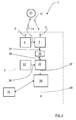
- the radar system 3 comprises a transceiver arrangement 5 that is arranged for generating and transmitting sweep signals in the form of FMCW (Frequency Modulated Continuous Wave) chirp signals 11, and to receive reflected signals 12, where the transmitted chirp signals 11 have been reflected by an object 31.
- FMCW Frequency Modulated Continuous Wave
- the transceiver arrangement 5 comprises a transmitter arrangement 4 with a transmit antenna arrangement 8, a receiver arrangement 7 with a receiver antenna arrangement 9, an Analog to Digital Converter (ADC) arrangement 32 and sampling and timing arrangement 33.
- ADC Analog to Digital Converter
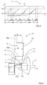
- transmitted signal 11 constituting a so-called chirp signal that is in the form of a continuous sinusoid where the frequency varies from a first frequency f start to a second frequency f stop over the course of a ramp, where the magnitude of the first frequency f start falls below the magnitude of the second frequency f stop .
- the chirp signal 11 comprises repeating cycles of a plurality N of frequency ramps r where a radar cycle for the chirp signal 4 lasts for a certain radar cycle time t c , each ramp lasting a certain ramp time t r and where there is a certain delay time t D between adjacent ramps r.
- Each ramp r has a period time T that equals a sum of the ramp time t r and the delay time t D .
- the delay time t D may be essentially zero.
- the reflected signals 12 are received by the receiver arrangement 7 via the receiver antenna arrangement 9.
- the received signals 12, thus constituted by reflected radar echoes, are then mixed with the transmitted chirp signals 11 in the receiver arrangement 9.
- This may be a single channel mixer, or a two channel mixer comprising both in-phase and quadrature components.
- an IF (Intermediate Frequency) signal 34 is acquired, which may be real or, in the case of quadrature mixer, imaginary.
- the IF signal 34 is filtered in an IF filter 35 such that a filtered IF signal 36 is acquired.
- the frequency of the filtered IF signal 36 relates to the target distance and is transferred to the corresponding ADC arrangement 32, where the filtered IF signal 36 is sampled at a certain predetermined sampling frequency f s and converted to a digital IF signal 37 comprising sample points in a previously known manner, the sampling frequency f s being provided in the form of a sampling and timing signal 38 produced by the sampling and timing arrangement 33 that is connected to the ADC arrangement 32.
- the ADC arrangement 32 is connected to a DSP arrangement 39 that is adapted for radar signal by means of well-known FFT (Fast Fourier Transform) processing of an FMCW radar signal to extract objects within the field of view 10.
- FFT Fast Fourier Transform
- a range FFT function is arranged to convert the filtered digital IF signal 36 to a range domain
- a Doppler FFT function is arranged to combine the results from successive chirp signal ramps, or other suitable Doppler radar cycles, into the Doppler domain.
- This results in an output 40 comprising Range-Doppler matrices that are transferred for further processing, which is not further discussed here, many examples of such further processing being well-known in the art.
- the radar system 3 also comprises a control unit 15.
- the control unit 15 should be regarded as a control unit arrangement that is in the form of one unit or several units that either co-operate or handle different tasks more or less independently. In the case of several units, these may be placed adjacent to each other, or in a distributed manner.
- the control unit is here shown connected to the DSP arrangement 39, of course this is not necessary; the control unit 15 may be connected to several components and/or other control units.
- the transmitter antenna arrangement 6 when in use, sends a signal laterally in the pointing direction P when the vehicle 1 runs past a parking 13, the radar system 3 having said certain field of view 10 that passes along the parking 13.
- the radar system 3 then receives echoes of the transmitted signals 11 by means of the receiver antenna arrangement 8 where the transmitted signals 11 have been reflected by an object 31.
- the field of view 10 corresponds to the beamwidth of the antenna arrangements 6, 9 in a previously known manner.
- the above is repeated as many times as necessary at a predetermined frequency band, while the vehicle moves along the parking 13 in the forward direction F, to obtain required information regarding possible parking spots.
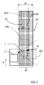
- each measure results in a measuring point 14, where the control unit is arranged to use each measuring point 14 to form a spectrum density map 30, as indicated in Figure 7 , for each radar cycle along the main field of view 10.
- the control unit 15 is thus arranged to combine at least two spectrum density maps to form a combined spectrum density map.
- a radar cycle is one observation phase in which the radar acquires data, processes the date on several signal processing levels and sends out available results. This can be a fixed time interval (i.e. 40 to 60 milliseconds), or it can be a dynamic time interval depending on environment conditions and processing load.
- the spectrum density map 30 comprises range and angle spectrum data.
- the spectrum density map 30 comprises a calculated returned amount of energy from stationary measuring points.
- the data comprised in the spectrum density map 30 may be taken from either the range FFT function or the Doppler FFT function.
- Each measuring point is thus detected several times as the vehicle 1 moves in the forward direction F during a plurality of sample times, where at each sample time measuring points with the field of view 10 are detected.
- the position of a measuring point 14 is determined with respect to the vehicle's position by a target distance T, running between the measuring point 14 and the transmitter antenna arrangement, and a target angle ⁇ running between the forward direction F and an extension 18 of the target distance T. As the vehicle approaches a certain measuring point 14, the target angle ⁇ increases.
- each measurement point results in a complex number that is derived from the range FFT function by means of the control unit 15 and turns with the phase difference ⁇ from ramp to ramp.
- Each complex number comprises a phase and a magnitude, where the direction turns with the phase difference ⁇ between adjacent ramps.
- the control unit 15 is according to some aspects arranged to rotate all measurement vectors for a certain object using the calculated phase difference ⁇ such that they are added in phase. This means that consecutive measurements vectors are rotated an integer k times the phase difference ⁇ , where the integer k runs from 0 to V-1 where V is the number of measurement vectors.
- FIG. 6 This is illustrated in Figure 6 , where there is a first vector v 1 , a second vector v 2 , a third vector v 3 and a fourth vector v 4 .
- the first vector v 1 is used as a reference vector and is rotated 0°, such that the rotated first vector v 1 equals the first vector v 1 .
- the second vector v 2 has a phase difference ⁇ relative the first vector v 1 and is rotated back ⁇ to form a rotated second vector v 2 '
- the third vector v 3 has a phase difference ⁇ relative the second vector v 2 and is rotated back 2 ⁇ to form a rotated third vector v 3 '
- the fourth vector v 4 has a phase difference ⁇ relative the third vector v 3 and is rotated back 3 ⁇ to form a rotated fourth vector v 4 '.
- the first vector v 1 and the rotated vectors v 2 ', v 3 ', v 4 ' all add in phase since the measurement point is stationary. In Figure 6 , only a few vectors are shown for explanatory reasons.
- c 0 is the speed of light in vacuum.
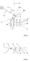
- all receive channels, corresponding to the receiver antenna devices 9a, 9b, 9c, 9d, are combined by means of beamforming.
- the receiver antenna arrangement 9 comprises four receiver antenna devices; a first receiver antenna device 9a, a second receiver antenna device 9b, a third receiver antenna device 9c and a fourth receiver antenna device 9d.
- a reflected signal 12 comprises a wavefront that here is illustrated at two times, constituting a first time wavefront 26a and a second time wavefront 26b, the first time wavefront 26a and the second time wavefront 26b thus illustrating the same wavefront at two different times.
- the reflected signal 12 has an inclination ⁇ relative the boresight direction B, where the inclination ⁇ constitutes a direction of arrival (DOA), ⁇ constituting a DOA angle.
- DOA direction of arrival
- the DOA angle ⁇ results in that the first time wavefront 26a reaches the first receiver antenna device 9a first, then the second receiver antenna device 9b and so on. There is thus a delay time ⁇ t that occurs between when the first time wavefront 26a reaches the first receiver antenna device 9a and when the second time wavefront 26b reaches the second receiver antenna device 9b, and this delay time ⁇ t corresponds to a certain delay distance d and a certain delay phase ⁇ , and depends on the DOA angle ⁇ .
- the delay time ⁇ t is calculated by the control unit 15, and then the corresponding delay phase difference ⁇ is derived.
- Equation (4) follows from trigonometry in Figure 5 .
- the processing is done on all receive channels separately by adding a phase rotation that is introduced due to the Doppler effect, where there is a phase rotation performed for a determined complex signal at a specific antenna. As stationary objects having different angles to the system have different relative velocities, this separates the energy received from objects at different angles.
- a complete spectrum density map 30 is acquired in a Cartesian grid 24 that is combined from all cycles during the passing of the main field of view 10 and having a certain depth R, providing a dense estimation of energy returns 14, 25 (only a few indicated in the Figure) instead of single separate detection points.
- An energy return is any type of received reflection, for example from a measuring point 14. In this way, a two-dimensional detailed top view of the parking 13 is obtained, where all energy returns are accounted for.
- a camera device and image processing algorithms are used for identification and classification of objects.
- three objects 20a, 20b, 20c are shown.
- An advantage of keeping all information is that for example a rear light reflector provides a relatively high degree of reflection, but does in itself not provide all data necessary for determining the extension of a vehicle.
- a radar system that focusses on detections having high degrees of reflection and discards other detections will lose valuable information.
- parking spaces may be detected with a high degree of accuracy, i.e. it may be determined whether there is a useful parking spot 21 available, i.e. a spot which has a sufficient depth 22 and sufficient length 23 admit parking of the vehicle 1.
- the present disclosure also relates to a method for a vehicle Doppler radar system 3 that is used in a vehicle 1 having a forward running direction F.
- the method comprises the steps of:
- the method further comprises:
- the radar system may be implemented in any type of vehicle such as cars, trucks and buses as well as boats and aircraft.
- the constitution of the antenna devices comprised in the transmitter antenna arrangement 6 and the receiver antenna arrangement 9 may be of any suitable design, such as slot antennas of patch antennas.
- the transmitter antenna arrangement 6 and receiver antenna arrangement 9 may be combined in one antenna arrangement that is arranged for both transmission and reception by means of, for example, time division.
- the number of antenna devices comprised in the transmitter antenna arrangement 6 and the receiver antenna arrangement 9 may vary; there should be at least one transmitter antenna device and at least one receiver antenna device 9a, 9b, 9c, 9d.
- the present disclosure relates to a vehicle FMCW (Frequency Modulated Continuous Wave) Doppler radar system 3 comprising a transmitter arrangement 4, a receiver arrangement 7 and at least one control unit 15, the radar system 3 being arranged to be mounted in a vehicle 1, where the transmitter arrangement 4 comprises a transmitter antenna arrangement 6 arranged for transmitting signals 11, and where the receiver arrangement 7 comprises a receiver antenna arrangement 9 arranged for receiving reflected signals 12, the radar system 3 being arranged to obtain a plurality of measure results from the received reflected signals 12 along a main field of view 10 during at least two radar cycles where each radar cycle comprises a plurality of FMCW ramps.
- FMCW Frequency Modulated Continuous Wave
- said control unit 15 is arranged to form a spectrum density map 30 from measuring points 14 along the main field of view 10, where each measure result results in a measuring point 14, where said control unit 15 is arranged to combine at least two spectrum density maps to form a combined spectrum density map.
- each spectrum density map 30 comprises range and angle spectrum.
- said control unit 15 is arranged to calculate each spectrum density map 30 by means of either data from a range FFT (Fast Fourier Transform) function or a Doppler FFT function, where the radar system 3 comprises a DSP (Digital Signal Processor) function 39 that is arranged to perform said FFT functions.
- a range FFT Fast Fourier Transform
- a Doppler FFT function where the radar system 3 comprises a DSP (Digital Signal Processor) function 39 that is arranged to perform said FFT functions.
- said control unit 15 is arranged to determine a phase difference ⁇ between adjacent FMCW ramps r for each measuring point 14, to determine a measurement vector v 1 , v 2 , v 3 , v 4 comprising direction and magnitude for each measuring point 14, and to perform a rotation of each measurement vector v 1 , v 2 , v 3 , v 4 with said phase difference ⁇ such that the rotated measurement vectors v 1 ', v 2 ', v 3 ', v 4 ' that correspond to stationary measuring points 14 add in phase.
- the receiver antenna arrangement 9 comprises at least two receiver antenna devices 9a, 9b, 9c, 9d with corresponding receive channels
- said control unit 15 is arranged to combine the receive channels of said receiver antenna devices 9a, 9b, 9c, 9d by means of beamforming, where each wavefront 12a, 12b corresponding to the received reflected signals 12 reach adjacent receiver antenna devices 9a, 9b, 9c, 9d with a delay time ⁇ t that corresponds to a certain delay distance d and a certain delay phase ⁇ that depends on a direction of arrival DOA angle ⁇
- said control unit 15 is arranged to compensate for said delay phase ⁇ by means of a compensating rotation of a determined complex signal for each antenna device 9a, 9b, 9c, 9d.
- the radar system 3 is arranged to determine whether there is sufficient parking space available.
- the present disclosure also relates to a method for a vehicle FMCW (Frequency Modulated Continuous Wave) Doppler radar system 3 that is used in a vehicle 1, where the method comprises:
- each spectrum density map 30 uses range and angle spectrum.
- each spectrum density map 30 is calculated by either using data from a range FFT (Fast Fourier Transform) function or using a Doppler FFT function.
- range FFT Fast Fourier Transform
- the method further comprises:
- the radar system 3 uses at least two receiver antenna devices 9a, 9b, 9c, 9d with corresponding receive channels, where the method comprises combining the receive channels of said receiver antenna devices 9a, 9b, 9c, 9d using beamforming, where each wavefront 12a, 12b corresponding to the received reflected signals 12 reach adjacent receiver antenna devices 9a, 9b, 9c, 9d with a delay time ⁇ t that corresponds to a certain delay distance d and a certain delay phase ⁇ that depends on a direction of arrival (DOA) angle ⁇ , where the method further comprises compensating for said delay phase ⁇ by performing a compensating rotation of a determined complex signal for each antenna device 9a, 9b, 9c, 9d.
- DOA direction of arrival
- the method comprises determining whether there is sufficient parking space available.
Landscapes
- Engineering & Computer Science (AREA)
- Remote Sensing (AREA)
- Radar, Positioning & Navigation (AREA)
- Physics & Mathematics (AREA)
- Computer Networks & Wireless Communication (AREA)
- General Physics & Mathematics (AREA)
- Electromagnetism (AREA)
- Signal Processing (AREA)
- Radar Systems Or Details Thereof (AREA)
Priority Applications (7)
| Application Number | Priority Date | Filing Date | Title |
|---|---|---|---|
| EP21175247.2A EP3907529A1 (fr) | 2016-07-01 | 2016-07-01 | Radar de véhicule pour détection de l'environnement |
| EP16177581.2A EP3264131A1 (fr) | 2016-07-01 | 2016-07-01 | Radar de véhicule pour détection de l'environnement |
| JP2018567748A JP6751993B2 (ja) | 2016-07-01 | 2017-06-29 | 環境検出用の車両用レーダ |
| KR1020197000017A KR102176025B1 (ko) | 2016-07-01 | 2017-06-29 | 환경 검출을 위한 차량 레이더 |
| PCT/EP2017/066152 WO2018002233A1 (fr) | 2016-07-01 | 2017-06-29 | Radar de véhicule pour détection environnementale |
| US16/313,767 US11105919B2 (en) | 2016-07-01 | 2017-06-29 | Vehicle radar for environmental detection |
| CN201780040947.7A CN109477892B (zh) | 2016-07-01 | 2017-06-29 | 用于环境检测的车辆雷达 |
Applications Claiming Priority (1)
| Application Number | Priority Date | Filing Date | Title |
|---|---|---|---|
| EP16177581.2A EP3264131A1 (fr) | 2016-07-01 | 2016-07-01 | Radar de véhicule pour détection de l'environnement |
Related Child Applications (1)
| Application Number | Title | Priority Date | Filing Date |
|---|---|---|---|
| EP21175247.2A Division EP3907529A1 (fr) | 2016-07-01 | 2016-07-01 | Radar de véhicule pour détection de l'environnement |
Publications (1)
| Publication Number | Publication Date |
|---|---|
| EP3264131A1 true EP3264131A1 (fr) | 2018-01-03 |
Family
ID=56292618
Family Applications (2)
| Application Number | Title | Priority Date | Filing Date |
|---|---|---|---|
| EP21175247.2A Pending EP3907529A1 (fr) | 2016-07-01 | 2016-07-01 | Radar de véhicule pour détection de l'environnement |
| EP16177581.2A Ceased EP3264131A1 (fr) | 2016-07-01 | 2016-07-01 | Radar de véhicule pour détection de l'environnement |
Family Applications Before (1)
| Application Number | Title | Priority Date | Filing Date |
|---|---|---|---|
| EP21175247.2A Pending EP3907529A1 (fr) | 2016-07-01 | 2016-07-01 | Radar de véhicule pour détection de l'environnement |
Country Status (6)
| Country | Link |
|---|---|
| US (1) | US11105919B2 (fr) |
| EP (2) | EP3907529A1 (fr) |
| JP (1) | JP6751993B2 (fr) |
| KR (1) | KR102176025B1 (fr) |
| CN (1) | CN109477892B (fr) |
| WO (1) | WO2018002233A1 (fr) |
Cited By (2)
| Publication number | Priority date | Publication date | Assignee | Title |
|---|---|---|---|---|
| CN111783595A (zh) * | 2020-06-24 | 2020-10-16 | 中国第一汽车股份有限公司 | 一种车辆泊车方法、装置、车载设备及存储介质 |
| RU2761928C1 (ru) * | 2021-03-26 | 2021-12-14 | Общество с ограниченной ответственностью "Научно-производственное предприятие "ИТЭЛМА" (ООО "НПП "ИТЭЛМА") | Радиолокационный датчик для предупреждения столкновений транспортного средства |
Families Citing this family (8)
| Publication number | Priority date | Publication date | Assignee | Title |
|---|---|---|---|---|
| DE102018104243B3 (de) * | 2018-02-26 | 2019-05-16 | Autoliv Development Ab | Verfahren und System zur Erkennung von für ein Fahrzeug geeigneten Parklücken |
| CN112534298A (zh) * | 2018-08-07 | 2021-03-19 | 株式会社村田制作所 | 雷达装置 |
| DE112019005851T5 (de) * | 2018-11-22 | 2021-09-09 | Murata Manufacturing Co., Ltd. | Radarvorrichtung, fahrzeug und objektpositionserfassungsverfahren |
| KR20200100469A (ko) * | 2019-02-18 | 2020-08-26 | 삼성메디슨 주식회사 | 아날로그 빔포머 |
| US11196171B2 (en) * | 2019-07-23 | 2021-12-07 | Veoneer Us, Inc. | Combined waveguide and antenna structures and related sensor assemblies |
| KR20210082946A (ko) | 2019-12-26 | 2021-07-06 | 삼성전자주식회사 | 레이더 신호 처리 장치 및 방법 |
| KR20210101957A (ko) | 2020-02-11 | 2021-08-19 | 삼성전자주식회사 | 레이더 시스템에서의 객체 속도 검출 방법 및 장치 |
| CN112180372A (zh) * | 2020-08-19 | 2021-01-05 | 福瑞泰克智能系统有限公司 | 一种基于双角雷达的目标检测方法、装置和雷达系统 |
Citations (4)
| Publication number | Priority date | Publication date | Assignee | Title |
|---|---|---|---|---|
| WO2015078682A1 (fr) * | 2013-11-26 | 2015-06-04 | Thales | Radar anticollision, notamment pour un aéronef au roulage, et système anticollision |
| EP2881754A1 (fr) | 2013-12-06 | 2015-06-10 | Autoliv Development AB | Radar de véhicule pour détection de l'environnement |
| US20160018511A1 (en) * | 2014-07-17 | 2016-01-21 | Texas Instruments Incorporated | Distributed Radar Signal Processing in a Radar System |
| DE102014218092A1 (de) * | 2014-09-10 | 2016-03-10 | Volkswagen Aktiengesellschaft | Erstellen eines Abbilds der Umgebung eines Kraftfahrzeugs und Bestimmen der relativen Geschwindigkeit zwischen dem Kraftfahrzeug und Objekten in der Umgebung |
Family Cites Families (17)
| Publication number | Priority date | Publication date | Assignee | Title |
|---|---|---|---|---|
| JP2003202373A (ja) * | 2002-01-07 | 2003-07-18 | Omron Corp | 移動物体検知装置および移動物体検知方法 |
| DE10220837A1 (de) * | 2002-05-08 | 2003-11-27 | Daimler Chrysler Ag | Vorrichtung zur Parklückensuche mittels Radar |
| DE102004052521A1 (de) * | 2004-10-29 | 2006-05-04 | Robert Bosch Gmbh | FMCW-Radar mit Standzielunterdrückung |
| JP4561507B2 (ja) * | 2005-07-08 | 2010-10-13 | 株式会社デンソー | 道路形状認識装置 |
| US7400290B2 (en) * | 2005-12-30 | 2008-07-15 | Valeo Raytheon Systems, Inc. | Vehicle radar system having multiple operating modes |
| US8203481B2 (en) * | 2006-10-06 | 2012-06-19 | Adc Automotive Distance Control Systems Gmbh | Radar system for detecting the surroundings with compensation of interfering signals |
| US7639171B2 (en) * | 2007-09-27 | 2009-12-29 | Delphi Technologies, Inc. | Radar system and method of digital beamforming |
| JP5468304B2 (ja) * | 2009-05-20 | 2014-04-09 | 株式会社東芝 | レーダ装置 |
| JP2011220779A (ja) * | 2010-04-07 | 2011-11-04 | Toyota Motor Corp | 障害物検出装置 |
| US9594159B2 (en) * | 2013-07-15 | 2017-03-14 | Texas Instruments Incorporated | 2-D object detection in radar applications |
| DE102014213190A1 (de) * | 2014-06-10 | 2015-12-17 | Robert Bosch Gmbh | Verfahren zur Objektortung mit einem FMCW-Radar |
| JP6406601B2 (ja) * | 2014-08-05 | 2018-10-17 | パナソニックIpマネジメント株式会社 | レーダ装置および物体検知方法 |
| US9784820B2 (en) * | 2014-09-19 | 2017-10-10 | Delphi Technologies, Inc. | Radar system with phase based multi-target detection |
| US9470777B2 (en) * | 2014-09-19 | 2016-10-18 | Delphi Technologies, Inc. | Radar system for automated vehicle with phase change based target catagorization |
| US10061016B2 (en) * | 2014-12-29 | 2018-08-28 | Texas Instruments Incorporated | Phase noise measurement in a cascaded radar system |
| EP3098623A1 (fr) * | 2015-05-25 | 2016-11-30 | Autoliv Development AB | Système de radar de véhicule |
| US10775489B2 (en) * | 2016-12-15 | 2020-09-15 | Texas Instruments Incorporated | Maximum measurable velocity in frequency modulated continuous wave (FMCW) radar |
-
2016
- 2016-07-01 EP EP21175247.2A patent/EP3907529A1/fr active Pending
- 2016-07-01 EP EP16177581.2A patent/EP3264131A1/fr not_active Ceased
-
2017
- 2017-06-29 KR KR1020197000017A patent/KR102176025B1/ko active IP Right Grant
- 2017-06-29 WO PCT/EP2017/066152 patent/WO2018002233A1/fr active Application Filing
- 2017-06-29 JP JP2018567748A patent/JP6751993B2/ja active Active
- 2017-06-29 US US16/313,767 patent/US11105919B2/en active Active
- 2017-06-29 CN CN201780040947.7A patent/CN109477892B/zh active Active
Patent Citations (4)
| Publication number | Priority date | Publication date | Assignee | Title |
|---|---|---|---|---|
| WO2015078682A1 (fr) * | 2013-11-26 | 2015-06-04 | Thales | Radar anticollision, notamment pour un aéronef au roulage, et système anticollision |
| EP2881754A1 (fr) | 2013-12-06 | 2015-06-10 | Autoliv Development AB | Radar de véhicule pour détection de l'environnement |
| US20160018511A1 (en) * | 2014-07-17 | 2016-01-21 | Texas Instruments Incorporated | Distributed Radar Signal Processing in a Radar System |
| DE102014218092A1 (de) * | 2014-09-10 | 2016-03-10 | Volkswagen Aktiengesellschaft | Erstellen eines Abbilds der Umgebung eines Kraftfahrzeugs und Bestimmen der relativen Geschwindigkeit zwischen dem Kraftfahrzeug und Objekten in der Umgebung |
Cited By (2)
| Publication number | Priority date | Publication date | Assignee | Title |
|---|---|---|---|---|
| CN111783595A (zh) * | 2020-06-24 | 2020-10-16 | 中国第一汽车股份有限公司 | 一种车辆泊车方法、装置、车载设备及存储介质 |
| RU2761928C1 (ru) * | 2021-03-26 | 2021-12-14 | Общество с ограниченной ответственностью "Научно-производственное предприятие "ИТЭЛМА" (ООО "НПП "ИТЭЛМА") | Радиолокационный датчик для предупреждения столкновений транспортного средства |
Also Published As
| Publication number | Publication date |
|---|---|
| CN109477892A (zh) | 2019-03-15 |
| CN109477892B (zh) | 2023-06-23 |
| WO2018002233A1 (fr) | 2018-01-04 |
| JP6751993B2 (ja) | 2020-09-09 |
| JP2019525145A (ja) | 2019-09-05 |
| US20190170870A1 (en) | 2019-06-06 |
| EP3907529A1 (fr) | 2021-11-10 |
| KR102176025B1 (ko) | 2020-11-06 |
| US11105919B2 (en) | 2021-08-31 |
| KR20190014061A (ko) | 2019-02-11 |
Similar Documents
| Publication | Publication Date | Title |
|---|---|---|
| US11105919B2 (en) | Vehicle radar for environmental detection | |
| EP3147685B1 (fr) | Système de radar à ouverture synthétique de véhicule | |
| US5818383A (en) | Interferometric moving vehicle imaging apparatus and method | |
| CN107683422B (zh) | 车辆雷达系统 | |
| US20050179579A1 (en) | Radar receiver motion compensation system and method | |
| US11249180B2 (en) | Method and device for ascertaining transverse relative velocity components of radar targets | |
| US11762084B2 (en) | Vehicle radar system | |
| JP3821688B2 (ja) | レーダ装置 | |
| US11280882B2 (en) | Method and radar device for ascertaining radial relative acceleration of at least one target | |
| EP3460512B1 (fr) | Radar de véhicule pour détection de l'environnement | |
| US11841416B2 (en) | Radar system for a vehicle | |
| Baumgartner et al. | Multi-channel SAR for ground moving target indication | |
| US5559516A (en) | Dual cancellation interferometric AMTI radar | |
| US5559515A (en) | Channel switching interferometric AMTI radar | |
| JP3865761B2 (ja) | レーダ装置 | |
| US6982668B1 (en) | Tangential velocity measurement using interferometric MTI radar | |
| US11333754B2 (en) | Detection of parking row orientation | |
| JP7224292B2 (ja) | レーダ装置およびそれを備える自動車 | |
| US11493596B2 (en) | Estimation of cartesian velocities of extended radar objects using a radar sensor | |
| CN114594466A (zh) | 用于确定目标的自有速度估计值和角度估计值的方法 | |
| US12000950B2 (en) | Estimation of transverse velocities or cartesian velocities of point targets with a radar sensor | |
| US20200371199A1 (en) | Estimation of transverse velocities or cartesian velocities of point targets with a radar sensor | |
| JPS61140883A (ja) | 目標追尾高分解能レ−ダ | |
| Lv et al. | Ground moving target indication and parameters estimation using a dual-frequency synthetic aperture radar |
Legal Events
| Date | Code | Title | Description |
|---|---|---|---|
| PUAI | Public reference made under article 153(3) epc to a published international application that has entered the european phase |
Free format text: ORIGINAL CODE: 0009012 |
|
| STAA | Information on the status of an ep patent application or granted ep patent |
Free format text: STATUS: THE APPLICATION HAS BEEN PUBLISHED |
|
| AK | Designated contracting states |
Kind code of ref document: A1 Designated state(s): AL AT BE BG CH CY CZ DE DK EE ES FI FR GB GR HR HU IE IS IT LI LT LU LV MC MK MT NL NO PL PT RO RS SE SI SK SM TR |
|
| AX | Request for extension of the european patent |
Extension state: BA ME |
|
| STAA | Information on the status of an ep patent application or granted ep patent |
Free format text: STATUS: REQUEST FOR EXAMINATION WAS MADE |
|
| RAP1 | Party data changed (applicant data changed or rights of an application transferred) |
Owner name: VEONEER SWEDEN AB |
|
| 17P | Request for examination filed |
Effective date: 20180628 |
|
| RBV | Designated contracting states (corrected) |
Designated state(s): AL AT BE BG CH CY CZ DE DK EE ES FI FR GB GR HR HU IE IS IT LI LT LU LV MC MK MT NL NO PL PT RO RS SE SI SK SM TR |
|
| STAA | Information on the status of an ep patent application or granted ep patent |
Free format text: STATUS: EXAMINATION IS IN PROGRESS |
|
| 17Q | First examination report despatched |
Effective date: 20190625 |
|
| STAA | Information on the status of an ep patent application or granted ep patent |
Free format text: STATUS: EXAMINATION IS IN PROGRESS |
|
| STAA | Information on the status of an ep patent application or granted ep patent |
Free format text: STATUS: THE APPLICATION HAS BEEN REFUSED |
|
| 18R | Application refused |
Effective date: 20210627 |