EP3264072B1 - Überprüfungssystem - Google Patents
Überprüfungssystem Download PDFInfo
- Publication number
- EP3264072B1 EP3264072B1 EP17159082.1A EP17159082A EP3264072B1 EP 3264072 B1 EP3264072 B1 EP 3264072B1 EP 17159082 A EP17159082 A EP 17159082A EP 3264072 B1 EP3264072 B1 EP 3264072B1
- Authority
- EP
- European Patent Office
- Prior art keywords
- support
- inspection
- hole
- barrel
- work piece
- Prior art date
- Legal status (The legal status is an assumption and is not a legal conclusion. Google has not performed a legal analysis and makes no representation as to the accuracy of the status listed.)
- Active
Links
Images


Classifications
-
- G—PHYSICS
- G06—COMPUTING OR CALCULATING; COUNTING
- G06T—IMAGE DATA PROCESSING OR GENERATION, IN GENERAL
- G06T7/00—Image analysis
- G06T7/0002—Inspection of images, e.g. flaw detection
- G06T7/0004—Industrial image inspection
-
- B—PERFORMING OPERATIONS; TRANSPORTING
- B25—HAND TOOLS; PORTABLE POWER-DRIVEN TOOLS; MANIPULATORS
- B25J—MANIPULATORS; CHAMBERS PROVIDED WITH MANIPULATION DEVICES
- B25J9/00—Program-controlled manipulators
- B25J9/0084—Program-controlled manipulators comprising a plurality of manipulators
- B25J9/0087—Dual arms
-
- G—PHYSICS
- G01—MEASURING; TESTING
- G01B—MEASURING LENGTH, THICKNESS OR SIMILAR LINEAR DIMENSIONS; MEASURING ANGLES; MEASURING AREAS; MEASURING IRREGULARITIES OF SURFACES OR CONTOURS
- G01B11/00—Measuring arrangements characterised by the use of optical techniques
- G01B11/08—Measuring arrangements characterised by the use of optical techniques for measuring diameters
- G01B11/10—Measuring arrangements characterised by the use of optical techniques for measuring diameters of objects while moving
- G01B11/105—Measuring arrangements characterised by the use of optical techniques for measuring diameters of objects while moving using photoelectric detection means
-
- G—PHYSICS
- G01—MEASURING; TESTING
- G01B—MEASURING LENGTH, THICKNESS OR SIMILAR LINEAR DIMENSIONS; MEASURING ANGLES; MEASURING AREAS; MEASURING IRREGULARITIES OF SURFACES OR CONTOURS
- G01B11/00—Measuring arrangements characterised by the use of optical techniques
- G01B11/14—Measuring arrangements characterised by the use of optical techniques for measuring distance or clearance between spaced objects or spaced apertures
-
- G—PHYSICS
- G01—MEASURING; TESTING
- G01B—MEASURING LENGTH, THICKNESS OR SIMILAR LINEAR DIMENSIONS; MEASURING ANGLES; MEASURING AREAS; MEASURING IRREGULARITIES OF SURFACES OR CONTOURS
- G01B11/00—Measuring arrangements characterised by the use of optical techniques
- G01B11/24—Measuring arrangements characterised by the use of optical techniques for measuring contours or curvatures
- G01B11/2416—Measuring arrangements characterised by the use of optical techniques for measuring contours or curvatures of gears
-
- G—PHYSICS
- G01—MEASURING; TESTING
- G01B—MEASURING LENGTH, THICKNESS OR SIMILAR LINEAR DIMENSIONS; MEASURING ANGLES; MEASURING AREAS; MEASURING IRREGULARITIES OF SURFACES OR CONTOURS
- G01B11/00—Measuring arrangements characterised by the use of optical techniques
- G01B11/24—Measuring arrangements characterised by the use of optical techniques for measuring contours or curvatures
- G01B11/245—Measuring arrangements characterised by the use of optical techniques for measuring contours or curvatures using a plurality of fixed, simultaneously operating transducers
-
- G—PHYSICS
- G01—MEASURING; TESTING
- G01N—INVESTIGATING OR ANALYSING MATERIALS BY DETERMINING THEIR CHEMICAL OR PHYSICAL PROPERTIES
- G01N21/00—Investigating or analysing materials by the use of optical means, i.e. using sub-millimetre waves, infrared, visible or ultraviolet light
- G01N21/84—Systems specially adapted for particular applications
- G01N21/88—Investigating the presence of flaws or contamination
- G01N21/8806—Specially adapted optical and illumination features
-
- G—PHYSICS
- G01—MEASURING; TESTING
- G01N—INVESTIGATING OR ANALYSING MATERIALS BY DETERMINING THEIR CHEMICAL OR PHYSICAL PROPERTIES
- G01N21/00—Investigating or analysing materials by the use of optical means, i.e. using sub-millimetre waves, infrared, visible or ultraviolet light
- G01N21/84—Systems specially adapted for particular applications
- G01N21/88—Investigating the presence of flaws or contamination
- G01N21/8851—Scan or image signal processing specially adapted therefor, e.g. for scan signal adjustment, for detecting different kinds of defects, for compensating for structures, markings, edges
-
- G—PHYSICS
- G01—MEASURING; TESTING
- G01N—INVESTIGATING OR ANALYSING MATERIALS BY DETERMINING THEIR CHEMICAL OR PHYSICAL PROPERTIES
- G01N21/00—Investigating or analysing materials by the use of optical means, i.e. using sub-millimetre waves, infrared, visible or ultraviolet light
- G01N21/84—Systems specially adapted for particular applications
- G01N21/88—Investigating the presence of flaws or contamination
- G01N21/95—Investigating the presence of flaws or contamination characterised by the material or shape of the object to be examined
- G01N21/9515—Objects of complex shape, e.g. examined with use of a surface follower device
-
- G—PHYSICS
- G01—MEASURING; TESTING
- G01N—INVESTIGATING OR ANALYSING MATERIALS BY DETERMINING THEIR CHEMICAL OR PHYSICAL PROPERTIES
- G01N21/00—Investigating or analysing materials by the use of optical means, i.e. using sub-millimetre waves, infrared, visible or ultraviolet light
- G01N21/84—Systems specially adapted for particular applications
- G01N21/88—Investigating the presence of flaws or contamination
- G01N21/95—Investigating the presence of flaws or contamination characterised by the material or shape of the object to be examined
- G01N21/952—Inspecting the exterior surface of cylindrical bodies or wires
-
- H—ELECTRICITY
- H04—ELECTRIC COMMUNICATION TECHNIQUE
- H04N—PICTORIAL COMMUNICATION, e.g. TELEVISION
- H04N7/00—Television systems
- H04N7/18—Closed-circuit television [CCTV] systems, i.e. systems in which the video signal is not broadcast
- H04N7/181—Closed-circuit television [CCTV] systems, i.e. systems in which the video signal is not broadcast for receiving images from a plurality of remote sources
-
- G—PHYSICS
- G01—MEASURING; TESTING
- G01N—INVESTIGATING OR ANALYSING MATERIALS BY DETERMINING THEIR CHEMICAL OR PHYSICAL PROPERTIES
- G01N21/00—Investigating or analysing materials by the use of optical means, i.e. using sub-millimetre waves, infrared, visible or ultraviolet light
- G01N21/84—Systems specially adapted for particular applications
- G01N21/88—Investigating the presence of flaws or contamination
- G01N21/8851—Scan or image signal processing specially adapted therefor, e.g. for scan signal adjustment, for detecting different kinds of defects, for compensating for structures, markings, edges
- G01N2021/8887—Scan or image signal processing specially adapted therefor, e.g. for scan signal adjustment, for detecting different kinds of defects, for compensating for structures, markings, edges based on image processing techniques
Definitions
- the present invention relates generally to an inspection system including an inspection device to examine the external features of an object and a control device for controlling the inspection device.
- FA Factory Automation
- Patent Document 1 discloses a visual inspection device that employs a robot.
- Patent Document 2 discloses a visual inspection device that employs a robot.
- Japanese Patent Publication No.2009-14696 describes providing the robot with a camera and an illumination unit so that the visual inspection device may acquire the image information needed to perform a visual inspection of the inspection object.
- a robot controller directs the robot to move the camera relative to the inspection object, and operates the illumination unit together with moving the camera.
- US 2015/254828 A1 describes a machine vision system for automatically identifying and inspecting objects is disclosed, including composable vision-based recognition modules and a decision algorithm to perform the final determination on object type and quality.
- WO 2011/072157 A2 describes imaging of falling objects. Multiple images of a falling object can be captured substantially simultaneously using multiple cameras located at multiple angles around the falling object. An epipolar geometry of the captured images can be determined. The images can be rectified to parallelize epipolar lines of the epipolar geometry. Correspondence points between the images can be identified. At least a portion of the falling object can be digitally reconstructed using the identified correspondence points to create a digital reconstruction.
- US 2013/202195 A1 describes a device and a method which will permit the acquisition and subsequent reconstruction of objects with volume throughout the total external surface.
- This invention is characterised in that it has a particular mode of acquisition on the free fall object in such a way that there is no support surface which prevents acquisition of the surface which would be hidden by said support.
- the invention is also characterised by special modes of distribution of the cameras which optimise image capturing and provide useful information in the subsequent reconstruction of the volume through computer means.
- DE 10 2008 019435 A1 describes a method which involves collecting a measuring component by a fixture. The recording is done in an alignment of the component with cameras or other optical image recording devices. The component is subsequently displaced with the fixture relative to the cameras or the optical image recording devices in its position for optical recording of other areas of its surface areas. The recording in another alignment of the component is done with the camera.
- WO 2015/080669 A1 describes a Flexible Vision Inspector which comprises a first type of illuminator for illuminating an object, a second type of illuminator for projecting light onto the object, and a housing.
- the housing encloses the first type of illuminator, the second type of illuminator or both for preventing interference of illumination to the object for machine vision inspection.
- embodiments of the invention aim to provide an inspection system capable of reducing the amount of time taken for inspection.
- an object for inspection is referred to as a work piece.
- a work piece is exemplified as a part of a machine in the embodiment a work piece is not so limited.
- An inspection system is provided with an inspection device for examining the external features of a work piece, and a control device for controlling the inspection device.
- the inspection device is provided with a first barrel that is substantially column-shaped with a first through hole through which a work piece can pass, and a plurality of imaging units provided on the inner peripheral surface which forms the first through hole in the first barrel.
- the control device includes an image processing unit that processes an image captured by and output from each of the imaging units for the purpose of inspection.
- the plurality of imaging units provided on the inner peripheral surface are capable of obtaining images of substantially all the external features of the work piece by merely passing the work piece through the through hole; thus, it is possible to reduce the amount of time required for inspecting the work piece. As a result, it is possible to inspect all the products within a desired time without depending on inspecting a sample of work pieces.
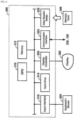
- FIG. 1 is a configuration diagram illustrating an overview of an inspection system according to a first embodiment.
- the inspection system is included on a production line and carries out inspection as a robot 400 (later described) grabs (supports) an individual object to be inspected (work piece W) from work pieces bulk loaded onto a tray or the like.
- the inspection system is a programmable logic controller 100 (PLC 100) with inspection units 200 and 300, and a robot 400 connected thereto ( FIG. 1 ).
- a measurement device 350 is connected to the inspection unit 300, and an imaging device 250 is connected to the inspection unit 200.
- the control device in the inspection system according to this embodiment is collectively composed of the inspection units 200 and 300, and the PLC 100.
- the PLC 100 is provided with a machining device 500 for processing the work piece, a laser marker 510 for applying an identification mark (ID) to the surface of the processed work piece, and a code reader 520 for reading the ID mark applied to the marked work piece.
- the ID mark may include a barcode.
- the inspection system may further include a post production device 600 into which the inspection results output from the PLC 100 enter, and based on said inspection results the post production device 600 determines a grade for the work piece W.
- the IDs of the work pieces W graded by the post production device 600 are read by a code reader 620.
- a work piece W can be categorized based on the grade to control quality.
- the PLC 100 may also determine the parameters for controlling the machining device 500 on the basis of the inspection results, and output the parameters determined to the machining device 500.
- the machining device may thereby be controlled to operate according to the aforementioned parameters to allow the precision of machining the work piece W to change in accordance with the inspection results.
- each of the components in FIG. 1 may communicate with each other via wired or wireless communication.
- FIG. 2 is a schematic view of a configuration of the imaging device 250 and the measurement device 350 depicted in FIG. 1 .
- the imaging device 250 is provided with a substantially column-shaped first barrel 251 that includes a first through hole 260 through which a work piece W can pass.
- the imaging device 250 is further provided with a plurality of imaging units 255 and a plurality of illumination devices 254 which act as light sources; the imaging units 255 and the illumination devices 254 are arranged along the inner peripheral surface 252 which forms the first through hole 260 of the first barrel 251.
- the imaging angle (angle) of an imaging unit 255 is variable.
- this embodiment adjusts each of the imaging units 255 and each of the illumination devices 254 so that the imaging directions and illumination directions are toward the center of the first through hole 260.
- the illumination devices 254 radiate light at an angle that creates no halation at the surface of the object (i.e., the surface of the work piece W).
- the image captured contains no halation and is of uniform intensity.
- the imaging device 250 primarily includes optics composed of lens and the like, and an imaging element such as a charge coupled device (CCD) or a complementary metal oxide semiconductor (CMOS).
- An illumination device 254 mainly includes a light source such as a light emitting diode (LED) or a halogen lamp.
- the measurement device 350 is provided with a substantially column-shaped second barrel 351 that includes a second through hole 360 through which a work piece W can pass.
- the measurement device 350 is further provided with a plurality of measurement sensors 353 along the inner peripheral surface 352 which forms the second through hole 360 of the second barrel 351.
- a measurement sensor 353 uses light from a laser or an LED, or electromagnetic waves such as ultrasonic waves to measure the topology of the work piece W. For instance, the measurement device 350 performs three-dimensional (3-D) measurement.
- this embodiment adjusts the electromagnetic wave measurement axis of each of the measurement sensors 353 to coincide with the direction toward the center of the second through hole 360.
- first barrel 251 and the second barrel 351, and the first through hole 260 and the second through hole 360 are described as substantially (circular) columns, these components may be perfectly circular or elliptical.
- the first through hole 260 and the second through hole 360 are almost the same size and shape.
- the first and second barrels 251, 351 and the first and second through holes 260, 360 are not limited to being substantially circular and maybe polygons.
- a robot 400 is depicted in relation to the imaging device 250 and the measurement device 350 ( FIG. 2 ).
- the robot 400 includes a hand mechanism for grabbing a work piece W, and a joint mechanism for positioning the hand mechanism in a data desired location and direction. Movement of the robot 400 is controlled by a robot controller 401.
- the robot 400 is provided with a first support 410 and a second support 420 which are essentially manipulator arms, and a drive unit 430 moving van mechanism and the joint mechanism via the manipulator arms.
- the drive unit 430 is essentially a servo motor.
- the drive unit contains a motor connected to the rotation shafts of the hand and joint mechanisms, an encoder, and a driver.
- the drive unit 430 detects the rotational angle and rotation speed of the motor shaft with the encoder and feeds the detection result back to the motor driver.
- the motor driver takes the feedback of the detection value and a control value entering from the robot controller 401 and generates a control signal such that the difference in the values is zero; the motor driver then outputs that control signal to the motor.
- the motor rotates according to the control signal, whereby for example, the hand mechanism and the joint mechanism rotate, and the joint of the arm of the first support 410 and the second support 420 move together with the rotation of the motor.
- the object to be examine i.e., the work piece W may be placed on a tray (not shown).
- the robot controller 401 identifies the location and positioning of a work piece W on the basis of information representing the center position (central axis CA, Figure2 ) of the work piece W; this information is obtained from an image of the work piece W on the tray and calculated computed by the PLC 100.
- the robot controller also generates a command for output to the drive unit 430 that positions the hand mechanism of the first support 410 on the robot 400 so that the hand mechanism is positioned at a location in a direction capable of grasping the work piece W; this command is generated on the basis of the aforementioned identified location and positioning of the work pieces W.
- the first support 410 initiates an operation, via the drive unit 430, to grab the work piece W in response to the command.
- the work piece W is held in a predetermined position such that a direction extending along the central axis CA thereof coincides with the direction extending along a virtual axis AR.
- the plurality of barrels i.e., the first barrel 251, and the second barrel 351 are layered along the axis AR.
- the route along which the work piece W passes i.e., moves through the first through hole 260 and the second to whole 360 coincides with the axis AR.
- the axis AR passes through the center (center of gravity) of a substantially circular shape defined by the inner peripheral surface 252 of the first through hole 260 and the center (center of gravity) of the substantially circular shape defined by the inner peripheral surface 352 of the second through hole 360.
- the PLC 100 transmits a control signal to the robot controller 401 for controlling the drive unit 430.
- the control signal represents a signal that controls the drive unit 430 so that the first support 410 moves along the axis AR extending along busy access in FIG. 2 , and passes through the second through hole 660 and the first through hole 260 while the robot holds the work piece W at the predetermined position.
- the PLC 100 also transmits a control signal to the robot controller 401 for controlling the drive unit 430 so that the second support 420 receives the work piece W that has passed through the first through hole 260 from the first support 410 with the work piece W in the aforementioned predetermined position.
- the above-mentioned predetermined position is equivalent to the state that the first support 410 grabs a part (one end) of the work piece W as shown in the figure. Accordingly, the plurality of measurement sensors 353 positioned roughly about the entire periphery of the work piece W measure the topography of the work piece W when the same moves through the second through hole 360; further, the plurality of imaging units 255 positioned about the entire periphery of the workpiece W capture the work piece W as the same moves through the first through hole 260 and is illuminated from directions about the entire periphery thereof.
- the predetermined position determined on the basis of the central axis CA of the work piece W allows the imaging device 250 to capture an image of the work piece W from all directions, and allows the measurement device 350 to measure the surface topography from all directions about the work piece W. This positioning may be determined in advance by experimentation. Note that the predetermined position of the work piece W is preferably determined from the shape and size thereof, and is not limited to the positioning illustrated in FIG. 2 .
- FIG. 3 illustrates one example of a work piece W in the first embodiment.
- the measurement device 350 measures the inner diameter (4), and the outer diameter (5), the step (3) and the gap (2) on the work piece W.
- the imaging device 250 captures an image of a site (1) inspected to determine whether or not there are scratches or damage on the surface of the work piece W.
- the site gripped by the first support 410 so that the work piece W is in the above-mentioned predetermined position is preferably a site that is not to be measured or captured, i.e. none of the sites (1) to (5).
- the PLC 100 The PLC 100
- the PLC 100 is, for example, a computer having a general-purpose architecture; executing programs (command codes) previously installed there on allows the PLC 100 to provide the functions of the embodiment. These kinds of programs may be run while stored on various kinds of recording media, or may be installed on the PLC 100 via a network.
- an operating system may be installed on the general-purpose computer to provide the computer with basic functions, in addition to installing an application to provide functions according to the embodiment.
- the program provided according to the embodiment may call on necessary modules from among the program modules provided as a part of the OS in a predetermined sequence at predetermined times in order to carry out relevant processes.
- the program itself according to the embodiment does not contain the above-mentioned modules, the program can carry out processing in collaboration with the OS.
- the program according to the embodiment may exclude those modules that are provided as a part of the OS.
- the program according to the embodiment may be combined with and provided as one part of another program.
- the program itself does not include the modules contained in the other program with which it is combined, the program may collaborate with other programs to carry out processing.
- the program according to the embodiment may be combined with and provided as one part of another program.
- the functions provided by executing the program may be implemented in whole or in part as a dedicated hardware circuit.
- FIG. 4 illustrates a general configuration of a PLC 100 in the first embodiment.
- the PLC 100 includes a central processing unit (CPU) 110 which is an arithmetic processing unit; a main memory 112 and a hard drive 114 as storage units; an input interface 118; a display controller 120; a communication interface 124; and a data reader-writer 126.
- CPU central processing unit
- main memory 112 and a hard drive 114 as storage units
- an input interface 118
- a display controller 120
- a communication interface 124 a communication interface 124
- a data reader-writer 126 Each of these components is capable of data communication with each other via a bus 128.
- the CPU 110 reads the program (code) installed on the hard drive 114 into main memory 112 and executes the code in a predetermined sequence to thereby carry out various computations.
- the main memory 112 may be a volatile storage device such as a dynamic random access memory (DRAM) which, in addition to the programs read in from the hard drive 114, stores the input image acquired by the imaging device 250, calibration data for the robot 400, information related to the measurement results, and the like.
- the hard drive 114 may store each kind of setting value.
- a semiconductor storage device such as flash memory may be used in addition to or as a substitute for the hard drive 114.
- the input interface 118 mediates data transmission between the CPU 110 and an input device 104 such as a mouse, a keyboard, a touchscreen panel, and the like. In other words, the input interface 118 receives operation instructions provided by a user operating the input device.
- the display controller 120 is connected to a display 102 which is one example of a display device, and controls the display to notify the user of the processing result from the CPU 110. That is, The display controller 120 is connected to a display 102, and controls what is shown on the display 102.
- the network interface 124 mediates data transmission between the CPU 110 and other devices in the inspection system such as the inspection units 200, 300, the robot 400 (and more specifically the robot controller 401), the machining device 500, and the post production device 600.
- the communication interface 124 may be configured by, for example, Ethernet (Registered Trademark), or a universal serial bus (USB).
- the data reader-writer 126 mediates the data transmission between the CPU 110 and the memory card 106 which is a recording medium.
- the program to be executed on the PLC 100 may be distributed while stored on the memory card 106, and the data reader-writer 126 may read the program out from the memory card 106.
- the memory card 106 may be a general-purpose semiconductor storage device such as a Compact Flash (CF) card, and a Secure Digital (SD) card; a magnetic storage medium such as a flexible disk; or an optical storage medium such as compact disk read-only memory (CD-ROM).
- the Inspection Unit 200 The Inspection Unit 200
- FIG. 5 illustrates a general configuration of the inspection unit 200 according to the first embodiment for processing the image.
- the inspection unit 200 includes a central processing unit (CPU) 210; a main memory 212; a hard drive 214; an input interface 218; a display controller 220; a communication interface 224; a camera interface 216; and a data reader-writer 226.
- CPU central processing unit
- the CPU 210 reads the program (code) installed on the hard drive 214 into main memory 212 and executes the code in a predetermined sequence to thereby carry out various computations including processing an image.
- the main memory 212 may be a volatile storage device such as a dynamic random access memory (DRAM) which, in addition to the programs read in from the hard drive 214, stores the input image acquired by the imaging device 250, and the like.
- DRAM dynamic random access memory
- the input interface 218 mediates data transmission between the CPU 210 and an input device 204 such as a mouse, a keyboard, a touchscreen panel, and the like.
- the display controller 220 is connected to a display 202, which is one example of a display device, and controls the display to notify the user of the processing result from the CPU 210.
- the communication interface 224 provides for communication between the CPU 210, and the PLC 100 and imaging device 250.
- the data reader-writer 226 mediates the data transmission between the CPU 210 and the memory card 206 which is a recording medium.
- the memory card 206 is identical to the memory card 106 depicted in FIG. 4 .
- the camera interface 216 mediates the data transmission between the CPU 210 and the imaging device 250. That is, the camera interface 216 is connected to the imaging device 250 which captures an image of the work piece W and generates an input image. More specifically, the camera interface 216 contains an image buffer 216a for temporarily storing an input image from the imaging device 250. Once the input images for a predetermined number of frames are accumulated in the image buffer 216a, the camera interface 216 transfers the input images to the main memory 212. The camera interface 216 also provides the imaging device 250 (and more specifically the imaging units 255) with a capture command in accordance with an internal command generated by the CPU 110.
- the CPU 210 includes the functions of an image processing unit.
- the image processing unit carries out processing on an image through the execution of a program.
- the image data in the image buffer 216a includes the identifier of the imaging unit 255 that captured the image.
- the image processing unit compares patterns between an image captured by each of the imaging units 255 and a corresponding model image and detects pits or scratches on the surface on the basis of the results of the comparison. The results of the image processing is presented on the display 202.
- the Inspection Unit 300 The Inspection Unit 300
- FIG. 6 illustrates a general configuration of an inspection unit 300 according to the first embodiment for processing the measurement data.
- the inspection unit 300 includes a central processing unit (CPU) 310; a main memory 312; a hard drive 314; an input interface 318; a display controller 320; a communication interface 324; and a data reader-writer 326.
- CPU central processing unit
- main memory 312 main memory
- hard drive 314 main memory
- input interface 318 a display controller
- a communication interface 324 a communication interface 324
- a data reader-writer 326 Each of these components is capable of data communication with each other via a bus.
- the CPU 310 reads the program (code) installed on the hard drive 314 into main memory 312 and executes the code in a predetermined sequence to thereby carry out various computations including processing an image.
- the main memory 312 may be a volatile storage device such as a dynamic random access memory (DRAM) which, in addition to the programs read in from the hard drive 314, stores the measurement data acquired by the measurement device 350, and the like.
- DRAM dynamic random access memory
- the input interface 318 mediates data transmission between the CPU 310 and an input device 304 such as a mouse, a keyboard, a touchscreen panel, and the like.
- the display controller 320 is connected to a display 302 which is one example of a display device, and controls the display to notify the user of the processing result from the CPU 310.
- the communication interface 324 provides for communication between the CPU 310, and the PLC 100 and measurement device 350.
- the data reader-writer 326 mediates the data transmission between the CPU 310 and the memory card 306 which is a recording medium.
- the memory card 306 is identical to the memory card 106 depicted in FIG. 4 .
- the camera interface 324 mediates the data transmission between the CPU 310 and the measurement device 350. That is, the communication interface 324 is connected to the measurement device 350 which measures the work piece W and generates measurement data. More specifically, the CPU 310 receives measurement data for the above mentioned sites: the inner diameter (4) and the outer diameter (5), the step (3) and the gap (2) from the measurement device 350 via the communication interface 324. The CPU also provides measurement commands to the measurement device 350 (and more specifically the measurement sensors 353) via the communication interface 324.
- the CPU 310 includes the functions of a measurement processing unit.
- the measurement processing unit carries out processing on measurements through the execution of a program.
- the hard drive 314 stored reference data indicating the outward size of a passing work piece W for use in the measurement processing.
- the measurement processing unit compares the measurement data received for the inner diameter (4) and the outer diameter (5), the step (3) and the gap (2) and compares the same with the reference data; based on the results of the comparison, the measurement processing unit determines the machining precision such as dimensions and size needed by the machining device 500.
- the results of the measurement processing is presented on the display 302.
- the inspection unit 200 sends the PLC 100 the results of image processing.
- the inspection unit 300 sends the PLC 100 the results of measurement processing.
- the PLC 100 determines the parameters needed for the machining device 500 on the basis of the results of image processing and measurement processing; the PLC 100 outputs the parameters determined in the previous stage to the machining device 500.
- the parameters include parameters that control the operation of the machining device 500.
- the machining device 500 may perform machining in accordance with parameters, whereby it is possible to improve on the work piece W by reducing surface scratches or improving the accuracy of the dimensions and size.
- the PLC 100 may also evaluate machining precision such as surface machining dimensions and size on the basis of results from imaging processing and measurement processing; the PLC 100 may also send the results of the evaluation to a post production device 600 via the communication interface 224.
- the post production device 600 determines a grade (categorizes by class) the work pieces W on the basis of the results received from the PLC 100.
- the grade of a work piece W may be managed in association with an ID read from the work piece W by the code reader 620.
- FIG. 7 is a flowchart of an automatic inspection process according to the first embodiment.
- a program following this flowchart may be stored in advance on a storage unit in the PLC 100, and executed by the CPU 110.
- the PLC 100 sends a control signal to the robot 400.
- the first support 410 of the robot 400 grabs the work piece W so that the work piece W is in a predetermined position (step S2).
- the first support 410 moves along the direction of the axis AR ( FIG. 2 ) to thereby move the work piece W linearly along the direction of the axis AR while the work piece W is in the predetermined position.
- the work piece W passes through the second through hole 360 of the measurement device 350 and then passes through the first through hole 260 of the imaging device 250 when moving along the direction of the axis AR.
- the inspection process is carried out when the work piece W passes through the through holes (step S5).
- step S3 The above-described measurement process (step S3), and the imaging process (step S4) are carried out when the work piece W passes through the second through hole 360 and passes through the first through hole 260 respectively during the inspection process (step S5).
- the PLC 100 provides feedback to the above-mentioned previous stage and feedforward to the above-mentioned subsequent stage on the basis of the results of the imaging process and the measurement process (step S7).
- step S9 It is then determined whether or not all the work pieces have been inspected. For instance, the CPU 110 in the PLC 100 may determine whether or not to terminate the inspection process on the basis of a user command entered from the input device 104. If it is determined that processing is not to be terminated (No, at step S9), the processing returns to step S2 and executes the inspection process after step S2 in the same manner. If it is determined that processing is to be terminated (Yes, at step S9) the series of processes ends.
- FIG. 8 illustrates an example of modifying the first barrel according to the first embodiment.
- the illumination device 254 is provided to the first barrel 251 together with the imaging units 255; however, the illumination device 254 is not limited to being disposed on the first barrel 251.
- the inspection system may be provided with an imaging device 250 that is separated into a first device 250A onto which the imaging units 255 may be installed, and a second device 250B onto which the illumination device 254 may be installed ( FIG. 8 ).
- the second device 250B includes a substantially column-shaped third barrel 251 stacked on top of the first barrel 251A of the first device 250A.
- the third barrel 251B includes a third through hole through which a work piece W may pass.
- one or a plurality of illumination devices 254 is disposed on the inner peripheral surface 252B of the third through hole in the third barrel 251B, and the imaging units 255 are disposed on the inner peripheral surface 252A of the first barrel 251A.
- the illumination devices 254 in the third barrel 251B may be installed on an angle that illuminates the inside of the first through hole 260 in the first barrel 251A; hereby, allowing illumination light to enter inside the first through hole makes it possible to satisfy certain illumination conditions when capturing an image. Note that although the third barrel 251B is stacked above the first barrel 251A in FIG. 8 , the third barrel 251B may be arranged below the first barrel 251A.
- FIG. 9 is a schematic view of another inspection device to illustrate the advantages of the inspection system according to the first embodiment.
- a camera is installed on the robot arm ( FIG. 9 ).
- the robot arm rotates so that the camera moves about the work piece W, allowing the device to capture the entire work piece, which is stationary.
- This requires that the timing used by the camera to capture image and the movement of the robot arm are integrated and mutually synchronized; however, this timing may not be within a required turnaround time.
- the inspection device can capture an image of and measure the work piece W from all directions all at once by having the first support 410 of the robot 400 move the work piece W via a through hole along an axis AR. Accordingly, there is no need to synchronize when an image is captured with the rotation of the robot arm. Therefore, this reduces the amount of time required for inspection, and allows the inspection to coincide with the required turnaround time.
- the second example provides explanation of modifications to the first embodiment.
- the second example is useful for understanding the invention defined in the appended claims.
- the measurement device 350 is provided in the above embodiment to take measurements; however, the measurement device 350 may be excluded when it is possible to obtain measurement data from the image captured.
- the imaging unit 255 may be a 3-D camera for taking three-dimensional measurements of the work piece W from the image captured.
- the 3-D image output from the 3-D camera may be used as the basis for detecting contours or topography of the surface of the work piece W. Any cracks or scratches in the work piece W may be examined by comparing the 3D image data obtained to 3D CAD data, or by creating a two-dimensional image from the 3D image.
- the imaging device 250 and the measurement device 350 are provided in different barrels in the inspection system; however, in a further example useful for understanding the invention defined in the appended claims, these devices may be provided in the same barrel.
- the illumination device provided to the imaging device 250 may be an illumination ring (capable of providing illumination from 360°) provided on the inner peripheral surface of the first through hole 260 along the shape of the opening.
- an illumination ring capable of providing illumination from 360°
- certain problems can be more reliably avoided since shadows tend not to form on the surface of the work piece. More specifically, problems where halation occurs due to the specular reflection of illumination light entering the imaging units 255, or where the work piece W has a mirrored surface whereby the light source itself form an image on the surface of the work piece W.
- the illumination devices 254 may be eliminated. More specifically, the illumination devices 254 may be excluded when ambient lighting such as the illumination light from a ceiling fixture in a room sufficiently satisfies the imaging criteria, if the imaging device 250 is arranged above and the measurement device 350 is arranged below along the extending direction of the Z axis in FIG. 2 .
- the imaging device 250 and the measurement device 350 may be mounted for attachment to and detachment from stanchions 700 without being permanently fixed thereto.
- the imaging device 250 and the measurement device 350 may be removed by shifting the same vertically along the stanchions 700 (i.e., the direction the Z axis extends) or along the length thereof (i.e., the direction the Y axis extends). This facilitates swapping in and out various types of imaging devices 250 or measurement devices 350 in accordance with the type of inspection to be performed or the size of the work piece W.
- the PLC 100, the inspection unit 200, and the inspection unit 300 are provided individually in the first embodiment; however, these components may be provided as a single unit. In that case, the functions of the inspection units 200 and 300 may be assembled into the PLC 100.
Landscapes
- Physics & Mathematics (AREA)
- General Physics & Mathematics (AREA)
- Engineering & Computer Science (AREA)
- Analytical Chemistry (AREA)
- Chemical & Material Sciences (AREA)
- Life Sciences & Earth Sciences (AREA)
- Biochemistry (AREA)
- General Health & Medical Sciences (AREA)
- Immunology (AREA)
- Pathology (AREA)
- Health & Medical Sciences (AREA)
- Signal Processing (AREA)
- Computer Vision & Pattern Recognition (AREA)
- Quality & Reliability (AREA)
- Theoretical Computer Science (AREA)
- Multimedia (AREA)
- Robotics (AREA)
- Mechanical Engineering (AREA)
- Investigating Materials By The Use Of Optical Means Adapted For Particular Applications (AREA)
- Length Measuring Devices With Unspecified Measuring Means (AREA)
- Length Measuring Devices By Optical Means (AREA)
Claims (3)
- Überprüfungssystem, umfassend: eine Überprüfungsvorrichtung (250, 350), die zum Untersuchen der äußeren Merkmale eines Objekts konfiguriert ist; und eine Steuervorrichtung (100, 200, 300) zum Steuern der Überprüfungsvorrichtung;
wobei die Überprüfungsvorrichtung Folgendes enthält:einen im Wesentlichen säulenförmigen ersten Zylinder (251), der ein erstes Durchgangsloch (260) enthält, das dazu konfiguriert ist, dass ein Objekt (W) hindurchgeht; undeine Vielzahl von Bildgebungseinheiten (255), die an der inneren Umfangsoberfläche (252) bereitgestellt sind, die das erste Durchgangsloch in dem ersten Zylinder bildet; undeinen im Wesentlichen säulenförmigen zweiten Zylinder (351), der ein zweites Durchgangsloch (360) enthält, das dazu konfiguriert ist, dass das Objekt (W) hindurchgeht; undeine Vielzahl von Messsensoren (353), die an der inneren Umfangsoberfläche (352) bereitgestellt sind, die das zweite Durchgangsloch in dem zweiten Zylinder bildet, und dazu konfiguriert sind, die äußeren Merkmale des Objekts zu messen;wobei die Steuervorrichtung Folgendes enthält:eine Bildverarbeitungseinheit (210), die dazu konfiguriert ist, ein Bild, das durch jede der Bildgebungseinheiten erfasst und ausgegeben wird, zum Zweck der Überprüfung zu verarbeiten; undeine Kommunikationseinheit (124, 224), die zur Kommunikation mit einer externen Vorrichtung (400) konfiguriert ist; undeine Messverarbeitungseinheit (310), die dazu konfiguriert ist, die von den Messsensoren ausgegebenen Messwerte zum Zwecke der Überprüfung zu verarbeiten,wobei die externe Vorrichtung Folgendes enthält:eine Trägervorrichtung, die eine Antriebseinheit (430) und einen ersten Träger (410) mit einem Handmechanismus enthält, wobei der erste Träger dazu konfiguriert ist, das Objekt zu tragen, wobei der erste Träger ein erster Manipulatorarm ist, undwobei die Steuervorrichtung ferner Folgendes enthält:Mittel zum Steuern der Kommunikationseinheit, um ein Steuersignal an die Trägervorrichtung zu übertragen, wobei das Steuersignal dazu konfiguriert ist, die Antriebseinheit so zu steuern, dass der Handmechanismus basierend auf einer Mittelposition des Objekts so positioniert wird, dass der Handmechanismus so positioniert ist, dass er so platziert und ausgerichtet ist, dass er in der Lage ist, das Objekt an einer vorbestimmten Position zu greifen, undwobei die Steuervorrichtung die Kommunikationseinheit veranlasst, ein Steuersignal an die Trägervorrichtung zu übertragen, wobei das Steuersignal dazu konfiguriert ist, die Antriebseinheit so zu steuern, dass sie veranlasst, dass der erste Träger entlang eines Wegs verfährt, der einer virtuellen Achse (AR) entspricht, die durch das erste Durchgangsloch und das zweite Durchgangsloch hindurchgeht, während das Objekt an der vorbestimmten Position getragen wird,wobei der erste Zylinder und der zweite Zylinder entlang der virtuellen Achse (AR) gestapelt sind und die virtuelle Achse eine Achse angibt, die durch einen Schwerpunkt einer Form, die durch die innere Umfangsoberfläche des ersten Durchgangslochs definiert ist, und einen Schwerpunkt einer Form, die durch die innere Umfangsoberfläche des zweiten Durchgangslochs definiert ist, verläuft;wobei die vorbestimmte Position derart eine Position angibt, dass eine Richtung, die sich entlang der Mittelachse (CA) des Objekts erstreckt, mit der Richtung zusammenfällt, die sich entlang der virtuellen Achse (AR) erstreckt. - Überprüfungssystem nach Anspruch 1, wobei die Trägervorrichtung ferner einen zweiten Träger (420) enthält, der dazu konfiguriert ist, das Objekt (W) zu tragen, wobei der zweite Träger ein zweiter Manipulatorarm ist; und
wobei die Steuervorrichtung (100, 200) die Kommunikationseinheit (124, 224) veranlasst, ein Steuersignal an die Trägervorrichtung zu übertragen, wobei das Steuersignal dazu konfiguriert ist, die Antriebseinheit (430) so zu steuern, dass sie veranlasst, dass der zweite Träger das Objekt (W) von dem ersten Träger (410) empfängt, nachdem der erste Träger durch das erste Durchgangsloch (260) hindurchgegangen ist. - Überprüfungssystem nach Anspruch 1 oder 2, wobei die Überprüfungsvorrichtung (250, 350) ferner eine Lichtquelle (254) enthält, die dazu konfiguriert ist, innerhalb des ersten Durchgangslochs (260) zu leuchten.
Applications Claiming Priority (1)
| Application Number | Priority Date | Filing Date | Title |
|---|---|---|---|
| JP2016130458A JP6878781B2 (ja) | 2016-06-30 | 2016-06-30 | 検査システム |
Publications (2)
| Publication Number | Publication Date |
|---|---|
| EP3264072A1 EP3264072A1 (de) | 2018-01-03 |
| EP3264072B1 true EP3264072B1 (de) | 2025-05-14 |
Family
ID=58231462
Family Applications (1)
| Application Number | Title | Priority Date | Filing Date |
|---|---|---|---|
| EP17159082.1A Active EP3264072B1 (de) | 2016-06-30 | 2017-03-03 | Überprüfungssystem |
Country Status (4)
| Country | Link |
|---|---|
| US (1) | US10417754B2 (de) |
| EP (1) | EP3264072B1 (de) |
| JP (1) | JP6878781B2 (de) |
| CN (1) | CN107561082B (de) |
Families Citing this family (20)
| Publication number | Priority date | Publication date | Assignee | Title |
|---|---|---|---|---|
| DE102017207071A1 (de) * | 2017-04-27 | 2018-10-31 | Robert Bosch Gmbh | Prüfvorrichtung zur optischen Prüfung eines Objekts und Objektprüfungsanordnung |
| ES2844349T3 (es) * | 2017-06-21 | 2021-07-21 | Inst Tecnologico De Informatica | Dispositivo para la adquisición y reconstrucción de objetos por inspección visual |
| CN108407909A (zh) * | 2018-02-11 | 2018-08-17 | 常州轻工职业技术学院 | 管道外探伤行走机器人 |
| CN108465648A (zh) * | 2018-04-23 | 2018-08-31 | 苏州香农智能科技有限公司 | 一种基于机器视觉的磁芯自动分拣系统 |
| JP7077807B2 (ja) * | 2018-06-12 | 2022-05-31 | オムロン株式会社 | 画像検査システム及びその制御方法 |
| DE102018114222A1 (de) * | 2018-06-14 | 2019-12-19 | INTRAVIS Gesellschaft für Lieferungen und Leistungen von bildgebenden und bildverarbeitenden Anlagen und Verfahren mbH | Verfahren zum Untersuchen von übereinstimmenden Prüfobjekten |
| CN108872265A (zh) * | 2018-07-23 | 2018-11-23 | 珠海格力智能装备有限公司 | 检测方法、装置及系统 |
| ES2831149T3 (es) * | 2018-10-15 | 2021-06-07 | Fraunhofer Ges Forschung | Sistema y procedimiento para comprobar la forma de un objeto de prueba |
| JP6878391B2 (ja) * | 2018-12-18 | 2021-05-26 | ファナック株式会社 | ロボットシステムとその調整方法 |
| CN109959406B (zh) * | 2019-04-17 | 2024-02-02 | 福州大学 | 轮式旋转悬臂水下桥墩检测装置及其工作方法 |
| US11543364B2 (en) | 2019-05-16 | 2023-01-03 | General Inspection, Llc | Computer-implemented method of automatically generating inspection templates of a plurality of known good fasteners |
| US11162906B2 (en) | 2019-05-16 | 2021-11-02 | General Inspection, Llc | High-speed method and system for inspecting and sorting a stream of unidentified mixed parts |
| US11045842B2 (en) * | 2019-05-16 | 2021-06-29 | General Inspection, Llc | Method and system for inspecting unidentified mixed parts at an inspection station having a measurement axis to identify the parts |
| WO2021062536A1 (en) * | 2019-09-30 | 2021-04-08 | Musashi Auto Parts Canada Inc. | System and method for ai visual inspection |
| JP7192760B2 (ja) * | 2019-12-24 | 2022-12-20 | トヨタ自動車株式会社 | 異物検査方法および異物検査装置 |
| CN111007084B (zh) * | 2020-01-03 | 2023-10-24 | 佛亚智能装备(苏州)有限公司 | 一种轴类表面360度瑕疵检测方法及拍摄机构 |
| CN118578378A (zh) * | 2020-02-19 | 2024-09-03 | 总督科技股份有限公司 | 晶圆转载机构的机械臂校准装置 |
| US11593931B2 (en) | 2020-06-09 | 2023-02-28 | Howmedica Osteonics Corp. | Surgical kit inspection systems and methods for inspecting surgical kits having parts of different types |
| DE102021102122B4 (de) * | 2021-01-29 | 2023-12-28 | Klingelnberg GmbH. | Verfahren und Vorrichtung zum Messen einer Verzahnung |
| KR102823145B1 (ko) * | 2023-02-17 | 2025-06-20 | 경북대학교 산학협력단 | 광섬유 융착 코어 3차원 검사 시스템 |
Citations (2)
| Publication number | Priority date | Publication date | Assignee | Title |
|---|---|---|---|---|
| DE102008019435A1 (de) * | 2008-04-17 | 2009-10-29 | Aicon Metrology Gmbh | Verfahren zum berührungslosen Vermessen dreidimensionaler, komplex geformter Bauteile |
| WO2015080669A1 (en) * | 2013-11-29 | 2015-06-04 | K-One Industries Pte Ltd | Flexible vision inspector |
Family Cites Families (13)
| Publication number | Priority date | Publication date | Assignee | Title |
|---|---|---|---|---|
| US5077477A (en) * | 1990-12-12 | 1991-12-31 | Richard Stroman | Method and apparatus for detecting pits in fruit |
| JPH09152322A (ja) * | 1995-11-30 | 1997-06-10 | Nippon Steel Corp | 表面品質検査方法及び表面品質検査装置 |
| JP2000180678A (ja) * | 1998-12-11 | 2000-06-30 | Sumitomo Electric Ind Ltd | 光ケーブル用溝付スペーサの溝形態異常検出方法および検出装置 |
| JP4069535B2 (ja) * | 1999-02-17 | 2008-04-02 | 東洋製罐株式会社 | 潰れ蓋検出装置 |
| JP2001050905A (ja) * | 1999-08-16 | 2001-02-23 | Ricoh Co Ltd | 円筒体欠陥検査装置 |
| WO2005022076A2 (en) | 2003-08-23 | 2005-03-10 | General Inspection, Llc | Part inspection apparatus |
| US9424634B2 (en) * | 2004-03-04 | 2016-08-23 | Cybernet Systems Corporation | Machine vision system for identifying and sorting projectiles and other objects |
| JP2006153545A (ja) * | 2004-11-26 | 2006-06-15 | Sanyo Special Steel Co Ltd | レーザ走査式鋼材同一断面外径測定装置 |
| JP5218723B2 (ja) * | 2007-06-14 | 2013-06-26 | 株式会社Ihi | 蛍光探傷方法および蛍光探傷装置 |
| JP2009014696A (ja) | 2007-07-09 | 2009-01-22 | Quality Line:Kk | 照度可変照明部及び撮像部の独立可動における外観検査装置 |
| EP2053350A1 (de) * | 2007-10-23 | 2009-04-29 | Zumbach Electronic Ag | Vorrichtung zum optischen Vermessen und/oder Prüfen von länglichen Produkten |
| US8891895B2 (en) * | 2009-12-09 | 2014-11-18 | University Of Utah Research Foundation | Systems and methods for imaging of falling objects |
| EP2511653B1 (de) * | 2009-12-10 | 2014-02-12 | Instituto Tecnológico De Informática | Vorrichtung und verfahren zur erfassung und rekonstruktion von objekten |
-
2016
- 2016-06-30 JP JP2016130458A patent/JP6878781B2/ja active Active
-
2017
- 2017-02-09 CN CN201710071050.2A patent/CN107561082B/zh active Active
- 2017-03-02 US US15/448,487 patent/US10417754B2/en active Active
- 2017-03-03 EP EP17159082.1A patent/EP3264072B1/de active Active
Patent Citations (2)
| Publication number | Priority date | Publication date | Assignee | Title |
|---|---|---|---|---|
| DE102008019435A1 (de) * | 2008-04-17 | 2009-10-29 | Aicon Metrology Gmbh | Verfahren zum berührungslosen Vermessen dreidimensionaler, komplex geformter Bauteile |
| WO2015080669A1 (en) * | 2013-11-29 | 2015-06-04 | K-One Industries Pte Ltd | Flexible vision inspector |
Also Published As
| Publication number | Publication date |
|---|---|
| CN107561082A (zh) | 2018-01-09 |
| JP2018004390A (ja) | 2018-01-11 |
| JP6878781B2 (ja) | 2021-06-02 |
| US20180005365A1 (en) | 2018-01-04 |
| US10417754B2 (en) | 2019-09-17 |
| CN107561082B (zh) | 2020-11-17 |
| EP3264072A1 (de) | 2018-01-03 |
Similar Documents
| Publication | Publication Date | Title |
|---|---|---|
| EP3264072B1 (de) | Überprüfungssystem | |
| CA2554639C (en) | Method and system for inspecting surfaces | |
| JP4020144B2 (ja) | 表面状態の検査方法 | |
| TWI802496B (zh) | 用於檢測應用的自動正確取像及校準系統 | |
| KR20210019014A (ko) | 공간의 복잡한 표면에서 지점의 위치를 결정하기 위한 방법 및 플랜트 | |
| US10887506B2 (en) | Image inspection device, image inspection method and computer readable recording medium | |
| EP3662272B1 (de) | Inspektionssystem und -verfahren für turbinenleitschaufeln und -laufschaufeln | |
| WO2020142496A1 (en) | Application-case driven robot object learning | |
| JP2019522213A (ja) | 非接触式プローブおよび動作の方法 | |
| Mundy | Is It Practical? | |
| Chauhan et al. | Effect of illumination techniques on machine vision inspection for automated assembly machines | |
| US5903663A (en) | Automatic error recognition apparatus | |
| Biegelbauer et al. | 3D vision-guided bore inspection system | |
| KR20220059091A (ko) | 이동형 협동로봇 기반 물품 외관 검사 시스템, 방법, 및 상기 방법을 실행시키기 위한 컴퓨터 판독 가능한 프로그램을 기록한 기록 매체 | |
| WO2020142495A1 (en) | Multiple robot and/or positioner object learning system and method | |
| US10432838B2 (en) | Lighting for industrial image processing | |
| CN110871442B (zh) | 检测系统 | |
| Łabudzki | The state of development of machine vision | |
| CzAJKA et al. | The optomechatronic system for automatic quality inspection of machined workpieces | |
| Singthawat et al. | Can Integrity Inspection Machine | |
| Pierer et al. | Multi-sensor Data Fusion for In-line Visual Inspection | |
| Laurowski et al. | Use-appropriate design of automated optical inspection systems for rotationally symmetric parts | |
| KR20250034891A (ko) | 영상처리를 위한 치수 측정오류 검출 시스템 및 방법 | |
| CN119879780A (zh) | 三轴平台控制的镜片检测系统与运作方法 | |
| CA3202965A1 (en) | Tool checking device, tool checking program, and tool checking method for robot arm |
Legal Events
| Date | Code | Title | Description |
|---|---|---|---|
| PUAI | Public reference made under article 153(3) epc to a published international application that has entered the european phase |
Free format text: ORIGINAL CODE: 0009012 |
|
| STAA | Information on the status of an ep patent application or granted ep patent |
Free format text: STATUS: REQUEST FOR EXAMINATION WAS MADE |
|
| 17P | Request for examination filed |
Effective date: 20170303 |
|
| AK | Designated contracting states |
Kind code of ref document: A1 Designated state(s): AL AT BE BG CH CY CZ DE DK EE ES FI FR GB GR HR HU IE IS IT LI LT LU LV MC MK MT NL NO PL PT RO RS SE SI SK SM TR |
|
| AX | Request for extension of the european patent |
Extension state: BA ME |
|
| RBV | Designated contracting states (corrected) |
Designated state(s): AL AT BE BG CH CY CZ DE DK EE ES FI FR GB GR HR HU IE IS IT LI LT LU LV MC MK MT NL NO PL PT RO RS SE SI SK SM TR |
|
| STAA | Information on the status of an ep patent application or granted ep patent |
Free format text: STATUS: EXAMINATION IS IN PROGRESS |
|
| 17Q | First examination report despatched |
Effective date: 20210329 |
|
| GRAP | Despatch of communication of intention to grant a patent |
Free format text: ORIGINAL CODE: EPIDOSNIGR1 |
|
| STAA | Information on the status of an ep patent application or granted ep patent |
Free format text: STATUS: GRANT OF PATENT IS INTENDED |
|
| RIC1 | Information provided on ipc code assigned before grant |
Ipc: G01N 21/88 20060101ALI20241202BHEP Ipc: G01B 11/245 20060101ALI20241202BHEP Ipc: G01B 11/14 20060101ALI20241202BHEP Ipc: G01B 11/24 20060101ALI20241202BHEP Ipc: G01B 11/10 20060101ALI20241202BHEP Ipc: G01N 21/952 20060101ALI20241202BHEP Ipc: G01N 21/95 20060101AFI20241202BHEP |
|
| INTG | Intention to grant announced |
Effective date: 20241213 |
|
| GRAS | Grant fee paid |
Free format text: ORIGINAL CODE: EPIDOSNIGR3 |
|
| GRAA | (expected) grant |
Free format text: ORIGINAL CODE: 0009210 |
|
| STAA | Information on the status of an ep patent application or granted ep patent |
Free format text: STATUS: THE PATENT HAS BEEN GRANTED |
|
| AK | Designated contracting states |
Kind code of ref document: B1 Designated state(s): AL AT BE BG CH CY CZ DE DK EE ES FI FR GB GR HR HU IE IS IT LI LT LU LV MC MK MT NL NO PL PT RO RS SE SI SK SM TR |
|
| REG | Reference to a national code |
Ref country code: GB Ref legal event code: FG4D |
|
| REG | Reference to a national code |
Ref country code: CH Ref legal event code: EP |
|
| REG | Reference to a national code |
Ref country code: DE Ref legal event code: R096 Ref document number: 602017089427 Country of ref document: DE |
|
| REG | Reference to a national code |
Ref country code: IE Ref legal event code: FG4D |
|
| REG | Reference to a national code |
Ref country code: NL Ref legal event code: MP Effective date: 20250514 |
|
| PG25 | Lapsed in a contracting state [announced via postgrant information from national office to epo] |
Ref country code: PT Free format text: LAPSE BECAUSE OF FAILURE TO SUBMIT A TRANSLATION OF THE DESCRIPTION OR TO PAY THE FEE WITHIN THE PRESCRIBED TIME-LIMIT Effective date: 20250915 Ref country code: FI Free format text: LAPSE BECAUSE OF FAILURE TO SUBMIT A TRANSLATION OF THE DESCRIPTION OR TO PAY THE FEE WITHIN THE PRESCRIBED TIME-LIMIT Effective date: 20250514 Ref country code: ES Free format text: LAPSE BECAUSE OF FAILURE TO SUBMIT A TRANSLATION OF THE DESCRIPTION OR TO PAY THE FEE WITHIN THE PRESCRIBED TIME-LIMIT Effective date: 20250514 |
|
| REG | Reference to a national code |
Ref country code: LT Ref legal event code: MG9D |
|
| PG25 | Lapsed in a contracting state [announced via postgrant information from national office to epo] |
Ref country code: GR Free format text: LAPSE BECAUSE OF FAILURE TO SUBMIT A TRANSLATION OF THE DESCRIPTION OR TO PAY THE FEE WITHIN THE PRESCRIBED TIME-LIMIT Effective date: 20250815 Ref country code: NO Free format text: LAPSE BECAUSE OF FAILURE TO SUBMIT A TRANSLATION OF THE DESCRIPTION OR TO PAY THE FEE WITHIN THE PRESCRIBED TIME-LIMIT Effective date: 20250814 |
|
| PG25 | Lapsed in a contracting state [announced via postgrant information from national office to epo] |
Ref country code: NL Free format text: LAPSE BECAUSE OF FAILURE TO SUBMIT A TRANSLATION OF THE DESCRIPTION OR TO PAY THE FEE WITHIN THE PRESCRIBED TIME-LIMIT Effective date: 20250514 Ref country code: PL Free format text: LAPSE BECAUSE OF FAILURE TO SUBMIT A TRANSLATION OF THE DESCRIPTION OR TO PAY THE FEE WITHIN THE PRESCRIBED TIME-LIMIT Effective date: 20250514 |
|
| REG | Reference to a national code |
Ref country code: AT Ref legal event code: MK05 Ref document number: 1795156 Country of ref document: AT Kind code of ref document: T Effective date: 20250514 |
|
| PG25 | Lapsed in a contracting state [announced via postgrant information from national office to epo] |
Ref country code: BG Free format text: LAPSE BECAUSE OF FAILURE TO SUBMIT A TRANSLATION OF THE DESCRIPTION OR TO PAY THE FEE WITHIN THE PRESCRIBED TIME-LIMIT Effective date: 20250514 |
|
| PG25 | Lapsed in a contracting state [announced via postgrant information from national office to epo] |
Ref country code: HR Free format text: LAPSE BECAUSE OF FAILURE TO SUBMIT A TRANSLATION OF THE DESCRIPTION OR TO PAY THE FEE WITHIN THE PRESCRIBED TIME-LIMIT Effective date: 20250514 |
|
| PG25 | Lapsed in a contracting state [announced via postgrant information from national office to epo] |
Ref country code: AT Free format text: LAPSE BECAUSE OF FAILURE TO SUBMIT A TRANSLATION OF THE DESCRIPTION OR TO PAY THE FEE WITHIN THE PRESCRIBED TIME-LIMIT Effective date: 20250514 |
|
| PG25 | Lapsed in a contracting state [announced via postgrant information from national office to epo] |
Ref country code: RS Free format text: LAPSE BECAUSE OF FAILURE TO SUBMIT A TRANSLATION OF THE DESCRIPTION OR TO PAY THE FEE WITHIN THE PRESCRIBED TIME-LIMIT Effective date: 20250814 |
|
| PG25 | Lapsed in a contracting state [announced via postgrant information from national office to epo] |
Ref country code: IS Free format text: LAPSE BECAUSE OF FAILURE TO SUBMIT A TRANSLATION OF THE DESCRIPTION OR TO PAY THE FEE WITHIN THE PRESCRIBED TIME-LIMIT Effective date: 20250914 |
|
| PG25 | Lapsed in a contracting state [announced via postgrant information from national office to epo] |
Ref country code: LV Free format text: LAPSE BECAUSE OF FAILURE TO SUBMIT A TRANSLATION OF THE DESCRIPTION OR TO PAY THE FEE WITHIN THE PRESCRIBED TIME-LIMIT Effective date: 20250514 |
|
| PG25 | Lapsed in a contracting state [announced via postgrant information from national office to epo] |
Ref country code: DK Free format text: LAPSE BECAUSE OF FAILURE TO SUBMIT A TRANSLATION OF THE DESCRIPTION OR TO PAY THE FEE WITHIN THE PRESCRIBED TIME-LIMIT Effective date: 20250514 Ref country code: SM Free format text: LAPSE BECAUSE OF FAILURE TO SUBMIT A TRANSLATION OF THE DESCRIPTION OR TO PAY THE FEE WITHIN THE PRESCRIBED TIME-LIMIT Effective date: 20250514 |
|
| PG25 | Lapsed in a contracting state [announced via postgrant information from national office to epo] |
Ref country code: CZ Free format text: LAPSE BECAUSE OF FAILURE TO SUBMIT A TRANSLATION OF THE DESCRIPTION OR TO PAY THE FEE WITHIN THE PRESCRIBED TIME-LIMIT Effective date: 20250514 |
|
| PG25 | Lapsed in a contracting state [announced via postgrant information from national office to epo] |
Ref country code: EE Free format text: LAPSE BECAUSE OF FAILURE TO SUBMIT A TRANSLATION OF THE DESCRIPTION OR TO PAY THE FEE WITHIN THE PRESCRIBED TIME-LIMIT Effective date: 20250514 |
|
| PG25 | Lapsed in a contracting state [announced via postgrant information from national office to epo] |
Ref country code: RO Free format text: LAPSE BECAUSE OF FAILURE TO SUBMIT A TRANSLATION OF THE DESCRIPTION OR TO PAY THE FEE WITHIN THE PRESCRIBED TIME-LIMIT Effective date: 20250514 Ref country code: SK Free format text: LAPSE BECAUSE OF FAILURE TO SUBMIT A TRANSLATION OF THE DESCRIPTION OR TO PAY THE FEE WITHIN THE PRESCRIBED TIME-LIMIT Effective date: 20250514 |
|
| PG25 | Lapsed in a contracting state [announced via postgrant information from national office to epo] |
Ref country code: IT Free format text: LAPSE BECAUSE OF FAILURE TO SUBMIT A TRANSLATION OF THE DESCRIPTION OR TO PAY THE FEE WITHIN THE PRESCRIBED TIME-LIMIT Effective date: 20250514 |
|
| REG | Reference to a national code |
Ref country code: DE Ref legal event code: R097 Ref document number: 602017089427 Country of ref document: DE |
|
| PLBE | No opposition filed within time limit |
Free format text: ORIGINAL CODE: 0009261 |
|
| STAA | Information on the status of an ep patent application or granted ep patent |
Free format text: STATUS: NO OPPOSITION FILED WITHIN TIME LIMIT |
|
| REG | Reference to a national code |
Ref country code: CH Ref legal event code: L10 Free format text: ST27 STATUS EVENT CODE: U-0-0-L10-L00 (AS PROVIDED BY THE NATIONAL OFFICE) Effective date: 20260325 |
|
| PGFP | Annual fee paid to national office [announced via postgrant information from national office to epo] |
Ref country code: DE Payment date: 20260320 Year of fee payment: 10 |
|
| 26N | No opposition filed |
Effective date: 20260217 |