EP3263798A1 - Verlegeverfahren zum herstellen eines decken- und/oder wandbelages aus paneelen und decken- und/oder wandbelage aus paneelen - Google Patents
Verlegeverfahren zum herstellen eines decken- und/oder wandbelages aus paneelen und decken- und/oder wandbelage aus paneelen Download PDFInfo
- Publication number
- EP3263798A1 EP3263798A1 EP16176934.4A EP16176934A EP3263798A1 EP 3263798 A1 EP3263798 A1 EP 3263798A1 EP 16176934 A EP16176934 A EP 16176934A EP 3263798 A1 EP3263798 A1 EP 3263798A1
- Authority
- EP
- European Patent Office
- Prior art keywords
- panels
- ceiling
- locking
- row
- panel
- Prior art date
- Legal status (The legal status is an assumption and is not a legal conclusion. Google has not performed a legal analysis and makes no representation as to the accuracy of the status listed.)
- Granted
Links
Images

Classifications
-
- E—FIXED CONSTRUCTIONS
- E04—BUILDING
- E04F—FINISHING WORK ON BUILDINGS, e.g. STAIRS, FLOORS
- E04F13/00—Coverings or linings, e.g. for walls or ceilings
- E04F13/07—Coverings or linings, e.g. for walls or ceilings composed of covering or lining elements; Sub-structures therefor; Fastening means therefor
- E04F13/08—Coverings or linings, e.g. for walls or ceilings composed of covering or lining elements; Sub-structures therefor; Fastening means therefor composed of a plurality of similar covering or lining elements
- E04F13/0801—Separate fastening elements
- E04F13/0803—Separate fastening elements with load-supporting elongated furring elements between wall and covering elements
- E04F13/081—Separate fastening elements with load-supporting elongated furring elements between wall and covering elements with additional fastening elements between furring elements and covering elements
- E04F13/0821—Separate fastening elements with load-supporting elongated furring elements between wall and covering elements with additional fastening elements between furring elements and covering elements the additional fastening elements located in-between two adjacent covering elements
- E04F13/0826—Separate fastening elements with load-supporting elongated furring elements between wall and covering elements with additional fastening elements between furring elements and covering elements the additional fastening elements located in-between two adjacent covering elements engaging side grooves running along the whole length of the covering elements
-
- E—FIXED CONSTRUCTIONS
- E04—BUILDING
- E04F—FINISHING WORK ON BUILDINGS, e.g. STAIRS, FLOORS
- E04F13/00—Coverings or linings, e.g. for walls or ceilings
- E04F13/07—Coverings or linings, e.g. for walls or ceilings composed of covering or lining elements; Sub-structures therefor; Fastening means therefor
- E04F13/08—Coverings or linings, e.g. for walls or ceilings composed of covering or lining elements; Sub-structures therefor; Fastening means therefor composed of a plurality of similar covering or lining elements
-
- E—FIXED CONSTRUCTIONS
- E04—BUILDING
- E04F—FINISHING WORK ON BUILDINGS, e.g. STAIRS, FLOORS
- E04F13/00—Coverings or linings, e.g. for walls or ceilings
- E04F13/07—Coverings or linings, e.g. for walls or ceilings composed of covering or lining elements; Sub-structures therefor; Fastening means therefor
- E04F13/08—Coverings or linings, e.g. for walls or ceilings composed of covering or lining elements; Sub-structures therefor; Fastening means therefor composed of a plurality of similar covering or lining elements
- E04F13/10—Coverings or linings, e.g. for walls or ceilings composed of covering or lining elements; Sub-structures therefor; Fastening means therefor composed of a plurality of similar covering or lining elements of wood or with an outer layer of wood
-
- E—FIXED CONSTRUCTIONS
- E04—BUILDING
- E04F—FINISHING WORK ON BUILDINGS, e.g. STAIRS, FLOORS
- E04F15/00—Flooring
- E04F15/02—Flooring or floor layers composed of a number of similar elements
-
- E—FIXED CONSTRUCTIONS
- E04—BUILDING
- E04F—FINISHING WORK ON BUILDINGS, e.g. STAIRS, FLOORS
- E04F15/00—Flooring
- E04F15/02—Flooring or floor layers composed of a number of similar elements
- E04F15/04—Flooring or floor layers composed of a number of similar elements only of wood or with a top layer of wood, e.g. with wooden or metal connecting members
-
- E—FIXED CONSTRUCTIONS
- E04—BUILDING
- E04F—FINISHING WORK ON BUILDINGS, e.g. STAIRS, FLOORS
- E04F2201/00—Joining sheets or plates or panels
- E04F2201/01—Joining sheets, plates or panels with edges in abutting relationship
- E04F2201/0153—Joining sheets, plates or panels with edges in abutting relationship by rotating the sheets, plates or panels around an axis which is parallel to the abutting edges, possibly combined with a sliding movement
-
- E—FIXED CONSTRUCTIONS
- E04—BUILDING
- E04F—FINISHING WORK ON BUILDINGS, e.g. STAIRS, FLOORS
- E04F2201/00—Joining sheets or plates or panels
- E04F2201/05—Separate connectors or inserts, e.g. pegs, pins, keys or strips
-
- E—FIXED CONSTRUCTIONS
- E04—BUILDING
- E04F—FINISHING WORK ON BUILDINGS, e.g. STAIRS, FLOORS
- E04F2201/00—Joining sheets or plates or panels
- E04F2201/07—Joining sheets or plates or panels with connections using a special adhesive material
Definitions
- the invention relates to a laying method for creating a ceiling and / or wall covering with panels and a ceiling and / or wall covering with panels.
- panels are used as wall and / or ceiling coverings. These also offer the advantage that they can be hidden by installation devices of a room.
- the panels often comprise wood-based panels provided with a decorative or easy-to-machine surface coating.
- the edges of the slab-cut wood-based panels are either intended to be butted together or there are connecting profiles attached to the edges to connect the individual panels of a surface covering to one another.
- connection profiles in particular tongue and groove connections are known.
- modern panels have locking profiles which correspond to one another at the edges, so that the panels can be connected to each other without adhesive.
- the locking profiles improve compared to the conventional tongue-and-groove joints or blunt juxtaposition, the surface flush and ensure that between the panels no surface offset in the floor level and no unintentional gaps between the panels occur.
- the locking connections facilitate the installation of the panels considerably.
- the attachment of the wall and / or ceiling panels is usually carried out directly on the ceiling or wall surface or on appropriate arranged in front of or on the wall or ceiling surfaces, such as studs, hangers or other devices for arranging the panels.
- expansion joints and the like are suitable for buffering shrinkage and swelling movements of the wood-based materials. provided so that tensions or swelling in the wood occurring stresses can be compensated.
- the invention is therefore an object of the invention to provide a ceiling and / or wall covering and a particularly simple installation method for creating a ceiling and / or wall covering of panels, with which increased security against the release of the ceiling and / or wall covering is guaranteed ,
- the invention solves the problem by a laying method with the features of claim 1 and a ceiling and wall covering with the features of claim 6.
- Advantageous developments of the invention are specified in the dependent claims.
- the features described in themselves or in any combination are fundamentally the subject matter of the invention, regardless of their combination in the claims or their dependency.
- the laying method according to the invention for producing a ceiling and / or wall covering from panels comprises the steps of arranging a plurality of panels on an existing wall or ceiling, wherein the panels are arranged in rows and interconnected by means of corresponding locking profiles in the region of the longitudinal sides and transverse sides in which, prior to a longitudinal connection of the panels of a second row of panels to the panels of a first row of panels, an adhesive is arranged in the region of the longitudinal locking profiles, so that an adhesive connection in the region of the longitudinal locking profiles is produced with the longitudinal connection of the panels in addition to the locking connection.
- the detachment of individual panels is usually done by the influence of unexpected forces on them. For example, incorrect attachment of a single panel from the first row of panels can cause the first and other rows of panels to come loose and fall off. Due to the inventive arranged additional adhesive bond in the - adhesive-free - locking profiles, the sloping panel does not unlock from the longitudinal locking profile, but the locking connection with the panel of the second row is maintained, whereby falling of the panel and other panels is reliably prevented. That is, the forces acting on the releasing panel are unexpectedly transferred to a plurality of panels, namely to the panels of the second row of panels. In a use of engaging in the locking profile connecting means for connecting the panels to the wall or ceiling also a release of the panels can be prevented from the connecting means.
- the inventive ceiling and wall covering and the inventive installation method thus prevent the occurrence of domino effects when removing a panel from a ceiling and / or wall covering by the additional adhesive bond in a surprisingly simple manner.
- Under wall and ceiling coverings are from the interior of visible coatings, panels, coverings (on / on the walls and ceilings) to understand.
- the direct wall or ceiling surface or arranged on or in front of the wall or ceiling surface substrates such as studs, suspension devices, rail systems or other devices for arranging the panels understood.
- the panels comprise at least one wood-based panel, such as a chipboard or a fiberboard (for example MDF panel) or else a mineral-fiber-bonded panel.
- a wood-based panel such as a chipboard or a fiberboard (for example MDF panel) or else a mineral-fiber-bonded panel.
- locking profiles are worked. This can be, for example, rotary profiles and / or swivel profiles or vertical locking profiles.
- the locking profiles on the longitudinal sides and transverse sides of the wood-based panel are particularly designed as latching profiles, that is, for mutual locking.
- the profiles are designed in particular as rotary profiles and / or pivoting profiles or as vertical locking profiles.
- the transverse side means the shorter side and the longer side the longer of the side edges.
- a vertical locking profile is understood to mean a locking profile in which the two locking profiles of the panels to be joined can be brought into one another in a direction pointing perpendicularly to the top, corresponding, for example, to a push-button profile.
- vertical locking profiles are understood as locking profiles in which the two locking profiles to be connected (scissor-like) can be folded into one another by a direction 90 degrees to the longitudinal axis of the locking profiles (which can be brought into one another).
- vertical latching profiles are not rotary profiles and / or pivoting profiles or locking profiles which can be pushed into one another in the plane of the panel.
- a rotary profile and / or swivel profile can be understood as locking profiles in which the locking process of the corresponding locking profiles to be joined comprises a rotary movement and / or a pivoting movement about a longitudinal axis extending in the profile direction.
- the locking profiles on the longitudinal sides and the transverse sides are corresponding to each other, so that a first panel can be locked with a transverse side in a longitudinal side of a second panel.
- the locking profiles for example, be designed as a rotary-swivel profile or vertical locking profile.
- rectangular panels can thus a variety of different installation patterns (eg., Transverse side on the longitudinal side) can be realized.
- each have the transverse sides corresponding locking profiles, for example.
- Vertical locking profiles and respectively the longitudinal sides corresponding locking profiles, for example.
- Rotary profiles and / or pivoting profiles which in particular the installation of the panels in the wall or ceiling area is much easier.
- a first row of panels may (at least in part) be attached to a transitional side (area of a corner of the room) between the ceiling and the wall, between two walls or between wall and floor are arranged.
- a first panel is attached to the ceiling or wall to be occupied, aligned, for example.
- a longitudinal spring side in particular with a longitudinal upper groove cheek side, in the direction of the wall or ceiling or the adjacent floor adjacent to the ceiling or wall to be occupied
- a fastener provided therefor, for example a claw provided for this purpose or a clip (for example floating installation possible), which is attached to the respective panel arranged, for example, screwed, glued and / or nailed.
- the fastening means may, for example, attack an upper groove cheek or a groove of the panel and be connected to the wall / ceiling.
- the fastening means can be arranged on a rail system arranged in front of or on the wall or ceiling.
- the fastening means may also be movable on the rail system and / or the panel be attached.
- the panels of the first row can be attached to the base by means of a nail / screw on the transition side.
- a connecting means is preferably arranged in the region of the longitudinal locking profile, in particular a lower groove cheek of the longitudinal locking profile.
- a mounting element can be used with mounting tab.
- the mounting tab is, for example, formed for engagement in the region of a lower groove cheek of the longitudinal locking profile.
- the connecting means can also be used for the other rows of panels.
- the last row of panels that is, the row of panels closing the wall and / or ceiling covering, is preferably connected to the substrate again by means of the fastening means.
- the attachment means may also be at recesses in the surface covering or also be used in expansion joints and new approaches in the surface covering.
- the connecting means is designed in particular as a mounting element with mounting tab. This can be connected to a substructure, for example. A rail system, and then pushed with the mounting bracket on the lower groove cheek, which, for example, a floating installation of the covering is made possible.
- the connecting means may also be first connected to the panel, depending on its configuration, and then fastened to the substrate.
- the connecting means ensured in a particularly simple manner, an advantageous floating installation of the ceiling and / or wall covering.
- it is common to coat the wall and ceiling with a shadow gap, i. a distance to the adjacent wall, ceiling and / or floor area to lay so that an unimpeded movement of the ceiling and / or wall covering can take place.
- an adhesive is first introduced in the region of the longitudinal locking profiles.
- the adhesive may be arranged in the locking profile of the first (already assembled) row of panels and / or in the locking profile of the panels of the second row of panels.
- the first panel of the second row of panels is longitudinally connected to a panel of the first row of panels via the longitudinal locking profiles.
- a connecting means is arranged on this panel of the second row of panels, which is, for example, already connected to the ceiling or the wall.
- the adhesive is again introduced at the longitudinal locking profile and then the second panel is connected by means of the longitudinal locking profiles with the first panel row and by means of the transverse locking profiles with the first panel of the second row of panels and arranged at least one connecting means.
- the production of the adhesive bond is of course dependent on the corresponding pot life of the adhesive, so that the adhesive bond is usually not generated simultaneously with the locking connection, but only with the setting of the adhesive.
- the adhesive can, for example, be a liquid-introducing adhesive, for example a wood glue.
- particularly suitable adhesives include, for example, 1-component polyurethane, 2-component polyurethane, preferably a gap-filling PVAc adhesive and / or phenolformaldehyde.
- the arrangement of the adhesive takes place, preferably and facilitating the laying, in the region of the locking profile of the already arranged on the wall or ceiling panel.
- the adhesive can also be effected in the region of the locking profiles of the panel still to be laid.
- the adhesive is in particular arranged exclusively in the region of the longitudinal locking profiles and in particular not in the region of the connecting means. An adhesive arrangement in the region of the transverse Verrieglungsprofile does not take place.
- the panels may have a cover layer which, for example, is designed as a solid wood layer.
- the cover layer is preferably applied to the surface of the wood-based panel layer of PVC, PE, PP, polyester, PU, as a laminate, HPL, DPL, CPL, film, acrylic film and / or as printed on the surface lacquer and / or synthetic resin layer trained, for example, is applied in digital printing.
- the cover layer may also comprise all auxiliary layers necessary for the application of the cover layer or a decorative layer, such as, for example, adhesive layers, primers, filler layers, etc.
- a wear layer and / or structural layer or a structured wear layer for improving the surface resistance of the panel against external influences or for optical enhancement and / or haptic formation of the surface
- the wear layer and / or structural layer can be applied, for example, as a synthetic resin layer or overlay in each case liquid or solid.
- the wear layer and / or the structural layer is applied by means of a layer-forming digital printing method.
- Individual layers, such as, for example, a structural layer can only be applied in sections, in order to provide a haptic, negative or positive surface structure, for example, matched to the decor produce.
- the rows of panels are longitudinally intermittently glued together, in particular each further fourth, fifth and / or sixth row of panels is glued longitudinally with a row of panels following her.
- each further fourth, fifth and / or sixth row of panels is glued longitudinally with a row of panels following her.
- an occurring domino effect is interrupted.
- the separate locking body at least partially penetrates into sections of the panel arranged on the locking profiles. That is, the locking body is arranged in the locked state in both locking profiles of the panels to be locked. In this case, the locking body can already be arranged in one of the panels and when arranging the second panel, d. H. engage in the locking process on the corresponding locking profiles, in addition to the locking profile of the other panel.
- a separate locking body is understood to mean a separate component not formed from the panel, which engages in the profile area and locks two panels together.
- the separate locking body prevents in particular a height offset of the visible panel surfaces and / or a gap between the panels.
- Both the rotary profiles and / or pivot profiles and the vertical locking profiles may be formed with or without a separate locking body. Also vertical locking profiles can be arranged on the longitudinal sides of the panels.
- the object of the invention is achieved by a ceiling and / or wall covering with panels having a plurality of interconnected rows of panels from individual panels, wherein the individual panels form a locking connection with each other by means of transverse and longitudinally arranged corresponding locking profiles and at least between the panels of a first Paneel Gla and the panels of a second row of panels in the region of the longitudinal locking profiles an adhesive is present, which forms an adhesive bond in addition to the locking connection.
- the inventive ceiling and / or wall covering prevents the occurrence of Domino binen when releasing individual panels.
- the panels of the ceiling covering for example, be formed as an acoustic panel, in particular with a surface with recesses and / or an absorber on the back of the panel.
- FIG. 1 schematically shows in a cross section a domino effect occurring in a largely floating laid ceiling covering 1 with panels 2.
- the panels 2 were laid on a arranged on the ceiling 3 substructure 4, which is designed as a suspended rail system.
- the first row of panels 5 was in the area of the ceiling-wall transition 6 along the side by means of a fastening means 7, here a special claw, back attached.
- the special claw engages in a connection means receptacle arranged on the rear side on the panel 2 (not shown here) and is connected to the substructure 4.
- connecting means 9 were movably arranged on the substructure 4 for each panel 2 and connected to the panels 2.
- the connecting means 9 are designed as mounting elements with a mounting bracket 10.
- the mounting bracket 10 engages in the region of a lower groove cheek 11 of the longitudinal locking profile 12 designed as a connecting means receptacle.
- the panels 2 of the second row of panels 13 were connected via the longitudinal locking profiles 12 to the panels 2 of the first row of panels 5, forming a locking connection.
- the panels 2 a row of panels 5, 13 were successively laid and connected to the transverse sides (not shown here) by means of vertical locking profiles (not shown here) formed locking profiles (not shown here) with each other.
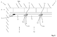
- FIG. 2 shows the ceiling covering 1 off FIG. 1 but relocated according to the inventive method.
- an adhesive 14 is arranged in the region of the locking profiles 12 in the region of the locking profiles 12 in the region of the locking profiles 12 in the region of the locking profiles 12 hiss the panels 2 of the first row of panels 5 and the panels 2 of the second row of panels 13, an adhesive 14 is arranged.
- a force occurring in the region on the panels 2 of the first row of panels 5 (represented by an arrow) is thereby transferred to the panels 2 of the second row of panels 13 in a particularly effective manner.
- the panels of the first row of panels can not slip out of the locking connection. The occurrence of a domino effect is prevented.
- the protection against the occurrence of a domino effect can be significantly improved by the transverse-side locking connections (not shown here) between the transverse sides of the panels 2 as Verrieglungsprofil 12 with separate locking bodies (not shown) are formed.
- a further safeguard against the occurrence of the domino effect can be achieved by an interval bonding (not shown here) in which, starting from the last glued-on panel row, here the second row of panels 13, each further fourth, fifth and / or sixth panel row (not shown here) is glued to her subsequent panel row.
- an interval bonding (not shown here) in which, starting from the last glued-on panel row, here the second row of panels 13, each further fourth, fifth and / or sixth panel row (not shown here) is glued to her subsequent panel row.
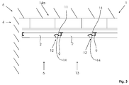
- FIG. 2 largely corresponding embodiment shows FIG. 3 , in which the fastening means engages in a recess, here a groove, which is arranged not in the back of the panel but in the longitudinal edge of the panel.
- the groove can already be arranged at the factory. Alternatively and for example. With a necessary adjustment of the width of the first / last row of panels, the recess can also be arranged on site.
Landscapes
- Engineering & Computer Science (AREA)
- Architecture (AREA)
- Civil Engineering (AREA)
- Structural Engineering (AREA)
- Life Sciences & Earth Sciences (AREA)
- Wood Science & Technology (AREA)
- Finishing Walls (AREA)
Abstract
Description
- Die Erfindung betrifft ein Verlegeverfahren zum Erstellen eines Decken- und/oder Wandbelages mit Paneelen und einen Decken- und/oder Wandbelag mit Paneelen.
- Um die Oberflächenoptik einer Wand oder Decke zu verbessern, werden Paneele als Wand-und/ oder Deckenbelag eingesetzt. Diese bieten zudem den Vorteil, dass von ihnen Installationsvorrichtungen eines Raumes verdeckt werden können.
- Die Paneele umfassen häufig Holzwerkstoffe, die mit einer dekorativen oder leicht zu bearbeitenden Oberflächenbeschichtung versehen sind. Die Kanten der zu Platten aufgetrennten Holzwerkstoffe sind entweder zum stumpfen aneinander Anordnen vorgesehen oder es sind Verbindungsprofile an den Kanten angebracht, um die einzelnen Paneele eines Oberflächenbelags untereinander zu verbinden.
- Bei den Verbindungsprofilen sind insbesondere Nut-Feder-Verbindungen bekannt. Moderne Paneele weisen dagegen an den Kanten zueinander korrespondierende Verriegelungsprofile auf, so dass die Paneele klebemittelfrei untereinander verbunden werden können. Die Verriegelungsprofile verbessern gegenüber den herkömmlichen Nut-Feder-Verbindungen bzw. dem stumpfen Aneinanderlegen die Oberflächenbündigkeit und gewährleisten, dass zwischen den Paneelen kein Oberflächenversatz in der Belagsebene und keine unbeabsichtigten Lücken zwischen den Paneelen auftreten. Zudem erleichtern die Verriegelungsverbindungen die Verlegung der Paneele erheblich.
- Die Befestigung der Wand- und/oder Deckenpaneele erfolgt üblicherweise direkt auf der Decken- oder Wandoberfläche oder auf entsprechenden vor oder an der Wand oder Decke angeordneten Untergründen, wie Ständerwerken, Abhängevorrichtungen oder anderweitigen Vorrichtungen zum Anordnen der Paneele.
- Insbesondere bei Wand- oder Deckenbelägen, die auch Holzwerkstoffe umfassen, sind zum Abpuffern von Schwind- und Quellbewegungen der Holzwerkstoffe Dehnungsfugen u.ä. vorgesehen, damit durch Schwind- oder Quellbewegungen im Holz auftretende Spannungen ausgeglichen werden können.
- An den verlegten Oberflächenbelegen aus Paneelen können unterschiedliche Kräfte angreifen, die zum Abfallen einzelner Paneele oder größerer Paneelabschnitte führen. Insbesondere bei dem Ablösen von Paneelen einer ersten Paneelreihe kann aufgrund der Verriegelungsvorrichtung ein Dominoeffekt eintreten, durch den bereits ein einzelnes abfallendes Paneel große Bereiche des gesamten Belages oder den gesamten Belag mit ablöst.
- Der Erfindung liegt somit die Aufgabe zugrunde, einen Decken- und/oder Wandbelag und ein besonders einfaches Verlegeverfahren zum Erstellen eines Decken- und/oder Wandbelages aus Paneelen bereitzustellen, mit dem eine erhöhte Sicherheit gegen das Lösen des Decken- und/oder Wandbelages gewährleistet wird.
- Die Erfindung löst die Aufgabe durch ein Verlegeverfahren mit den Merkmalen des Anspruchs 1 und einen Decken- und Wandbelag mit den Merkmalen des Anspruchs 6. Vorteilhafte Weiterbildungen der Erfindung sind in den abhängigen Ansprüchen angegeben. Dabei sind die beschriebenen Merkmale für sich oder in beliebiger Kombination grundsätzlich Gegenstand der Erfindung unabhängig von ihrer Zusammenfassung in den Ansprüchen oder deren Rückbeziehung.
- Das erfindungsgemäße Verlegeverfahren zum Herstellen eines Decken- und/oder Wandbelages aus Paneelen weist die Schritte auf: Anordnen einer Vielzahl von Paneelen an einer vorhandenen Wand oder Decke, wobei die Paneele in Reihen angeordnet und mittels korrespondierender Verriegelungsprofile im Bereich der Längsseiten und Querseiten untereinander verbunden werden, wobei vor einem längsseitigen Verbinden der Paneele einer zweiten Paneelreihe mit den Paneelen einer ersten Paneelreihe ein Klebemittel im Bereich der längsseitigen Verriegelungsprofile angeordnet wird, so dass mit dem längsseitigen Verbinden der Paneele zusätzlich zur Verriegelungsverbindung eine Klebeverbindung im Bereich der längsseitigen Verriegelungsprofile erzeugt wird.
- Das Problem des Dominoeffekts tritt insbesondere dann auf, wenn sich ein oder mehrere Paneele aus der ersten Verlegereihe eines Wand- oder Deckenbelages unbeabsichtigt oder ggf. unkontrolliert lösen und aufgrund der Verriegelungsverbindung an den Paneelkanten die weiteren Paneelreihen des Oberflächenbelages mit ablösen.
- Das Ablösen einzelner Paneele erfolgt üblicherweise durch den Einfluss nicht erwarteter Kräfte auf diese. So kann bspw. eine nicht korrekte Befestigung eines einzelnen Paneels aus der ersten Paneelreihe das Lösen und Abfallen der ersten und weiterer Paneelreihen bewirken. Aufgrund der erfinderischen angeordneten zusätzlichen Klebeverbindung in den - an sich klebemittelfreien - Verriegelungsprofilen entriegelt sich das abfallende Paneel jedoch nicht aus dem längsseitigen Verriegelungsprofil, sondern die Verriegelungsverbindung mit dem Paneel der zweiten Reihe bleibt erhalten, wodurch ein Abfallen des Paneels und weiterer Paneele sicher verhindert wird. D.h., die auf das sich lösende Paneel einwirkenden Kräfte werden unerwarteter Weise auf mehrere Paneele nämlich auch auf die Paneele der zweiten Paneelreihe übertragen. Bei einer Verwendung von im Verriegelungsprofil eingreifenden Verbindungsmitteln zum Verbinden der Paneele mit der Wand oder Decke kann zudem ein Lösen der Paneele vom Verbindungsmittel verhindert werden. Der erfinderische Decken- und Wandbelag und das erfinderische Verlegeverfahren verhindern somit durch die zusätzliche Klebeverbindung auf überraschend einfache Weise das Auftreten von Dominoeffekten beim Ablösen eines Paneels aus einem Decken- und/oder Wandbelag.
- Unter Wand- und Deckenbelägen sind vom Rauminneren aus sichtbare Beschichtungen, Verkleidungen, Beläge (auf/an den Wänden und Decken) zu verstehen.
- Diese können mithilfe von Verbindungsmitteln direkt mit der Wand oder der Decke oder mittels der Verbindungsmittel mit einem auf oder vor der Wand- oder Deckenoberfläche angeordneten Untergrund verbunden werden.
- Dementsprechend werden im Zusammenhang mit der Erfindung unter einer Wand oder Decke die direkte Wand- oder Deckenoberfläche oder die auf oder vor der Wand- oder Deckenoberfläche angeordneten Untergründe, wie Ständerwerke, Abhängevorrichtungen, Schienensystemen oder anderweitige Vorrichtungen zum Anordnen der Paneele verstanden.
- Die Paneele umfassen zumindest eine Holzwerkstoffplatte, wie eine Spanplatte oder eine Faserplatte (bspw. MDF-Platte) oder auch eine mineralfasergebundene Platte. An die Außenkanten der Holzwerkstoffplatte sind korrespondierende Verriegelungsprofile angearbeitet. Dies können bspw. Drehprofile und/oder Schwenkprofile oder auch vertikale Rastprofile sein.
- Die Verriegelungsprofile an den Längsseiten und Querseiten der Holzwerkstoffplatte sind besonders als Rastprofile, das heißt zum gegenseitigen Verriegeln, ausgebildet. Dabei sind die Profile insbesondere als Drehprofile und/oder Schwenkprofile oder als vertikale Rastprofile ausgebildet. Bei rechtwinkligen Paneelen wird unter der Querseite die kürzere und unter der Längsseite die längere der Seitenkanten verstanden.
- Unter einem vertikalen Rastprofil wird ein Verriegelungsprofil verstanden, bei dem die beiden Verriegelungsprofile der zu verbindenden Paneele in einer senkrecht zur Oberseite zeigenden Richtung ineinander bringbar sind, entsprechend bspw. einem Druckknopfprofil. Zudem werden unter vertikalen Rastprofilen Verriegelungsprofile verstanden, bei denen die beiden zu verbindenden Verriegelungsprofile (scherenartig) ineinander klappbar sind und zwar um eine 90 Grad zur Längsachse der (ineinander bringbaren) Verriegelungsprofile zeigende Richtung. Vertikale Rastprofile sind insbesondere keine Drehprofile und/oder Schwenkprofile bzw. keine in Plattenebene ineinanderschiebbare Verriegelungsprofile.
- Unter einem Drehprofil und/oder Schwenkprofil (im Weiteren auch Dreh-Schwenk-Profile) können demnach Verriegelungsprofile verstanden werden, bei denen der Verriegelungsvorgang der miteinander zu verbindenden korrespondierenden Verriegelungsprofile eine Drehbewegung und/oder eine Schwenkbewegung um eine sich in Profilrichtung erstreckende Längsachse umfasst.
- Vorzugsweise sind die Verriegelungsprofile an den Längsseiten und den Querseiten korrespondierend zueinander, so dass ein erstes Paneel mit einer Querseite in eine Längsseite eines zweiten Paneels eingerastet werden kann. Hierzu können die Verriegelungsprofile bspw. als Dreh-Schwenk-Profil oder vertikales Rastprofil ausgebildet sein. Bei der Ausführung von bspw. rechteckigen Paneelen können somit eine Vielzahl von unterschiedlichen Verlegemustern (bspw. Querseite an Längsseite) verwirklicht werden.
- Alternativ weisen jeweils die Querseiten korrespondierende Verriegelungsprofile, bspw. vertikale Rastprofile, und jeweils die Längsseiten korrespondierende Verriegelungsprofile, bspw. Drehprofile und/oder Schwenkprofile, auf, wodurch insbesondere die Montage der Paneele im Wand- oder Deckenbereich deutlich erleichtert wird.
- Beim Verlegeverfahren kann eine erste Paneelreihe (zumindest teilweise) an eine Übergangsseite (Bereich einer Raumecke) zwischen Decke und Wand, zwischen zwei Wänden bzw. zwischen Wand und Boden angeordnet werden. Hierfür wird ein erstes Paneel an der zu belegenden Decke oder Wand befestigt, ausgerichtet bspw. mit einer längsseitigen Federseite, insbesondere mit einer längsseitigen oberen Nutwangenseite, in Richtung der an die zu belegende Decke oder Wand angrenzenden Wand oder Decke bzw. des angrenzenden Bodens
- Weitere Paneele werden querseitig mit dem bereits befestigten Paneel über die querseitigen Verriegelungsverbindungen verbunden und ebenfalls an der zu belegende Decke oder Wand befestigt, bis eine erste Paneelreihe (oder zumindest Teile hiervon) an der Wand oder Decke vorhanden sind.
- Zum Befestigen der einzelnen Paneele der ersten und/oder letzten Paneelreihe kann bspw. an der zur Übergangsseite zeigenden Paneelseite ein hierfür vorgesehenes Befestigungsmittel, bspw. eine hierfür vorgesehene Kralle oder ein Clip (bspw. schwimmende Verlegung möglich) verwendet werden, welches an dem jeweiligen Paneel angeordnet, bspw. angeschraubt, angeklebt und/oder angenagelt wird. Auch kann das Befestigungsmittel bspw. an einer oberen Nutwange oder einer Nut des Paneels angreifen und mit der Wand/Decke verbunden werden. Dabei kann das Befestigungsmittel an einem vor oder an der Wand oder Decke angeordnetem Schienensystem angeordnet werden. Insbesondere für eine zumindest teilweise (in eine Horizontalrichtung beweglich) oder eine vollständige (in zwei Horizontalrichtungen) schwimmende Verlegung der ersten und/oder letzten Paneelreihe (bzw. Paneele im Bereich von Ausnehmungen) kann das Befestigungsmittel zudem beweglich an dem Schienensystem und/oder dem Paneel befestigt werden. Alternativ können die Paneele der ersten Reihe an der Übergangsseite mittels eines Nagels/ einer Schraube am Untergrund befestigt werden.
- Zum Befestigen des Paneels an der gegenüberliegenden Längsseite wird vorzugsweise ein Verbindungsmittel im Bereich des längsseitigen Verriegelungsprofils, insbesondere einer unteren Nutwange des längsseitigen Verriegelungsprofils, angeordnet. Hierfür kann bspw. ein Montageelement mit Montagelasche verwendet werden. Dabei ist die Montagelasche bspw. zum Eingriff im Bereich einer unteren Nutwange des längsseitigen Verriegelungsprofils ausgebildet. Das Verbindungsmittel kann auch für die weiteren Paneelreihen verwendet werden. Die letzte Paneelreihe, das heißt, die den Wand- und/oder Deckenbelag abschließende Paneelreihe, wird bevorzugt wieder mittels des Befestigungsmittels mit dem Untergrund verbunden. Das Befestigungsmittel kann ferner bei Ausnehmungen in dem Oberflächenbelag oder auch bei Dehnungsfugen und Neuansätzen in dem Oberflächenbelag verwendet werden.
- Das Verbindungsmittel ist insbesondere als Montageelement mit Montagelasche ausgebildet. Dieses kann mit einer Unterkonstruktion, bspw. einem Schienensystem, verbunden und anschließend mit der Montagelasche auf die untere Nutwange geschoben zu werden, wodurch bspw. eine schwimmende Verlegung des Belages ermöglicht wird.
- Alternativ kann das Verbindungsmittel abhängig von seiner Ausgestaltung auch zuerst mit dem Paneel verbunden und anschließend mit dem Untergrund befestigt werden. Das Verbindungsmittel gewährleistet in besonders einfacher Weise eine vorteilhafte schwimmende Verlegung des Decken- und/oder Wandbelages. Zudem ist es üblich, den Wand- und Deckenbelag mit einer Schattenfuge, d.h. einem Abstand zu dem angrenzenden Wand-, Decken- und/oder Bodenbereich, zu verlegen, so dass eine ungehinderte Bewegung des Decken- und/oder Wandbelages erfolgen kann.
- Zum Anordnen der zweiten Paneelreihe wird zuerst ein Klebemittel im Bereich der längsseitigen Verriegelungsprofile eingebracht. Das Klebemittel kann im Verriegelungsprofil der ersten (der bereits montierten) Paneelreihe und/oder in dem Verriegelungsprofil der Paneele der zweiten Paneelreihe angeordnet werden. Anschließend wird das erste Paneel der zweiten Paneelreihe längsseitig mit einem Paneel der ersten Paneelreihe über die längsseitigen Verriegelungsprofile verbunden. Nachfolgend wird ein Verbindungsmittel an diesem Paneel der zweiten Paneelreihe angeordnet, das bspw. bereits mit der Decke oder der Wand verbunden ist.
- Für das zweite Paneel der zweiten Paneelreihe wird erneut das Klebemittel am längsseitigen Verriegelungsprofil eingebracht und anschließend wird das zweite Paneel mittels der längsseitigen Verriegelungsprofile mit der ersten Paneelreihe und mittels der querseitigen Verriegelungsprofile mit dem ersten Paneel der zweiten Paneelreihe verbunden und mindestens ein Verbindungsmittel angeordnet.
- Die weitere Verlegung der Paneele der zweiten Paneelreihe erfolgt analog hierzu. Die weiteren Paneelreihen werden ebenfalls dementsprechend verlegt, jedoch ohne die Zugabe von Klebemitteln.
- Das Herstellen der Klebeverbindung ist selbstverständlich abhängig von der entsprechenden Topfzeit des Klebemittels, so dass die Klebeverbindung üblicherweise nicht gleichzeitig mit der Verriegelungsverbindung, sondern erst mit dem Abbinden des Klebers erzeugt wird. Das Klebemittel kann bspw. ein flüssig einbringbares Klebemittel, bspw. ein Holzleim, sein. Besonders geeignete Klebemittel umfassen zudem bspw.1-Komponenten-Polyurethan, 2-Komponenten-Polyurethan, vorzugsweise fugenfüllendes PVAc Klebemittel und/oder Phenolformaldehyd.
- Die Anordnung des Klebemittels erfolgt, vorzugsweise und die Verlegung erleichternd, im Bereich des Verriegelungsprofils des bereits an der Wand oder Decke angeordneten Paneels. Alternativ oder ergänzend kann das Klebemittel jedoch auch im Bereich der Verriegelungsprofile der noch zu Verlegenden Paneel erfolgen.
- Das Klebemittel wird insbesondere ausschließlich im Bereich der längsseitigen Verriegelungsprofile und insbesondere nicht im Bereich der Verbindungsmittel angeordnet. Eine Klebemittelanordnung im Bereich der querseitigen Verrieglungsprofile erfolgt nicht.
- Des Weiteren können die Paneele eine Deckschicht aufweisen, die bspw. als Vollholzschicht ausgebildet ist. Vorzugsweise ist die Deckschicht jedoch als auf die Oberfläche der Holzwerkstoffplatte aufgetragene Schicht aus PVC, PE, PP, Polyester, PU, als Schichtstoff, HPL, DPL, CPL, Folie, Acrylfolie und/oder als auf die Oberfläche aufgedruckte Lack- und/oder Kunstharzschicht ausgebildet, die bspw. im Digitaldruck aufgetragen wird. Die Deckschicht kann zudem sämtliche für das Auftragen der Deckschicht oder einer Dekorschicht notwendigen Hilfsschichten, wie bspw. Klebschichten, Grundierungen, Spachtelschichten usw., umfassen.
- Vorteilhaft kann zudem (außenseitig) eine (insbesondere transparente) Nutzschicht und/oder Strukturschicht oder eine strukturierte Nutzschicht zur Verbesserung der Oberflächenbeständigkeit des Paneels vor äußeren Einflüssen bzw. zur optischen Aufwertung und/oder haptischen Ausbildung der Oberfläche angeordnet sein. Die Nutzschicht und/oder Strukturschicht kann bspw. als Kunstharzschicht oder Overlay jeweils flüssig oder fest aufgetragen werden. Insbesondere wird die Nutzschicht und/oder Strukturschicht mittels eines schichtbildenden digitalen Druckverfahrens aufgetragen. Einzelne Schichten, wie bspw. eine Strukturschicht, können nur abschnittsweise aufgetragen sein, um eine haptische, bspw. auf das Dekor abgestimmte, negative oder positive Oberflächenstruktur zu erzeugen.
- Um die Ausfallsicherung, also die Sicherung des Decken- und/oder Wandbelages gegen das Lösen und/oder Abfallen weiter zu erhöhen, ist nach einer Weiterbildung der Erfindung vorgesehen, dass vor einem längsseitigen Verbinden der Paneele einer dritten Paneelreihe mit den Paneelen der zweiten Paneelreihe das Klebemittel im Bereich der längsseitigen Verriegelungsprofile angeordnet wird.
- Diese zusätzliche Verklebung einer weiteren Paneelreihe erhöht die Abfallsicherung erheblich, so dass selbst bei hohen einwirkenden Kräften auf einzelne Paneele der ersten Paneelreihe ein Dominoeffekt und somit ein Abfallen großer Teile des Decken- und Wandbelages sicher verhindert wird.
- Für eine ebenfalls die Ausfallsicherung steigernde Wirkung ist nach einer Weiterbildung der Erfindung vorgesehen, dass die Paneelreihen längsseitig intervallartig miteinander verklebt werden, wobei insbesondere jede weitere vierte, fünfte und/oder sechste Paneelreihe mit einer ihr nachfolgenden Paneelreihe längsseitig verklebt wird. Hierdurch wird insbesondere ein auftretender Dominoeffekt unterbrochen.
- Unter intervallartig ist somit zu verstehen, dass nicht alle Paneelreihen eines Decken- und Wandbelages miteinander verklebt werden, sondern dass jeweils zwischen den verklebten Paneelreihen nicht verklebte Paneelreihen vorhanden sind, die ausschließlich über die Verriegelungsprofile mit ihren benachbarten Paneelreihen gekoppelt sind. Dabei hat sich herausgestellt, dass insbesondere jede vierte, fünfte und/oder sechste Paneelreihe besonders dazu geeignet ist, größere Ablösevorgänge des Wandbelages von einer Decke oder Wand zu verhindern.
- Um bspw. die Ausfallsicherung noch weiter zu erhöhen und zudem das Verlegen der Paneele deutlich zu vereinfachen, ist nach einer Weiterbildung der Erfindung vorgesehen, dass das querseitige Verbinden von zwei Paneelen einer Paneelreihe unter Herstellung einer Verriegelungsverbindung mittels an den Querseiten der beiden Paneele angeordneten korrespondierenden Verriegelungsprofilen erfolgt, wobei beim Herstellen der querseitigen Verriegelungsverbindung ein separater Verriegelungskörper in dem Verriegelungsprofil des ersten Paneels und dem Verriegelungsprofil des zweiten Paneels eingreift. Dabei führt überraschenderweise gerade ein querseitiges Verriegelungsprofil mit separatem Verriegelungskörper in Kombination mit der Verklebung einzelner Paneelreihen untereinander zu einer deutlichen Erhöhung der Ausfallsicherung.
- Unter dem Eingreifen des Verriegelungskörpers wird verstanden, dass der separate Verriegelungskörper zumindest teilweise in Abschnitte der an dem Paneel angeordneten Verriegelungsprofile eindringt. Das heißt, der Verriegelungskörper ist im verriegelten Zustand in beiden Verriegelungsprofilen der zu verriegelnden Paneele angeordnet. Dabei kann der Verriegelungskörper auch bereits in einem der Paneele angeordnet sein und beim Anordnen des zweiten Paneels, d. h. beim Verriegelungsvorgang über die korrespondierenden Verriegelungsprofile, zusätzlich in das Verriegelungsprofil des anderen Paneels eingreifen.
- Unter einem separaten Verriegelungskörper wird ein nicht aus dem Paneel gebildetes separates Bauteil verstanden, das in den Profilbereich eingreift und zwei Paneele aneinander verriegelt. Dabei verhindert der separate Verriegelungskörper insbesondere einen Höhenversatz der sichtbaren Paneeloberflächen und/oder einen Spalt zwischen den Paneelen.
- Sowohl die Drehprofile und/oder Schwenkprofile als auch die vertikalen Rastprofile können mit oder ohne separaten Verriegelungskörper ausgebildet sein. Auch sind vertikale Rastprofile an den Längsseiten der Paneele anordbar.
- Weiter wird die Aufgabe der Erfindung gelöst durch einen Decken- und/oder Wandbelag mit Paneelen mit einer Vielzahl von miteinander verbundenen Paneelreihen aus einzelnen Paneelen, wobei die einzelnen Paneele mittels querseitig und längsseitig angeordneter korrespondierender Verriegelungsprofile untereinander eine Verriegelungsverbindung ausbilden und zumindest zwischen den Paneelen einer ersten Paneelreihe und den Paneelen einer zweiten Paneelreihe im Bereich der längsseitigen Verriegelungsprofile ein Klebemittel vorhanden ist, das zusätzlich zu der Verriegelungsverbindung eine Klebeverbindung ausbildet. Der erfinderische Decken- und/oder Wandbelag verhindert das Auftreten von Dominoeffekten beim Lösen einzelner Paneele. Weiter können die Paneele des Deckenbelags bspw. als Akustikpaneel, insbesondere mit einer Oberfläche mit Ausnehmungen und/oder einem Absorber auf der Rückseite des Paneels ausgebildet sein.
- Im Weitern wird die Erfindung anhand von Ausführungsbeispielen näher erläutert. Es zeigen:
- Fig. 1
- schematisch in einem Querschnitt einen Deckenbelag aus Paneelen, verlegt nach einem Standardverfahren mit einem auftretenden Dominoeffekt;
- Fig. 2
- schematisch in einem Querschnitt den Deckenbelag aus
Figur 1 , verlegt nach dem erfinderischen Verfahren; - Fig. 3
- schematisch in einem Querschnitt die Ausführungsform aus
Figur 2 mit einem alternativen Befestigungsmittel. -
Figur 1 zeigt schematisch in einem Querschnitt einen auftretenden Dominoeffekt bei einem, weitestgehend schwimmend verlegten, Deckenbelag 1 mit Paneelen 2. Die Paneele 2 wurden auf einer an der Decke 3 angeordneten Unterkonstruktion 4 verlegt, die als abgehängtes Schienensystem ausgebildet ist. Die erste Paneelreihe 5 wurde im Bereich des Decken-Wandüberganges 6 längsseitig mittels eines Befestigungsmittels 7, hier einer Spezialkralle, rückseitig befestigt. Die Spezialkralle greift in eine rückseitig am Paneel 2 angeordnete Verbindungsmittelaufnahme (hier nicht dargestellt) ein und ist mit der Unterkonstruktion 4 verbunden. An der gegenüberliegenden Längsseite 8 der Paneele 2 der ersten Paneelreihe 5 wurden für jedes Paneel 2 zwei (alternativ 3 oder 4) Verbindungsmittel 9 an der Unterkonstruktion 4 beweglich angeordnet und mit den Paneelen 2 verbunden. Die Verbindungsmittel 9 sind als Montageelemente mit einer Montagelasche 10 ausgebildet. Die Montagelasche 10 greift im Bereich einer als Verbindungsmittelaufnahme ausgebildeten unteren Nutwange 11 des längsseitigen Verriegelungsprofils 12 an. - Die Paneele 2 der zweiten Paneelreihe 13 wurden über die längsseitigen Verriegelungsprofile 12 mit den Paneelen 2 der ersten Paneelreihe 5, unter Ausbildung einer Verriegelungsverbindung, verbunden. Die Paneele 2 einer Paneelreihe 5, 13 wurden nacheinander verlegt und an den Querseiten (hier nicht dargestellt) mittels als vertikale Rastprofile (hier nicht dargestellt) ausgebildeten Verriegelungsprofilen (hier nicht dargestellt) untereinander verbunden.
- Bei einem (beabsichtigten oder unbeabsichtigten) Ablösen der Paneele 2 der ersten Paneelreihe 5 bspw. von der Spezialkralle tritt der Dominoeffekt auf. Das sich an der Übergangsseite 6 ablösende Paneel 2 zieht aufgrund der Verriegelungsverbindung an den Paneelen 2 der zweiten Paneelreihe 13 und rutscht aus der Verriegelungsverbindung und dem Verbindungsmittel 9 heraus. Aufgrund der Verbindung über die Verriegelungsprofile 12 lösen sich dementsprechend auch die Paneele 2 der zweiten Paneelreihe 13. Die weiteren Paneelreihen (hier nicht dargestellt) werden analog abgelöst, so dass ein Dominoeffekt auftritt.
-
Figur 2 zeigt den Deckenbelag 1 ausFigur 1 jedoch verlegt nach dem erfinderischen Verfahren. Im Bereich der Verriegelungsprofile 12 zischen den Paneelen 2 der ersten Paneelreihe 5 und den Paneelen 2 der zweiten Paneelreihe 13 ist ein Klebmittel 14 angeordnet. - Eine im Bereich an den Paneelen 2 der ersten Paneelreihe 5 auftretende Kraft (durch einen Pfeil dargestellt) wird dadurch besonders effektiv auf die Paneele 2 der zweiten Paneelreihe 13 übertragen. Zudem können die Paneele der ersten Paneelreihe nicht aus der Verriegelungsverbindung rutschen. Das Auftreten eines Dominoeffekts wird verhindert.
- Die Sicherung gegen das Auftreten eines Dominoeffekts kann überraschenderweise zusätzlich deutlich verbessert werden, indem die querseitigen Verriegelungsverbindungen (hier nicht dargestellt) zwischen den Querseiten der Paneele 2 als Verrieglungsprofil 12 mit separaten Verriegelungskörpern (hier nicht dargestellt) ausgebildet sind.
- Eine weitere Sicherung gegen das Auftreten des Dominoeffektes kann durch eine Intervallverklebung (hier nicht dargestellt) erreicht werden, bei der ausgehend von der letzten verklebten Paneelreihe, hier die zweite Paneelreihe 13, jede weitere vierte, fünfte und/oder sechste Paneelreihe (hier nicht dargestellt) mit der ihr nachfolgenden Paneelreihe verklebt wird. Hierdurch wird insbesondere ein in den ersten Paneelreihen auftretender Dominoeffekt sicher unterbrochen.
- Diese zusätzlich zu den Verriegelungsverbindungen der Verriegelungsprofile 12 ausgebildete Klebeverbindungen 14a bewirken einen sicheren Schutz vor einem Dominoeffekt beim Ablösen der Paneele 2.
- Eine der Ausführungsform aus
Figur 2 weitestgehend entsprechende Ausführungsform zeigtFigur 3 , bei der das Befestigungsmittel in eine Ausnehmung, hier eine Nut, eingreift, die nicht rückseitig im Paneel, sondern in der Längskante des Paneels angeordnet ist. Die Nut kann bereits werkseitig angeordnet werden. Alternativ und bspw. bei einer notwendigen Anpassung der Breite der ersten/letzten Paneelreihe kann die Ausnehmung auch bauseitig angeordnet werden. - Obwohl manche Aspekte im Zusammenhang mit einem Verfahren beschrieben wurden, versteht es sich, dass diese Aspekte auch eine Beschreibung der Vorrichtung darstellen, so dass ein Verfahrensschritt oder ein Merkmal eines Verfahrensschrittes auch als Block- oder ein Bauelement einer Vorrichtung zu verstehen ist. Analog dazu stellen Aspekte, die im Zusammenhang mit der Vorrichtung beschrieben wurden, auch eine Beschreibung eines entsprechenden Verfahrensschritts oder ein Merkmal eines Verfahrensschrittes dar.
-
- 1.
- Decken- und Wandbelag
- 2.
- Paneele
- 3.
- Decke
- 4.
- Unterkonstruktion
- 5.
- erste Paneelreihe
- 6.
- Übergang
- 7.
- Befestigungsmittel
- 8.
- Längsseite
- 9.
- Verbindungsmittel
- 10.
- Montagelasche
- 11.
- untere Nutwange
- 12.
- längsseitiges Verriegelungsprofil
- 13.
- zweite Paneelreihe
- 14.
- Klebmittel
- 14a.
- Klebeverbindung
Claims (6)
- Verlegeverfahren zum Erstellen eines Decken- und/oder Wandbelages aus Paneelen (2) mit den Schritten:- Anordnen einer Vielzahl von Paneelen(2) an einer vorhandenen Wand oder Decke (3),- wobei die Paneele (2) in Reihen (5, 13) angeordnet und mittels korrespondierender Verriegelungsprofile (12) im Bereich der Längsseiten und Querseiten untereinander verbunden werden,- dadurch gekennzeichnet, dass- vor einem längsseitigen Verbinden der Paneele (2) einer zweiten Paneelreihe (13) mit den Paneelen (2) einer ersten Paneelreihe (5) ein Klebemittel (14) im Bereich der längsseitigen Verriegelungsprofile (12) angeordnet wird, wobei mit dem längsseitigen Verbinden der Paneele (2) zusätzlich zu der Verriegelungsverbindung eine Klebeverbindung (14a) im Bereich der längsseitigen Verriegelungsprofile (12) erzeugt wird.
- Verlegeverfahren nach Anspruch 1, dadurch gekennzeichnet, dass vor einem längsseitigen Verbinden der Paneele (2) einer dritten Paneelreihe mit den Paneelen (2) einer zweiten Paneelreihe ein Klebemittel (14) im Bereich der längsseitigen Verriegelungsprofile angeordnet wird.
- Verlegeverfahren nach Anspruch 1 oder 2, dadurch gekennzeichnet, dass die Paneelreihen längsseitig intervallartig miteinander verklebt werden, wobei insbesondere jede vierte, fünfte oder sechste Paneelreihe mit der ihr nachfolgenden Paneelreihe längsseitig verklebt wird.
- Verlegeverfahren nach einem der vorhergehenden Ansprüche, dadurch gekennzeichnet, dass der Decken- und/oder Wandbelag schwimmend verlegt wird.
- Verlegeverfahren nach einem der vorhergehenden Ansprüche, gekennzeichnet durch das- querseitige Verbinden von zwei Paneelen (2) einer Paneelreihe (5, 13) unter Herstellung einer Verriegelungsverbindung mittels an den Querseiten der beiden Paneele (2) angeordneten korrespondierenden Verriegelungsprofilen, wobei- beim Herstellen der querseitigen Verriegelungsverbindung ein separater Verriegelungskörper in dem Verriegelungsprofil des ersten Paneels und dem Verriegelungsprofil des zweiten Paneels eingreift.
- Decken- und/oder Wandbelag aus Paneelen(2) mit- einer Vielzahl von miteinander verbundenen Paneelreihen (5, 13) aus einzelnen Paneelen (2), wobei die einzelnen Paneele (2) mittels querseitig und längsseitig angeordneter korrespondierender Verriegelungsprofile (12) untereinander eine Verriegelungsverbindung ausbilden und- zumindest zwischen den Paneelen (2) einer ersten Paneelreihe (5, 13) und den Paneelen (2) einer zweiten Paneelreihe (5, 13) im Bereich der längsseitigen Verriegelungsprofile(12) ein Klebemittel (14) vorhanden ist, das zusätzlich zu der Verriegelungsverbindung eine Klebeverbindung (14a) ausbildet.
Priority Applications (4)
| Application Number | Priority Date | Filing Date | Title |
|---|---|---|---|
| ES16176934T ES2754383T3 (es) | 2016-06-29 | 2016-06-29 | Procedimiento de colocación para fabricar un revestimiento de techo y/o de pared hecho de paneles, así como revestimientos de techo y/o de pared hechos de paneles |
| PT161769344T PT3263798T (pt) | 2016-06-29 | 2016-06-29 | Método de colocação para o fabrico de uma cobertura de teto e/ou de parede constituída por painéis e coberturas de teto e/ou de parede constituídas por painéis |
| PL16176934T PL3263798T3 (pl) | 2016-06-29 | 2016-06-29 | Sposób układania w celu wykonania okładziny sufitowej i/lub ściennej z paneli |
| EP16176934.4A EP3263798B1 (de) | 2016-06-29 | 2016-06-29 | Verlegeverfahren zum herstellen eines decken- und/oder wandbelages aus paneelen und decken- und/oder wandbeläge aus paneelen |
Applications Claiming Priority (1)
| Application Number | Priority Date | Filing Date | Title |
|---|---|---|---|
| EP16176934.4A EP3263798B1 (de) | 2016-06-29 | 2016-06-29 | Verlegeverfahren zum herstellen eines decken- und/oder wandbelages aus paneelen und decken- und/oder wandbeläge aus paneelen |
Publications (2)
| Publication Number | Publication Date |
|---|---|
| EP3263798A1 true EP3263798A1 (de) | 2018-01-03 |
| EP3263798B1 EP3263798B1 (de) | 2019-08-07 |
Family
ID=56368818
Family Applications (1)
| Application Number | Title | Priority Date | Filing Date |
|---|---|---|---|
| EP16176934.4A Active EP3263798B1 (de) | 2016-06-29 | 2016-06-29 | Verlegeverfahren zum herstellen eines decken- und/oder wandbelages aus paneelen und decken- und/oder wandbeläge aus paneelen |
Country Status (4)
| Country | Link |
|---|---|
| EP (1) | EP3263798B1 (de) |
| ES (1) | ES2754383T3 (de) |
| PL (1) | PL3263798T3 (de) |
| PT (1) | PT3263798T (de) |
Citations (3)
| Publication number | Priority date | Publication date | Assignee | Title |
|---|---|---|---|---|
| JP2001081952A (ja) * | 1999-09-10 | 2001-03-27 | Daiken Trade & Ind Co Ltd | 床暖房用床材 |
| US20030024199A1 (en) * | 2001-07-27 | 2003-02-06 | Darko Pervan | Floor panel with sealing means |
| US20100281810A1 (en) * | 2009-05-08 | 2010-11-11 | Carl Ruland | Overlap System For A Flooring System |
Family Cites Families (1)
| Publication number | Priority date | Publication date | Assignee | Title |
|---|---|---|---|---|
| US20040211144A1 (en) * | 2001-06-27 | 2004-10-28 | Stanchfield Oliver O. | Flooring panel or wall panel and use thereof |
-
2016
- 2016-06-29 PL PL16176934T patent/PL3263798T3/pl unknown
- 2016-06-29 ES ES16176934T patent/ES2754383T3/es active Active
- 2016-06-29 EP EP16176934.4A patent/EP3263798B1/de active Active
- 2016-06-29 PT PT161769344T patent/PT3263798T/pt unknown
Patent Citations (3)
| Publication number | Priority date | Publication date | Assignee | Title |
|---|---|---|---|---|
| JP2001081952A (ja) * | 1999-09-10 | 2001-03-27 | Daiken Trade & Ind Co Ltd | 床暖房用床材 |
| US20030024199A1 (en) * | 2001-07-27 | 2003-02-06 | Darko Pervan | Floor panel with sealing means |
| US20100281810A1 (en) * | 2009-05-08 | 2010-11-11 | Carl Ruland | Overlap System For A Flooring System |
Also Published As
| Publication number | Publication date |
|---|---|
| ES2754383T3 (es) | 2020-04-17 |
| PT3263798T (pt) | 2019-11-15 |
| EP3263798B1 (de) | 2019-08-07 |
| PL3263798T3 (pl) | 2020-01-31 |
Similar Documents
| Publication | Publication Date | Title |
|---|---|---|
| EP1476615B1 (de) | Paneel, insbesondere fussdodenpaneel | |
| DE69434539T2 (de) | Schichtplatte für Fussboden | |
| EP1527241B1 (de) | Vorrichtung zum verbinden von zwei plattenförmigen paneelen | |
| DE10159284B4 (de) | Gebäudeplatte, insbesondere Bodenpaneel | |
| DE102010012572B3 (de) | System von wenigstens zwei Paneelen | |
| EP3112545B1 (de) | Akustikpaneel | |
| DE202018006667U1 (de) | Wand- oder Deckenpaneel und Wand- oder Deckenanordnung | |
| EP3321441B1 (de) | Klammersystem für paneele | |
| DE202004021960U1 (de) | Paneele | |
| EP1382774A1 (de) | Fussbodenpaneel | |
| DE202019103690U1 (de) | Paneel | |
| WO2007016978A1 (de) | Flächenbündiges dehnungsprofil | |
| EP3374579B1 (de) | Mechanische verbindung für paneele | |
| EP3754128B1 (de) | Akustikpaneel mit versetzten nuten | |
| EP2955295B1 (de) | Verfahren zum Herstellen eines Paneels | |
| DE102014103176A1 (de) | Belag aus mechanisch miteinander verbindbaren Paneelen | |
| EP2591181B1 (de) | Lochplatten auf Basis von Gips sowie Verfahren zum Verlegen derselben | |
| WO2019180097A1 (de) | Paneel, zweites paneel, paneelverbindung und verfahren zur herstellung der paneelverbindung | |
| DE202015105688U1 (de) | Wandkonstruktion | |
| EP1683929B1 (de) | Verfahren zur Herstellung eines Paneels, insbesondere Fussbodenpaneels, und Paneel, insbesondere Fussbodenpaneel | |
| EP1873326A1 (de) | Profilsystem zur Herstellung der Eckausbildung im Trockenbau | |
| EP3263798B1 (de) | Verlegeverfahren zum herstellen eines decken- und/oder wandbelages aus paneelen und decken- und/oder wandbeläge aus paneelen | |
| EP2795016B1 (de) | Paneel eines fussbodenbelags mit fremdelement | |
| WO2005066432A1 (de) | Einschwenkprofil | |
| DE102005007269A1 (de) | Leisteneckverkleidung |
Legal Events
| Date | Code | Title | Description |
|---|---|---|---|
| PUAI | Public reference made under article 153(3) epc to a published international application that has entered the european phase |
Free format text: ORIGINAL CODE: 0009012 |
|
| STAA | Information on the status of an ep patent application or granted ep patent |
Free format text: STATUS: REQUEST FOR EXAMINATION WAS MADE |
|
| 17P | Request for examination filed |
Effective date: 20170630 |
|
| AK | Designated contracting states |
Kind code of ref document: A1 Designated state(s): AL AT BE BG CH CY CZ DE DK EE ES FI FR GB GR HR HU IE IS IT LI LT LU LV MC MK MT NL NO PL PT RO RS SE SI SK SM TR |
|
| AX | Request for extension of the european patent |
Extension state: BA ME |
|
| STAA | Information on the status of an ep patent application or granted ep patent |
Free format text: STATUS: EXAMINATION IS IN PROGRESS |
|
| 17Q | First examination report despatched |
Effective date: 20180824 |
|
| GRAP | Despatch of communication of intention to grant a patent |
Free format text: ORIGINAL CODE: EPIDOSNIGR1 |
|
| STAA | Information on the status of an ep patent application or granted ep patent |
Free format text: STATUS: GRANT OF PATENT IS INTENDED |
|
| INTG | Intention to grant announced |
Effective date: 20190228 |
|
| GRAS | Grant fee paid |
Free format text: ORIGINAL CODE: EPIDOSNIGR3 |
|
| GRAA | (expected) grant |
Free format text: ORIGINAL CODE: 0009210 |
|
| STAA | Information on the status of an ep patent application or granted ep patent |
Free format text: STATUS: THE PATENT HAS BEEN GRANTED |
|
| AK | Designated contracting states |
Kind code of ref document: B1 Designated state(s): AL AT BE BG CH CY CZ DE DK EE ES FI FR GB GR HR HU IE IS IT LI LT LU LV MC MK MT NL NO PL PT RO RS SE SI SK SM TR |
|
| REG | Reference to a national code |
Ref country code: GB Ref legal event code: FG4D Free format text: NOT ENGLISH |
|
| REG | Reference to a national code |
Ref country code: CH Ref legal event code: EP Ref country code: AT Ref legal event code: REF Ref document number: 1164109 Country of ref document: AT Kind code of ref document: T Effective date: 20190815 |
|
| REG | Reference to a national code |
Ref country code: DE Ref legal event code: R096 Ref document number: 502016005891 Country of ref document: DE |
|
| REG | Reference to a national code |
Ref country code: IE Ref legal event code: FG4D Free format text: LANGUAGE OF EP DOCUMENT: GERMAN |
|
| REG | Reference to a national code |
Ref country code: CH Ref legal event code: NV Representative=s name: PATENTANWALT DIPL.-ING. (UNI.) WOLFGANG HEISEL, CH |
|
| REG | Reference to a national code |
Ref country code: PT Ref legal event code: SC4A Ref document number: 3263798 Country of ref document: PT Date of ref document: 20191115 Kind code of ref document: T Free format text: AVAILABILITY OF NATIONAL TRANSLATION Effective date: 20191106 |
|
| REG | Reference to a national code |
Ref country code: NL Ref legal event code: FP |
|
| REG | Reference to a national code |
Ref country code: SE Ref legal event code: TRGR |
|
| REG | Reference to a national code |
Ref country code: LT Ref legal event code: MG4D |
|
| PG25 | Lapsed in a contracting state [announced via postgrant information from national office to epo] |
Ref country code: FI Free format text: LAPSE BECAUSE OF FAILURE TO SUBMIT A TRANSLATION OF THE DESCRIPTION OR TO PAY THE FEE WITHIN THE PRESCRIBED TIME-LIMIT Effective date: 20190807 Ref country code: HR Free format text: LAPSE BECAUSE OF FAILURE TO SUBMIT A TRANSLATION OF THE DESCRIPTION OR TO PAY THE FEE WITHIN THE PRESCRIBED TIME-LIMIT Effective date: 20190807 Ref country code: BG Free format text: LAPSE BECAUSE OF FAILURE TO SUBMIT A TRANSLATION OF THE DESCRIPTION OR TO PAY THE FEE WITHIN THE PRESCRIBED TIME-LIMIT Effective date: 20191107 Ref country code: LT Free format text: LAPSE BECAUSE OF FAILURE TO SUBMIT A TRANSLATION OF THE DESCRIPTION OR TO PAY THE FEE WITHIN THE PRESCRIBED TIME-LIMIT Effective date: 20190807 Ref country code: NO Free format text: LAPSE BECAUSE OF FAILURE TO SUBMIT A TRANSLATION OF THE DESCRIPTION OR TO PAY THE FEE WITHIN THE PRESCRIBED TIME-LIMIT Effective date: 20191107 |
|
| PG25 | Lapsed in a contracting state [announced via postgrant information from national office to epo] |
Ref country code: RS Free format text: LAPSE BECAUSE OF FAILURE TO SUBMIT A TRANSLATION OF THE DESCRIPTION OR TO PAY THE FEE WITHIN THE PRESCRIBED TIME-LIMIT Effective date: 20190807 Ref country code: IS Free format text: LAPSE BECAUSE OF FAILURE TO SUBMIT A TRANSLATION OF THE DESCRIPTION OR TO PAY THE FEE WITHIN THE PRESCRIBED TIME-LIMIT Effective date: 20191207 Ref country code: AL Free format text: LAPSE BECAUSE OF FAILURE TO SUBMIT A TRANSLATION OF THE DESCRIPTION OR TO PAY THE FEE WITHIN THE PRESCRIBED TIME-LIMIT Effective date: 20190807 Ref country code: GR Free format text: LAPSE BECAUSE OF FAILURE TO SUBMIT A TRANSLATION OF THE DESCRIPTION OR TO PAY THE FEE WITHIN THE PRESCRIBED TIME-LIMIT Effective date: 20191108 Ref country code: LV Free format text: LAPSE BECAUSE OF FAILURE TO SUBMIT A TRANSLATION OF THE DESCRIPTION OR TO PAY THE FEE WITHIN THE PRESCRIBED TIME-LIMIT Effective date: 20190807 |
|
| REG | Reference to a national code |
Ref country code: ES Ref legal event code: FG2A Ref document number: 2754383 Country of ref document: ES Kind code of ref document: T3 Effective date: 20200417 |
|
| PG25 | Lapsed in a contracting state [announced via postgrant information from national office to epo] |
Ref country code: EE Free format text: LAPSE BECAUSE OF FAILURE TO SUBMIT A TRANSLATION OF THE DESCRIPTION OR TO PAY THE FEE WITHIN THE PRESCRIBED TIME-LIMIT Effective date: 20190807 Ref country code: DK Free format text: LAPSE BECAUSE OF FAILURE TO SUBMIT A TRANSLATION OF THE DESCRIPTION OR TO PAY THE FEE WITHIN THE PRESCRIBED TIME-LIMIT Effective date: 20190807 Ref country code: RO Free format text: LAPSE BECAUSE OF FAILURE TO SUBMIT A TRANSLATION OF THE DESCRIPTION OR TO PAY THE FEE WITHIN THE PRESCRIBED TIME-LIMIT Effective date: 20190807 |
|
| PG25 | Lapsed in a contracting state [announced via postgrant information from national office to epo] |
Ref country code: SM Free format text: LAPSE BECAUSE OF FAILURE TO SUBMIT A TRANSLATION OF THE DESCRIPTION OR TO PAY THE FEE WITHIN THE PRESCRIBED TIME-LIMIT Effective date: 20190807 Ref country code: SK Free format text: LAPSE BECAUSE OF FAILURE TO SUBMIT A TRANSLATION OF THE DESCRIPTION OR TO PAY THE FEE WITHIN THE PRESCRIBED TIME-LIMIT Effective date: 20190807 Ref country code: CZ Free format text: LAPSE BECAUSE OF FAILURE TO SUBMIT A TRANSLATION OF THE DESCRIPTION OR TO PAY THE FEE WITHIN THE PRESCRIBED TIME-LIMIT Effective date: 20190807 Ref country code: IS Free format text: LAPSE BECAUSE OF FAILURE TO SUBMIT A TRANSLATION OF THE DESCRIPTION OR TO PAY THE FEE WITHIN THE PRESCRIBED TIME-LIMIT Effective date: 20200224 |
|
| REG | Reference to a national code |
Ref country code: DE Ref legal event code: R097 Ref document number: 502016005891 Country of ref document: DE |
|
| PLBE | No opposition filed within time limit |
Free format text: ORIGINAL CODE: 0009261 |
|
| STAA | Information on the status of an ep patent application or granted ep patent |
Free format text: STATUS: NO OPPOSITION FILED WITHIN TIME LIMIT |
|
| PG2D | Information on lapse in contracting state deleted |
Ref country code: IS |
|
| 26N | No opposition filed |
Effective date: 20200603 |
|
| PG25 | Lapsed in a contracting state [announced via postgrant information from national office to epo] |
Ref country code: SI Free format text: LAPSE BECAUSE OF FAILURE TO SUBMIT A TRANSLATION OF THE DESCRIPTION OR TO PAY THE FEE WITHIN THE PRESCRIBED TIME-LIMIT Effective date: 20190807 |
|
| PG25 | Lapsed in a contracting state [announced via postgrant information from national office to epo] |
Ref country code: MC Free format text: LAPSE BECAUSE OF FAILURE TO SUBMIT A TRANSLATION OF THE DESCRIPTION OR TO PAY THE FEE WITHIN THE PRESCRIBED TIME-LIMIT Effective date: 20190807 |
|
| PG25 | Lapsed in a contracting state [announced via postgrant information from national office to epo] |
Ref country code: LU Free format text: LAPSE BECAUSE OF NON-PAYMENT OF DUE FEES Effective date: 20200629 |
|
| PG25 | Lapsed in a contracting state [announced via postgrant information from national office to epo] |
Ref country code: IE Free format text: LAPSE BECAUSE OF NON-PAYMENT OF DUE FEES Effective date: 20200629 |
|
| PG25 | Lapsed in a contracting state [announced via postgrant information from national office to epo] |
Ref country code: MT Free format text: LAPSE BECAUSE OF FAILURE TO SUBMIT A TRANSLATION OF THE DESCRIPTION OR TO PAY THE FEE WITHIN THE PRESCRIBED TIME-LIMIT Effective date: 20190807 Ref country code: CY Free format text: LAPSE BECAUSE OF FAILURE TO SUBMIT A TRANSLATION OF THE DESCRIPTION OR TO PAY THE FEE WITHIN THE PRESCRIBED TIME-LIMIT Effective date: 20190807 |
|
| PG25 | Lapsed in a contracting state [announced via postgrant information from national office to epo] |
Ref country code: MK Free format text: LAPSE BECAUSE OF FAILURE TO SUBMIT A TRANSLATION OF THE DESCRIPTION OR TO PAY THE FEE WITHIN THE PRESCRIBED TIME-LIMIT Effective date: 20190807 |
|
| PGFP | Annual fee paid to national office [announced via postgrant information from national office to epo] |
Ref country code: SE Payment date: 20220623 Year of fee payment: 7 Ref country code: PT Payment date: 20220628 Year of fee payment: 7 Ref country code: NL Payment date: 20220621 Year of fee payment: 7 |
|
| PGFP | Annual fee paid to national office [announced via postgrant information from national office to epo] |
Ref country code: TR Payment date: 20220624 Year of fee payment: 7 Ref country code: PL Payment date: 20220610 Year of fee payment: 7 Ref country code: BE Payment date: 20220621 Year of fee payment: 7 |
|
| PGFP | Annual fee paid to national office [announced via postgrant information from national office to epo] |
Ref country code: IT Payment date: 20220630 Year of fee payment: 7 Ref country code: ES Payment date: 20220719 Year of fee payment: 7 |
|
| REG | Reference to a national code |
Ref country code: SE Ref legal event code: EUG |
|
| REG | Reference to a national code |
Ref country code: NL Ref legal event code: MM Effective date: 20230701 |
|
| REG | Reference to a national code |
Ref country code: BE Ref legal event code: MM Effective date: 20230630 |
|
| PG25 | Lapsed in a contracting state [announced via postgrant information from national office to epo] |
Ref country code: NL Free format text: LAPSE BECAUSE OF NON-PAYMENT OF DUE FEES Effective date: 20230701 |
|
| PG25 | Lapsed in a contracting state [announced via postgrant information from national office to epo] |
Ref country code: SE Free format text: LAPSE BECAUSE OF NON-PAYMENT OF DUE FEES Effective date: 20230630 Ref country code: BE Free format text: LAPSE BECAUSE OF NON-PAYMENT OF DUE FEES Effective date: 20230630 |
|
| PG25 | Lapsed in a contracting state [announced via postgrant information from national office to epo] |
Ref country code: IT Free format text: LAPSE BECAUSE OF NON-PAYMENT OF DUE FEES Effective date: 20230629 |
|
| REG | Reference to a national code |
Ref country code: ES Ref legal event code: FD2A Effective date: 20240802 |
|
| PG25 | Lapsed in a contracting state [announced via postgrant information from national office to epo] |
Ref country code: ES Free format text: LAPSE BECAUSE OF NON-PAYMENT OF DUE FEES Effective date: 20230630 |
|
| PG25 | Lapsed in a contracting state [announced via postgrant information from national office to epo] |
Ref country code: ES Free format text: LAPSE BECAUSE OF NON-PAYMENT OF DUE FEES Effective date: 20230630 |
|
| PG25 | Lapsed in a contracting state [announced via postgrant information from national office to epo] |
Ref country code: PL Free format text: LAPSE BECAUSE OF NON-PAYMENT OF DUE FEES Effective date: 20230629 |
|
| PG25 | Lapsed in a contracting state [announced via postgrant information from national office to epo] |
Ref country code: PL Free format text: LAPSE BECAUSE OF NON-PAYMENT OF DUE FEES Effective date: 20230629 |
|
| PG25 | Lapsed in a contracting state [announced via postgrant information from national office to epo] |
Ref country code: PT Free format text: LAPSE BECAUSE OF NON-PAYMENT OF DUE FEES Effective date: 20230629 |
|
| PGFP | Annual fee paid to national office [announced via postgrant information from national office to epo] |
Ref country code: CH Payment date: 20250701 Year of fee payment: 10 |
|
| PG25 | Lapsed in a contracting state [announced via postgrant information from national office to epo] |
Ref country code: TR Free format text: LAPSE BECAUSE OF NON-PAYMENT OF DUE FEES Effective date: 20230629 |
|
| REG | Reference to a national code |
Ref country code: CH Ref legal event code: U11 Free format text: ST27 STATUS EVENT CODE: U-0-0-U10-U11 (AS PROVIDED BY THE NATIONAL OFFICE) Effective date: 20260701 |
|
| PGFP | Annual fee paid to national office [announced via postgrant information from national office to epo] |
Ref country code: GB Payment date: 20260623 Year of fee payment: 11 |
|
| PGFP | Annual fee paid to national office [announced via postgrant information from national office to epo] |
Ref country code: DE Payment date: 20260624 Year of fee payment: 11 |
|
| PGFP | Annual fee paid to national office [announced via postgrant information from national office to epo] |
Ref country code: AT Payment date: 20260618 Year of fee payment: 11 |
|
| PGFP | Annual fee paid to national office [announced via postgrant information from national office to epo] |
Ref country code: FR Payment date: 20260623 Year of fee payment: 11 |