EP3263304A1 - Verfahren zur herstellung von langfaser verstärktem verbundwerkstoff - Google Patents
Verfahren zur herstellung von langfaser verstärktem verbundwerkstoff Download PDFInfo
- Publication number
- EP3263304A1 EP3263304A1 EP17157724.0A EP17157724A EP3263304A1 EP 3263304 A1 EP3263304 A1 EP 3263304A1 EP 17157724 A EP17157724 A EP 17157724A EP 3263304 A1 EP3263304 A1 EP 3263304A1
- Authority
- EP
- European Patent Office
- Prior art keywords
- hole plate
- hole
- composite material
- fiber
- manufacturing
- Prior art date
- Legal status (The legal status is an assumption and is not a legal conclusion. Google has not performed a legal analysis and makes no representation as to the accuracy of the status listed.)
- Granted
Links
Images




Classifications
-
- D—TEXTILES; PAPER
- D06—TREATMENT OF TEXTILES OR THE LIKE; LAUNDERING; FLEXIBLE MATERIALS NOT OTHERWISE PROVIDED FOR
- D06B—TREATING TEXTILE MATERIALS USING LIQUIDS, GASES OR VAPOURS
- D06B3/00—Passing of textile materials through liquids, gases or vapours to effect treatment, e.g. washing, dyeing, bleaching, sizing, impregnating
- D06B3/04—Passing of textile materials through liquids, gases or vapours to effect treatment, e.g. washing, dyeing, bleaching, sizing, impregnating of yarns, threads or filaments
- D06B3/06—Passing of textile materials through liquids, gases or vapours to effect treatment, e.g. washing, dyeing, bleaching, sizing, impregnating of yarns, threads or filaments individually handled
-
- B—PERFORMING OPERATIONS; TRANSPORTING
- B29—WORKING OF PLASTICS; WORKING OF SUBSTANCES IN A PLASTIC STATE IN GENERAL
- B29B—PREPARATION OR PRETREATMENT OF THE MATERIAL TO BE SHAPED; MAKING GRANULES OR PREFORMS; RECOVERY OF PLASTICS OR OTHER CONSTITUENTS OF WASTE MATERIAL CONTAINING PLASTICS
- B29B15/00—Pretreatment of the material to be shaped, not covered by groups B29B7/00 - B29B13/00
- B29B15/08—Pretreatment of the material to be shaped, not covered by groups B29B7/00 - B29B13/00 of reinforcements or fillers
- B29B15/10—Coating or impregnating independently of the moulding or shaping step
- B29B15/12—Coating or impregnating independently of the moulding or shaping step of reinforcements of indefinite length
- B29B15/122—Coating or impregnating independently of the moulding or shaping step of reinforcements of indefinite length with a matrix in liquid form, e.g. as melt, solution or latex
- B29B15/125—Coating or impregnating independently of the moulding or shaping step of reinforcements of indefinite length with a matrix in liquid form, e.g. as melt, solution or latex by dipping
-
- B—PERFORMING OPERATIONS; TRANSPORTING
- B05—SPRAYING OR ATOMISING IN GENERAL; APPLYING FLUENT MATERIALS TO SURFACES, IN GENERAL
- B05D—PROCESSES FOR APPLYING FLUENT MATERIALS TO SURFACES, IN GENERAL
- B05D7/00—Processes, other than flocking, specially adapted for applying liquids or other fluent materials to particular surfaces or for applying particular liquids or other fluent materials
- B05D7/20—Processes, other than flocking, specially adapted for applying liquids or other fluent materials to particular surfaces or for applying particular liquids or other fluent materials to wires
-
- B—PERFORMING OPERATIONS; TRANSPORTING
- B29—WORKING OF PLASTICS; WORKING OF SUBSTANCES IN A PLASTIC STATE IN GENERAL
- B29C—SHAPING OR JOINING OF PLASTICS; SHAPING OF MATERIAL IN A PLASTIC STATE, NOT OTHERWISE PROVIDED FOR; AFTER-TREATMENT OF THE SHAPED PRODUCTS, e.g. REPAIRING
- B29C70/00—Shaping composites, i.e. plastics material comprising reinforcements, fillers or preformed parts, e.g. inserts
-
- D—TEXTILES; PAPER
- D06—TREATMENT OF TEXTILES OR THE LIKE; LAUNDERING; FLEXIBLE MATERIALS NOT OTHERWISE PROVIDED FOR
- D06B—TREATING TEXTILE MATERIALS USING LIQUIDS, GASES OR VAPOURS
- D06B3/00—Passing of textile materials through liquids, gases or vapours to effect treatment, e.g. washing, dyeing, bleaching, sizing, impregnating
- D06B3/34—Driving arrangements of machines or apparatus
- D06B3/345—Means for controlling the tension in the textile material
-
- D—TEXTILES; PAPER
- D06—TREATMENT OF TEXTILES OR THE LIKE; LAUNDERING; FLEXIBLE MATERIALS NOT OTHERWISE PROVIDED FOR
- D06M—TREATMENT, NOT PROVIDED FOR ELSEWHERE IN CLASS D06, OF FIBRES, THREADS, YARNS, FABRICS, FEATHERS OR FIBROUS GOODS MADE FROM SUCH MATERIALS
- D06M15/00—Treating fibres, threads, yarns, fabrics, or fibrous goods made from such materials, with macromolecular compounds; Such treatment combined with mechanical treatment
- D06M15/19—Treating fibres, threads, yarns, fabrics, or fibrous goods made from such materials, with macromolecular compounds; Such treatment combined with mechanical treatment with synthetic macromolecular compounds
- D06M15/21—Macromolecular compounds obtained by reactions only involving carbon-to-carbon unsaturated bonds
-
- B—PERFORMING OPERATIONS; TRANSPORTING
- B29—WORKING OF PLASTICS; WORKING OF SUBSTANCES IN A PLASTIC STATE IN GENERAL
- B29C—SHAPING OR JOINING OF PLASTICS; SHAPING OF MATERIAL IN A PLASTIC STATE, NOT OTHERWISE PROVIDED FOR; AFTER-TREATMENT OF THE SHAPED PRODUCTS, e.g. REPAIRING
- B29C70/00—Shaping composites, i.e. plastics material comprising reinforcements, fillers or preformed parts, e.g. inserts
- B29C70/04—Shaping composites, i.e. plastics material comprising reinforcements, fillers or preformed parts, e.g. inserts comprising reinforcements only, e.g. self-reinforcing plastics
- B29C70/28—Shaping operations therefor
- B29C70/40—Shaping or impregnating by compression not applied
- B29C70/50—Shaping or impregnating by compression not applied for producing articles of indefinite length, e.g. prepregs, sheet moulding compounds [SMC] or cross moulding compounds [XMC]
-
- D—TEXTILES; PAPER
- D10—INDEXING SCHEME ASSOCIATED WITH SUBLASSES OF SECTION D, RELATING TO TEXTILES
- D10B—INDEXING SCHEME ASSOCIATED WITH SUBLASSES OF SECTION D, RELATING TO TEXTILES
- D10B2101/00—Inorganic fibres
- D10B2101/02—Inorganic fibres based on oxides or oxide ceramics, e.g. silicates
- D10B2101/06—Glass
-
- D—TEXTILES; PAPER
- D10—INDEXING SCHEME ASSOCIATED WITH SUBLASSES OF SECTION D, RELATING TO TEXTILES
- D10B—INDEXING SCHEME ASSOCIATED WITH SUBLASSES OF SECTION D, RELATING TO TEXTILES
- D10B2401/00—Physical properties
- D10B2401/06—Load-responsive characteristics
- D10B2401/063—Load-responsive characteristics high strength
Definitions
- the present invention relates to a method for manufacturing a long fiber composite material.
- filaments constituting a continuous fiber bundle are individually coated with a resin in order to improve mechanical strength, corrosion resistance, and fiber dispersibility.
- a contact area between the filaments and the resin may be increased or the resin may be forcibly permeated between the filaments in the fiber bundle, i.e., between gaps of a fiber filament bundling body, so as to make thousands or tens of thousands of strands of fiber filaments constituting the fiber bundle wholly contact the resin.
- the resin when the resin has low viscosity, the resin can be easily coated to the fiber filaments, but when the resin has high viscosity, the resin cannot be easily coated to each fiber filament.
- Methods that have been widely used until now for coating continuous fiber bundles (i.e., a fiber filament bundling body) using a highly viscous resin include: a method in which cylinders or bar-shaped devices are provided in a zigzag manner in an impregnation tank filled with a resin, and when the fiber bundles move in a zigzag manner along the devices, the fiber bundles are controlled to be spread at the surface of the cylinder or the bar-shaped device so as to make the resin uniformly impregnated to the fiber bundles; and a method in which a plurality of donut-shaped rings are arranged in a fixed manner along a straight line in an impregnation tank and the fiber bundles are spread to the maximum while contacting an inner side and an outer side of the donut-shaped rings so as to widen a contact area between the resin and the filaments.
- the fiber bundles need to be arranged in a zigzag manner so as to apply tension to the fiber bundles, such arrangement is difficult, a work hazard exists as the process is performed in a high-temperature impregnation die, and a long period of time is required.
- the present invention has been made in an effort to provide a manufacturing method of a long fiber composite material for uniformly impregnating a resin to surfaces of a plurality of filaments that form a fiber bundle.
- the present invention provides a long fiber composite material manufacturing apparatus that can easily arrange fiber bundles in a zigzag shape in an impregnation die and reduce working time and work risk.
- the present invention provides a long fiber composite material manufacturing apparatus that can use various fiber filaments and various resins.
- a manufacturing method of a long fiber composite material includes: preparing a main body where inlets and outlets through which a plurality of fiber bundles are respectively charged into and discharged from are formed; adjusting a height of a plurality of first through-hole plates and a height of a second through-hole plate that are disposed in the main body to be the same; having the plurality of fiber bundles penetrated through the first through-hole plate and the second through-hole plate; and adjusting the height of the first through-hole plate and the height of the second through-hole plate to be different from each other after penetrating the plurality of fiber bundles through the first through-hole plate and the second through-hole plate.
- the manufacturing method of the log fiber composite material may further include, after the adjusting of the height of the first through-hole plate and the height of the second through-hole plate to be different from each other, moving the plurality of fiber bundles in a direction of the outlet from the inlet.
- the plurality of fiber bundles that penetrate the first through-hole plate and the second through-hole plate may be adjusted to a straight line.
- the second through-hole plate may be disposed at a height that is lower than that of the first through-hole plate.
- the second through-hole plate may be disposed at a height that is higher than that of the first through-hole plate.
- the plurality of first through-hole plates may be disposed in parallel with each other along a first direction in the main body, and a plurality of through holes through which the plurality of fiber bundles may be formed in the respective first through-hole plates.
- the plurality of through-holes may have circular-shaped cross-sections.
- the second through-hole plate may be disposed between every pair of first through-hole plates that are adjacent to each other among the plurality of first through-hole plates, and the plurality of fiber bundles penetrated through the first through-hole plate may penetrate the second through-hole plate.
- a long hole through which the plurality of fiber bundles are penetrated may be provided in the second through-hole plate.
- a plurality of protrusions may be formed in an inner wall of each long hole.
- the plurality of protrusions may have curved shapes.
- the long hole may be provided in plural.
- the second through-hole plate may be provided in plural.
- the resin can be uniformly coated to the surfaces of the plurality of filaments that form the fiber bundles.
- the fiber bundles can be injected in a straight line so that work can be easy and work time can be shortened.
- tension of the fiber bundles can be controlled by adjustting the heights of the through-hole plates depending on a type of fiber filament and a type of resin.
- the tension of the fiber bundles can be adjusted depending on the fiber filaments and the resin, thereby manufacturing various grades of products.
- the word “comprise” and variations such as “comprises” or “comprising” will be understood to imply the inclusion of stated elements but not the exclusion of any other elements.
- the word “on” means positioning on or below the object portion, but does not essentially mean positioning on the upper side of the object portion based on a gravitational direction.
- FIG. 1 to referring to FIG. 7 , a method for manufacturing long fiber composite material according to an exemplary embodiment of the present invention will be described.
- FIG. 1 is a perspective view of a part of a manufacturing apparatus used for manufacturing a long fiber composite material according to an exemplary embodiment of the present invention
- FIG. 2 is a front view of a first through-hole plate
- FIG. 3 is a cross-sectional view of FIG. 1 , taken along the line A-A'
- FIG. 4 is a front view of a second through-hole plate
- FIG. 5 is a cross-sectional view of FIG. 1 , taken along the line B-B'
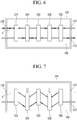
- FIG. 6 and FIG. 7 are views provided for description of operation of the manufacturing apparatus used for manufacturing the long fiber composite material.
- a manufacturing apparatus of the long fiber composite material including a main body 100, a first through-hole plate 300, and a second through-hole plate 500, is prepared.
- the long fiber composite material can be manufactured by using the long fiber composite material manufacturing apparatus that includes the main body 100, the first through-hole plate 300, and the second through-hole plate 500.
- the first through-hole plate 300 and the second through-hole plate 500 through which a plurality of bundles of fiber P penetrate are disposed at different heights, and thus a resin 700 can be uniformly impregnated to the plurality of bundles of fiber P that spread in a width direction (i.e., x-axis direction in the drawing).
- the manufacturing apparatus used in the present exemplary embodiment may include the main body 100, the first through-hole plate 300, and the second through-hole plate 500.
- the main body 100 is a die for impregnation or an impregnation tank where a space is formed therein, and the first through-hole plate 300 and the second through-hole plate 500 may be disposed in the space.
- a resin having high or low viscosity and impregnated to the bundle of fiber may be stored in the space.
- an inlet 130 through which the plurality of bundles of fiber P are inserted to the space in the main body 100 may be provided in one side of the main body 100.
- the inlet 130 is provided in plural, and each of the bundles of fiber P may be injected through an inlet 130.
- the inlet 130 may be provided as a single opening through which the plurality of bundles of fiber P may be injected all together through the inlet 130.
- an outlet 110 through which the plurality of bundles of fiber P are discharged may be provided in the other side of the main body 100. That is, the plurality of bundles of fiber P are injected to the main body 100 through the inlet 130 of the main body 100, impregnated with the resin 700, and then discharged through the outlet 110.
- the outlet 110 may be formed corresponding to the plurality of inlets 130. That is, the number of outlets 110 and the number of inlets 130 may be the same.
- each of the plurality of bundles of fiber P may be injected through an inlet 130 and then discharged through an outlet 110 that corresponds to the inlet 130.
- a plurality of first through-hole plates 300 may be disposed in the space of the main body 100.
- the plurality of bundles of fiber P injected into the space through the inlet 130 may penetrate through the plurality of first through-hole plates 300.
- the plurality of first through-hole plates 300 may be disposed in parallel with each other along a first direction (i.e., Z-axis direction in the drawing). That is, the plurality of first through-hole plates 300 are disposed in parallel with the first direction, which is a progress direction of the plurality of bundles of fiber P.
- the plurality of first through-hole plates 300 include three first through-hole plates 310, 330, and 350. However, this is not restrictive, and the plurality of first through-hole plates 300 may include two or more first through-hole plates.
- the plurality of first through-holes 310, 330, and 350 may be apart from each other by a predetermined gap along the first direction.
- the gap between each of the plurality of first through-hole plates 310, 330, and 350 can be adjusted.
- the gap can be adjusted according to a type of the bundle of fiber P or a type of the resin 700 to be impregnated.
- a plurality of through-holes 313 may be provided in each of the plurality of first through-hole plates 310, 330, and 350.
- the plurality of through-holes 313 are provided in a first body 311 of each of the first through-hole plates 310, 330, and 350.
- the plurality of through-holes 313 may be disposed apart from each other with a constant gap along a third direction (i.e., X-axis direction) that is perpendicular to the first direction.
- the plurality of through-holes 313 may be arranged in two lines along the third direction. However, this is not restrictive, and the plurality of through-holes 313 may be arranged in one line or three or more lines.
- Each of the plurality of bundles of fiber P may penetrate each of the plurality of through-holes 313.
- one fiber bundle P may penetrate one through-hole 313.
- one fiber bundle P among the plurality of fiber bundles P may be formed of thousands or tens of thousands of strands of filaments.
- inner sides of the plurality of through-holes 313 of the first body 313 may be curved. As shown in FIG. 3 , since the inner sides of the through-holes 313, which contact the plurality of fiber bundles P, are curved, the plurality of fiber bundles P can be easily penetrated through the through-holes 313.
- the second through-hole plate 500 may be provided in plural.
- second through-hole plates 510 and 530 may be disposed between the plurality of first through-hole plates 310, 330, and 350. More specifically, one second through-hole plate may be disposed between a pair of first through-hole plates that are adjacent to each other among the plurality of first through-hole plates 310, 330, and 350.
- the second through-hole plate 510 may be disposed between the first through-hole plates 310 and 330
- the second through-hole plate 530 may be disposed between the first through-hole plates 330 and 350.
- the plurality of fiber bundles P that penetrate the first through-hole plate 310 penetrate the second through-hole plate 510.
- the plurality of fiber bundles P penetrated through the second through-hole plate 510 may penetrate the first through-hole plate 330.
- the plurality of fiber bundles P penetrated through the first through-hole plate 330 may penetrate the second through-hole plate 530. Then, the plurality of fiber bundles P penetrated through the second through-hole plate 530 may penetrate the first through-hole plate 350.
- long holes 515 may be provided in the plurality of second through-hole plates 510 and 530.
- the long hole 515 may be provided in a second body 511 of the second through-hole plate 510 and is opened along the third direction. Similar to the first through-hole plates 310, 330, and 350, the long holes 515 may be arranged in two lines along the third direction. However, this is not restrictive, and the long holes 515 may be arranged in one or three or more lines.
- a plurality of protrusions 513 may be provided in each long hole 515.
- the plurality of protrusions 513 may be provided in an inner wall of the long hole 515.
- the plurality of protrusion 513 may be convex toward the ground.
- the number of protrusions 513 may correspond to the number of through-holes 313 provided in the plurality of first through-hole plates 310, 330, and 350.
- the number of protrusions 513 formed in the long hole 515 may be the same as the number of through-holes 313 shown in FIG. 2 .
- the number of protrusions 513 may be greater than the number of through-holes 313.
- Each of the plurality of protrusions 513 may have a curved shape.
- the plurality of protrusions 513 may have a shape of a semi-circle or a half oval, or may have a partially curved shape.
- the plurality of protrusions 513 of the second main body 511 are curved along the first direction. As shown in FIG. 5 , a plurality of protrusions 513 that contact the plurality of fiber bundles P have curved external surfaces so that the plurality of fiber bundles P can easily penetrate the protrusions 513.
- the second through-hole plates 510 and 530 that are disposed between the plurality of first through-hole plates 310, 330, and 350 may move in a second direction (i.e., Y-axis direction in the drawing) that is perpendicular to the first direction and the third direction.
- the second through-hole plates 510 and 530 may vertically move along the second direction.
- tension applied to the plurality of fiber bundles P that penetrate the second through-hole plates 510 and 530 can be adjusted by vertically moving the second through-hole plates 510 and 530 along the second direction.
- the first through-hole plate 300 and the second through-hole plate 500 are placed at the same height.
- the term "the same height” implies that the plurality of through-holes 313 of the first through-hole plate 300 and the long holes 515 of the second through-hole plate 500 have the same height. More specifically, the first through-hole plate 300 and the second through-hole plate 500 are controlled to ensure that the plurality of through-holes 313 of the first through-hole plate 300 and the long holes 515 of the second through-hole plate 500 are straight.
- the plurality of fiber bundles P penetrate the first through-hole plate 300 and the second through-hole plate 500 that are disposed at the same height. More specifically, the plurality of fiber bundles P sequentially penetrate the plurality of through-holes 313 of the first through-hole plate 300 and the long holes 515 of the second through-hole plate 500.
- the plurality of fiber bundles P are sequentially penetrated in order of the first through-hole plate 310, the second through-hole plate 510, the first through-hole plate 330, the second through-hole plate 530, and the first through-hole plate 350.
- the plurality of fiber bundles P form a straight line. That is, the plurality of fiber bundles P do not bent while penetrating the first through-hole plate 300 and the second through-hole plate 500.
- the second through-hole plates 510 and 530 are moved down along the second direction.
- the second through-hole plates 510 and 530 are moved down, but this is not restrictive.
- the second through-hole plates 510 and 530 may be moved upward.
- tension may be applied to the plurality of fiber bundles P that penetrate the second through-hole plates 510 and 530.
- tension When the tension is applied to the plurality of fiber bundles P, a cross-sectional shape of the fiber bundle P that penetrate the long holes 515 of the second through-hole plates 510 and 530 may be deformed.
- FIG. 8 shows a cross-sectional shape of the fiber bundle in the first through-hole plates 310, 330, and 350 and the second through-hole plates 510 and 530 of FIG. 7 .
- a shape of a cross-section of fiber bundle P1 that penetrates the first through-hole plate 310 is close to circular.
- a shape of a cross-section of fiber bundle P2 that penetrates the second through-hole plate 510 is deformed to be unlike the cross-section of FIG. 8 (A) .
- the fiber bundle P2 penetrating the second through-hole plate 510 is applied with tension, and thus the fiber bundles P are deformed by the protrusions 513 that are in contact with the fiber bundles P2.
- the fiber bundles P2 may be flattened and spread.
- one fiber bundle P1 may be formed of thousands or tens of thousands of strands of fiber filaments.
- gaps between thousands of strands of fiber filaments that form the fiber bundle P may be increased.
- pores occur between the fiber filaments such that the resin 700 may be permeated between the pores. Accordingly, the resin 700 can be easily coated to surfaces of the fiber filaments that form the fiber bundle P2.
- the shapes of the plurality of fiber bundles P penetrated through the first through-hole plate 330 recover shapes that are close to circles. Then, the pores between the fiber filaments that form the plurality of fiber bundles P are reduced.
- the pores between the fiber filaments of the plurality of fiber bundles P are iteratively increased and decreased.
- the resin 700 can be uniformly impregnated to the fiber bundles P.
- the plurality of fiber bundles P are continuously injected to the main body 100 so as to continuously manufacture a long fiber composite material. That is, the plurality of fiber bundles P are moved in a direction of the outlet 110 from the inject hole 130 of the main body 100. The plurality of fiber bundles P are impregnated to the resin 700 and then discharged while passing through the main body 100.
- the resin 700 is uniformly impregnated to fiber bundles P of the long fiber composite material manufactured by using the manufacturing method of the long fiber composite material according to the present exemplary embodiment.
- FIG. 9 is a photograph of an enlarged surface of long fiber composite materials manufactured by the present exemplary embodiment and a comparative example
- FIG. 10 is a photograph of long fiber composite material cuts manufactured by the present exemplary embodiment and the comparative example.
- the resin 700 coated to the fiber bundles P according to the manufacturing method of the present exemplary embodiment (B) includes a polypropylene resin, a black pigment, an antioxidant, and the like.
- the fiber bundle P glass fiber is used.
- An internal temperature of the main body 100 is 200 °C to 300 °C, and a moving speed of the plurality of fiber bundles P that penetrate the main body 100 is 300 m/min.
- the above-stated material or temperature is the same, but plates through which the fiber bundles P are penetrated maintain the same height.
- FIG. 10 compared to the comparative example of FIG. 10 (A) , the resin 700 is uniformly coated to the long fiber composite material of the present exemplary embodiment of FIG. 10 (B).
- FIG. 10 shows long fiber composite material cuts, and an area where the resin 700 is not coated in the long fiber composite material (i.e., an area where white fiber bundle exists in the left side of FIG. 10 (A) ) is shown in FIG. 10 (A) .
- the plurality of fiber bundles P that penetrate the main body 100 iteratively penetrate the first through-hole plates 310, 330, and 350 and the second through-hole plates 510 and 530, and thus the pores between the fiber filaments of the plurality of fiber bundles P are iteratively increased and decreased. Accordingly, the fiber bundles P can be uniformly impregnated by the resin 700.
Landscapes
- Engineering & Computer Science (AREA)
- Mechanical Engineering (AREA)
- Chemical & Material Sciences (AREA)
- Textile Engineering (AREA)
- Composite Materials (AREA)
- Life Sciences & Earth Sciences (AREA)
- Wood Science & Technology (AREA)
- Chemical Kinetics & Catalysis (AREA)
- Moulding By Coating Moulds (AREA)
- Reinforced Plastic Materials (AREA)
Applications Claiming Priority (1)
| Application Number | Priority Date | Filing Date | Title |
|---|---|---|---|
| KR1020160083485A KR101740657B1 (ko) | 2016-07-01 | 2016-07-01 | 장섬유 복합재의 제조 방법 |
Publications (2)
| Publication Number | Publication Date |
|---|---|
| EP3263304A1 true EP3263304A1 (de) | 2018-01-03 |
| EP3263304B1 EP3263304B1 (de) | 2018-12-26 |
Family
ID=58191293
Family Applications (1)
| Application Number | Title | Priority Date | Filing Date |
|---|---|---|---|
| EP17157724.0A Active EP3263304B1 (de) | 2016-07-01 | 2017-02-23 | Verfahren zur herstellung von langfaser verstärktem verbundwerkstoff |
Country Status (7)
| Country | Link |
|---|---|
| US (1) | US10695796B2 (de) |
| EP (1) | EP3263304B1 (de) |
| JP (1) | JP6480496B2 (de) |
| KR (1) | KR101740657B1 (de) |
| CN (1) | CN107553773B (de) |
| ES (1) | ES2713507T3 (de) |
| HU (1) | HUE042229T2 (de) |
Cited By (1)
| Publication number | Priority date | Publication date | Assignee | Title |
|---|---|---|---|---|
| EP4011604A1 (de) * | 2020-12-14 | 2022-06-15 | Covestro Deutschland AG | Eintauchvorrichtung und pultrusionsausrüstung damit |
Families Citing this family (1)
| Publication number | Priority date | Publication date | Assignee | Title |
|---|---|---|---|---|
| CN111844522A (zh) * | 2020-08-17 | 2020-10-30 | 湖南强泰环保科技有限公司 | 一种用于玻璃纤维浸树脂的装置 |
Citations (4)
| Publication number | Priority date | Publication date | Assignee | Title |
|---|---|---|---|---|
| US5540797A (en) * | 1995-03-24 | 1996-07-30 | Wilson; Maywood L. | Pultrusion apparatus and process |
| WO2001081073A1 (fr) * | 2000-04-25 | 2001-11-01 | Saint-Gobain Vetrotex France S.A. | Procede et dispositif de fabrication d'un profile composite forme de matiere organique thermoplastique renforcee par des fibres de renforcement |
| JP2007175959A (ja) * | 2005-12-27 | 2007-07-12 | Owens Corning Seizo Kk | 長繊維強化熱可塑性樹脂材料の製造装置及びその製造方法 |
| DE102012013448A1 (de) * | 2012-07-05 | 2014-05-08 | Daimler Ag | Faserbündel-Führungseinrichtung zur Anordnung in einer Pultrusionsvorrichtung und Pultrusionsvorrichtung mit einer solchen Faserbündel-Führungseinrichtung |
Family Cites Families (20)
| Publication number | Priority date | Publication date | Assignee | Title |
|---|---|---|---|---|
| US4439387A (en) | 1979-09-13 | 1984-03-27 | Polymer Composites, Inc. | Method of manufacturing a composite reinforcing structure |
| US4549920A (en) | 1981-07-28 | 1985-10-29 | Imperial Chemical Industries, Plc | Method for impregnating filaments with thermoplastic |
| US4728387A (en) | 1986-12-15 | 1988-03-01 | General Electric Company | Resin impregnation of fiber structures |
| US4946538A (en) * | 1988-12-28 | 1990-08-07 | Andrew M. Zsolnay | Precision apparatus for placing filaments |
| FR2651719B1 (fr) | 1989-09-14 | 1992-02-07 | Saint Gobain Vetrotex | Dispositif d'enrobage des fibres d'un faisceau par de la resine. |
| KR100203471B1 (ko) | 1996-09-20 | 1999-06-15 | 성기웅 | 섬유의 연속코팅 방법 및 장치 |
| KR100221361B1 (ko) | 1997-07-14 | 1999-09-15 | 이정국 | 섬유의 연속코팅 방법 및 장치 |
| JP2000254978A (ja) | 1999-03-08 | 2000-09-19 | Kobe Steel Ltd | Frp細線条体の製造方法 |
| JP2000272021A (ja) | 1999-03-29 | 2000-10-03 | Kobe Steel Ltd | Frp細線条体の製造用金型およびfrp細線条体の製造方法 |
| JP3670906B2 (ja) | 1999-10-18 | 2005-07-13 | 積水化学工業株式会社 | 繊維強化樹脂成形品の製造方法及び製造装置 |
| JP2001162689A (ja) | 1999-12-08 | 2001-06-19 | Toray Ind Inc | 繊維束搬送方法および搬送装置ならびにプリプレグの製造方法 |
| KR100343518B1 (ko) | 2000-02-09 | 2002-07-18 | 정호갑 | 장섬유 복합재 및 그 제조방법과 제조장치 |
| JP3667294B2 (ja) | 2002-04-16 | 2005-07-06 | 旭ファイバーグラス株式会社 | 長繊維強化熱可塑性樹脂材料の製造装置および製造方法 |
| JP4646108B2 (ja) | 2004-06-30 | 2011-03-09 | オーウェンスコーニング製造株式会社 | 長繊維強化樹脂成形材料の製造方法およびその製造装置 |
| JP4633514B2 (ja) | 2005-03-30 | 2011-02-16 | オーウェンスコーニング製造株式会社 | 長繊維強化熱可塑性樹脂ロッドの冷却装置 |
| JP2006289714A (ja) | 2005-04-08 | 2006-10-26 | Prime Polymer:Kk | 繊維強化樹脂成形材料の製造方法及び製造装置 |
| KR100912734B1 (ko) | 2007-12-26 | 2009-08-19 | 주식회사 크리켐 | 장섬유 복합재 제조장치 |
| KR101279328B1 (ko) | 2011-01-05 | 2013-06-26 | 지에스칼텍스 주식회사 | 장섬유 강화 열가소성 수지 펠릿의 제조장치 |
| US20140037842A1 (en) | 2011-04-12 | 2014-02-06 | Ticona Llc | Impregnation Section of Die and Method for Impregnating Fiber Rovings |
| WO2016147864A1 (ja) | 2015-03-19 | 2016-09-22 | 東レ株式会社 | 樹脂含浸繊維束の製造方法および樹脂含浸繊維束の巻取体の製造方法 |
-
2016
- 2016-07-01 KR KR1020160083485A patent/KR101740657B1/ko active Active
-
2017
- 2017-01-03 US US15/396,876 patent/US10695796B2/en active Active
- 2017-02-04 CN CN201710064442.6A patent/CN107553773B/zh active Active
- 2017-02-23 EP EP17157724.0A patent/EP3263304B1/de active Active
- 2017-02-23 HU HUE17157724A patent/HUE042229T2/hu unknown
- 2017-02-23 ES ES17157724T patent/ES2713507T3/es active Active
- 2017-03-16 JP JP2017051622A patent/JP6480496B2/ja active Active
Patent Citations (4)
| Publication number | Priority date | Publication date | Assignee | Title |
|---|---|---|---|---|
| US5540797A (en) * | 1995-03-24 | 1996-07-30 | Wilson; Maywood L. | Pultrusion apparatus and process |
| WO2001081073A1 (fr) * | 2000-04-25 | 2001-11-01 | Saint-Gobain Vetrotex France S.A. | Procede et dispositif de fabrication d'un profile composite forme de matiere organique thermoplastique renforcee par des fibres de renforcement |
| JP2007175959A (ja) * | 2005-12-27 | 2007-07-12 | Owens Corning Seizo Kk | 長繊維強化熱可塑性樹脂材料の製造装置及びその製造方法 |
| DE102012013448A1 (de) * | 2012-07-05 | 2014-05-08 | Daimler Ag | Faserbündel-Führungseinrichtung zur Anordnung in einer Pultrusionsvorrichtung und Pultrusionsvorrichtung mit einer solchen Faserbündel-Führungseinrichtung |
Cited By (1)
| Publication number | Priority date | Publication date | Assignee | Title |
|---|---|---|---|---|
| EP4011604A1 (de) * | 2020-12-14 | 2022-06-15 | Covestro Deutschland AG | Eintauchvorrichtung und pultrusionsausrüstung damit |
Also Published As
| Publication number | Publication date |
|---|---|
| CN107553773A (zh) | 2018-01-09 |
| JP6480496B2 (ja) | 2019-03-13 |
| HUE042229T2 (hu) | 2019-06-28 |
| KR101740657B1 (ko) | 2017-05-26 |
| US20180001345A1 (en) | 2018-01-04 |
| JP2018001743A (ja) | 2018-01-11 |
| US10695796B2 (en) | 2020-06-30 |
| CN107553773B (zh) | 2019-12-24 |
| ES2713507T3 (es) | 2019-05-22 |
| EP3263304B1 (de) | 2018-12-26 |
Similar Documents
| Publication | Publication Date | Title |
|---|---|---|
| EP3266577A1 (de) | Vorrichtung zur herstellung von langfaserverstärktem verbundwerkstoff | |
| US20190062956A1 (en) | Fiber tow treatment system and method | |
| DE102011011112A1 (de) | Verfahren zur Herstellung einer Litze oder eines Seils | |
| EP3263304B1 (de) | Verfahren zur herstellung von langfaser verstärktem verbundwerkstoff | |
| HUE025211T2 (en) | Equipment for the production of microfibre and nanofibre two-dimensional or three-dimensional fiber materials | |
| DE102017103128A1 (de) | Spulensegment für eine Statorspule und Verfahren zur Herstellung eines Spulensegments | |
| EP3340347A1 (de) | Vorrichtung und verfahren zur herstellung von elektroden | |
| DE102015208935B4 (de) | Öffnungsvorrichtung eines Faserbündels | |
| EP1972033A2 (de) | Kontaktzelle zur aufnahme eines kabelendes mittels schneidklemmtechnik und verfahren zu deren herstellung | |
| WO2014095819A2 (de) | 2-komponenten isolation von bl-statoren | |
| KR101962764B1 (ko) | 장섬유 복합재의 제조 장치 | |
| DE102014001982B3 (de) | Vorrichtung und Verfahren zum Erreichen eines verbesserten Infusionsverhaltens von Trockenfasergelegen sowie damit erhältliche Bauteile | |
| WO2015010781A1 (de) | Kabelentwirrer, elektrodenkabelstrang mit kabelentwirrer und elektrokardiogrammgerät | |
| WO2023057135A1 (de) | Batterieschale aufweisend ein relief und eine abschirmungsschicht, werkzeug, verfahren und traktionsbatterie | |
| EP3561905B1 (de) | Verfahren zur herstellung eines batterieelementes für eine batteriezelle sowie verwendung | |
| DE102014213187A1 (de) | Presswerkzeug mit optimiertem Harzfluss | |
| DE102011079731A1 (de) | Schrumpfschlauch | |
| EP3261825B1 (de) | Pultrusionsverfahren zur herstellung von faserverstärkten kunststoffprofilen | |
| EP3474391A1 (de) | Verfahren zum verbinden mindestens zweier mehrdrähtiger litzen mittels ultraschalls | |
| EP4219137A1 (de) | Verfahren und vorrichtung zur herstellung eines ringförmigen multiaxialen fadengeleges sowie ein damit hergestellter ringförmiger gegenstand | |
| DE102014211016B3 (de) | Verfahren zur Herstellung eines Faser-Halbzeugs, Faser-Halbzeug zur Herstellung eines Faserverbundwerkstoffs sowie Bauteil aus einem Faserverbundwerkstoff und lokal definierter Permeabilität | |
| WO2022218580A1 (de) | Werkzeug zur herstellung von schaumstoffteilen | |
| DE102016121487A1 (de) | Vorrichtung und Verfahren zum Herstellen eines Tubularelements | |
| DE6922421U (de) | Vorrichtung zur herstellung eines nichtgewebten textilvlieses | |
| EP3513939A1 (de) | Vorrichtung und verfahren zur fertigung eines fasern- und matrixkunststoff enthaltenden verbundwerkstoffes |
Legal Events
| Date | Code | Title | Description |
|---|---|---|---|
| PUAI | Public reference made under article 153(3) epc to a published international application that has entered the european phase |
Free format text: ORIGINAL CODE: 0009012 |
|
| STAA | Information on the status of an ep patent application or granted ep patent |
Free format text: STATUS: REQUEST FOR EXAMINATION WAS MADE |
|
| 17P | Request for examination filed |
Effective date: 20170313 |
|
| AK | Designated contracting states |
Kind code of ref document: A1 Designated state(s): AL AT BE BG CH CY CZ DE DK EE ES FI FR GB GR HR HU IE IS IT LI LT LU LV MC MK MT NL NO PL PT RO RS SE SI SK SM TR |
|
| AX | Request for extension of the european patent |
Extension state: BA ME |
|
| RAP1 | Party data changed (applicant data changed or rights of an application transferred) |
Owner name: LOTTE CHEMICAL CORPORATION |
|
| RBV | Designated contracting states (corrected) |
Designated state(s): AL AT BE BG CH CY CZ DE DK EE ES FI FR GB GR HR HU IE IS IT LI LT LU LV MC MK MT NL NO PL PT RO RS SE SI SK SM TR |
|
| GRAP | Despatch of communication of intention to grant a patent |
Free format text: ORIGINAL CODE: EPIDOSNIGR1 |
|
| STAA | Information on the status of an ep patent application or granted ep patent |
Free format text: STATUS: GRANT OF PATENT IS INTENDED |
|
| INTG | Intention to grant announced |
Effective date: 20180725 |
|
| GRAS | Grant fee paid |
Free format text: ORIGINAL CODE: EPIDOSNIGR3 |
|
| GRAA | (expected) grant |
Free format text: ORIGINAL CODE: 0009210 |
|
| STAA | Information on the status of an ep patent application or granted ep patent |
Free format text: STATUS: THE PATENT HAS BEEN GRANTED |
|
| AK | Designated contracting states |
Kind code of ref document: B1 Designated state(s): AL AT BE BG CH CY CZ DE DK EE ES FI FR GB GR HR HU IE IS IT LI LT LU LV MC MK MT NL NO PL PT RO RS SE SI SK SM TR |
|
| REG | Reference to a national code |
Ref country code: GB Ref legal event code: FG4D |
|
| REG | Reference to a national code |
Ref country code: CH Ref legal event code: EP |
|
| REG | Reference to a national code |
Ref country code: AT Ref legal event code: REF Ref document number: 1080773 Country of ref document: AT Kind code of ref document: T Effective date: 20190115 |
|
| REG | Reference to a national code |
Ref country code: DE Ref legal event code: R096 Ref document number: 602017001501 Country of ref document: DE |
|
| REG | Reference to a national code |
Ref country code: IE Ref legal event code: FG4D |
|
| PG25 | Lapsed in a contracting state [announced via postgrant information from national office to epo] |
Ref country code: FI Free format text: LAPSE BECAUSE OF FAILURE TO SUBMIT A TRANSLATION OF THE DESCRIPTION OR TO PAY THE FEE WITHIN THE PRESCRIBED TIME-LIMIT Effective date: 20181226 Ref country code: LV Free format text: LAPSE BECAUSE OF FAILURE TO SUBMIT A TRANSLATION OF THE DESCRIPTION OR TO PAY THE FEE WITHIN THE PRESCRIBED TIME-LIMIT Effective date: 20181226 Ref country code: NO Free format text: LAPSE BECAUSE OF FAILURE TO SUBMIT A TRANSLATION OF THE DESCRIPTION OR TO PAY THE FEE WITHIN THE PRESCRIBED TIME-LIMIT Effective date: 20190326 Ref country code: LT Free format text: LAPSE BECAUSE OF FAILURE TO SUBMIT A TRANSLATION OF THE DESCRIPTION OR TO PAY THE FEE WITHIN THE PRESCRIBED TIME-LIMIT Effective date: 20181226 Ref country code: HR Free format text: LAPSE BECAUSE OF FAILURE TO SUBMIT A TRANSLATION OF THE DESCRIPTION OR TO PAY THE FEE WITHIN THE PRESCRIBED TIME-LIMIT Effective date: 20181226 Ref country code: BG Free format text: LAPSE BECAUSE OF FAILURE TO SUBMIT A TRANSLATION OF THE DESCRIPTION OR TO PAY THE FEE WITHIN THE PRESCRIBED TIME-LIMIT Effective date: 20190326 |
|
| REG | Reference to a national code |
Ref country code: NL Ref legal event code: MP Effective date: 20181226 |
|
| REG | Reference to a national code |
Ref country code: LT Ref legal event code: MG4D |
|
| REG | Reference to a national code |
Ref country code: ES Ref legal event code: FG2A Ref document number: 2713507 Country of ref document: ES Kind code of ref document: T3 Effective date: 20190522 |
|
| PG25 | Lapsed in a contracting state [announced via postgrant information from national office to epo] |
Ref country code: AL Free format text: LAPSE BECAUSE OF FAILURE TO SUBMIT A TRANSLATION OF THE DESCRIPTION OR TO PAY THE FEE WITHIN THE PRESCRIBED TIME-LIMIT Effective date: 20181226 Ref country code: GR Free format text: LAPSE BECAUSE OF FAILURE TO SUBMIT A TRANSLATION OF THE DESCRIPTION OR TO PAY THE FEE WITHIN THE PRESCRIBED TIME-LIMIT Effective date: 20190327 Ref country code: SE Free format text: LAPSE BECAUSE OF FAILURE TO SUBMIT A TRANSLATION OF THE DESCRIPTION OR TO PAY THE FEE WITHIN THE PRESCRIBED TIME-LIMIT Effective date: 20181226 Ref country code: RS Free format text: LAPSE BECAUSE OF FAILURE TO SUBMIT A TRANSLATION OF THE DESCRIPTION OR TO PAY THE FEE WITHIN THE PRESCRIBED TIME-LIMIT Effective date: 20181226 |
|
| REG | Reference to a national code |
Ref country code: AT Ref legal event code: MK05 Ref document number: 1080773 Country of ref document: AT Kind code of ref document: T Effective date: 20181226 |
|
| PG25 | Lapsed in a contracting state [announced via postgrant information from national office to epo] |
Ref country code: NL Free format text: LAPSE BECAUSE OF FAILURE TO SUBMIT A TRANSLATION OF THE DESCRIPTION OR TO PAY THE FEE WITHIN THE PRESCRIBED TIME-LIMIT Effective date: 20181226 |
|
| REG | Reference to a national code |
Ref country code: HU Ref legal event code: AG4A Ref document number: E042229 Country of ref document: HU |
|
| PG25 | Lapsed in a contracting state [announced via postgrant information from national office to epo] |
Ref country code: CZ Free format text: LAPSE BECAUSE OF FAILURE TO SUBMIT A TRANSLATION OF THE DESCRIPTION OR TO PAY THE FEE WITHIN THE PRESCRIBED TIME-LIMIT Effective date: 20181226 Ref country code: PT Free format text: LAPSE BECAUSE OF FAILURE TO SUBMIT A TRANSLATION OF THE DESCRIPTION OR TO PAY THE FEE WITHIN THE PRESCRIBED TIME-LIMIT Effective date: 20190426 Ref country code: PL Free format text: LAPSE BECAUSE OF FAILURE TO SUBMIT A TRANSLATION OF THE DESCRIPTION OR TO PAY THE FEE WITHIN THE PRESCRIBED TIME-LIMIT Effective date: 20181226 Ref country code: IT Free format text: LAPSE BECAUSE OF FAILURE TO SUBMIT A TRANSLATION OF THE DESCRIPTION OR TO PAY THE FEE WITHIN THE PRESCRIBED TIME-LIMIT Effective date: 20181226 |
|
| PG25 | Lapsed in a contracting state [announced via postgrant information from national office to epo] |
Ref country code: EE Free format text: LAPSE BECAUSE OF FAILURE TO SUBMIT A TRANSLATION OF THE DESCRIPTION OR TO PAY THE FEE WITHIN THE PRESCRIBED TIME-LIMIT Effective date: 20181226 Ref country code: IS Free format text: LAPSE BECAUSE OF FAILURE TO SUBMIT A TRANSLATION OF THE DESCRIPTION OR TO PAY THE FEE WITHIN THE PRESCRIBED TIME-LIMIT Effective date: 20190426 Ref country code: SM Free format text: LAPSE BECAUSE OF FAILURE TO SUBMIT A TRANSLATION OF THE DESCRIPTION OR TO PAY THE FEE WITHIN THE PRESCRIBED TIME-LIMIT Effective date: 20181226 Ref country code: RO Free format text: LAPSE BECAUSE OF FAILURE TO SUBMIT A TRANSLATION OF THE DESCRIPTION OR TO PAY THE FEE WITHIN THE PRESCRIBED TIME-LIMIT Effective date: 20181226 Ref country code: SK Free format text: LAPSE BECAUSE OF FAILURE TO SUBMIT A TRANSLATION OF THE DESCRIPTION OR TO PAY THE FEE WITHIN THE PRESCRIBED TIME-LIMIT Effective date: 20181226 |
|
| REG | Reference to a national code |
Ref country code: DE Ref legal event code: R097 Ref document number: 602017001501 Country of ref document: DE |
|
| PG25 | Lapsed in a contracting state [announced via postgrant information from national office to epo] |
Ref country code: LU Free format text: LAPSE BECAUSE OF NON-PAYMENT OF DUE FEES Effective date: 20190223 Ref country code: DK Free format text: LAPSE BECAUSE OF FAILURE TO SUBMIT A TRANSLATION OF THE DESCRIPTION OR TO PAY THE FEE WITHIN THE PRESCRIBED TIME-LIMIT Effective date: 20181226 Ref country code: MC Free format text: LAPSE BECAUSE OF FAILURE TO SUBMIT A TRANSLATION OF THE DESCRIPTION OR TO PAY THE FEE WITHIN THE PRESCRIBED TIME-LIMIT Effective date: 20181226 Ref country code: AT Free format text: LAPSE BECAUSE OF FAILURE TO SUBMIT A TRANSLATION OF THE DESCRIPTION OR TO PAY THE FEE WITHIN THE PRESCRIBED TIME-LIMIT Effective date: 20181226 |
|
| PLBE | No opposition filed within time limit |
Free format text: ORIGINAL CODE: 0009261 |
|
| STAA | Information on the status of an ep patent application or granted ep patent |
Free format text: STATUS: NO OPPOSITION FILED WITHIN TIME LIMIT |
|
| REG | Reference to a national code |
Ref country code: BE Ref legal event code: MM Effective date: 20190228 |
|
| REG | Reference to a national code |
Ref country code: IE Ref legal event code: MM4A |
|
| 26N | No opposition filed |
Effective date: 20190927 |
|
| PG25 | Lapsed in a contracting state [announced via postgrant information from national office to epo] |
Ref country code: IE Free format text: LAPSE BECAUSE OF NON-PAYMENT OF DUE FEES Effective date: 20190223 |
|
| PG25 | Lapsed in a contracting state [announced via postgrant information from national office to epo] |
Ref country code: BE Free format text: LAPSE BECAUSE OF NON-PAYMENT OF DUE FEES Effective date: 20190228 Ref country code: SI Free format text: LAPSE BECAUSE OF FAILURE TO SUBMIT A TRANSLATION OF THE DESCRIPTION OR TO PAY THE FEE WITHIN THE PRESCRIBED TIME-LIMIT Effective date: 20181226 |
|
| PG25 | Lapsed in a contracting state [announced via postgrant information from national office to epo] |
Ref country code: TR Free format text: LAPSE BECAUSE OF FAILURE TO SUBMIT A TRANSLATION OF THE DESCRIPTION OR TO PAY THE FEE WITHIN THE PRESCRIBED TIME-LIMIT Effective date: 20181226 |
|
| PG25 | Lapsed in a contracting state [announced via postgrant information from national office to epo] |
Ref country code: MT Free format text: LAPSE BECAUSE OF NON-PAYMENT OF DUE FEES Effective date: 20190223 |
|
| REG | Reference to a national code |
Ref country code: CH Ref legal event code: PL |
|
| PG25 | Lapsed in a contracting state [announced via postgrant information from national office to epo] |
Ref country code: LI Free format text: LAPSE BECAUSE OF NON-PAYMENT OF DUE FEES Effective date: 20200229 Ref country code: CH Free format text: LAPSE BECAUSE OF NON-PAYMENT OF DUE FEES Effective date: 20200229 |
|
| PG25 | Lapsed in a contracting state [announced via postgrant information from national office to epo] |
Ref country code: CY Free format text: LAPSE BECAUSE OF FAILURE TO SUBMIT A TRANSLATION OF THE DESCRIPTION OR TO PAY THE FEE WITHIN THE PRESCRIBED TIME-LIMIT Effective date: 20181226 |
|
| GBPC | Gb: european patent ceased through non-payment of renewal fee |
Effective date: 20210223 |
|
| PG25 | Lapsed in a contracting state [announced via postgrant information from national office to epo] |
Ref country code: GB Free format text: LAPSE BECAUSE OF NON-PAYMENT OF DUE FEES Effective date: 20210223 |
|
| PG25 | Lapsed in a contracting state [announced via postgrant information from national office to epo] |
Ref country code: MK Free format text: LAPSE BECAUSE OF FAILURE TO SUBMIT A TRANSLATION OF THE DESCRIPTION OR TO PAY THE FEE WITHIN THE PRESCRIBED TIME-LIMIT Effective date: 20181226 |
|
| P01 | Opt-out of the competence of the unified patent court (upc) registered |
Effective date: 20230528 |
|
| PGFP | Annual fee paid to national office [announced via postgrant information from national office to epo] |
Ref country code: HU Payment date: 20260130 Year of fee payment: 10 |
|
| PGFP | Annual fee paid to national office [announced via postgrant information from national office to epo] |
Ref country code: ES Payment date: 20260310 Year of fee payment: 10 |
|
| PGFP | Annual fee paid to national office [announced via postgrant information from national office to epo] |
Ref country code: DE Payment date: 20260107 Year of fee payment: 10 |
|
| PGFP | Annual fee paid to national office [announced via postgrant information from national office to epo] |
Ref country code: FR Payment date: 20260108 Year of fee payment: 10 |